Looking to expand the device capability I stumbled across a really interesting little project that is still in the early stages of development but, is functional and worth trying out.
The TC²-BBS Meshtastic Version is a simple BBS system that runs on a RaspberryPi, Linux PC or virtual machine (VM) and can connect to a Meshtastic device via either serial, USB or TCP/IP. Having my M0AWS-1 Meshtastic node at home connected to Wifi I decided to use a TCP/IP connection to the device from a Linux VM running the Python based TC²-BBS Meshtastic BBS.
Following the instructions on how to deploy the BBS is pretty straight forward and it was up and running in no time at all. With a little editing of the code I soon had the Python based BBS software M0AWS branded and connected to my Meshtastic node-1.
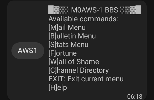
M0AWS Meshtastic BBS Main Menu accessible on M0AWS-1 node.
The BBS system is very reminiscent of the old packet BBS systems of a bygone era but, it is ideal for the Meshtastic world as the simple menus and user interface are easily transmitted in seconds via the Mesh using minimal bandwidth.
The BBS is accessible by opening a Direct Message session with the M0AWS-1 node. Sending the letter H to the node will get you the initial help screen showing the menu above and then from there onwards it’s just a matter of selecting the menu item and following the BBS prompts to use the BBS.
The BBS also works across MQTT. I tested it with Dave, G4PPN and it worked perfectly via the Meshtastic MQTT server.
This simple but, effective BBS for the Meshtastic network will add a new message store/forward capability to the Mesh and could prove to be very important to the development of the Meshtastic mesh in the UK and the rest of the world.
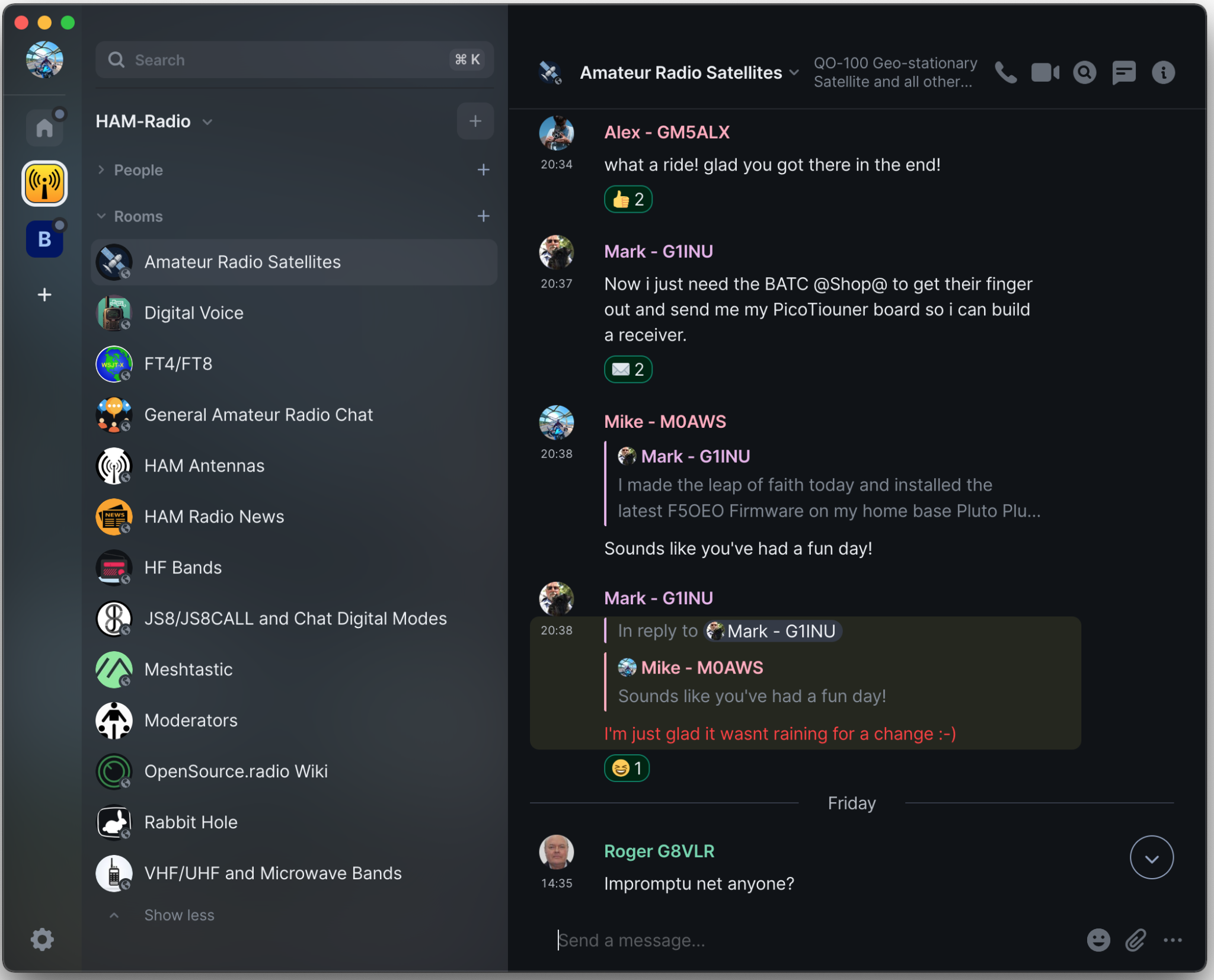
We’ve recently added a new room to the Matrix HAM Radio Space for Digital Voice modes as this was an area of interest that didn’t really fit into any of the other rooms.
The new Digital Voice room has attracted a lot of attention from members, with a lot of the focus being on the AllStarLink system. Michael, DK1MI built an AllStarLink node in the cloud for us all to use for Matrix Nets and so I decided I had to get in on the fun.
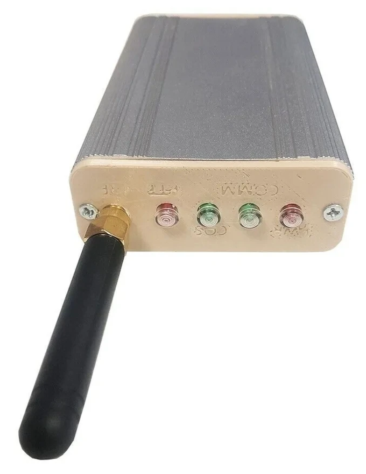
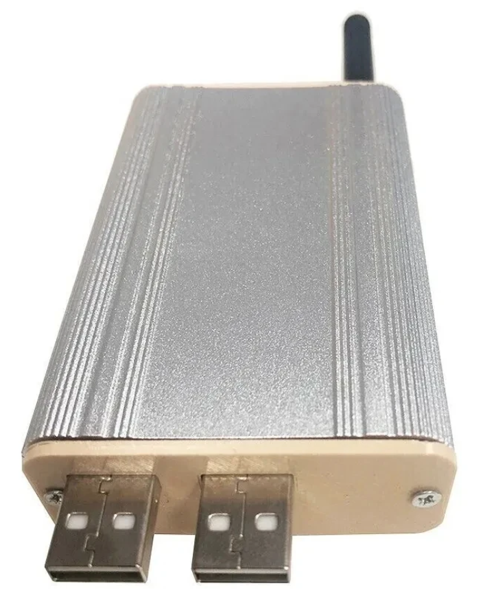
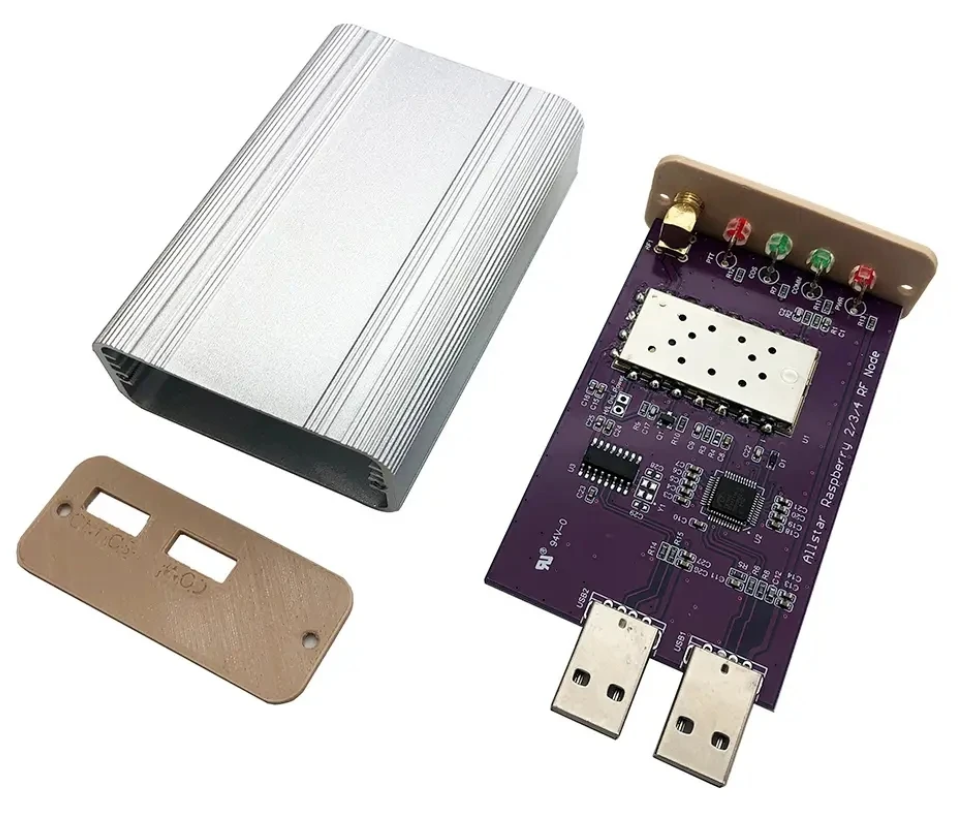
Jumbospot SHARI SA818 Amateur Radio AllStarLink Radio Interface Front Panel ViewJumbospot SHARI SA818 Amateur Radio AllStarLink Radio Interface Rear ViewJumbospot SHARI SA818 Amateur Radio AllStarLink Radio Interface stripped down View
The two USB connectors on the SHARI device are position such that they plug into two of the available 4 USB ports on the RaspberryPi without the need for cables. This keeps the whole solution together in one neat package.
Before you start you will need to obtain a node number and secret (password) from the AllStarLink Portal. To get this you will need to provide proof to the AllStarLink administrators that you are a licensed Amateur Radio (HAM) operator. This is done by uploading a copy of the first page of your HAM licence to the website for the admin team to check. This can take 24hrs to be completed so make sure you get this all done before trying to build your node. You cannot build a node successfully without a node number and secret.
Of course you will also need a transceiver that can operate on the 438.800Mhz frequency or other frequency of your choice on the 2m or 70cm HAM band.
You will also need to open port 4569 on your internet router and setup port forwarding to the IP Address that you will be using on your RaspberryPi node. It’s important to use a static IP Address on your RaspberryPi.
There are quite a few different Linux based operating system (O/S) images that are available for the RaspberryPi devices that have been specifically tailored for the AllStarLink node and include all the necessary software and library packages out the box.
Once downloaded you need to burn the ISO image onto a suitable SD card for your RaspberryPi. I use BalenaEtcher as it’s extremely quick and reliable at burning ISO images to SD cards.
Of course if you are a hardline Linux command line junkie you can always use dd to create the SD card.
Once you’ve got your O/S onto your SD card, slot it into your RaspberryPi making sure your SHARI device is connected to the two USB ports and then power it up. Make sure you have a good PSU for the RaspberryPi as the two devices together draw around 3A of current during the transmit cycle. (I use a 3.6A PSU from Amazon).
The default login for the Raspbian O/S is shown below. Login via SSH and configure your RaspberryPi for your local network. It’s important to use a static IP Address configured either directly on the RaspberryPi or via DHCP in your router.
Next you need to change directory into the asterisk config file directory using the command shown below:
cd /etc/asterisk
In this directory you will find all the default config files that come as part of the distro. For this build we’re not going to use them and so we need to move them out of the way ready for a set of config files that have already been configured correctly.
Using the following commands create a new directory, move into that new directory and then move all the unwanted configuration files into it:
mkdir ORIGINAL-CONF-FILES
cd ./ORIGINAL-CONF-FILES
mv ../*.conf ./
ls -la
cd ../
You should now be back in the /etc/asterisk directory which will now be empty apart from the custom directory which we left in place.
You now need to copy the correctly configured configuration files into the /etc/asterisk directory. Start by downloading the zip file containing the new configuration files
Once downloaded, copy the .zip file into the repeater users home directory (/home/repeater) using either scp on the Linux command line or if using Windows you can use the FileZilla Client in SFTP mode using the login details above.
Once you have the .zip file in the repeater user’s home directory you need to copy the file into the /etc/asterisk directory as user root:
Next as user root, change directory into the /etc/asterisk directory and unzip the .zip file:
cd /etc/asterisk
unzip ./AllStarLink-Config-v3.zip
Once the file is unzipped you will have a directory called AllStarLink-Config in the /etc/asterisk directory. You now need to cd into the directory, copy all the files out of it into the /etc/asterisk directory leaving a copy in the AllStarLink-Config directory for future reference:
cd /etc/asterisk/AllStarLink-Config
cp ./* /etc/asterisk
cd /etc/asterisk
You now need to move a couple of files into the repeater users home directory using the following commands:
The gpioBASH script and configuration details were supplied by Mark, G1INU in the Digital Voice room on the Matrix. It adds the COS light functionality to the setup. The COS light will now light every time the SA818 hears RF on the input.
The next thing you need to do is configure the SA818 radio device in the SHARI. The script I used was originally from https://wiki.fm-funknetz.de/doku.php?id=fm-funknetz:technik:shari-sa818 all I’ve done is change the entries to switch off CTCSS and change the frequency to 438.800Mhz. Configuring the SA818 is done by running the SA818-running.pyPython programme that you moved into the repeater user home directory. Making sure you are still user root, run the following commands:
cd /home/repeater
./SA818-running.py
At this point your SHARI SA818 device will be configured to operate on 438.800Mhz and CTCSS will be disabled.
If you want to change the frequency or enable and set a CTCSS tone to access the node you will need to edit the Python programme using your favourite text editor and change the entries accordingly. Once changed rerun the program as shown above and your SHARI will be reconfigured to your new settings.
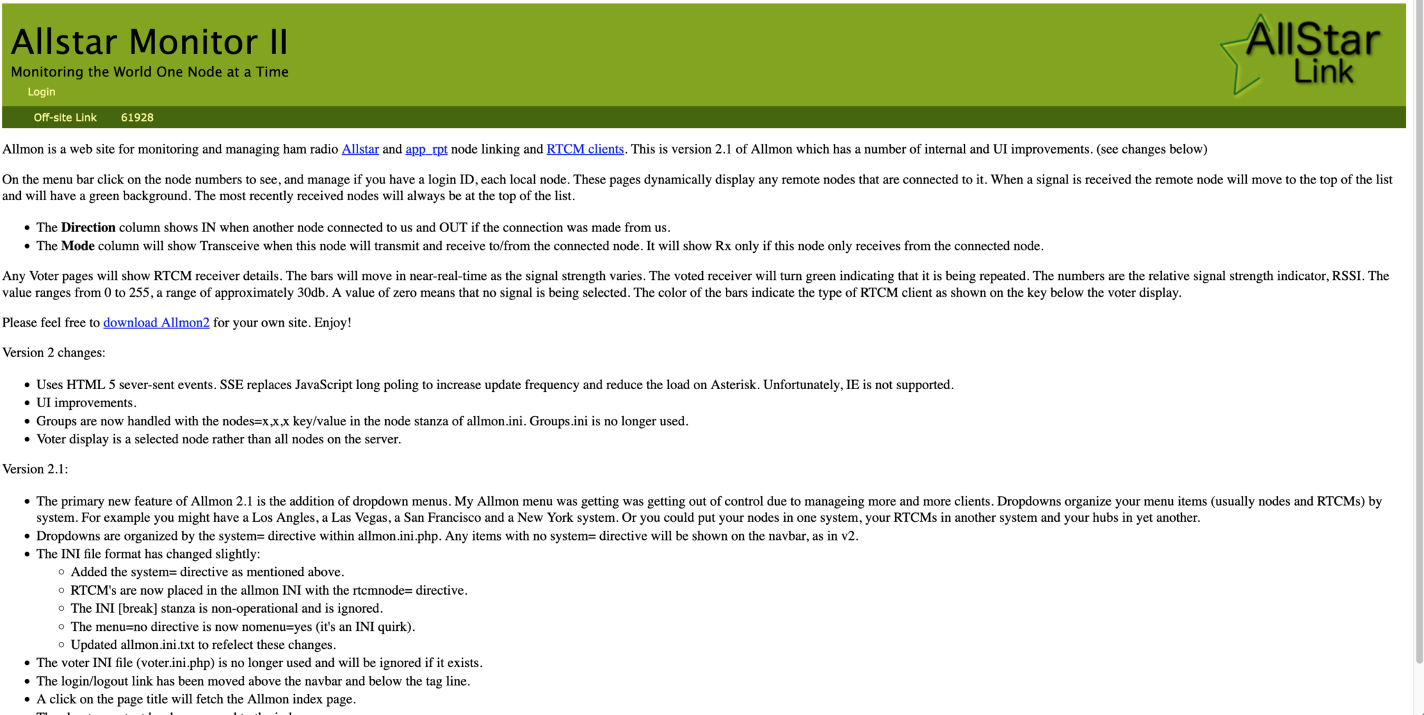
Next you need to move the allmon.ini.php file into the correct directory so that it enables access to the Allstar Monitor web page on the device so that you can manage connecting/disconnecting nodes. Use the following commands as user root to achieve this:
The allmon.ini.php file needs to have your node name entered into it to work correctly. As user root, change directory and edit the file using your favourite editor.
cd /var/www/html/allmon2
Using your text editor, search for the line starting [XXXXX] and change the XXXXX to your node number. Save the change and exit the file.
At this point you are almost complete, all that is left to do is add your node number and node secret into the appropriate configuration files in the /etc/asterisk directory.
Since I am a Linux command line junkie I use vi to edit all the configuration files on the command line as user root, but you can use any editor of your choice.
cd /etc/asterisk
Start with the extensions.conf file. Search for the line starting with NODE = and delete the XXXXX entry and insert your node number. Save the file and exit it.
Next you need to edit the iax.conf file. This time search for the line starting with register= and change the XXXXX for your node number and the YYYYYYYYYYYY for your node secret. Be careful not to accidentally delete any other characters in the lines otherwise it will corrupt the configuration file.
In the same file search for the two lines that start with secret = and change the YYYYYYYYYYYY for your node secret. Once you have changed both of the secret entries, save and exit the file.
The final file to edit is the rpt.conf file. Once again open the file using your favourite editor and search for the line starting with XXXXX = radio@127.0.0.1:4569/XXXXX, change the XXXXX entries for your node number making sure not to delete any other characters next to the XXXXX entries.
Further down in the same file there is a line that starts with [XXXXX], once again change the XXXXX for your node number making sure to keep the square brackets at each end of the node number as you edit it.
Finally move down to the very bottom of the file and find the two lines that start with /home/repeater/gpio, once again change the XXXXX entries for your node number.
The final thing to change in the rpt.conf file is to replace my callsign with your own callsign so that the node identifies itself correctly. Scroll through the file until you find the two lines shown below, delete M0AWS and add your own callsign instead making sure you keep all the spaces between words as shown below.
idrecording = |i DE M0AWS
idtalkover = |i DE M0AWS
Once this is done, save and exit the file. At this point your node should be fully configured and will only require a reboot to get it working.
As user root, reboot your raspi using the reboot command.
reboot
Once your raspi comes back online, login using SSH as user repeater and then become root user using the sudo command detailed above.
You now need to create the admin user password for the Allstar Monitor web page on the device. This is done using the following commands as user root:
cd /var/www/html/allmon2
htpasswd -c .htpasswd admin
You will be asked to enter a password twice for the admin user. Make sure you make a note of this user/password as you will need it to login to the web page.
Finally check that the controlpanel.ini.php file is in the /var/www/html/allmon2 directory:
ls -la /var/www/html/allmon2/controlpanel.ini.php
If the file isn’t shown in the directory, enter the following commands to create the file in the correct place as user root and then exit the SSH session:
cd /var/www/html/allmon2
cp ./controlpanel.ini.txt ./controlpanel.ini.php
cd
exit
Once this is done your configuration is complete, logout from the terminal session by entering exit once more and your SSH session will terminate.
Using your favourite web browser enter the IP Address of your raspi into the URL bar as shown below:
http://<Your-Raspi-IP>/allmon2
Note: remove the <> from the URL once you have entered the required information.
Once this is done you should be presented with your node control panel as shown below.
First visit to the AllStar Monitor Web Page
Login using Admin and the password you set above and you are now ready to start using your node.
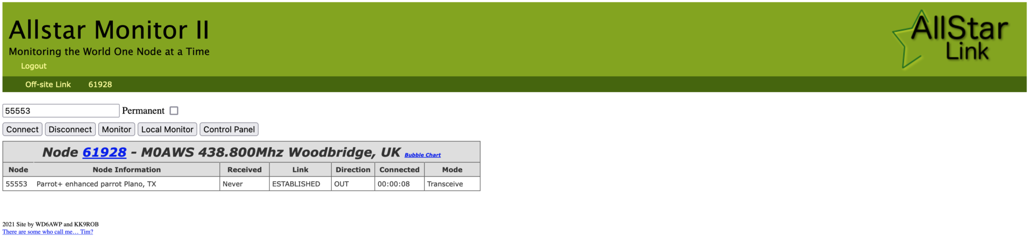
It’s a good idea to connect to node 55553 which is a parrot test node to check your audio levels. You can do this by entering the node into the field at the top left and pressing the connect button.
M0AWS AllStarLink Node 61928 connected to 55553 Parrot
Once connected, tune your radio to 438.800Mhz FM and transmit a test message using your callsign and test123, or something similar. The parrot will then play your recording back to you so that you can hear how you sound. It will also comment on your audio level as to whether it is OK or not.
You are now connected to AllStarLink network and have the world at your finger tips. Below is a small list of nodes in the UK, Australia and America to get you started chatting with other HAMs via your node.
57881	Matrix HAM Radio Space AllStarLink Node (Hosted by Dk1MI)
55553	ASL Parrot for testing
41522	M0HOY HUBNet Manchester, UK
60349	VK6CIA 439.275 Perth, Western Australia
51077	VK6SEG South West Hub B Albany WA
2167	M0JKT FreeSTAR UK HUB 2 freestar.network
53573	NWAG NW AllStar Group Lancashire, UK
27339	East Coast Hub Wilmington NC USA
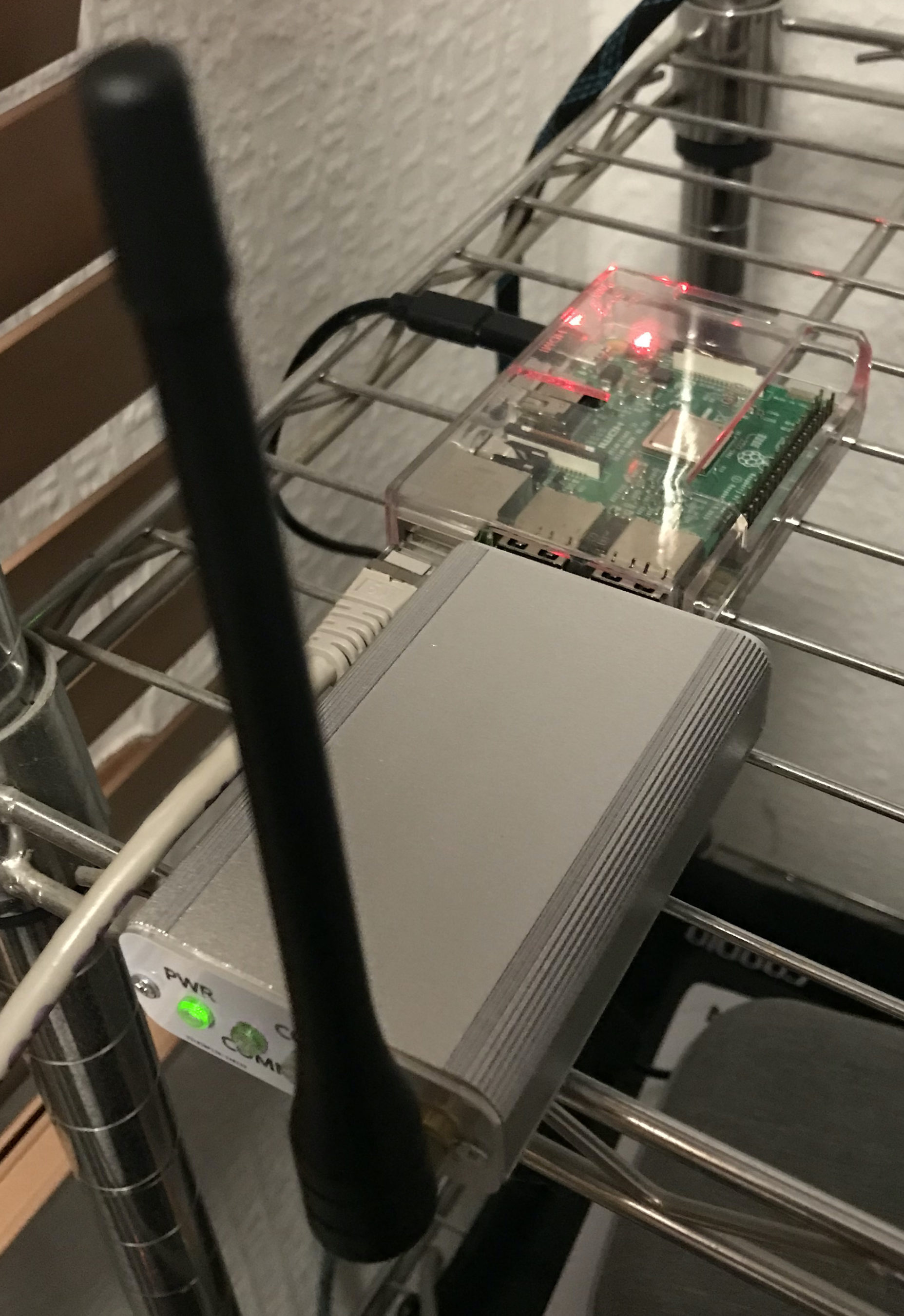
M0AWS AllStarLink Node 61928 sitting on the equipment rack
Thanks to Michael, DK1MI for building and hosting the Matrix HAM Radio Space AllStarLink Node (57881) and getting us all started in the world of AllStarLink!
We hope to be having regular Matrix Net’s on the node soon for all Matrix members and visitors. We’ll organise days/times via the Digital Voice room.
Following on from my article about my QO-100 Satellite Ground Station Complete Build, this article goes into some detail on the Node-RED section of the build and how I put together my QO-100 Satellite Ground Station Dashboard web app.
The Node-RED project has grown organically as I used the QO-100 satellite over time. Initially this started out as a simple project to synchronise the transmit and receive VFO’s so that the SDR receiver always tracked the IC-705 transmitter.
Over time I added more and more functionality until the QO-100 Ground Station Dashboard became the beast it is today.
M0AWS QO-100 Ground Station Control Dashboard built using Node-RED.
Looking at the dashboard web app it looks relatively simple in that it reflects a lot of the functionality that the two radio devices already have in their own rights however, bringing this together is actually more complicated than it first appears.
Starting at the beginning I use FLRig to connect to the IC-705. The connection can be via USB or LAN/Wifi, it makes no difference. Node-RED gains CAT control of the IC-705 via XMLRPC on port 12345 to FLRig.
To control the SDR receiver I use GQRX SDR software and connect to it using RIGCTL on GQRX port 7356 from Node-RED. These two methods of connectivity work well and enables full control of the two radios.
M0AWS Node-RED QO-100 Ground Station Dashboard Flow as of 12/06/24
The complete flow above looks rather daunting initially however, breaking it down into its constituent parts makes it much easier to understand.
There are two sections to the flow, the GQRX control which is the more complex of the two flows and the comparatively simple IC-705 section of the flow. These two flows could be broken down further into smaller flows and spread across multiple projects using inter-flow links however, I found it much easier from a debug point of view to have the entire flow in one Node-RED project.
Breaking down the flow further the GQRX startup section (shown below) establishes communication with the GQRX SDR software via TCP/IP and gets the initial mode and filter settings from the SDR software. This information is then used to populate the dashboard web app.
M0AWS Node-RED QO-100 Ground Station Dashboard – GQRX Startup Flow
The startup triggers fire just once at initial startup of Node-RED so it’s important that the SDR device is plugged into the PC at boot time.
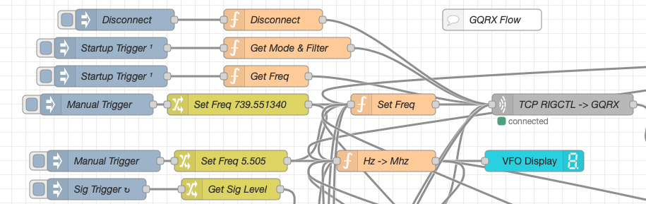
All the startup triggers feed information into the RIGCTL section of the GQRX flow. This section of the flow (shown below) passes all the commands onto the GQRX SDR software to control the SDR receiver.
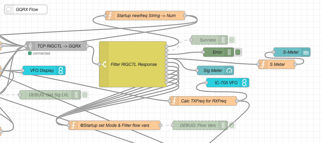
M0AWS Node-RED QO-100 Ground Station Dashboard – GQRX RIGCTL Flow
The TCP RIGCTL -> GQRX node is a standard TCP Request node that is configured to talk to the GQRX software on the defined IP Address and Port as configured in the GQRX setup. The output from this node then goes into the Filter RIGCTL Response node that processes the corresponding reply from GQRX for each message sent to it. Errors are trapped in the green Debug node and can be used for debugging.
The receive S Meter is also driven from the the output of the Filter RIGCTL Response node and passed onto the S Meter function for formatting before being passed through to the actual gauge on the dashboard.
Continuing down the left hand side of the flow we move into the section where all the GQRX controls are defined.
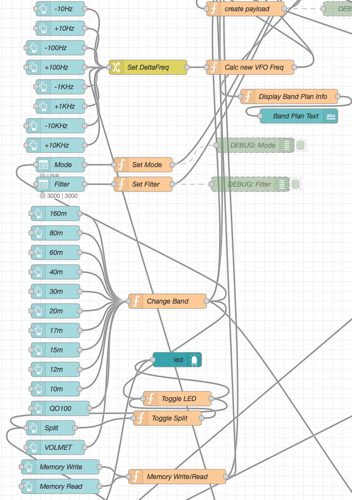
M0AWS Node-RED QO-100 Ground Station Dashboard – GQRX Controls Flow
In this section we have the VFO step buttons that move the VFO up/down in steps of 10Hz to 10Khz. Each button press generates a value that is passed onto the Set DeltaFreq change node and then on to the Calc new VFO Freq function. From here the new VFO frequency is stored and passed onto the communications channel to send the new VFO frequency to the GQRX software.
The Mode and Filter nodes are simple drop down menus with predefined values that are used to change the mode and receive filter width of the SDR receiver.
Below are the HAM band selector buttons, each of these will use a similar process as detailed above to change the VFO frequency to a preset value on each of the HAM HF Bands.
The QO-100 button puts the transmit and receive VFO’s into synchro-mode so that the receive VFO follows the transmit VFO. It also sets the correct frequency in the 739Mhz band for the downlink from the LNB in GQRX SDR software and sets the IC-705 to the correct frequency in the 2m VHF HAM band to drive the 2.4Ghz up-converter.
The Split button allows the receive VFO to be moved away from the transmit VFO for split operation when in QO-100 mode. This allows for the receive VFO to be moved away so that you can RIT into slightly off frequency stations or to work split when working DXpedition stations.
The bottom two Memory buttons allow you to store the current receive frequency into a memory for later recall.
At the top right of this section of the flow there is a Display Band Plan Info function, this displays the band plan information for the QO-100 satellite in a small display field on the Dashboard as you tune across the transponder. Currently it only displays information for the satellite, at some point in the future I will add the necessary code to display band plan information for the HF bands too.
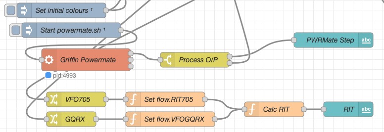
The final section of the GQRX flow (shown below) sets the initial button colours and starts the Powermate USB VFO knob flow. I’ve already written a detailed article on how this works here but, for completeness it is triggered a few seconds after startup (to allow the USB device to be found) and then starts the BASH script that is used to communicate with the USB device. The output of this is processed and passed back into the VFO control part of the flow so that the receive VFO can be manually altered when in split mode or in non-QO-100 mode.
M0AWS Node-RED QO-100 Ground Station Dashboard – Powermate VFO Flow
The bottom flows in the image above set some flow variables that are used throughout the flow and then calculates and sets the RIT value on the dashboard display.
The final section of the flow is the IC-705 control flow. This is a relatively simple flow that is used to both send and receive data to/from the IC-705, process it and pass it on to the other parts of the flow as required.
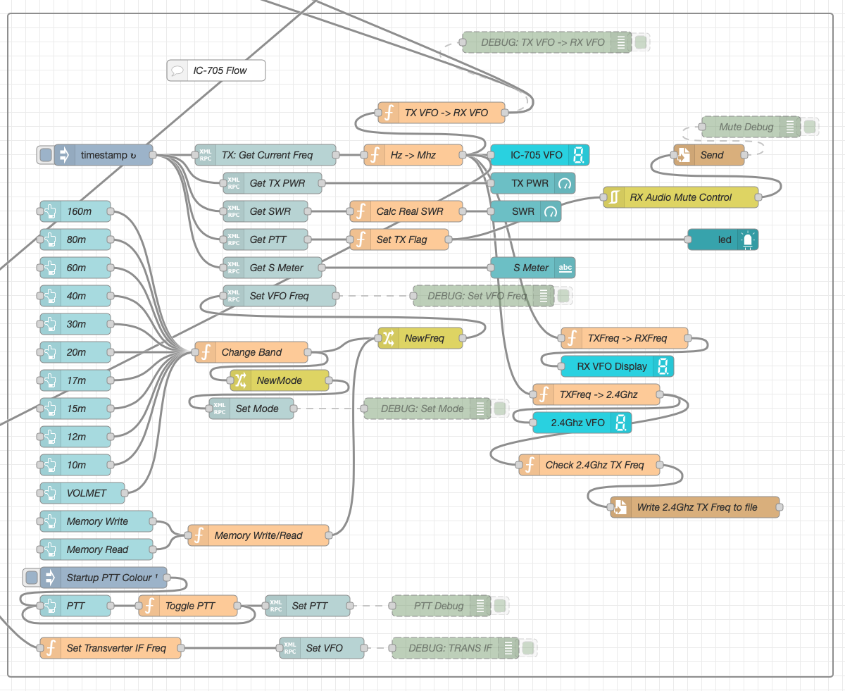
M0AWS Node-RED QO-100 Ground Station Dashboard – IC-705 Control Flow
The IC-705 flow is started via the timestamp trigger at the top left. This node is nothing more than a trigger that fires every 0.5 seconds so that the dashboard display is updated in near realtime. The flow is pretty self explanatory, in that it collects the current frequency, transmit power, SWR reading, PTT on/off status and S Meter reading each time it is triggered. This information is then processed and used to keep the dashboard display up to date and to provide VFO tracking information to the GQRX receive flow.
On the left are the buttons to change band on the IC-705 along with a button to tune to the VOLEMT on the 60m band. Once again there two memory buttons to save and recall the IC-705 VFO frequency.
The Startup PTT Colour trigger node sets the PTT button to green on startup. The PTT button changes to red during transmit and is controlled via the Toggle PTT function.
At the very bottom of the flow is the set transverter IF Freq function, this sets the IC-705 to a preselected frequency in the 2m HAM band when the dashboard is switched into QO-100 mode by pressing the QO-100 button.
On the right of the flow there is a standard file write node that writes the 2.4Ghz QO-100 uplink frequency each time it changes into a file that is used by my own logging software to add the uplink frequency into my log entries automatically. (Yes I wrote my own logging software!)
The RX Audio Mute Control filter node is used to reduce the receive volume during transmit when in QO-100 full duplex mode otherwise, the operator can get tongue tied hearing their own voice 250ms after they’ve spoken coming back from the satellite. This uses the pulse audio system found on the Linux platform. The audio is reduced to a level whereby it makes it much easier to talk but, you can still hear enough of your audio to ensure that you have a good, clean signal on the satellite.
As I said at the beginning of this article, this flow has grown organically over the last 12 months and has been a fun project to put together. I’ve had many people ask me how I have created the dashboard and whether they could do the same for their ground station. The simple answer is yes, you can use this flow with any kind of radio as long as it has the ability to be controlled via CAT/USB or TCP/IP using XMLRPC or RIGCTL.
To this end I include below an export of the complete flow that can be imported into your own Node-RED flow editor. You may need to make changes to it for it to work with your radio/SDR but, it shouldn’t take too much to complete. If like me you are using an IC-705 and any kind of SDR controlled by GQRX SDR software then it’s ready to go without any changes at all.
A couple of years ago I built a Matrix Synapse server and connected it to the decentralised global Matrix chat network that is federated world wide by enthusiasts who host their own Matrix servers. Due to the enthusiasm for a decentralised network the Matrix has grown exponentially and is now an established force in the world of Opensource global communication services.
When I built my server and configured it online my aim was to bring together an enthusiastic group of Radio Amateurs (Radio HAMs) who could build a friendly, welcoming community where people could share, learn and have fun with other liked minded individuals without all the nonsense you see on commercial social media platforms.
Overtime we’ve increased the number of rooms available in the HAM Radio space and the number of subjects covered. This has grown organically as our community has grown and we’ve ventured together into new areas of the hobby.
Global Matrix Ham Radio Space hosted on the M0AWS Matrix Server
From the community a number of projects have spawned including the Opensource.radio Wiki that Mike, DK1MI is sponsoring that aims to detail all the Opensource HAM Radio software, Hardware and projects in one centralised site on the internet. This is a great project and one I am very happy to contribute to.
Thanks to Mike, DK1MI we now also have our own Matrix AllStarLink node available. This is a great resource for the community as it is often not possible for all of us to communicate via the radio waves due to geo-location, time zones, local planning regulations etc. Having this 24/7 internet based resource makes it a lot easier for the community to chat at any time even when propagation on the HF bands isn’t in our favour.
We also have a very active satellite room with regular nets on the QO-100 satellite. With such a great range of rooms and subjects there’s plenty to read and talk about with the community.
If you fancy being part of this growing, enthusiastic group of Radio Amateurs and Short Wave Listeners (SWLs) then click on the link below and come and say hello, a warm welcome awaits!
I get quite a few emails from readers of my blog asking how my QO-100 satellite station is put together and so, I thought perhaps now is a good time to put together an article detailing the complete build.
My QO-100 satellite ground station is built around my little Icom IC-705 QRP transceiver, it’s a great little rig and is ideal for the purpose of driving a 2.4Ghz transverter/up-converter.
Of course all the software used for the project is Opensource and freely available on the internet.
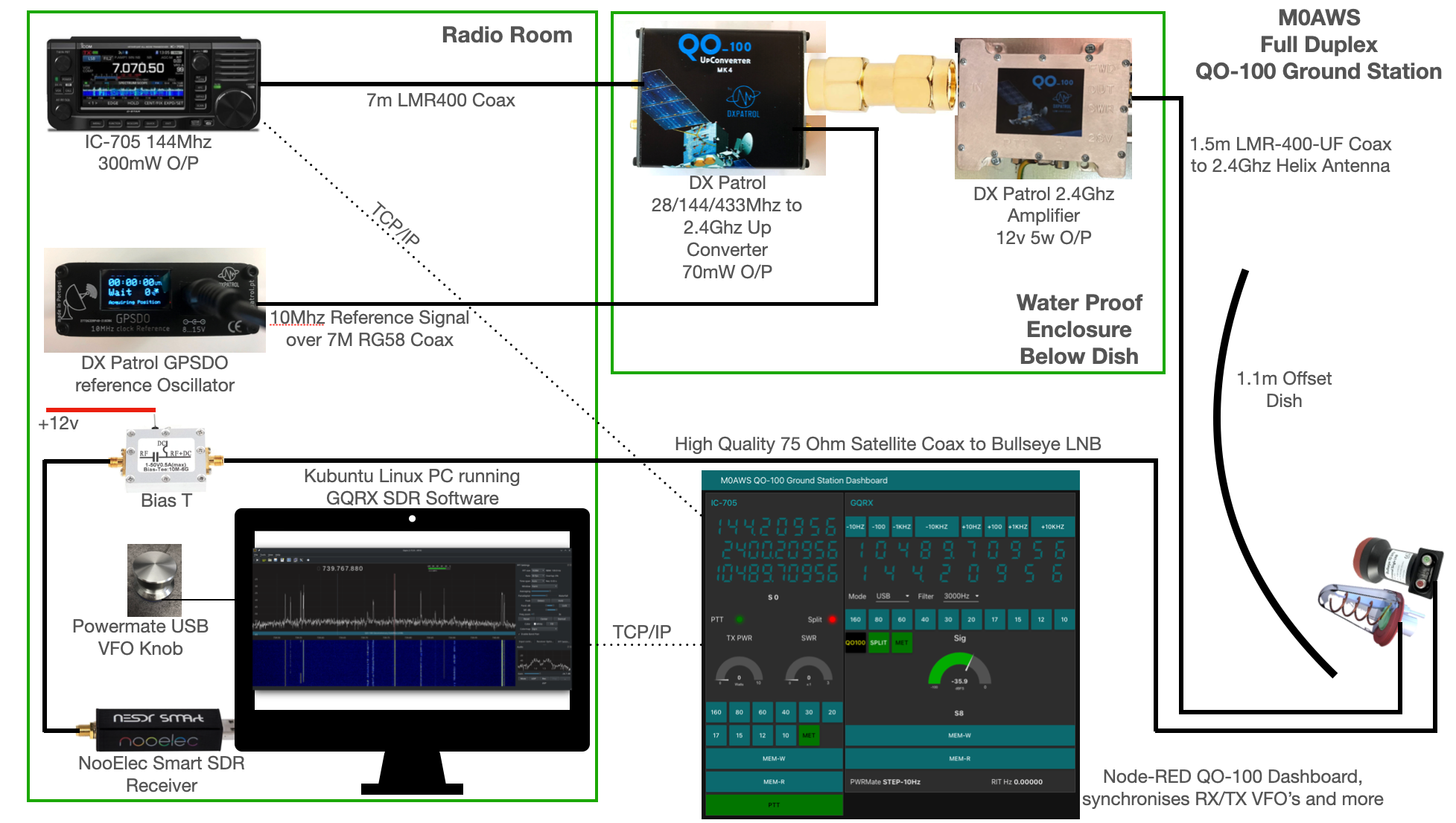
M0AWS QO-100 Ground Station Build Visual (Click to Enlarge)
The station comprises of the following building blocks:
QO-100 Ground Station Dashboard developed using Node-RED
LMR400-UF/RG58 Coax Cable
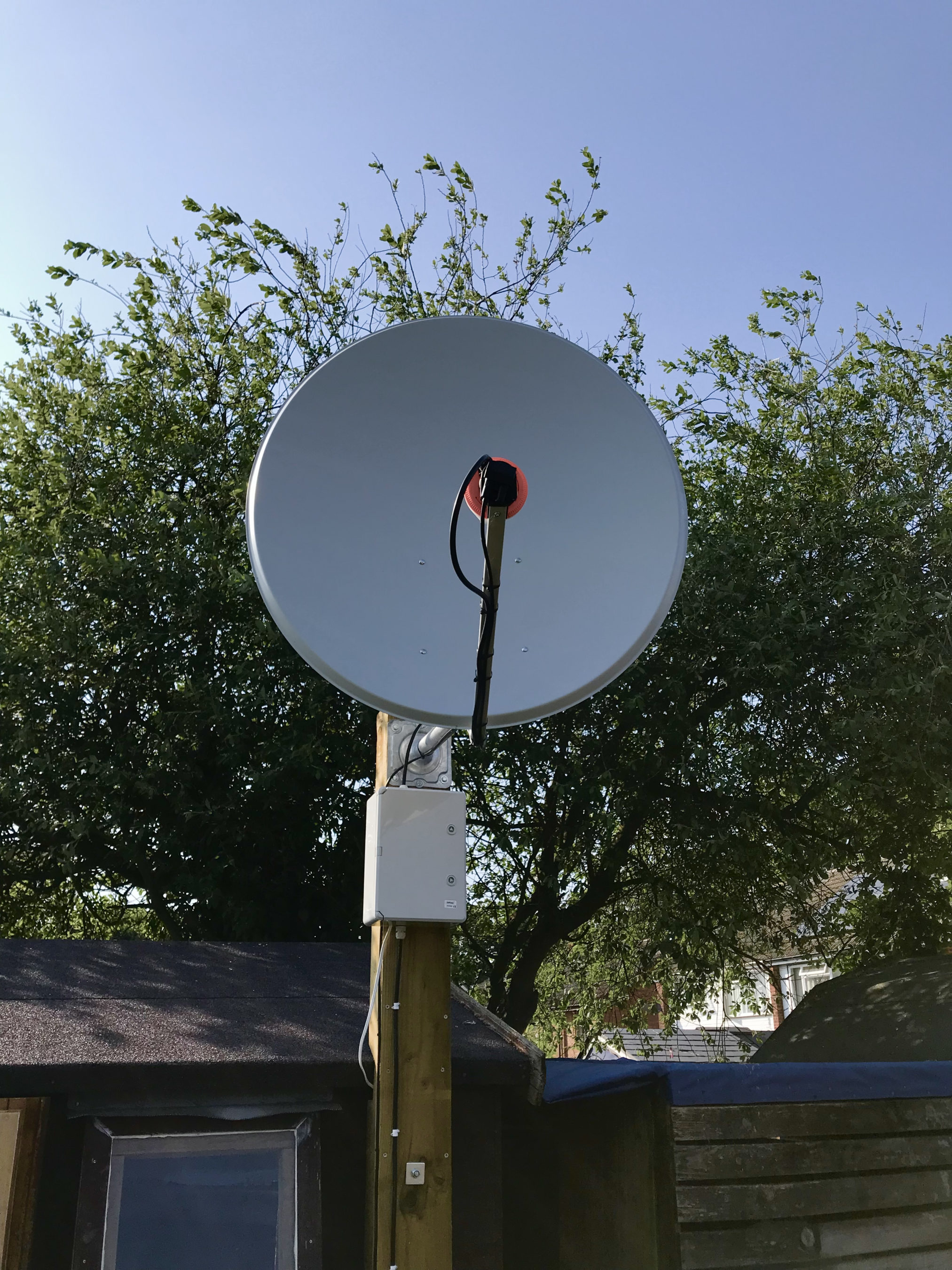
M0AWS QO-100 1.1m (110cm) off-set Dish with IceCone Helix antenna and Bullseye LNB.
To get a good clear view of the QO-100 satellite I have the dish mount 3.2m above the ground. This keeps it well clear of anyone walking past in the garden and beams the signal up at an angle of 26.2 degrees keeping well clear of neighbouring gardens.
The waterproof enclosure below the dish houses all the 2.4Ghz equipment so that the distance between the feed point and the amplifier are kept to a minimum.
The DXPatrol amplifier is spec’d to run at 28v/12w or 12v/5w, I found that running it at 28v produced too much output for the satellite and would cause the LEILA alarm on the satellite to trip constantly. Running the amp at 12v with a maximum of 5w output (average 2.5-3.5w) is more than enough for me to have a 5/9+10 signal on the transponder.
The large 1.1m dish gives me quite an advantage on receive enabling me to hear the very weak stations with ease compared to other stations.
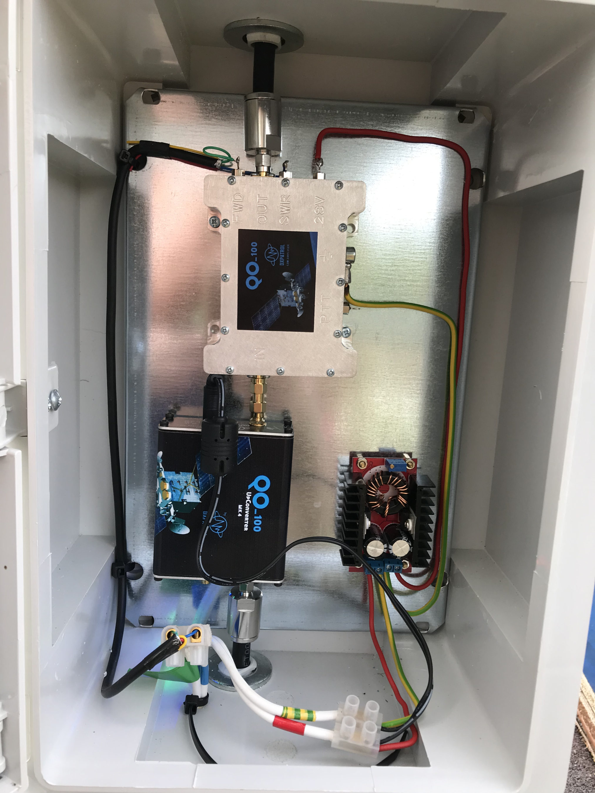
2.4Ghz ground station enclosure ready for testing
The photo above shows the 2.4Ghz equipment mounted in the waterproof enclosure below the dish. This photo was taken during the initial build phase before I rewired it so, the amplifier is shown connected to the 28v feed. To rewire the amp to 12v was just a matter of removing the 28v converter and connecting the amp directly to the 12v feed instead. This reduced the output from a maximum of 12w down to a maximum of 5w giving a much better (considerate) level on the satellite.
It’s important to keep all interconnects as short as possible as at 2.4Ghz it is very easy to build up a lot of loss between devices.
For the connection from the IC-705 to the 2.4Ghz Up-Converter I used a 7m run of LMR-400 coax cable. The IC-705 is set to put out just 300mW on 144Mhz up to the 2.4Ghz converter and so it’s important to use a good quality coax cable.
Once again the output from the 2.4Ghz amplifier uses 1.5m of LMR-400-UF coax cable to feed up to the 2.2 turn Icecone Helix Antenna mounted on the dish. This keeps loss to a minimum and is well worth the investment.
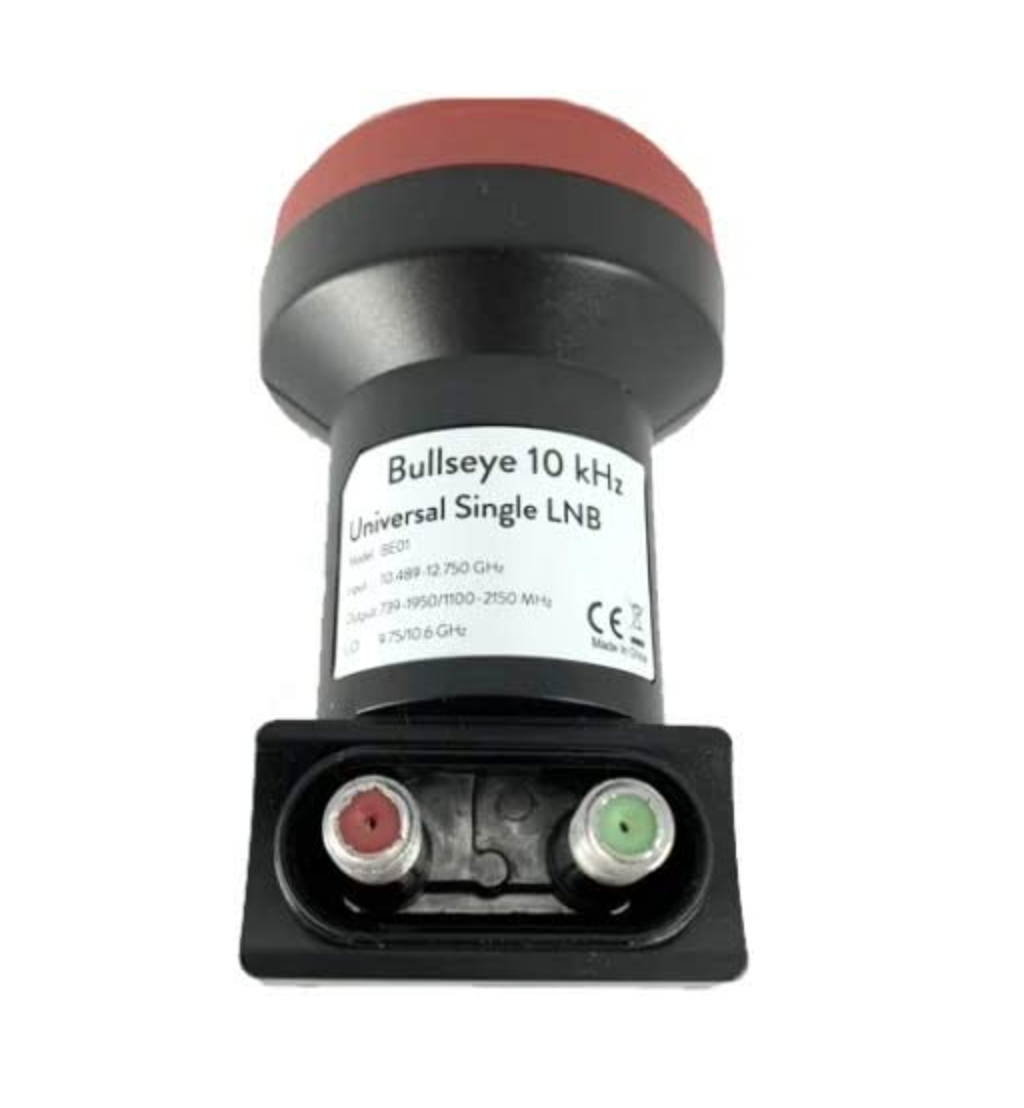
Bullseye 10Khz High Stability Unversal Single LNB for 10.489-12.750Ghz
The receive path starts with a Bullseye LNB, this is a high gain LNB that is probably one of the best you could use for QO-100 operations. It’s fairly stable frequency wise but, does drift a little in the summer months with the high temperature changes but, overall it really is a very good LNB.
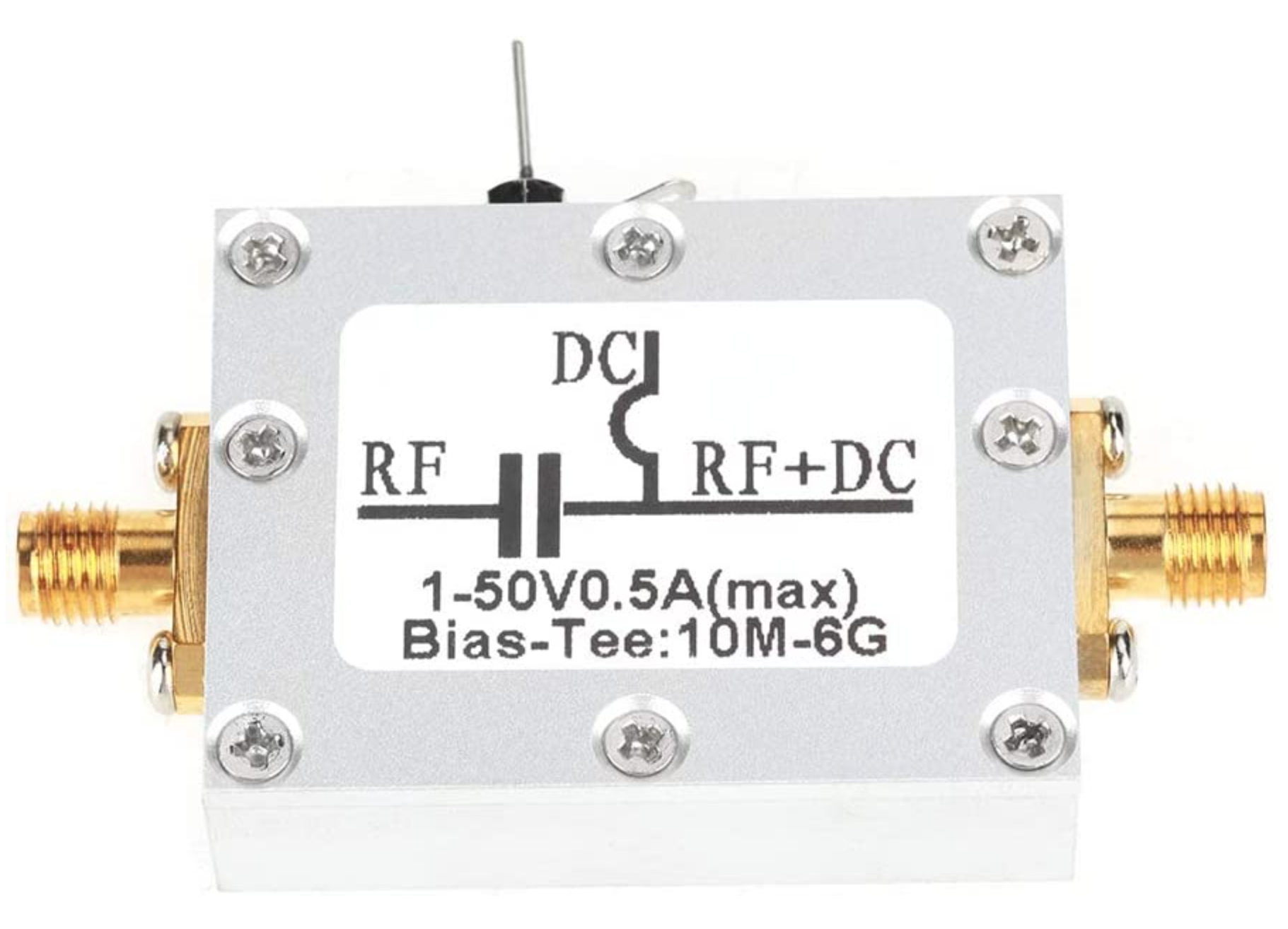
The 12v feed to the LNB is via the coax and is injected by the Bias-T device that is in the radio shack. This 12v feed powers the LNA and associated electronics in the LNB to provide a gain of 50-60dB.
Bias-T to inject 12v feed into the coax for the Bullseye LNB
From the Bias-T the coax comes down to the NooElec SmartSDR receiver. This is a really cheap SDR device (<£35 on Amazon) based on the RTL-SDR device but, it works incredibly well. I originally used a Funcube Dongle Pro+ for the receive side however, it really didn’t handle large signals very well and there was a lot of signal ghosting so, I swapped it out for the NooElec SDR and haven’t looked back since.
The NooElec SmartSDR is controlled via the excellent Opensource software GQRX SDR. I’ve been using GQRX SDR for some years now and it’s proven itself to be extremely stable and reliable with support for a good number of SDR devices.
To enhance the operation of the SDR device I have added a Griffin Powermate VFO knob to the build. This is an old USB device that I originally purchased to control my Flex3000 transceiver but, since I sold that many moons ago I decided to use it as a VFO knob in my QO-100 ground station. Details on how I got it working with the station are detailed in this blog article.
Having the need for full duplex operation on the satellite this complicates things when it comes to VFO tracking and general control of the two radios involved in the solution and so I set about creating a QO-100 Dashboard using the great Node-RED graphical programming environment to create a web app that simplifies the management of the entire setup.
M0AWS QO-100 ground Station Control Dashboard built using Node-RED.
The QO-100 Dashboard synchronises the transmit and receive VFO’s, enables split operation so that you can transmit and receive on different frequencies at the same time and a whole host of other things using very little code. Most of the functionality is created using standard Node-RED nodes. More info on Node-RED can be found on the Opensource.radio Wiki or from the menu’s above.
I’ll be publishing an article all about the QO-100 Dashboard in the very near future along with a downloadable flow file.
I’m extremely pleased with how well the ground station works and have had well in excess of 500 QSO’s on the QO-100 satellite over the last last year.
With the recent explosion of artificial intelligence (AI) art generators that are making the news of late for all the wrong reasons, I decided to see if I could put it to good use and design some futuristic QSL cards.
Having recently been contacted by the Special Callsigns QSL Manager and being advised that there were 18 QSL cards waiting for me, I decided it was time to create some QSL cards of my own for future use.
Having never used any form of online AI and not having any artistic abilities I was amazed how easy it was to create images using nothing more than a paragraph or so of text to describe what it was I wanted to create.
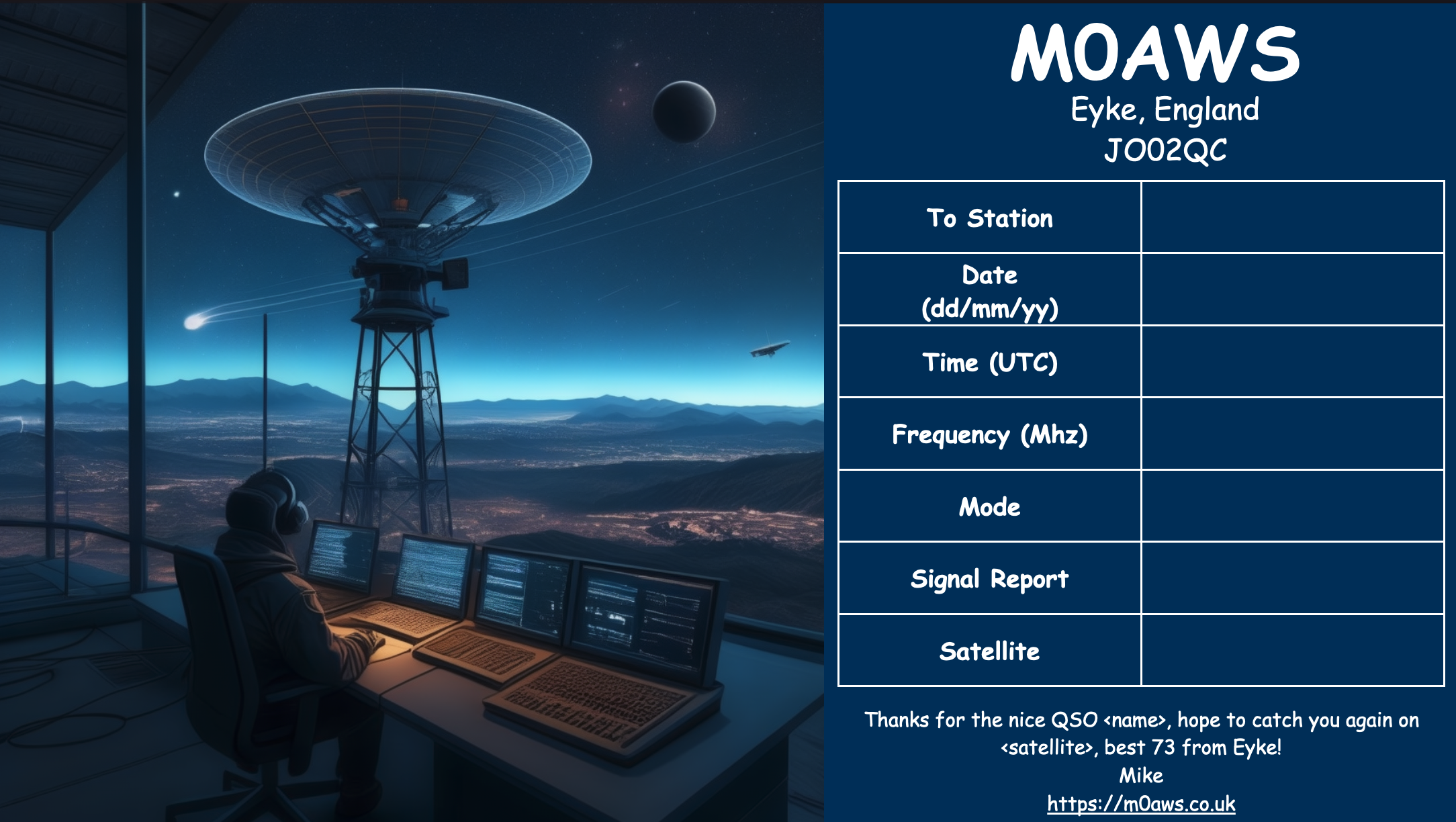
Since all the QSL cards I received were for contacts on the QO-100 satellite, I set out to create a visually futuristic QSL card that was based around a radio HAM operator and satellite communications.
M0AWS – 1st attempt at creating a futuristic QSL card image using AI Art
To my surprise the results of my first image generation were surprisingly good. The AI generated an image that resembled the simple text that I entered, although I never requested a one legged HAM operator!
Pleased with my very first attempt I gradually improved the description of what I was looking for, adding more and more detail to the text and including things that I wanted to see in the image. Over a fairly short period of time this approach started to generate some very interesting images.
M0AWS – AI Art QSL Image attempt 2M0AWS – AI Art QSL Image attempt 3M0AWS – AI Art QSL Image attempt 4
With each iteration I gradually got closer to what I was trying to achieve but, never quite got exactly what I wanted so, I decided to rewrite the descriptive text adding even more information than before. The text was now a full blown paragraph with quite specific things described including the angle at which the scene was being viewed from.
The other option I wanted to try out was the theme functionality that the AI offered. This allows you to set a theme for the image from things like steampunk, cartoon, manga, real world and many more. The results were quite impressive and added yet another angle to the image generation.
M0AWS – AI Art QSL Theme 1M0AWS – AI Art QSL Theme 3M0AWS – AI Art QSL Theme 2
I disappeared down the theme AI Art generation rabbit hole for quite some time and generated some very interesting and fun results. The best by far though was the Thunderbirds themed image, this did put a smile on my face!
M0AWS – AI Art QSL Thunderbirds Themed
At the other end of the spectrum I tried the Salvador Dalli theme, it produced an image that was very like the work of the famous artist but, wasn’t quite what I was looking for.
M0AWS – AI Art QSL Salvador Dalli Themed
After much fun I eventually settled on the image I was after, a futuristic scene of a radio HAM with a satellite ground station over looking a mountain range and city below.
M0AWS Satellite QSL Card generated using online AI
I’m really pleased with the results from my ventures into AI generated art. The next challenge is to create a QSL card for HF bands Contacts.
This solution has worked incredibly well from the outset and over time I’ve added extra functionality that I’ve found to be useful to enhance the overall setup.
The latest addition to the ground station solution is a Sennheiser Headset that I picked up for just £56 on Amazon (Much cheaper than the Heil equivalents at the HAM stores!) and have found it to be excellent. The audio quality from both the mic and the headphones is extremely good whilst being light and comfortable to wear for extended periods.
M0AWS – Sennheiser SC 165 Headset
To incorporate this into the ground station the headset is connected to my Kubuntu PC and the audio chain to the IC-705 is sent wirelessly using the latest version of WFView. This works extremely well. The receive audio comes directly from the GQRX SDR software to the headphones so that I have a full duplex headset combination.
Audio routing is done via pulse audio on the Kubuntu PC and is very easy to setup.
Since I no longer have a mic connected to the IC-705 directly I found that I needed a way to operate the PTT wirelessly and this is where the latest addition to my NodeRed QO-100 Dashboard comes in.
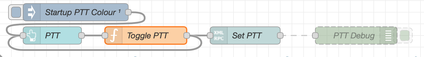
Adding a little functionality to the NodeRed flow I was able to create a button that toggles the IC-705 PTT state on and off giving me the ability to easily switch between receive and transmit using a simple XMLRPC node without the need for a physical PTT button.
M0AWS – Additional NodeRed PTT Flow
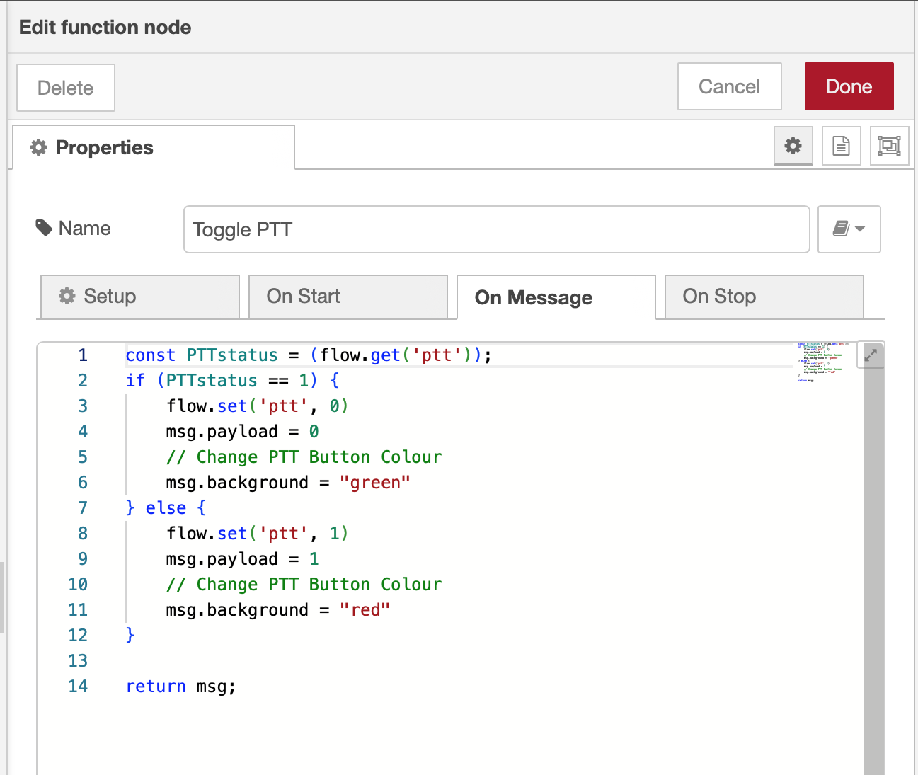
The PTT state and PTT button colour change is handled by the Toggle PTT function node shown in the above flow. The code to do this is relatively simple as shown below.
M0AWS – NodeRed Toggle PTT Function to change button colour
The entire QO-100 Dashboard flow has grown somewhat from it’s initial conception but, it provides all the functionality that I require to operate a full duplex station on the QO-100 satellite.
M0AWS – NodeRed QO-100 Dashboard complete flow
This simple but, effective PTT solution works great and leaves me hands free whilst talking on the satellite or the HF bands when using the IC-705. This also means that when using my IC-705 it only requires the coax to be connected, everything else is done via Wifi keeping things nice and tidy in the radio shack.
M0AWS – Updated NodeRed QO-100 Dashboard with PTT button
The image above shows the QO-100 ground station in receive cycle with the RX/TX VFO’s in split mode as the DX station was slightly off frequency to me. The PTT button goes red when in TX mode just like the split button shown above for visual reference.
As you can probably tell, I’m a huge fan of NodeRed and have put together quite a few projects using it, including my HF Bands Live Monitoring web page.
Since I’ve been using my Icom IC-705 on the QO-100 satellite I’ve been getting no end of unsolicited great audio reports with one Op even saying I have the best audio he’s ever heard on the satellite.
Most people are surprised when I tell them that I am using the stock fist mic that comes with the radio. It’s nothing special, in fact it’s rather cheap and plastic, not particularly good quality however, it does seem to have a good sounding mic insert.
The other great thing about the IC-705 is that it has a two channel parametric equaliser built into the radio. Many people don’t realise this and miss out on the massive improvement they can make to their transmitted audio with just a few simple adjustments.
The stock fist mic has a very flat response across the audio frequency range out of the box and doesn’t sound particularly inspiring. Many see this as a negative and often just replace the mic with either a headset (probably from Heil), a boom mic (again probably from Heil) or another, better quality fist mic. All of these options cost varying amounts of money when in reality none of them are necessary.
Starting from a flat audio response is actually a good thing as it makes the equaliser adjustments more pronounced, making it easier to adjust the settings to suit your voice.
We all have different voices but, there is one thing that is pretty much the same for everyone and that’s the frequency range in which the articulation of the words and sounds we make can be found. It’s this part of the voice that is often lacking when we struggle to understand what the DX station is saying.
It’s become common place on the HAM bands these days for stations to boost the bass frequencies and reduce the mid and high frequencies with the net result of a horrible bass ringing sound and muddy mid range often making it very difficult to understand what is being said.
Having spent some considerable time watching the great videos on audio from the late Bob Heil, K9EID it’s clear that the most important frequencies to enhance are those around 2.5khz as this is where all the articulation is in the human voice.
To this end I set about setting up the audio on my IC-705 QRP radio so that my voice sounded such that it is easy to comprehend even in the most difficult of situations on air. This doesn’t mean that it has to be very harsh and overly bright, quite the opposite in that to be heard clearly in all conditions on air one’s audio needs to be balanced across the frequency range with an enhancement in the 2.5Khz frequency range.
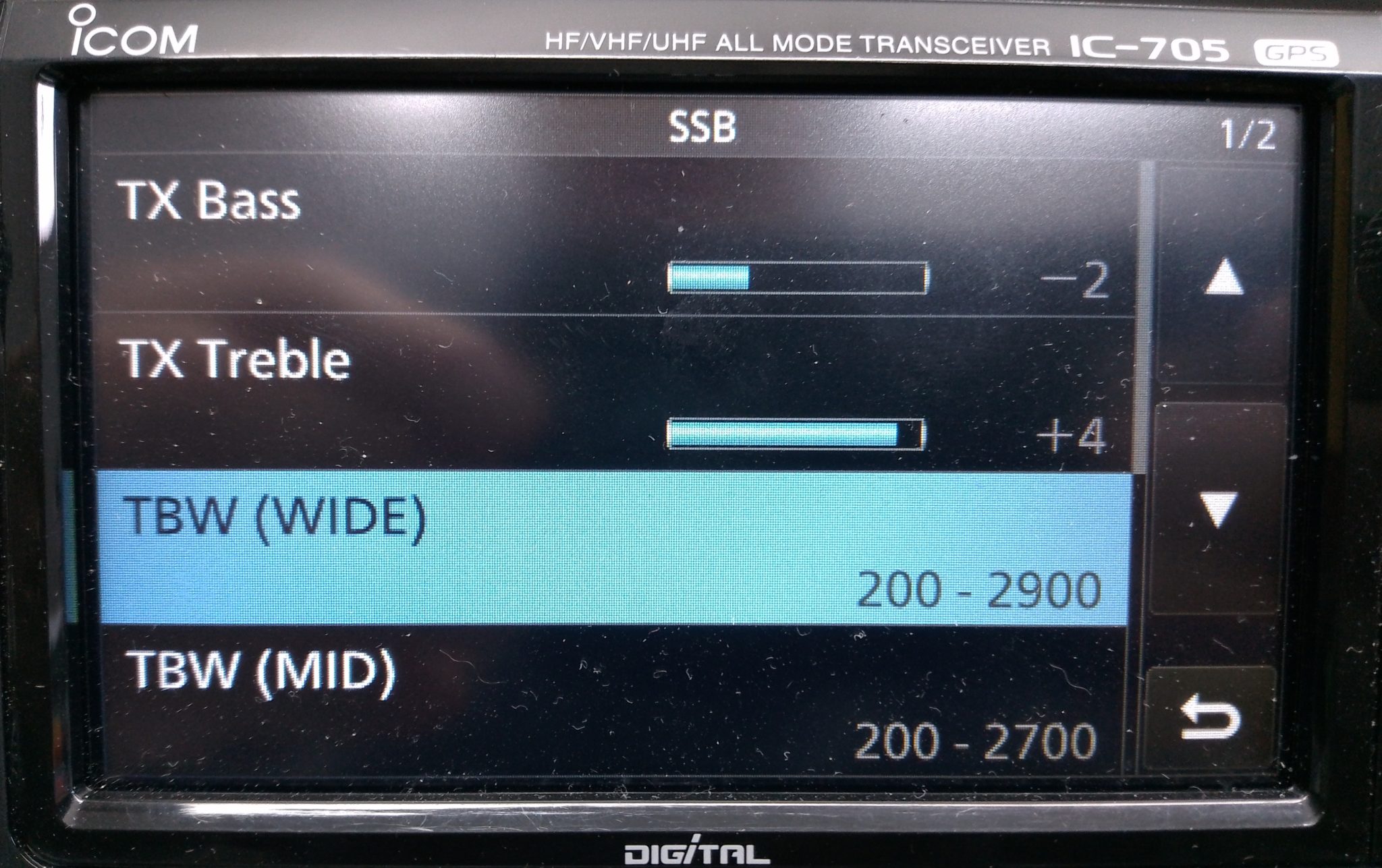
M0AWS IC-705 Transmit audio settings – part 1
To reduce the unwanted, muddy bass the first thing to do is change the transmit bandwidth for the “Wide” setting to 200-2900Hz. This will cut off the bottom 100Hz from the voice reducing the overall bass output from the standard fist mic that comes with the radio. This will ensure a 2700Hz wide SSB signal, the recommended max for QO-100 operations and the preferred bandwidth on the HF bands.
On top of this I made a further reduction of 2dB on the TX Bass setting to help balance out the overall audio response of the mic insert.
Next I set about enhancing the higher frequency response of the mic insert and found that it required an increase of 4dB to bring out the articulation of my voice. This enhanced my audio considerably compared to the standard output from the fist mic and improved the intelligibility of my voice considerably, especially in difficult band conditions.
To complete the setup I set the compression to 3 and mic gain to 35 so that the overall drive level is increased slightly giving a greater average output from the radio.
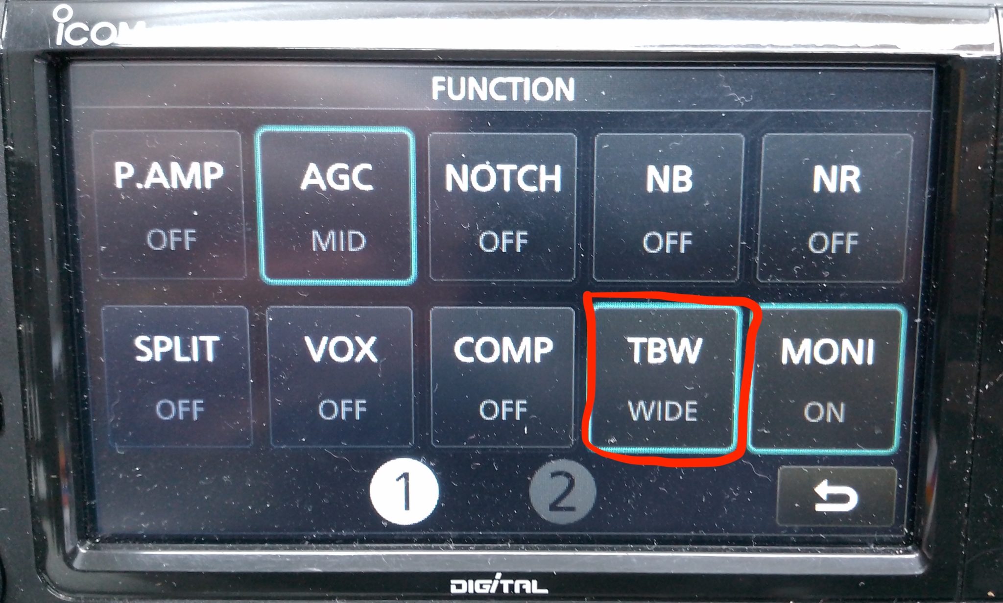
M0AWS IC-705 Audio Settings – part 2
Once I’d got the audio setup correctly I enabled the configuration by setting the Transmit Bandwidth (TBW) to the “Wide” config in the IC-705 Function menu so that the correct settings were made active.
Ever since making these relatively easy changes I have had no end of unsolicited great audio reports from stations asking me what mic I am using and how I’ve managed to get such good audio from the IC-705. Many are surprised that I am using the OEM fist mic that comes with the radio and I’m sure there are those who don’t believe me!
Of course all voices are slightly different and these settings may not be perfect for your voice but, all those that have tried these settings have told me that their audio sounds better than ever and that DX stations often comment on how good their audio is.
I also went through the same exercise with my Yaesu FTDX10 with it’s standard fist mic and again achieved excellent results with it’s 3 channel parametric equaliser. I’ll go through the somewhat more complicated setup for the FTDX10 in another article soon.
I’ve got a couple of old RaspberryPi computers on the shelf in the shack and so decided it was time for me to put one of them to good use. The first model on the shelf is the oldest and is one of the very first RaspberryPi 1 computers that was released. (It’s the one with the yellow analog video signal output on the board!). This particular model is extremely slow but, I hang onto it just as a reminder of the first SBC in the line.
The second one is a RaspberryPi 2, a quad core machine that is only slightly faster than the first model but, it’s powerful enough to run HAM Clock.
It didn’t take long to install a vanilla Raspbian Desktop O/S and get it configured on the local LAN. I installed a few packages that I like to have available on all my Linux machines and then started on the HAM Clock install.
The first thing I needed to do was install the X11 development library that is required to compile the HAM Clock binary. To do this, open a terminal and enter the command below to install the package.
sudo apt install libx11-dev
You will need to type in your password to obtain root privileges to complete the installation process and then wait for the package to be installed.
The HAM Clock source code is available from the HAM Clock Website under the Download tab in .zip format. Once downloaded unzip the file and change directory into the ESPHamClock folder ready to compile the code.
cd ~/Downloads/ESPHamClock
Once in the ESPHamClock directory you can run a command to get details on how to compile the source code.
make help
This will check your system to see what screen resolutions are available and then list out the options available to you for compiling the code as shown below.
The following targets are available (as appropriate for your system)

    hamclock-800x480          X11 GUI desktop version, AKA hamclock
    hamclock-1600x960         X11 GUI desktop version, larger, AKA hamclock-big
    hamclock-2400x1440        X11 GUI desktop version, larger yet
    hamclock-3200x1920        X11 GUI desktop version, huge

    hamclock-web-800x480      web server only (no display)
    hamclock-web-1600x960     web server only (no display), larger
    hamclock-web-2400x1440    web server only (no display), larger yet
    hamclock-web-3200x1920    web server only (no display), huge

    hamclock-fb0-800x480      RPi stand-alone /dev/fb0, AKA hamclock-fb0-small
    hamclock-fb0-1600x960     RPi stand-alone /dev/fb0, larger, AKA hamclock-fb0
    hamclock-fb0-2400x1440    RPi stand-alone /dev/fb0, larger yet
    hamclock-fb0-3200x1920    RPi stand-alone /dev/fb0, huge
For my system 1600×960 was the best option and so I compiled the code using the command as follows.
make hamclock-1600x960
It’s no surprise that it takes a while to compile the code on such a low powered device. I can’t tell you how long exactly as I went and made a brew and did a few other things whilst it was running but, it took a while!
Once the compilation was complete you then need to install the application to your desktop environment and move the binary to the correct directory.
make install
Once the install is complete there should be an icon on the GUI desktop to start the app. If like mine it didn’t create the icon then you can start the HAM Clock by using the following command in the terminal.
/usr/local/bin/hamclock &
The first time you start the app you’ll need to enter your station information, callsign, location etc and then select the settings you want to use. There are 4 pages of options for configuring the app all of which are described in the user documentation.
M0AWS – HAM Clock running on RaspberryPi Computer
Once the configuration is complete the map will populate with the default panels and data. I tailored my panels to show the items of interest to me namely, POTA, SOTA, International Beacon Project and the ISS space station track. I was hoping to be able to display more than one satellite at a time on the map however, the interface only allows for one bird to be tracked at a time.
You can access the HAM Clock from another computer using a web browser pointed at your RaspberryPi on your local LAN using either the IP address or the hostname of the device.
http://<hostname>:8081/live.html

or

http://<ip-address>:8081/live.html
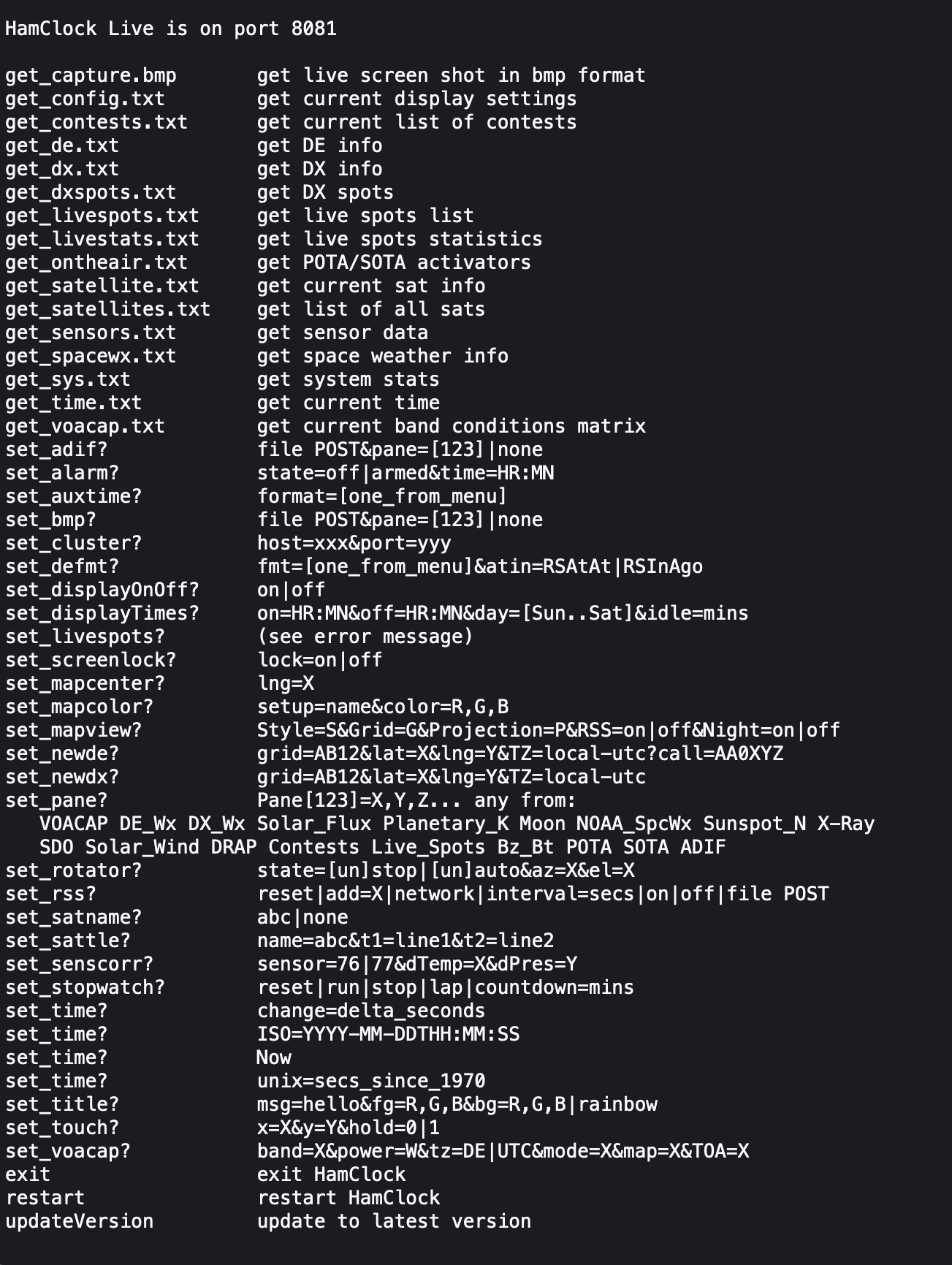
You can also control the HAM Clock remotely via web browser using a set of web commands that are detailed on port 8080 of the device.
http://<hostname or ip-address>:8080/
M0AWS – HAM Clock remote command set
This is a great addition to any HAM shack especially if, like me you have an old HDTV on the wall of the shack that is crying out to display something useful.
More soon …
We use cookies to ensure that we give you the best experience on our website. If you continue to use this site we will assume that you are happy with it.Ok