
The bi-directional slot fed HF antenna isn’t mentioned very often these days for some strange reason. It’s a real shame as it is an excellent antenna that gives high gain through the loop between the frequencies of 14Mhz and 29Mhz.
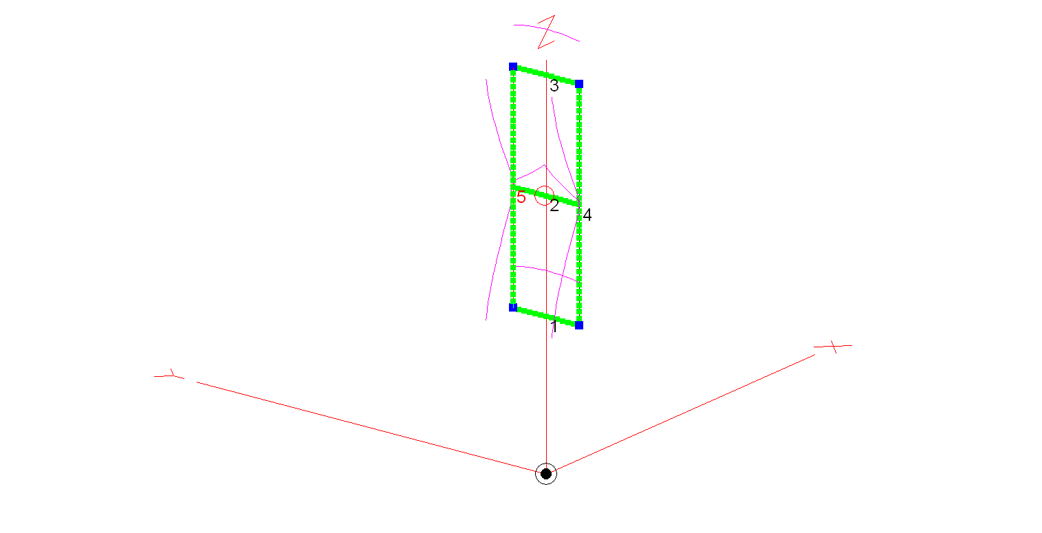
Construction of the antenna is relatively simple, 3 x 3m long horizontal wires and 2 x 9.2m long vertical wires. I’ve modelled the antenna using 20mm diameter copper tubing for the horizontal conductors and 2.5mm wire for the two vertical conductors. Using the 20mm copper tubing provides a rigid platform for the mounting of the antenna on a non-conductive mast whilst reducing weight by using 2.5mm wire for the vertical conductors. You could of course use 20mm copper tubing for all the conductors if you have a non-conductive mast that can handle the weight.
An alternative option is to hang the antenna from a high tree and secure it in position with non-conductive nylon cord. This works very well and makes it extremely easy to manually rotate.
The antenna is fed at the centre of the middle horizontal tube (conductor 2 in the image above) using one of the following methods:
Method 1 – Use a 4:1 Balun and ATU either in the radio/Radio Shack or connected directly to the Balun. Connecting a remote auto ATU to the balun directly at the feed point is the best option as you will then have a perfect 50 Ohm impedance match to the coax cable going back to the radio. (I’ve used my AH-705 and a 4:1 Balun at the feed point in the past with excellent results).
Method 2 – Connect a remote auto ATU directly to the feed point of the antenna and then 50 Ohm coax back to the radio shack. This will provide a perfect SWR match on all bands and works extremely well. (I’ve used my AH-705 remote auto ATU in this configuration as well in the past, again with excellent results and no discernible difference to method 1).
Method 3 – Feed the antenna with 450 Ohm open ladder line and use a 4:1 Balun and ATU in the radio shack to match the antenna to 50 Ohm radios. It’s important to bring the 450 Ohm ladder line away from the feed point horizontally and not vertically downwards. This will then help to protect the radiation pattern.
Looking at the 2D Far Field Plots this antenna provides excellent gain at relatively low radiation angles on all bands 20m – 10m making it an ideal antenna for chasing DX.
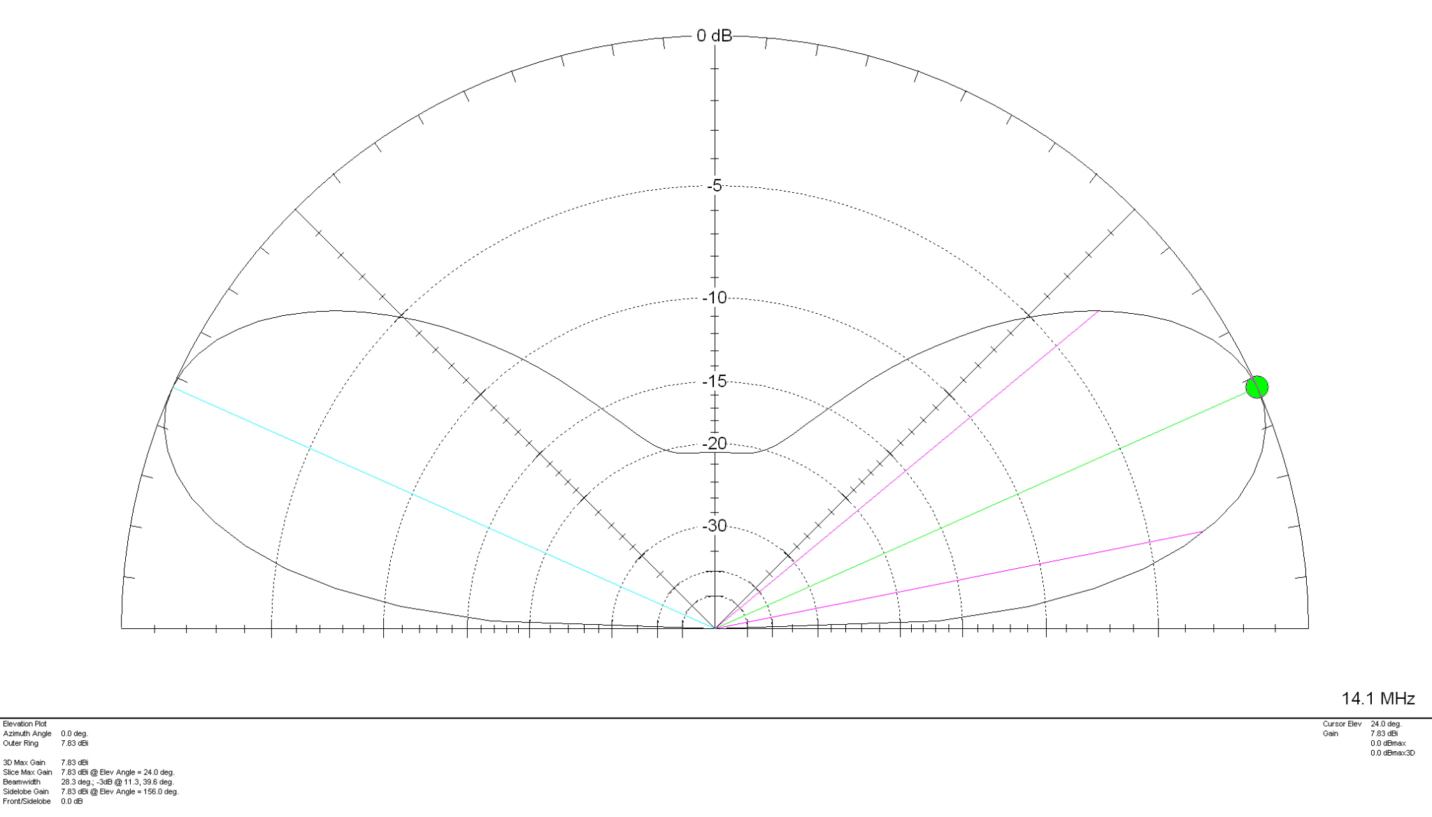
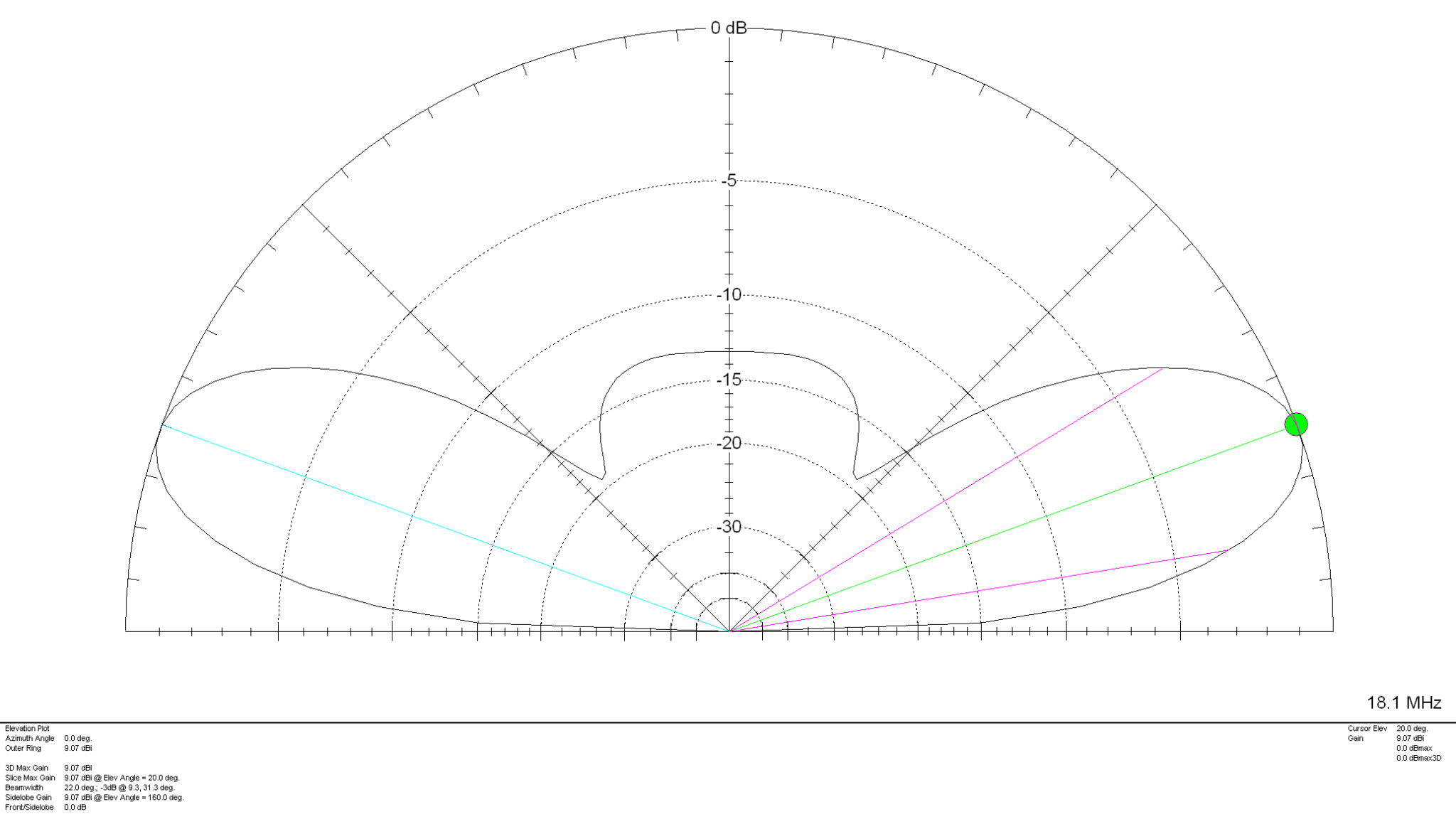
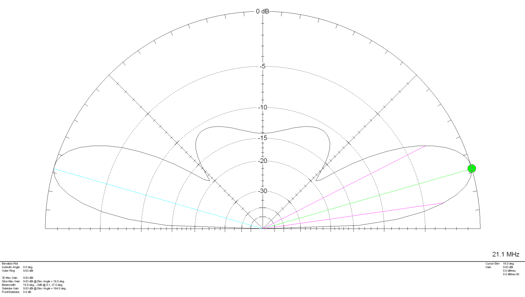
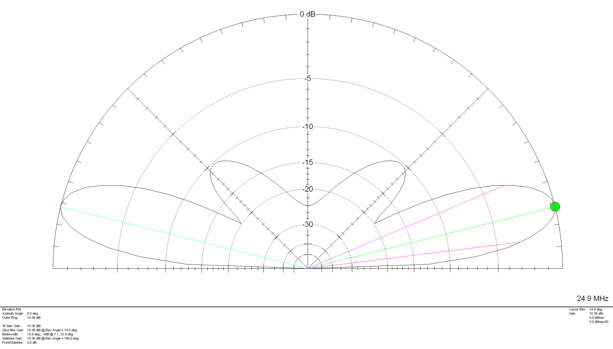
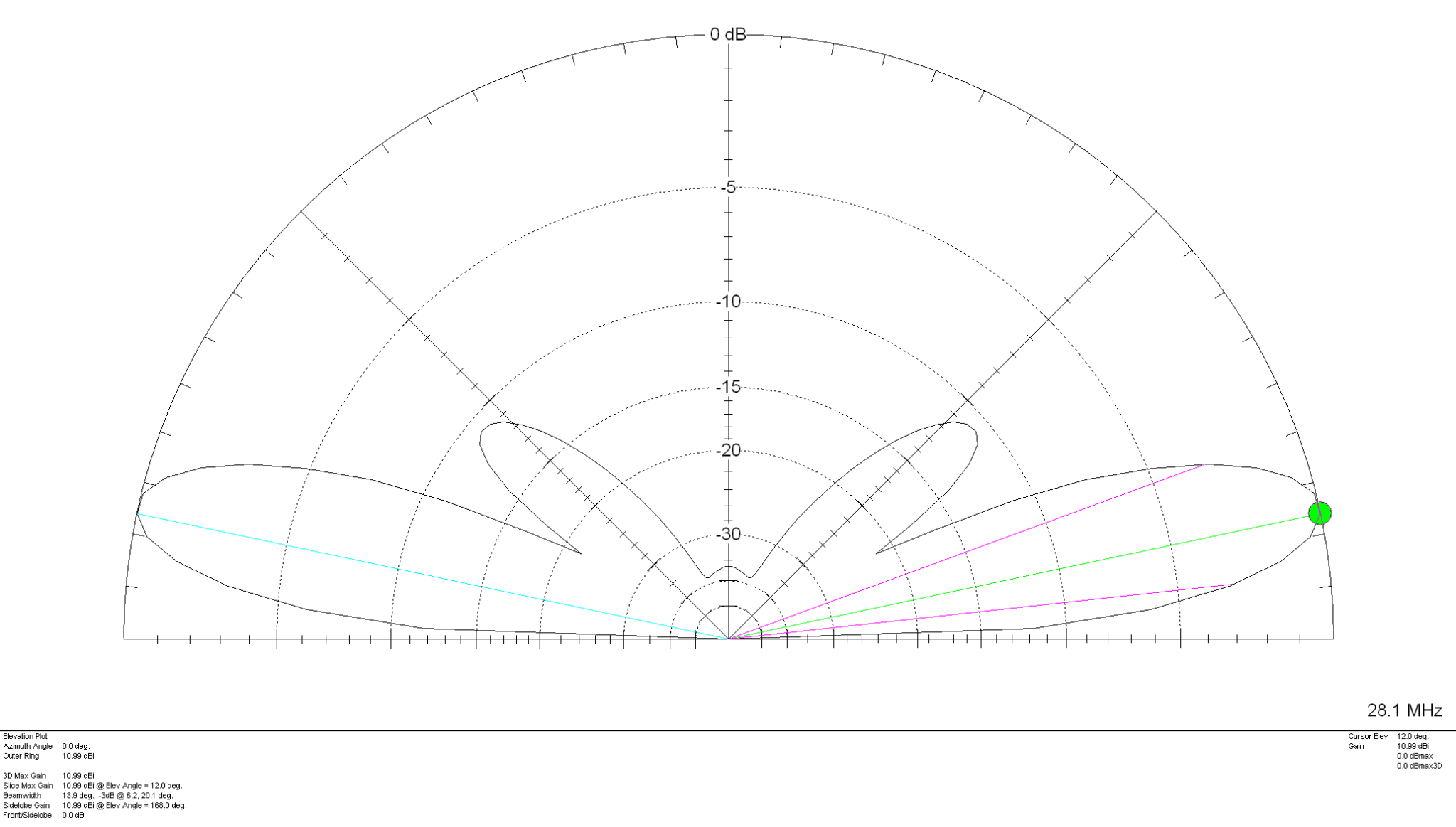
The gain on each band is as follows:
20m Band – 7.83dBi at 24 Degrees
17m Band – 9.07dBi at 20 Degrees
15m Band – 9.63dBi at 16 Degrees
12m Band – 10.36dBi at 14 Degrees
10m Band – 10.99dBi at 12 Degrees
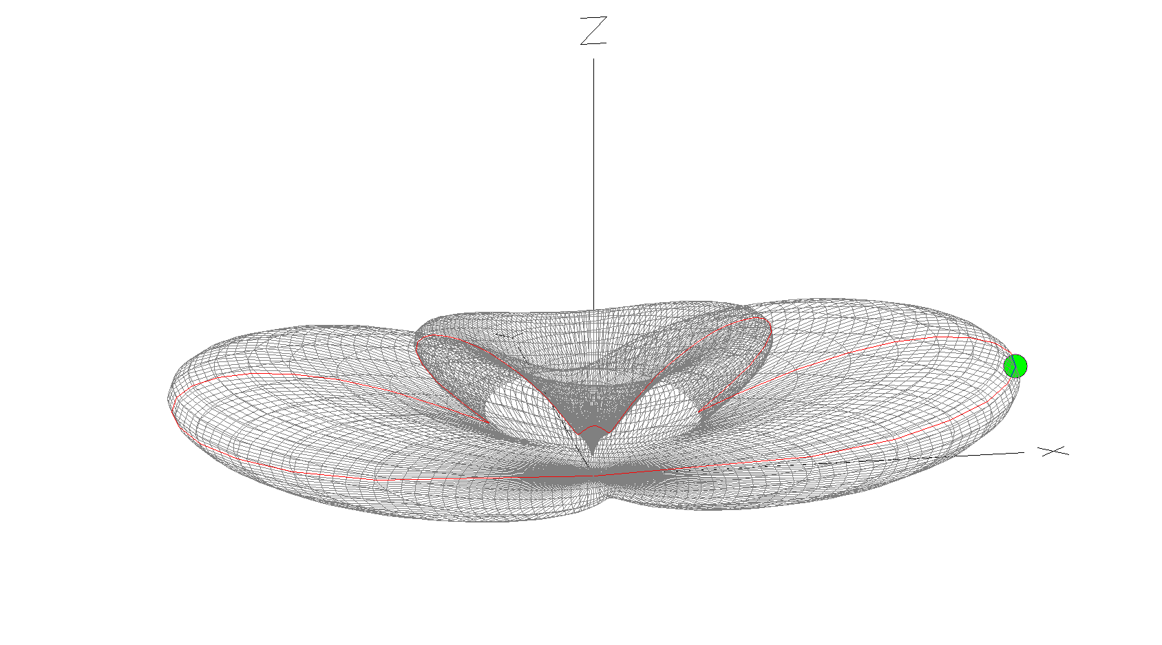
The 10m Band 3D Far Field Plot above shows the typical radiation pattern for the antenna. Maximum radiation is through the loop with very little high angle radiation making it ideal for chasing DX stations. Gain increases as frequency increases however, angle of maximum radiation decreases as frequency increases improving DX capability of the antenna on the higher bands. It’s worth ensuring that the antenna is rotatable as this will then enable you to point the antenna at the DX station to maximise signal strength at the DX end. Pointing this antenna North/South makes it great for working VK/ZL over the North Pole whilst at the same time being able to work South Africa from the UK.
Summary:
Horizontal Wire Lengths: 3m @ 20mm Diameter
Vertical Wire Lengths: 9.2m @ 2.5mm Diameter
Modelled Height above ground at Centre (Conductor 2): 10.6m
Feed Type: 4:1 Balun + ATU / Remote Auto ATU / 450 Ohm Ladder line with 4:1 Balun & ATU