I’ve now completed the GQRX Receive and Icom IC-705 Transmit dashboard in Node Red. It was a fun project to put together and needed some javascript coding to get the functionality I wanted but, I got there in the end.
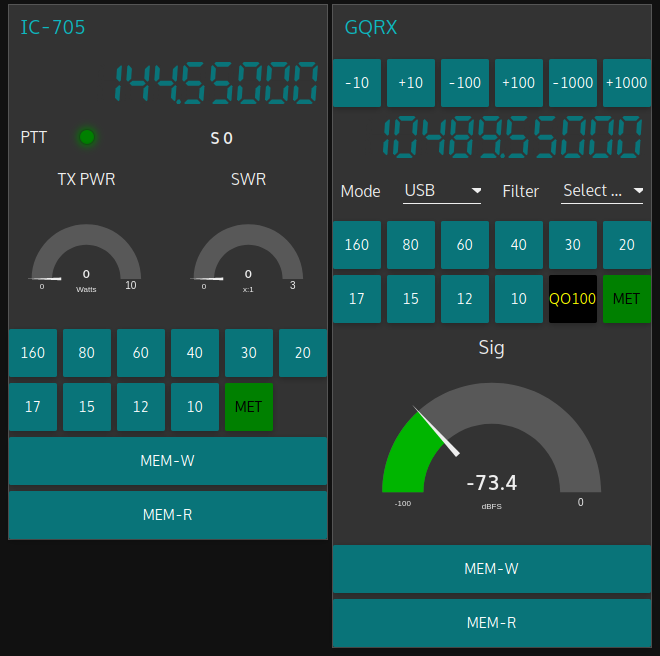
M0AWS QO-100 GQRX/IC-705 control dashboard
The dashboard looks fairly simple but, there is a lot behind the scenes to get it to this stage.
On the left is the Icom IC-705 transmit control panel. It shows the transmit frequency, power output and SWR reading. The SWR is so that I can check that the input into the 2.4Ghz transverter doesn’t have any connectivity issues. The “S0” will actually display the S Meter reading when the IC-705 is being used as a normal transceiver rather than being in QO-100 Duplex mode as shown above where the GQRX app and Funcube Dongle SDR are being used as the receiver.
The GQRX side of the dashboard shows the downlink frequency which tracks the uplink frequency of the VFO on the IC-705. This will ensure that the Funcube Dongle Pro+ SDR receiver will always be on the correct downlink frequency relative to the uplink frequency, thus I should always be able to hear my own signal coming from the QO-100 satellite.
Once taken out of QO-100 mode the two radios can be used independently on any of the HAM bands and can be switched using the buttons on the dashboard.
I also coded in a simple memory facility where a frequency can be stored in Node Red and recalled later on both the transmit and receive sides.
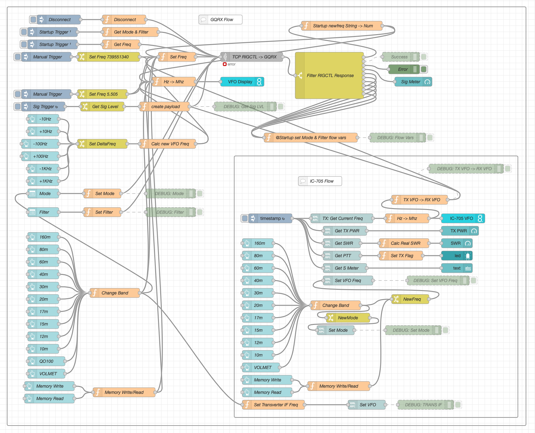
Looking at the dashboard it all looks simple and straight forward however, if you look at the Node Red flow it becomes obvious that this isn’t the case.
QO-100 Dashboard Flow in the Node Red Editor (Click for larger image)
There’s a lot to the flow to get the information from the receiver and transmitter so that it can be presented on the dashboard. There’s also some code to convert between Rigctl protocol used by the GQRX application and XMLRPC used by the IC-705 via FLRig and WFview. I had to also code around a bug in the Node Red XMLRPC node whereby you have to add 0.1 onto the VFO frequency for it to be passed onto the radio otherwise the information is never sent. This was a real pain of a bug to find but, with a little experimentation I found the problem and managed to code around it. The strange thing about this is that the 0.1 added onto the frequency isn’t actually passed onto the radio via the XMLRPC node, it just has to have that on input otherwise it doesn’t work at all. A very strange bug and hopefully one that will be fixed by the node developer in future releases.
All that is left to do now is add the temperature sensors dashboard to complete the dashboard. These haven’t arrived yet and so I’ve not been able to create the necessary flow to collect the data from them.
Hopefully this coming week the weather will improve and I’ll start getting the dish antenna up and the get the receive side working.
UPDATE: Further development of my QO-100 Dashboard has taken place, you can read all about it here.
Whilst I’ve been waiting for the weather to improve so that I can get my QO-100 dish antenna up I’ve been working on my QO-100 Node Red dashboard.
The idea of the dash board is to bring together the operating of the receiver and transmitter into one control centre so that the two separate devices are able to communicate and behave as if they were actually one device, like a transceiver rather than being individual components.
Ideally I would like to have the transmitter and receiver talking to each other such that when the VFO on the transmitter is incremented/decremented the receiver VFO also moves by the same amount.
By doing this the receiver VFO should always be in the right place on the 10Ghz band to hear my 2.4Ghz uplink signal and of course, any station coming back to my CQ calls.
So far I’ve only been working on the receive part of the Node Red flow, it’s certainly been a lot of fun getting it put together.
I control my Funcube Dongle Pro+ (FCD) using GQRX SDR on my Kubuntu PC. This software is working extremely well with the FCD and I’m happy with the level of functionality it offers.
GQRX SDR has the ability built in to control the SDR via remote TCP connection using RIGCTL protocol. Currently there isn’t a RIGCTL node available for Node Red so I have written a number of Javascript function nodes that provide the appropriate functionality in conjunction with a standard Node Red TCP node. This is working extremely well on the local LAN in the radio room and is proving to be very stable and responsive.
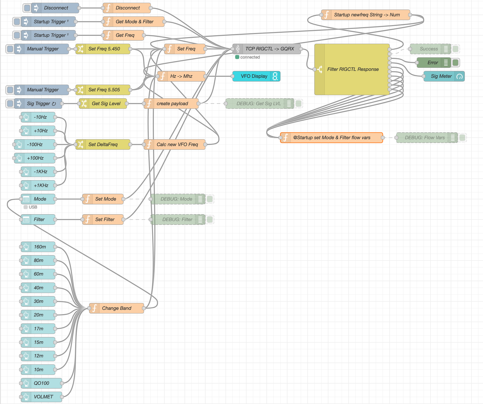
M0AWS QO-100 Node Red Flow – Receive Section
The flow for the receive section of the dashboard looks fairly complicated but, in reality it’s really not too difficult to get to grips with. The receive flow provides the facility to switch bands, switch modes, change receiver filter band width, display a realtime signal strength meter, receive +/- clarifier in 10/100/1000Hz increments and put the receiver into QO-100 mode where the SDR VFO is tuned to 739.550Mhz whilst the dashboard VFO shows the QO-100 downlink frequency in the 10Ghz band. This is all working very well and I’m happy with the initial result.
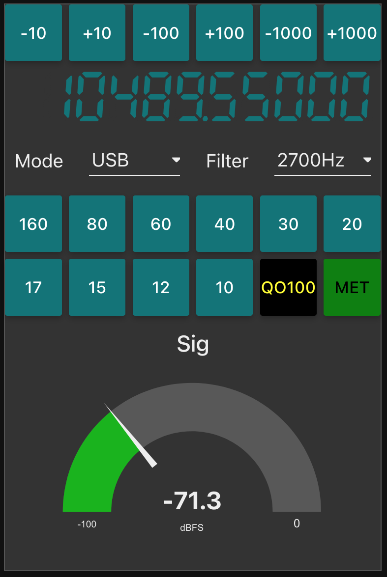
M0AWS QO-100 Receive Dashboard in QO-100 mode
I now need to start work on the transmit side of the QO-100 dashboard and get communications between my IC-705 transceiver and the FCD SDR working via Node Red. This could be a little more challenging as it will involve communicating with the IC-705 via WFView over wifi.
For a couple of weeks now I’ve been playing with Node Red to add functionality to my digital mode applications.
To get to know how it all works I initially used Node Red to create a series of dash boards for my servers and virtual machines to show realtime information on CPU temperature, CPU load, memory usage and storage etc.
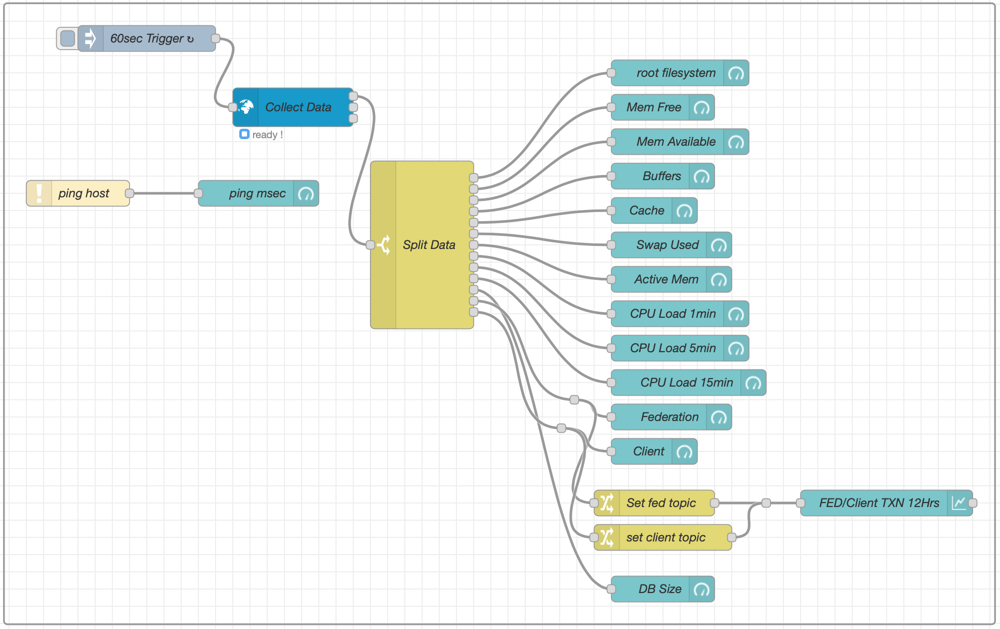
Node Red Flow to collect information from a virtual machine (VM)
This worked very well and I was soon able to generate the information I needed in a palatable format. This was a great way to get to know Node Red flow building and introduced me to using gauge and graph nodes in flows.
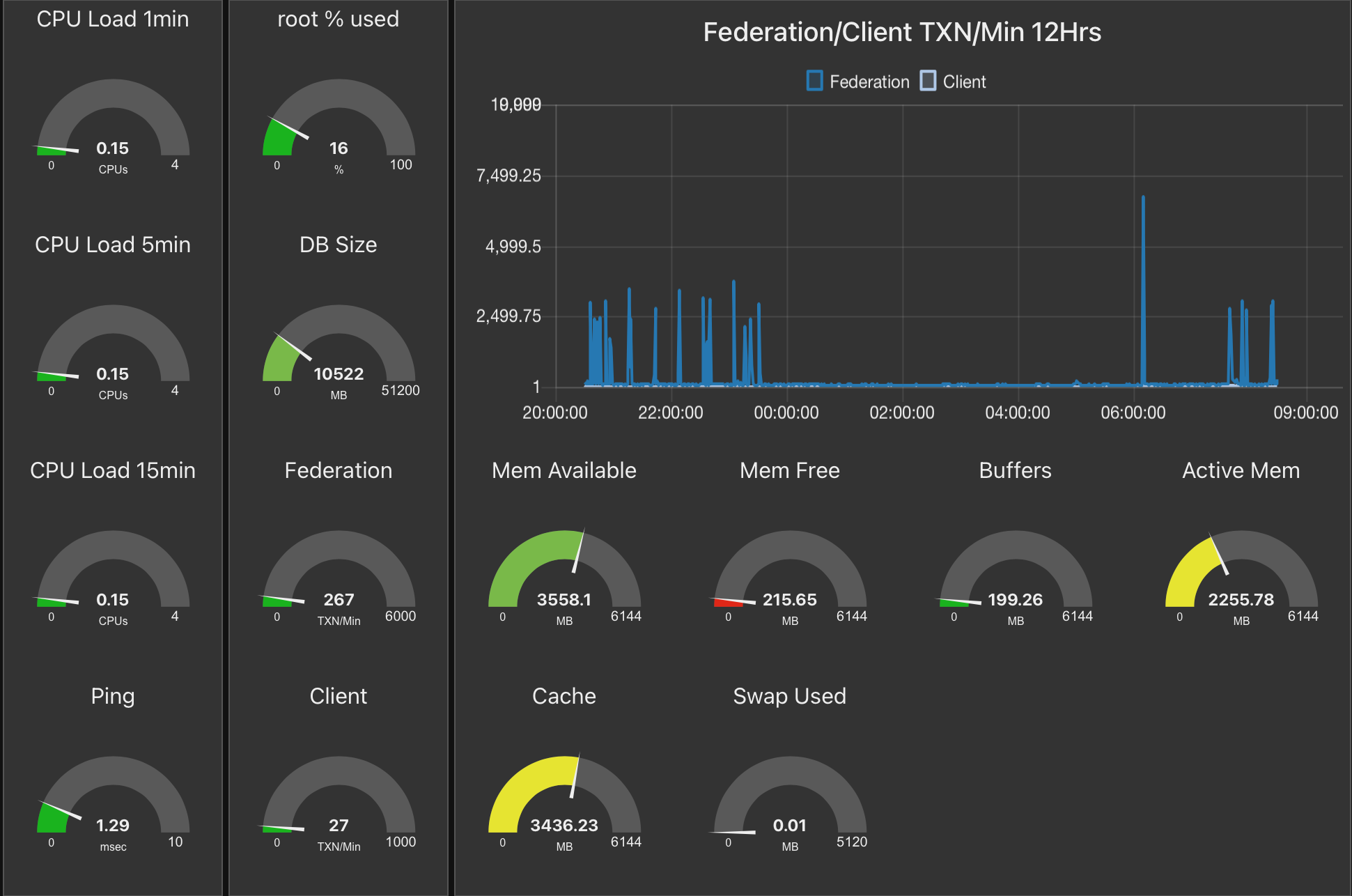
The resultant Node Red Dashboard for one of my Virtual Machines
Once I had mastered creating dashboards for servers/virtual machines (VMs) I then started to investigate using Node Red to plot data from WSJT-X on a map.
I currently use the PSKReporter website to see stations that I hear on a map as WSJT-X sends the data to the site automatically however, this information is always 5mins or more old. For some time I’ve been wanting to see the information realtime as it is received and so I was hoping to be able to achieve this via Node Red.
Node Red has nodes available for a multitude of applications all easily installed via the Manage Palette menu in the flow editor.
I installed the WSJT-X Decode and World-Map nodes and set about building a flow to capture the data and plot it on a world map.
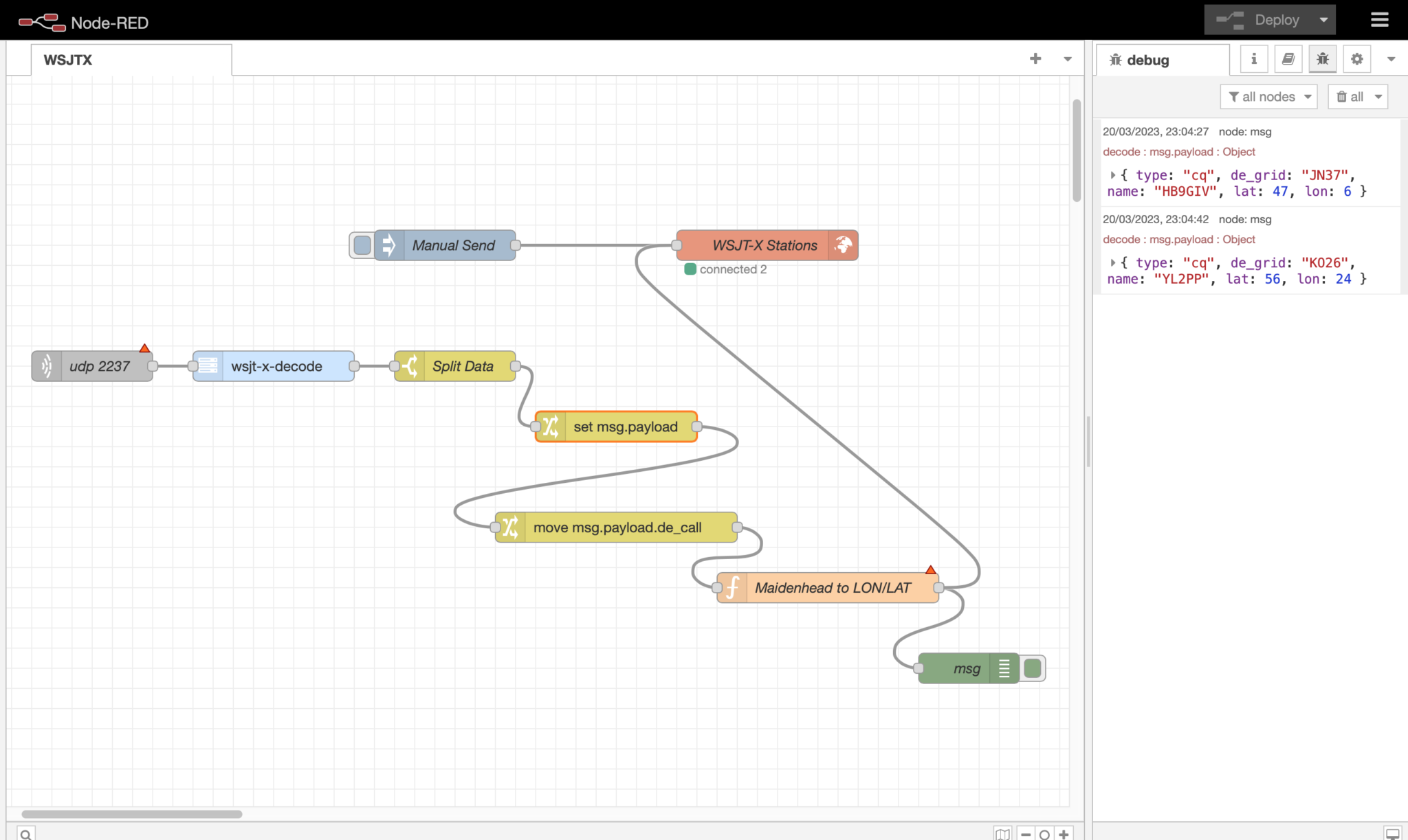
Building a Node Red Flow to decode WSJT-X data and plot it on a World Map
Putting the building blocks of the flow together is fairly straight forward and easily achieved using the excellent flow editor built into Node Red.
I configured WSJT-X to make the decode data available via UDP on port 2237 and then started the flow by creating a UDP node that connects to WSJT-X using the same port. The data immediately started flowing and I could see the information via a debug node.
I can’t stress enough how useful debug nodes are in Node Red. You can add debug nodes onto any output on any other node to capture the data as it flows. This gives you the ability to check what you’re getting is what you expected and also to see the format the data is in. The debug data is displayed in the debug panel on the right of the flow editor in realtime and gives you a great view of what is going on in your flow.
I decided to start with capturing the data for stations calling CQ as this was easily identifiable in the JSON object coming out from WSJT-X.
Passing the output from the WSJT-X-Decode node into a switch node I added a rule that filtered out data containing “type: “cq” and passed it onto the next switch node that created a payload consisting of the station callsign, maidenhead grid square and type so that it could be passed onto the next node for processing.
The next node in the flow is a function, this is where it gets a bit tricky. To be able to plot data on the map we need the Lat/Lon coordinates of the station making the CQ call. Since WSJT-X uses maidenhead locator data I needed to convert this to Lat/Lon coordinates before passing the data to the map node to be plotted.
Since Node Red is written in Java all the functions have to be written in javascript. The problem here is that I am not a javascript programmer and so this meant I’d need to learn yet another programming language. Unfortunately Node Red doesn’t allow functions to be written in C, Rust, Go or Python, all languages that I know well and after retiring from over 40 years in the UNIX/Linux/IT world my enthusiasm for learning yet another programming language has wained somewhat.
Being so close to having a working solution I pressed on and after much head scratching I finally put together some javascript that converts the maidenhead locator information in to good old fashioned Lat/Lon coordinates. I’m sure a seasoned Javascript developer wouldn’t be impressed with my code but, it works and does what I need and so I’m happy with it for the time being.
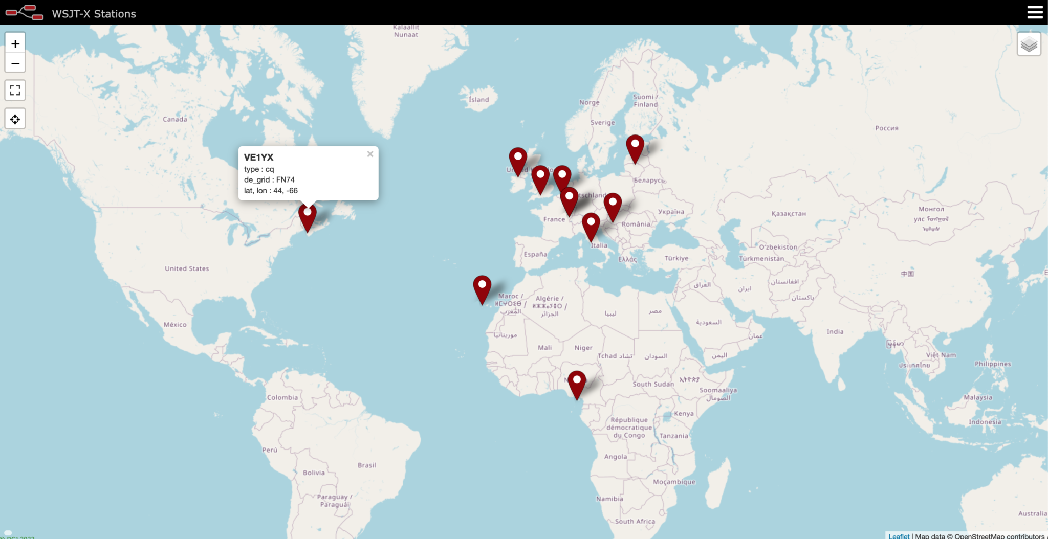
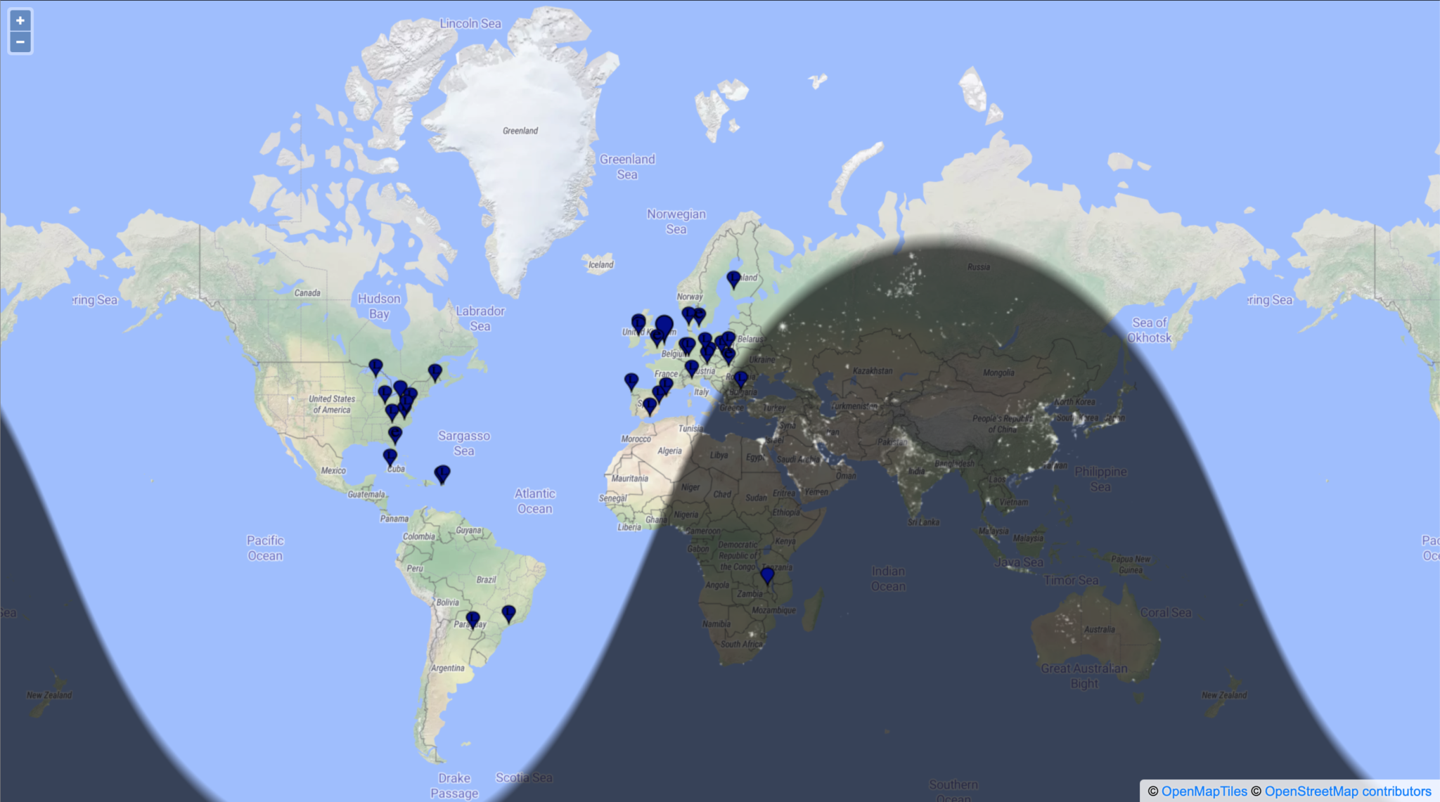
WSJT-X FT8 stations calling CQ on the 60m Band plotted on a Node Red World Map
Once I had the location information converted it was just a matter of passing the data to the world map node in the correct format for it to be plotted realtime.
As you can see on the screenshot of the map above, it worked extremely well with stations popping up as they were decoded by WSJT-X.
I now need to refine the data sent to the map so that it shows the frequency the station is calling on, the time they made the CQ call and the mode (FT8/FT4 etc) being used.. I would also like to add the distance from my QTH to the station calling CQ to round the information off however, this will mean writing another javascript function which, I’m not sure I want to dive into just yet.
I also need to add into the mix stations that aren’t calling CQ but, who’s callsign and grid square are passed on from WSJT-X. This will mean I will then be able to add to the map those stations that are actively working other stations and maybe I might even be able to show a line between the two stations that are in QSO.
This has been a fun but, steep learning curve however, it will certainly add some great functionality into my radio room and enhance my radio HAM addiction even further.
After much reading and viewing of youtube videos I have finally settled on the parts that I want to use to build my QO-100 Satellite ground station.
Initially I’m only going to build the receive path of the QO-100 station. From the articles and blogs I’ve read online all the experienced Amateur Radio satellite Op’s recommend getting the receive side sorted first and then moving onto the transmit path.
I need to stress here that I have no experience of radio above 433Mhz (70cm), a band that I have only used a handful of times. 99% of my Amateur Radio life has been spent below 30Mhz and so this is going to be a very new experience for me.
So, what am I going to purchase for the receive path?
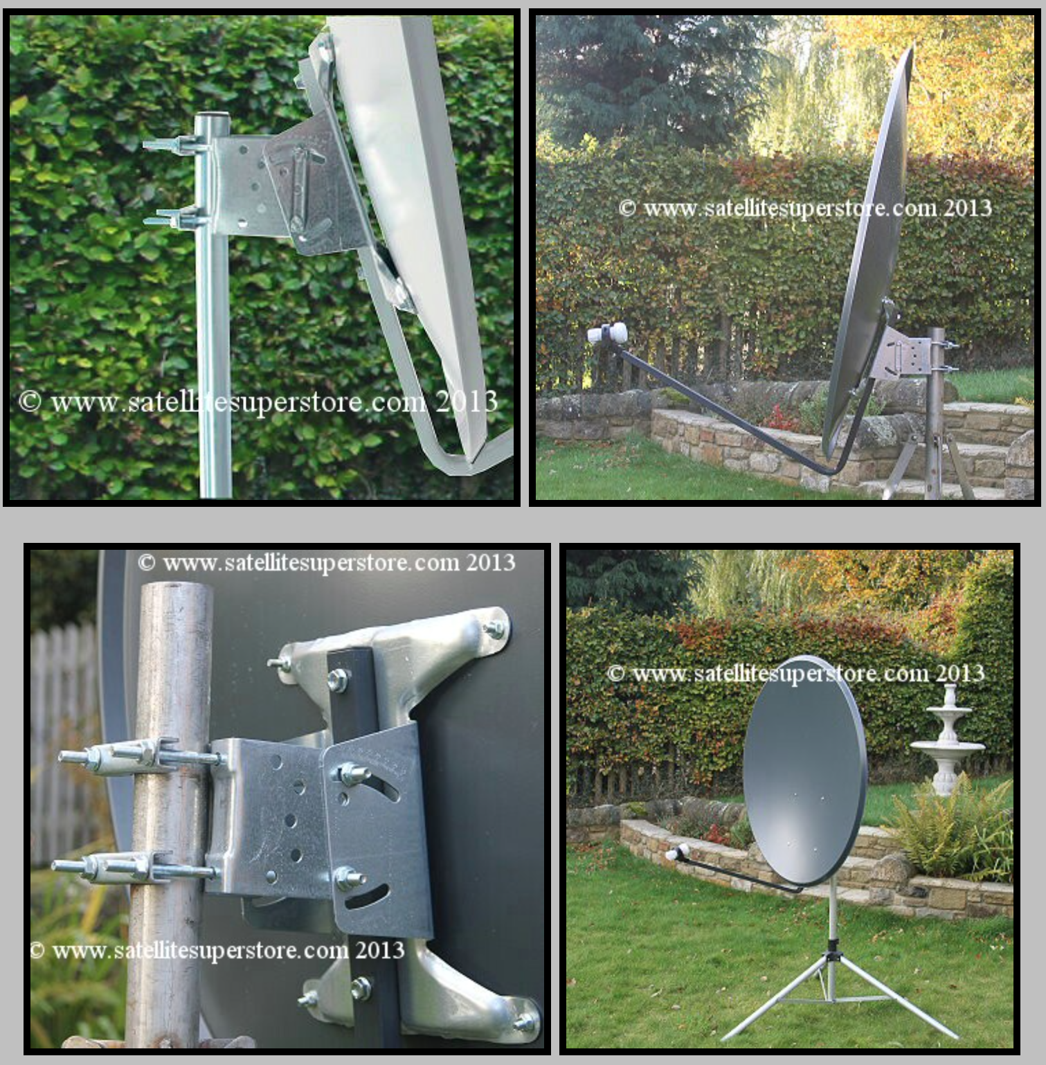
I’ve settled on a 1.1m off-set dish from the Satellite Super Store that should give me plenty of gain if I manage to get it pointed successfully at the bird.
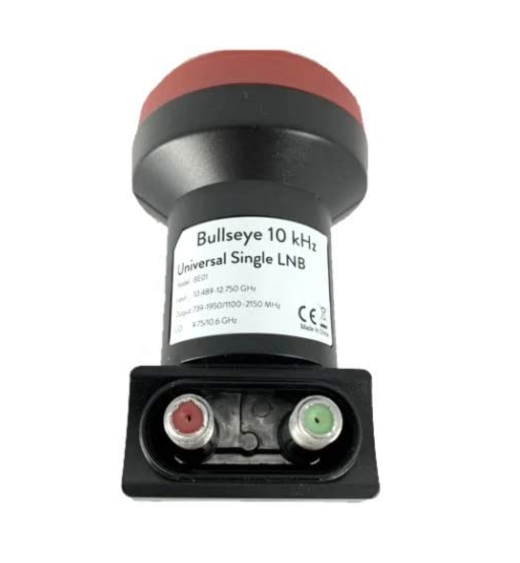
I’ll pair a Bullseye 10Ghz TCXO LNB with the dish to give me a high stability receive path that shouldn’t wander too much up and down the band with temperature changes throughout the seasons.
1.1m Off-Set Dish for QO-100
The Bullseye LNB gets extremely good reviews from the HAM Satellite community, although it is a little on the expensive side compared to many others available. Since I only want to do this once I’ve gone with the more expensive option in the hope that it gives me the stability I’m looking for.
Since we’ve never had satellite TV here at home I’ve only just learnt that LNBs require a voltage feed since reading about other peoples QO-100 station builds. Most LNBs can be used for either horizontal or vertical polarisation and are switched by feeding with either 12v or 18v respectively. The LNBs also use this same voltage feed to do the frequency down conversation and some amplification of the received signal.
At the moment I’m only looking to get onto the narrowband part of the QO-100 satellite service and so I will need to feed the LNB with around 12v to ensure vertical polarisation is achieved. The easiest way to do this is to inject the 12v feed up the coax cable to the LNB.
Bullseye 10Ghz TCXO LNB
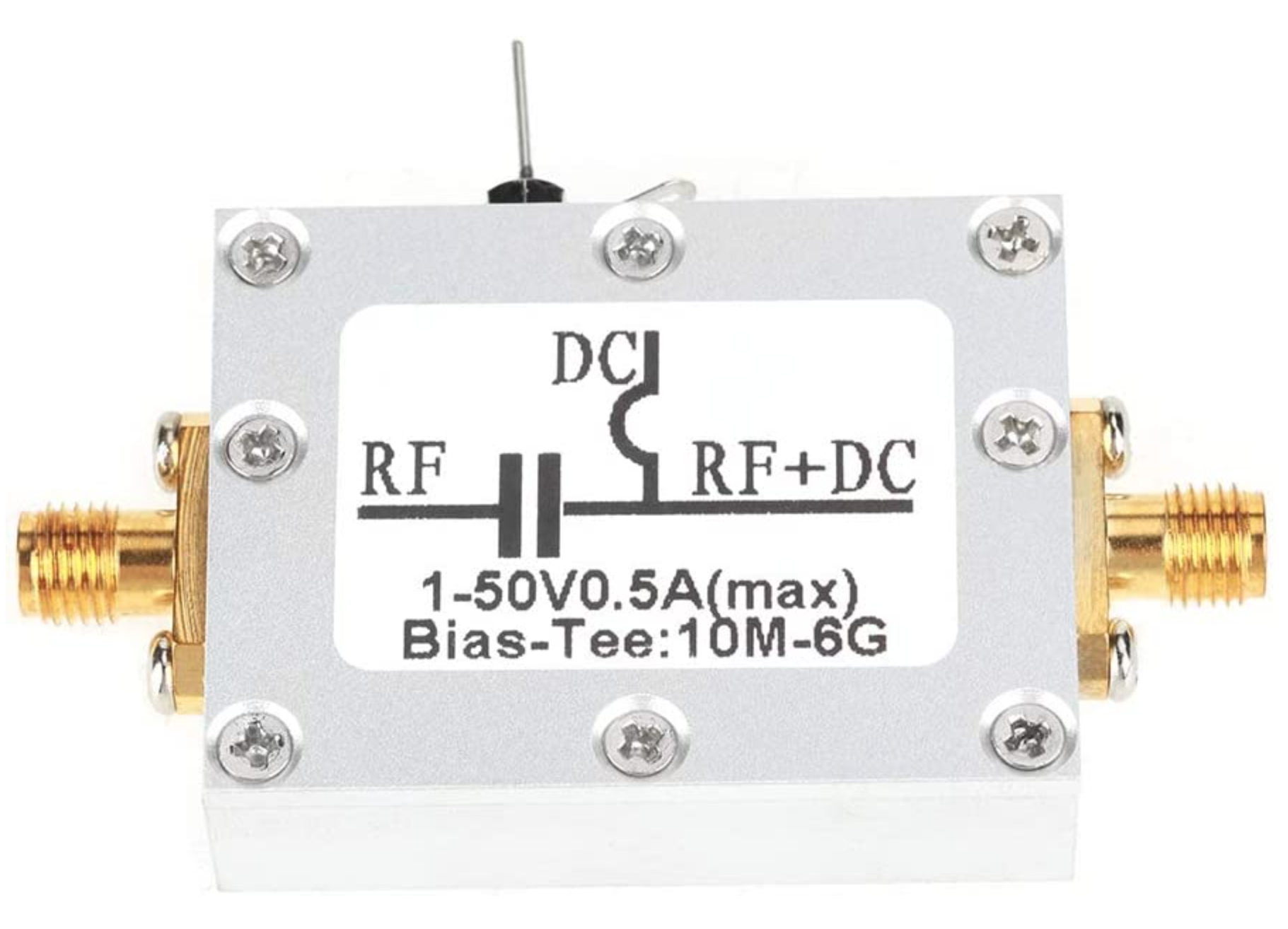
To achieve this I will need to purchase a little circuit called aBias Tee. This relatively simple circuit consists of a capacitor and inductor combination that stops the 12v from going back into the receiver whilst at the same time stopping the RF from going back into the power supply.
Bias Tee units are relatively cheap to buy online and I have decided to get one from Amazon that has been recommended in a number of blogs posts I have read during my research.
Broco Bias Tee
With these parts ordered I now need to source the materials to mount the dish up above head height in the garden with a clear view of the sky in the direction of the satellite.
Getting the dish up high enough to be above head height will be important for when I get the 2.4Ghz uplink path in place. At these frequencies it’s important to ensure that no one is able to walk across the front of the dish whilst I’m transmitting. I’m hoping to get the dish up about 3m in the air in such a fashion that it is rigid enough to stop the dish moving around in the wind. I must admit I’ve not done any wind load calculations for the 1.1m dish so I’ll have to see how it goes over time. Fortunately where I want to put the dish is fairly well sheltered from the north wind that often howls through here so, hopefully it won’t be an issue.
Having just completed building my new radio shack I thought what better way to break it in than to do an all night radio session chasing the DX.
All nighters aren’t anything new for me, I did many an all night session low band DXing when we lived in France (F5VKM). Back then I had a massive cellar, part of which was a very well fitted out radio shack. With some very large antennas in our field out back I was truly spoilt with some great times on the 160m band in the dark winter months.
Now back in the UK and only just getting back into the hobby after a long break things are somewhat different. I now only have a typical small UK garden and only vertical antennas. Better than no antennas though!
The new radio shack is small compared to my super spacious setup in France but, it’s perfectly formed with all facilities.
For my over night radio session I decided to use my trusty Yaesu FTDX10, it has the best receiver I’ve ever used and is built to withstand the long haul operation.
Antenna wise I decided to use my 30m band EFHW vertical that can be tuned on most bands from 80m and upwards. I use a CG3000 remote auto tuner to match this antenna to the 50 ohm coax feed and it does a great job.
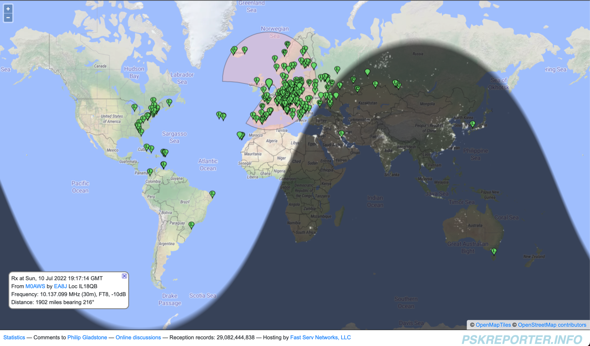
Being comfortably setup in the shack I tuned up on the 30m band and had a listen to see what shape the band was in.
Stations heard on 30m 10/11-07-22
Using FT8 I worked a bunch of European, Russian/Asiatic Russian stations with ease, the band was in fairly good shape albeit localised around Europe and Russia. Wanting to work stations a little further afield I decided to move up on to the higher bands. 12m is a band I really like but, always seem to miss when it’s open.
Tuning up on the 12m band using the same vertical that I was just using on the 30m band the FT8 section was packed with signals. At last, I’ve tuned up on the band when it’s open!
I suddenly noticed Bobby, VP8ADR down in the Falkland Islands in the WSJTX waterfall and gave him a call. He had a fair few people calling him and so I joined the list. In no time at all Bobby answered my call and we exchange SNR reports of -8dB both ways. This was surprising as later on one of the FT8 Facebook groups Bobby stated he was using 200w into a Hexbeam during our QSO, I was only using a measly 18w into my Vertical, I would had expected a much lower SNR report. Clearly Bobby’s setup was doing all the work!
Right after the QSO with Bobby I immediately went on to work PY7ZC, LU8YD, PY2ATI, LW6EQC, PY2EBD and PY2THO all in quick succession. With the Falklands, Brazil and Argentina in the log so soon it was looking like it was going to be a fun packed night.
Next up on the waterfall was 9Y4DG in Trinidad and Tobago and 8P6ET in Barbados, two really nice locations to get into the log and new ones on 12m for me.
Having worked all the DX I could hear on 12m and not wanting to just spend hours working endless European stations I tuned down onto the 17m band using the same vertical antenna. This antenna really does work well on bands it’s not designed for.
First 3 stations in the log on 17m were all from Japan, JR3NZC, JQ6RUP and JA5BDZ. With all 3 stations being well on the way to 6000 miles away this was a good start. The propagation strangely swung to the west and I got YV5DRN from Venezuela in the log.
Not seeing any other stations that I wanted to work I retuned back onto 30m again and found it was open to South America and the Caribbean.
In no time at all I had YV4CLF in Venezuela, HK2AQ in Colombia, NP4TX and NP3XF in Puerto Rico and PY7ZC in Brazil all in the log.
Being in complete darkness I decided to tune down on to the 60m band, one of my favourites, to see if there was much going on. Sure enough there were a few stations active on the limited space available.
First station worked was a new one for me FP/KV1J on St. Pierre and Miquelon Island just off the coast of New Foundland. I have to admit I had no idea where this little island was and confess to having to look it up on google maps.
I then went on to work a few East Coast USA stations all with good SNR reports for this time of year.
Stations heard on the 60m band 11-07-22
Having worked all the notable DX on 60m I tuned back onto the 17m which was now wide open to the world.
I stayed on this band for the rest of the night well into the morning grey line and beyond working some great DX including some new ones for me.
I worked many East Coast USA stations but, stations of note were 6Y5HN in Jamaica and AK6R, K6EU and K6EI in California on the West Coast USA. It’s rare for me to get into the West Coast USA for some reason.
UA0SDX in Irkutsk Siberia was also a nice one to get in the log. This is a town I was going to be riding my motorcycle through on my Mongolian trip before COVID19 and the war in Ukraine broke out and stopped the trip from happening. More information about my motorcycle adventures can be found on my Feralmoto website.
It was good to get an Ozzy call in the log too, VK6EI on the West Coast of Australia came in at a strong -15dB SNR giving me a surprising -14dB SNR report, incredible considering I was using just 22w into my vertical antenna.
Well after sunrise the DX was still pouring in and I worked KL7TC in Fairbanks Alaska, a new one for me that made me very happy as I’d been trying to get into Alaska for some time but, never seemed to time it right. Today was my day!
Another station I was really pleased to get into the log was V31MA. I’ve tried to get a QSO with this station many times but, have never succeeded until today. I called for about 20mins and eventually got a reply putting a huge smile on my face. -16dB SNR sent and -19dB SNR received, I was happy that I finally have Belize in the log.
The last station worked was RA0FF way over on the far East Coast of Russia, the complete opposite direction to Belize. Located in Yu-Sakhalinsk right on the Russian coast opposite Japan and at 5270 miles, this is my longest distance Russian station worked so far and one I was very happy to have in the log. I always get good take off towards Russia whether it be directly east or over the North Pole to the far eastern parts of the Siberian wilderness.
I had a great night chasing the DX on the HF bands and being retired didn’t have to worry about going to work after such a long night. I highly recommend that you try an all nighter at least once in your HAM radio career, you get the opportunity to work stations that you’d normally not hear during the day time hours.
You can see the full list of stations worked on the over nighter on my WSJTX Log page.
Since getting my Icom IC-705 I’ve had problems with computer noise causing interference when connected via USB. I solved the problem mostly by winding both the USB and coax cables around 240-31 ferrite toroids. This resolved the problem nicely on all HF bands except 10m. With further investigation I realised that the 240-31 ferrite toroid doesn’t provide much choking resistance at 28mhz and so a 240-43 would be better for the higher bands. This would mean I’d need a longer USB cable and coax to the AH-705 so that there was enough cable to wind around two ferrite toroids to cover all the HF bands.
Whilst this will almost certainly provide a complete solution to the problem there is of course another way around this issue. The IC-705 is a rare beast in that it has wifi capability built in. The wifi on the IC-705 is capable of operating in one of two different modes, Access Point (AP) and Station, a host on an existing wifi network.
Since I connected my IC-705 to my in-shack wifi I am using the radio in station mode for connectivity via wifi. By connecting it this way my MacBook Pro will also have access to the internet at the same time as connecting to the radio giving me the best of both worlds.
You can of course put the radio into AP mode and connect your computer directly to it via wifi however, you won’t have any internet access from the computer as it will be connected directly to the radio. This is how it will be used when in the field for portable operations unless you have a portable 3/4/5g wifi router.
Getting the radio connected to my shack wifi was easy, just go into the IC-705 menus, switch the WLAN on, pick the SSID of my wifi router and enter the password, the radio connects immediately. You will also need to switch on the network control option and also set up a user and password that is used when connecting to the radio from your computer. Refer to the IC-705 manual on how to do this if you haven’t done it already.
To be able to use the radio wirelessly from any Apple Mac computer you will need 2 applications, WFview and Blackhole. Both of these applications are Opensource Software, I’m a huge fan of Opensource Software and have over the years been involved in a number of opensource projects.
I’m fully aware that there is an application called SDR Control available on the Apple App Store for around £90.00 that can be used instead to connect to the IC-705 wirelessly however, I prefer to use Opensource software where possible.
Before proceeding with the instructions below make sure you have an up to date backup of your system. This installation and configuration shouldn’t cause any issues at all, it worked fine on my MacBook Pro but, it’s always best to backup before you install more complex software like this.
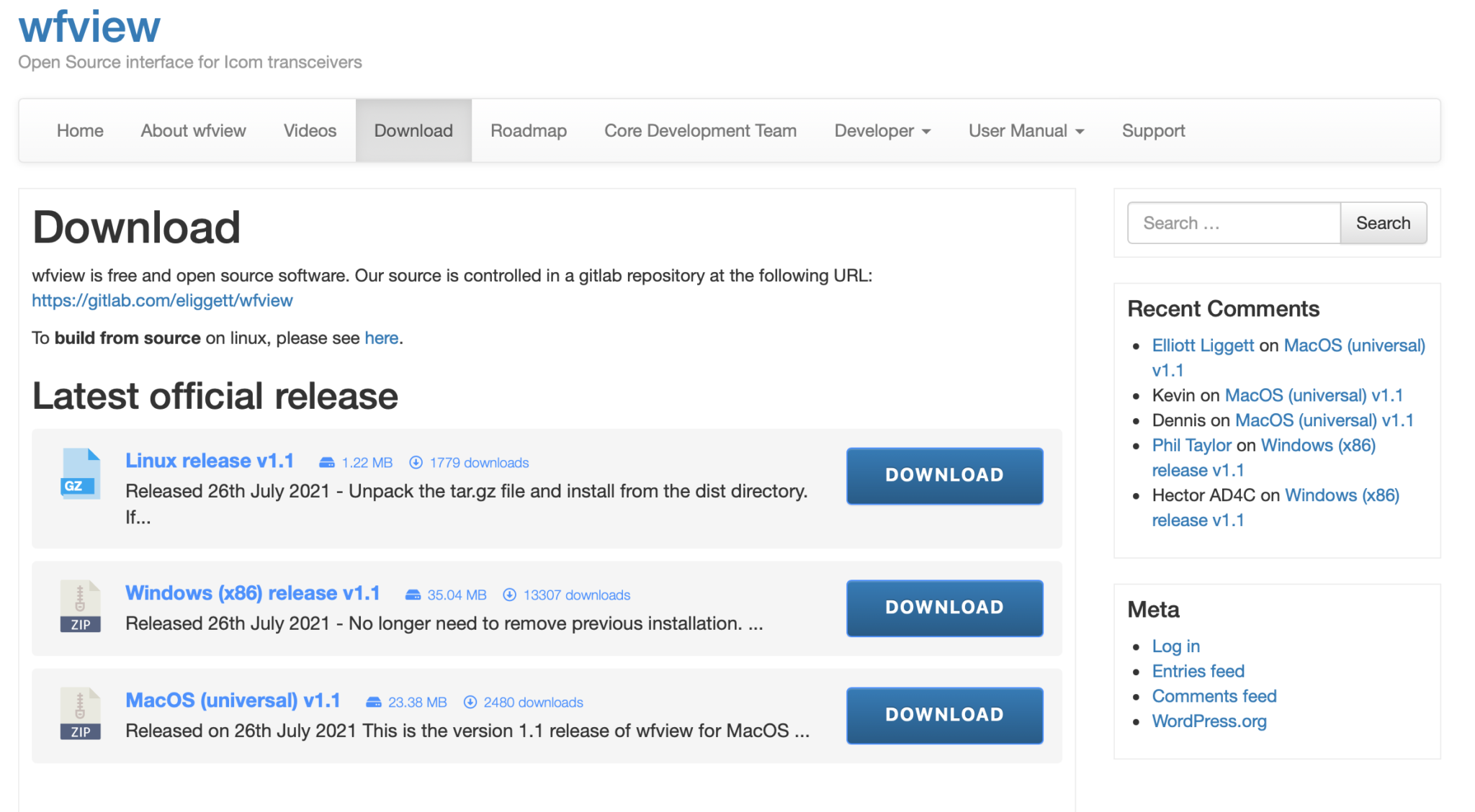
First you need to download WFView from the Download page, make sure to download the MacOS Universal package which was v1.1 at the time writing this article. Do **not** install WFView yet, the sequence of installation is important!
WFView Download page showing the MacOS (Universal) Package v1.1
Next download the Blackhole Virtual Audio Cable application from the download page. You will need to enter an email address and your name to be able to download the application. It’s not clear how much email/spam will be sent to you but, you will need to get at least one email to obtain the download link with the authorisation code in it.
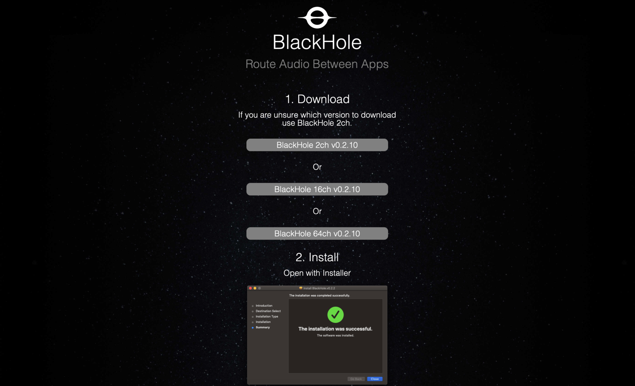
Once you’ve entered the information and submitted it you will get an email with a URL enclosed, click the URL and goto the download page. On the page there are 3 options available for download, select the “Blackhole 2 Ch” option only. At the time of writing this v0.2.10 was the current version available.
Blackhole Download page showing the 3 options available
Once downloaded you need to install the Blackhole application first as it will create the necessary virtual audio cable for WFView to use to provide sound to WSJT-X and other digital mode applications. Installation is simple and follows the normal MacOS installation process. Double click the installation package and follow the prompts accordingly.
Once installed reboot your Apple computer to make sure it starts up OK with the new kernel module installed. When your system comes back up, login and open the “Audio Midi Setup” application. (The Midi app is in Applications >> Utilities)
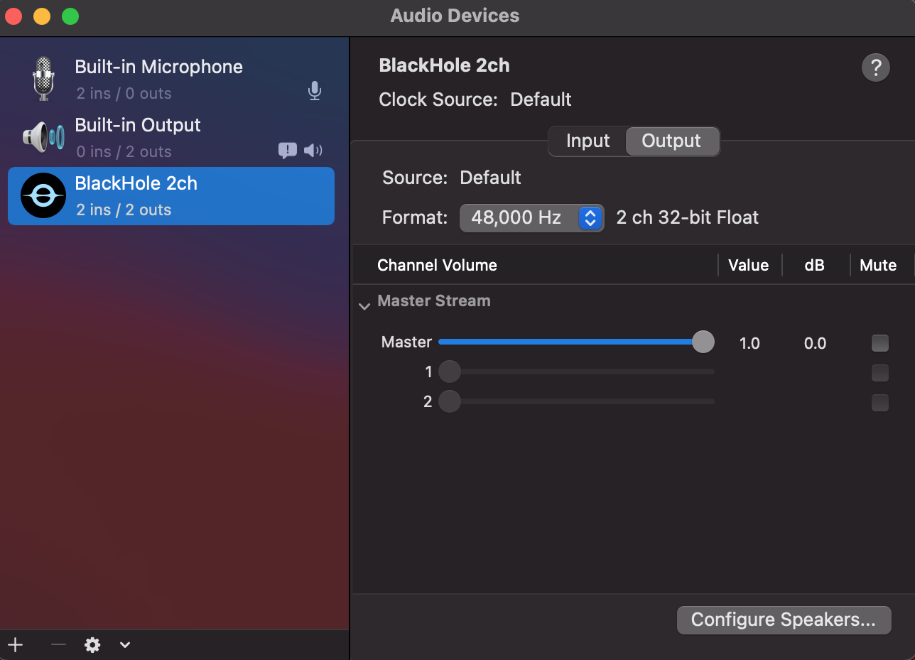
Once the application opens you should see that you have a new audio device called “Blackhole 2ch”. On both the Input and Output tabs set the format to 48,000Hz. This setting will get the best results when using applications like WSJT-X for FT4/8 digital modes.
Apple Audio Midi Setup showing 48,000Hz selected
Leave everything else as default setting in the Audio Midi App, nothing else needs changing. Leave the Master volume at the default max as levels are controlled from the other apps.
Once you’ve set the 48,000Hz on the two tabs quit the audio midi app as it’s no longer required.
Next you need to copy the WFView app that you downloaded into the Applications folder on your Mac. Once in the applications folder you can create a shortcut to it on the dock by dragging and dropping the app icon onto your dock bar.
Next goto your IC-705 and go into the WLAN settings and make a note of the IP Address assigned to the radio from your wifi router. You will need this IP Address later.
At this point you are half way to having wireless control of your IC-705.
Start the WFView application and goto the settings tab.
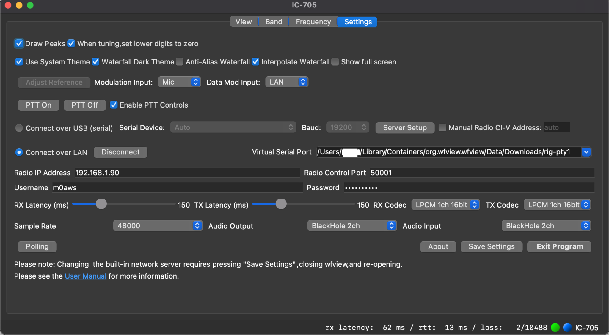
The following settings need to be made:
1: Set Data Mod Input to LAN
2: Click the Connect Over LAN radio button.
3:Enter the IP Address from your IC-705 into the Radio IP Address field.
4: Make sure Radio Control Port is set to 50001
5: Enter the Username you configured on your IC-705 into the Username field
6: Enter the Password you configured on your IC-705 into the Password Field
7: Set Sample Rate to 48000
8:Set Audio Output and Input fields to BlackHole 2ch
9: Select the first option available in the Virtual Serial Port field. This should be as shown below:
Leave all other settings as default and click Save Settings and then Exit Program.
You must exit the application in order to restart it with all the new settings.
WFView Settings tab showing all the necessary settings whilst connected to the radio
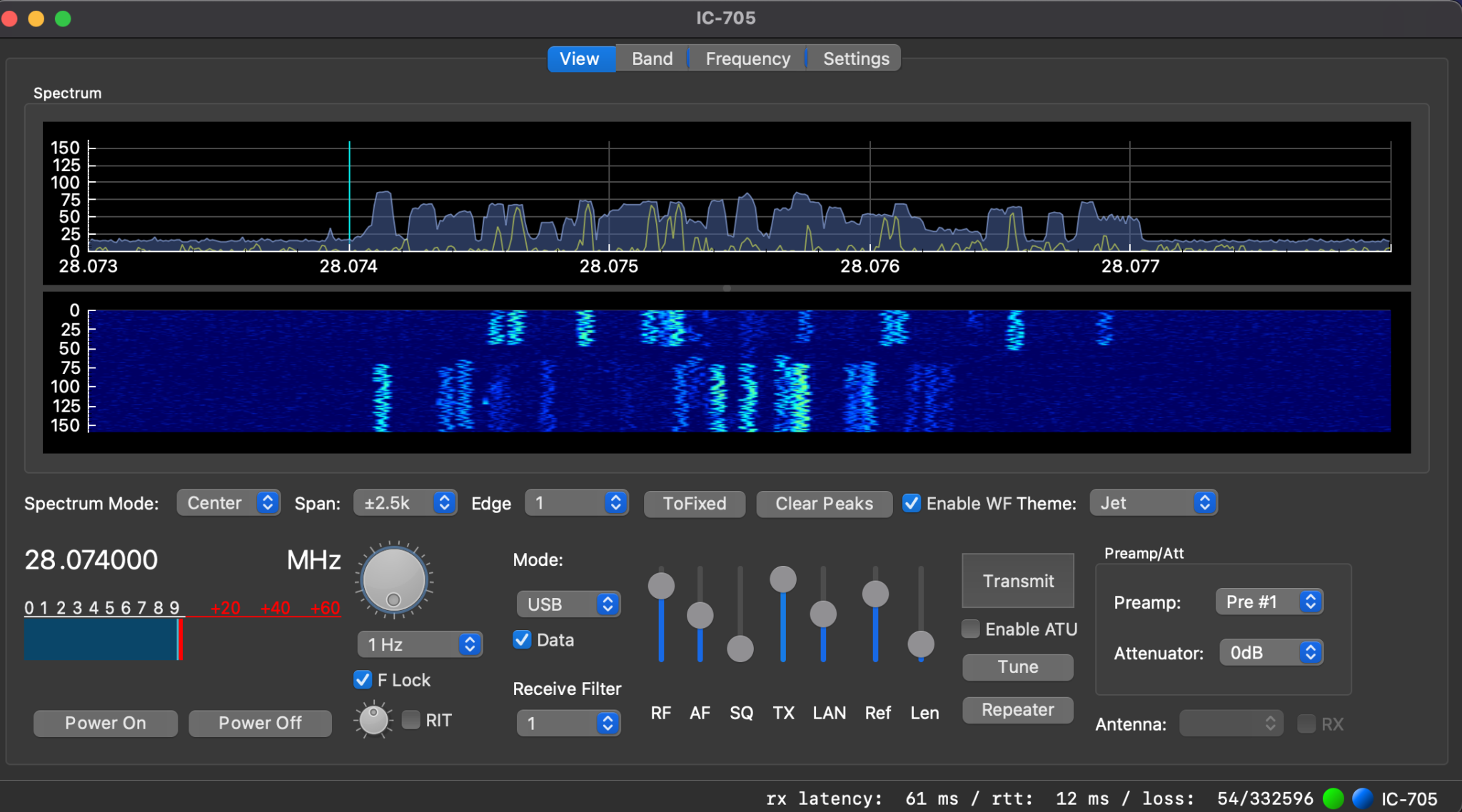
Start the WFView application again and goto the Settings tab. Click on the Connect Button.
Once it has connected to the radio you will see the RX Latency details etc on the bottom right of the window. Click on the View tab and you should now have an active waterfall.
At this point you have full control of your IC-705 wirelessly. Have a play with the application and get familiar with it.
Fully operational WFView connected to my IC-705 receiving FT8 on 10m
Once I had WFView operational I set about getting WSJT-X connected to the radio wirelessly. This is actually really simple to do and just needs a couple of changes to the settings to make it work.
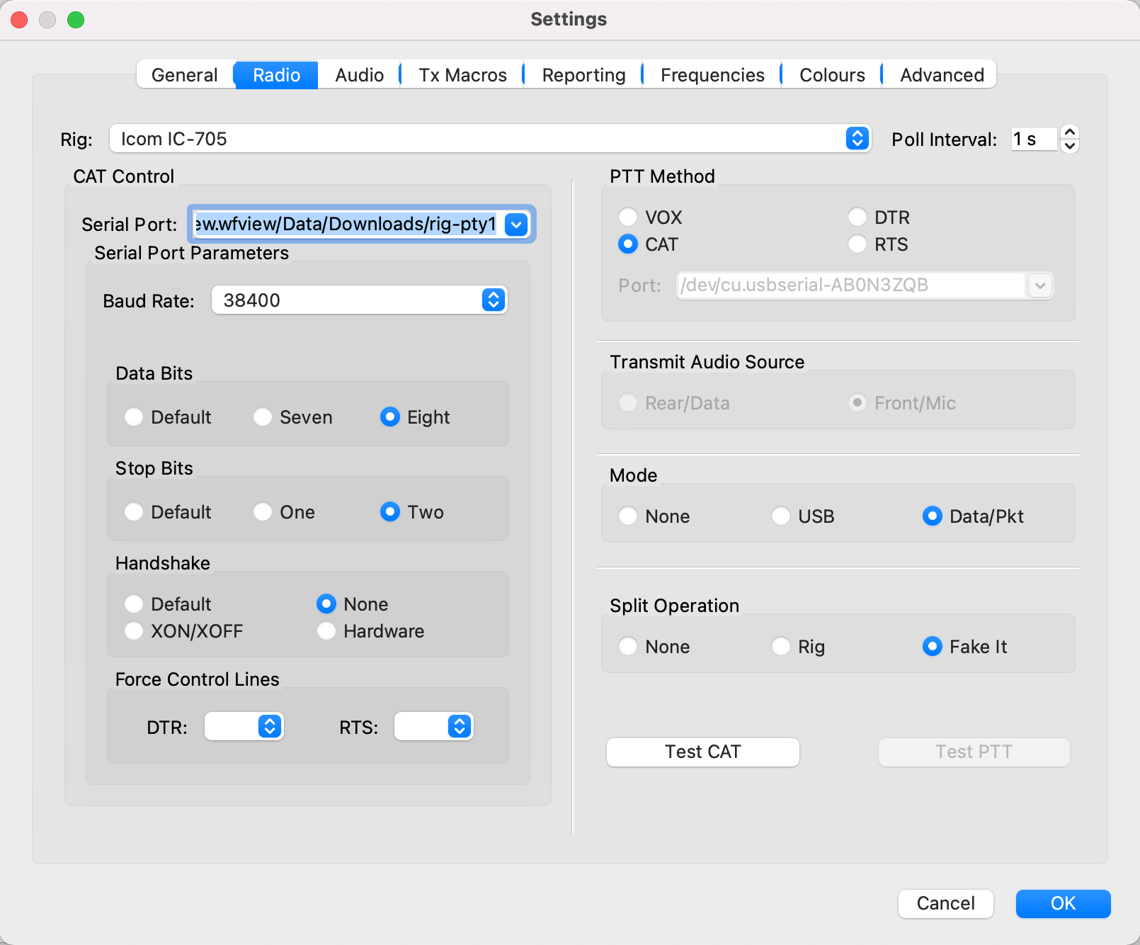
Start up the WSJT-X application and goto the Radio Settings tab. On this page you need to set the radio to IC-705, serial port to that shown below (Also shown in point 9 in the WFView section above) and Baud Rate to 38400.
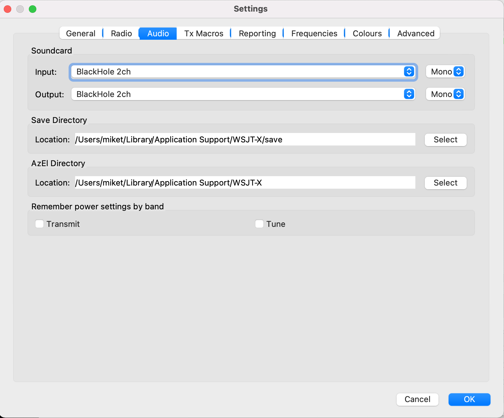
Next select the WSJT-X Audio Settings tab and set the soundcard Input/Output fields to Blackhole 2ch. Set both Input and Output to Mono as shown below.
WSJT-X Audio settings
Click OK and return to the WSJT-X main screen. You should now be fully operational for WSJT-X digital modes.
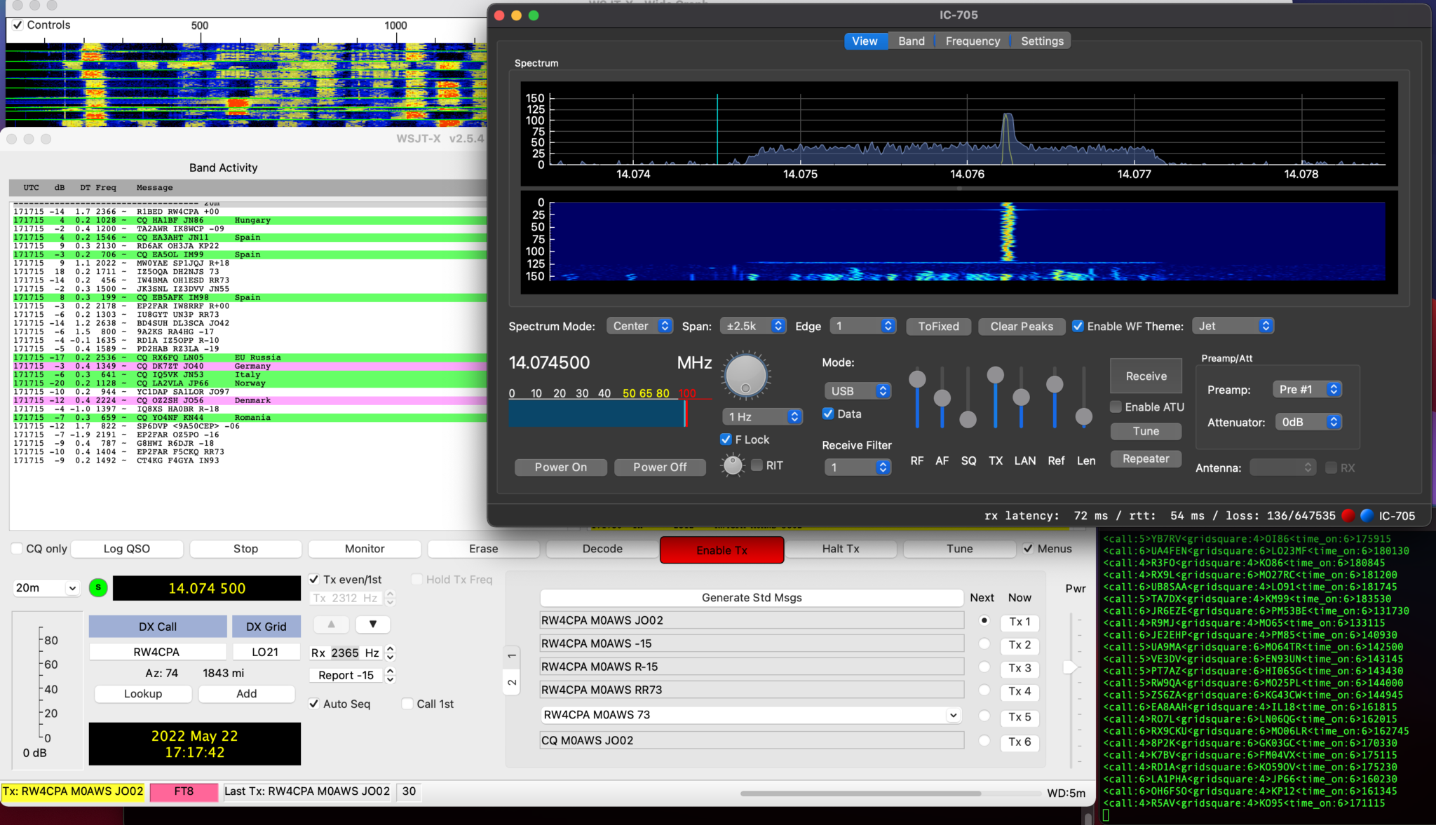
WSJT-X transmitting through WFView to the IC-705
Once I’d made a few contacts with WSJT-X in FT8 mode I went on to try and get FLDigi working with WFView as well.
Unfortunately at the moment I cannot get CAT control working in either FLDigi or FLRig, neither will accept the /dev/ttys000 as the serial device however, I was able to get the audio working into FLDigi and even decoded some morse with it. I need to do little more work to fathom out why the CAT control doesn’t work in these two applications. I’m sure there is a way to resolve this but, I just need to put in a little more time to find the solution.
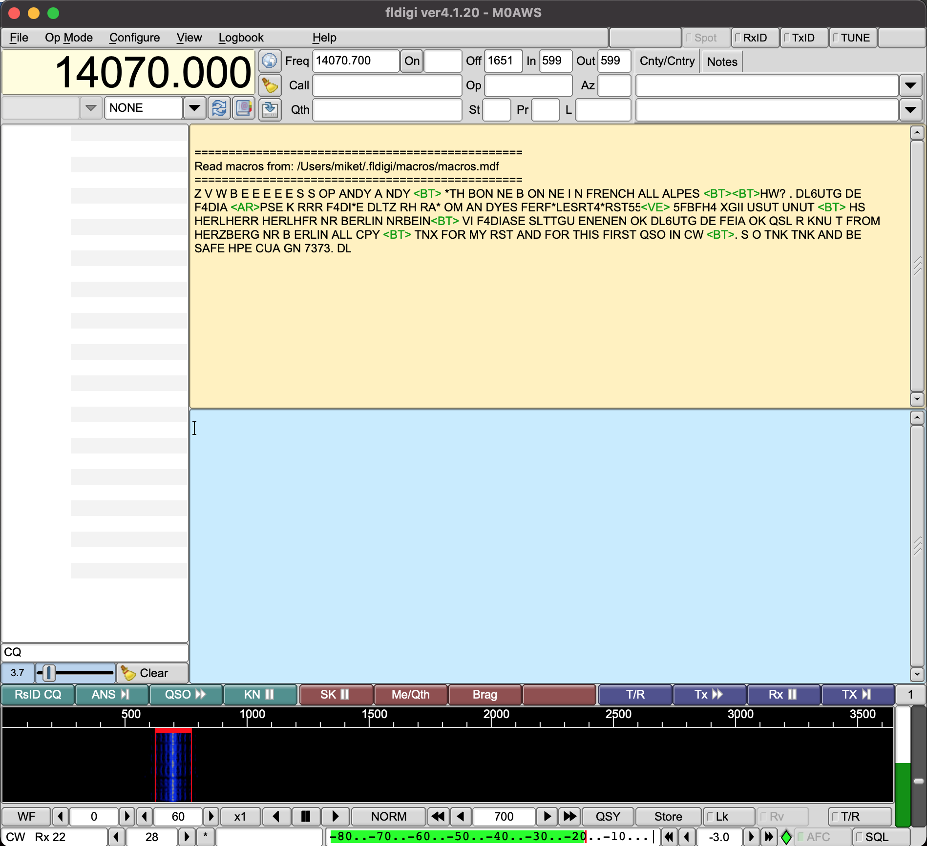
FLDigi decoding Morse code via WFView
UPDATE: There was some concern in one of the IC-705 Facebook groups that Blackhole wouldn’t work after a MacOS update. I’ve just upgraded my Macbook Pro to MacOS 11.6.6 and BlackHole is still fully functional afterwards. The MacOS update has no effect on the BlackHole service whatsoever. So you can rest easy!
More soon …
We use cookies to ensure that we give you the best experience on our website. If you continue to use this site we will assume that you are happy with it.Ok