QO-100 Satellite Ground Station Complete Build

I get quite a few emails from readers of my blog asking how my QO-100 satellite station is put together and so, I thought perhaps now is a good time to put together an article detailing the complete build.

My QO-100 satellite ground station is built around my little Icom IC-705 QRP transceiver, it’s a great little rig and is ideal for the purpose of driving a 2.4Ghz transverter/up-converter.

Of course all the software used for the project is Opensource and freely available on the internet.

M0AWS QO-100 Ground Station Build Visual
M0AWS QO-100 Ground Station Build Visual (Click to Enlarge)

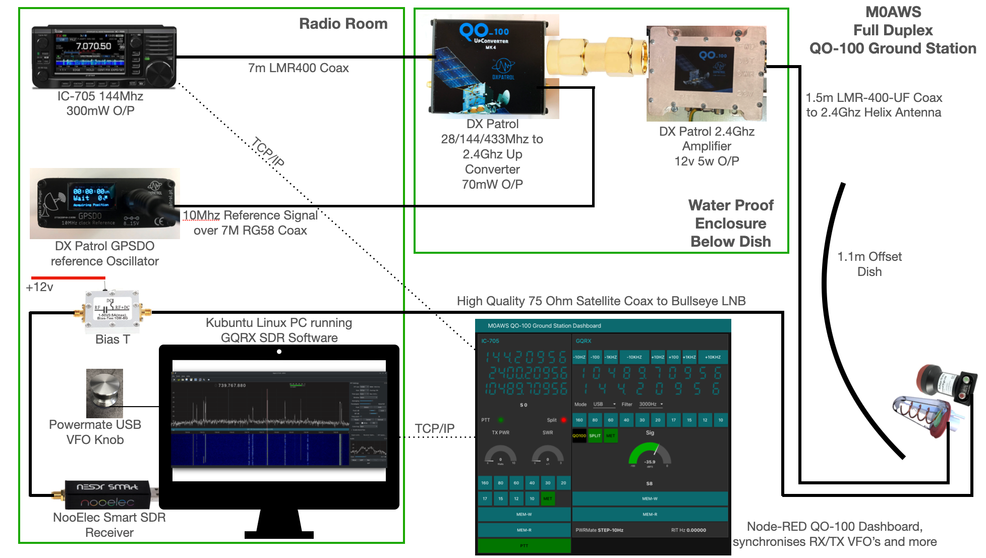
The station comprises of the following building blocks:

  • Icom IC-705 Transceiver
  • DXPatrol 28/144/433Mhz to 2.4Ghz Up-Converter
  • DXPatrol GPSDO Reference Oscillator
  • DXPatrol 2.4Ghz 5/12w Amplifier
  • Nolle Engineering 2.2 turn 2.4Ghz IceCone Helix Antenna
  • 1.1m (110cm) Off-set Dish
  • Bullseye 10Ghz LNB
  • Bias-T to feed 12v to LNB
  • NooElec SmartSDR Receiver
  • PC Running Kubuntu Linux Operating System
  • GQRX SDR Opensource Software
  • Griffin Powermate USB VFO Knob
  • QO-100 Ground Station Dashboard developed using Node-RED
  • LMR400-UF/RG58 Coax Cable
M0AWS QO-100 1.1m off-set Dish and IceCone Helix antenna ground station
M0AWS QO-100 1.1m (110cm) off-set Dish with IceCone Helix antenna and Bullseye LNB.

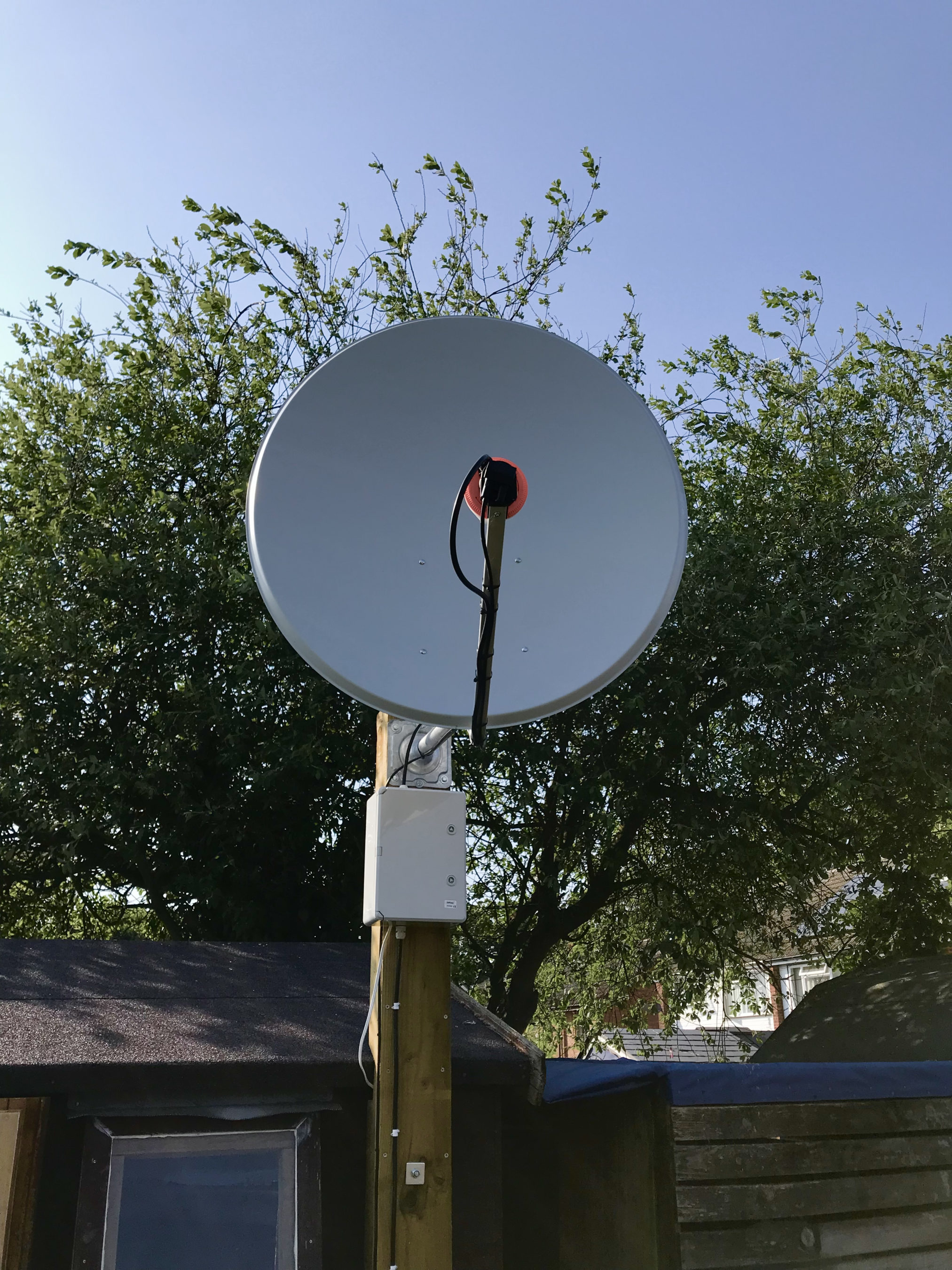
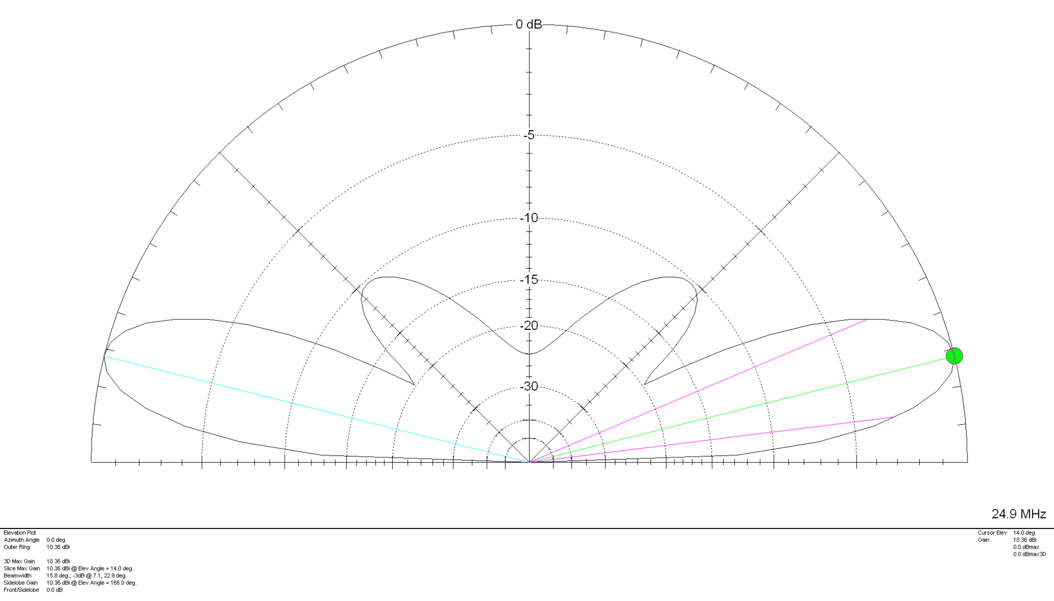
To get a good clear view of the QO-100 satellite I have the dish mount 3.2m above the ground. This keeps it well clear of anyone walking past in the garden and beams the signal up at an angle of 26.2 degrees keeping well clear of neighbouring gardens.

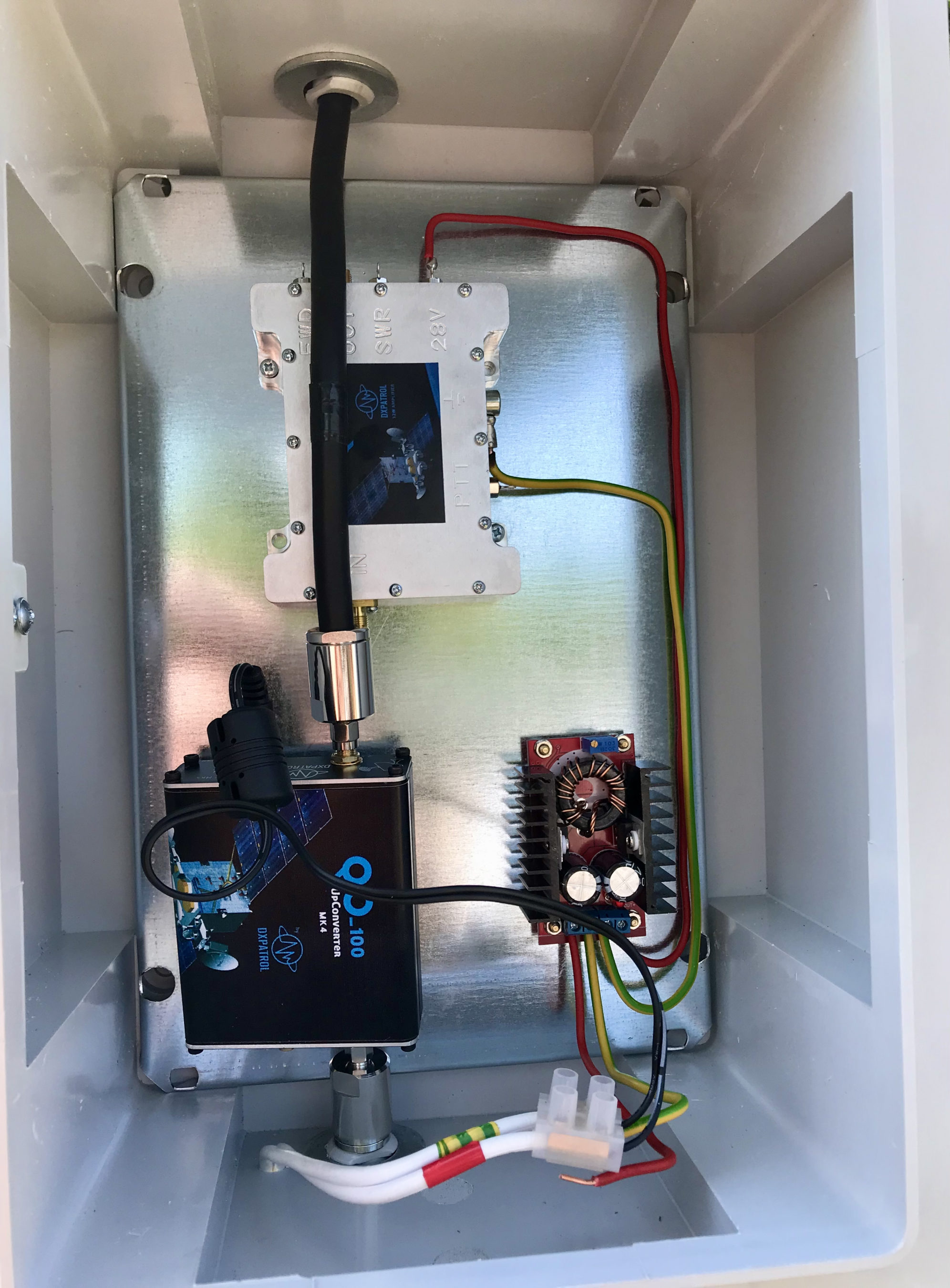
The waterproof enclosure below the dish houses all the 2.4Ghz equipment so that the distance between the feed point and the amplifier are kept to a minimum.

The DXPatrol amplifier is spec’d to run at 28v/12w or 12v/5w, I found that running it at 28v produced too much output for the satellite and would cause the LEILA alarm on the satellite to trip constantly. Running the amp at 12v with a maximum of 5w output (average 2.5-3.5w) is more than enough for me to have a 5/9+10 signal on the transponder.

The large 1.1m dish gives me quite an advantage on receive enabling me to hear the very weak stations with ease compared to other stations.

2.4Ghz ground station enclosure ready for testing

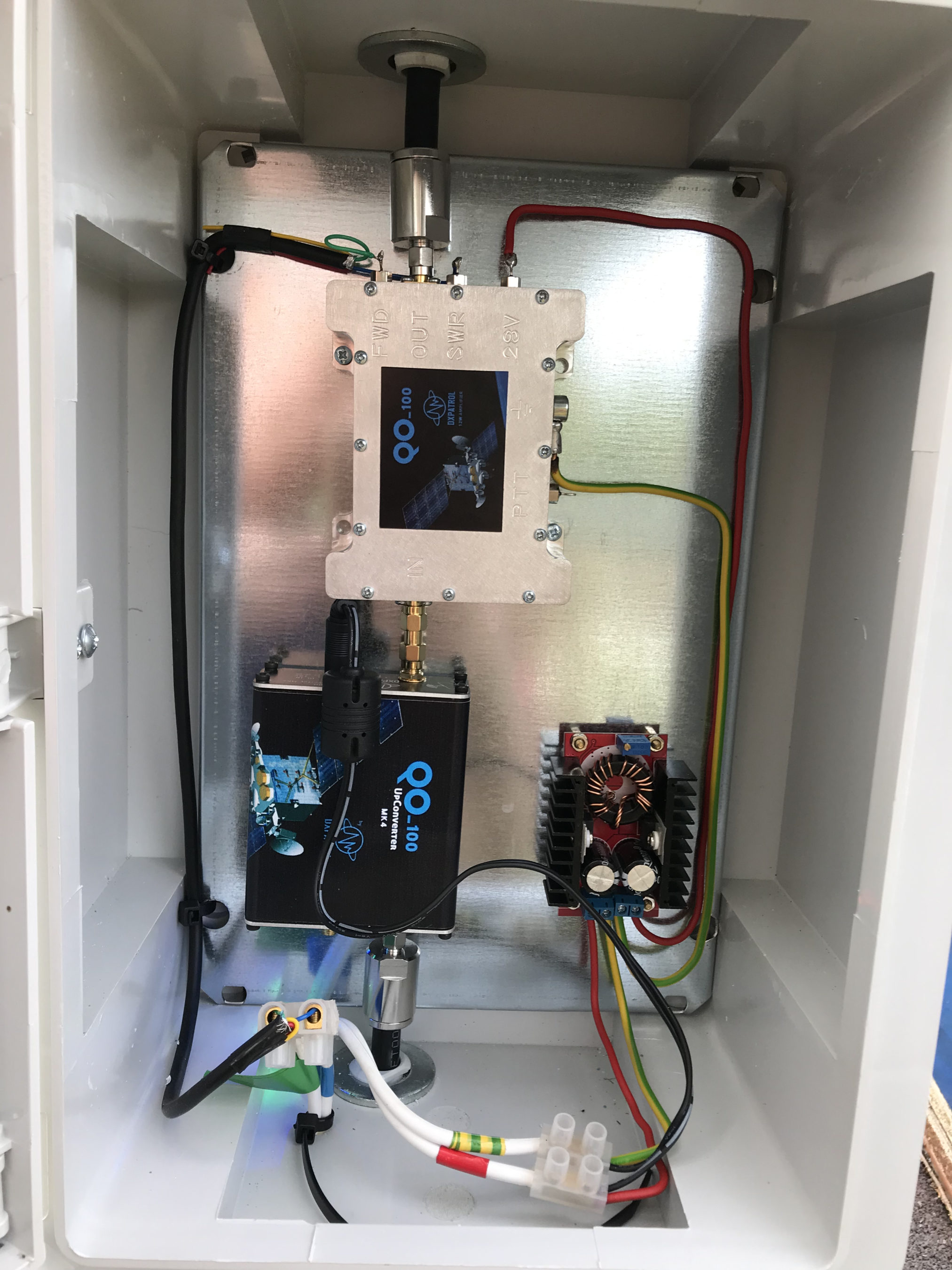
The photo above shows the 2.4Ghz equipment mounted in the waterproof enclosure below the dish. This photo was taken during the initial build phase before I rewired it so, the amplifier is shown connected to the 28v feed. To rewire the amp to 12v was just a matter of removing the 28v converter and connecting the amp directly to the 12v feed instead. This reduced the output from a maximum of 12w down to a maximum of 5w giving a much better (considerate) level on the satellite.

It’s important to keep all interconnects as short as possible as at 2.4Ghz it is very easy to build up a lot of loss between devices.

For the connection from the IC-705 to the 2.4Ghz Up-Converter I used a 7m run of
LMR-400 coax cable. The IC-705 is set to put out just 300mW on 144Mhz up to the 2.4Ghz converter and so it’s important to use a good quality coax cable.

Once again the output from the 2.4Ghz amplifier uses 1.5m of LMR-400-UF coax cable to feed up to the 2.2 turn Icecone Helix Antenna mounted on the dish. This keeps loss to a minimum and is well worth the investment.

Bullseye 10Khz High Stability Unversal Single LNB for 10.489-12.750Ghz

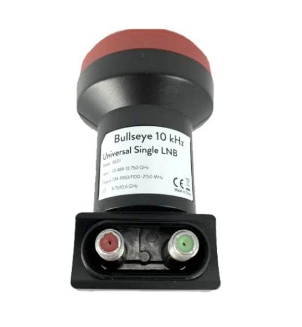
The receive path starts with a Bullseye LNB, this is a high gain LNB that is probably one of the best you could use for QO-100 operations. It’s fairly stable frequency wise but, does drift a little in the summer months with the high temperature changes but, overall it really is a very good LNB.

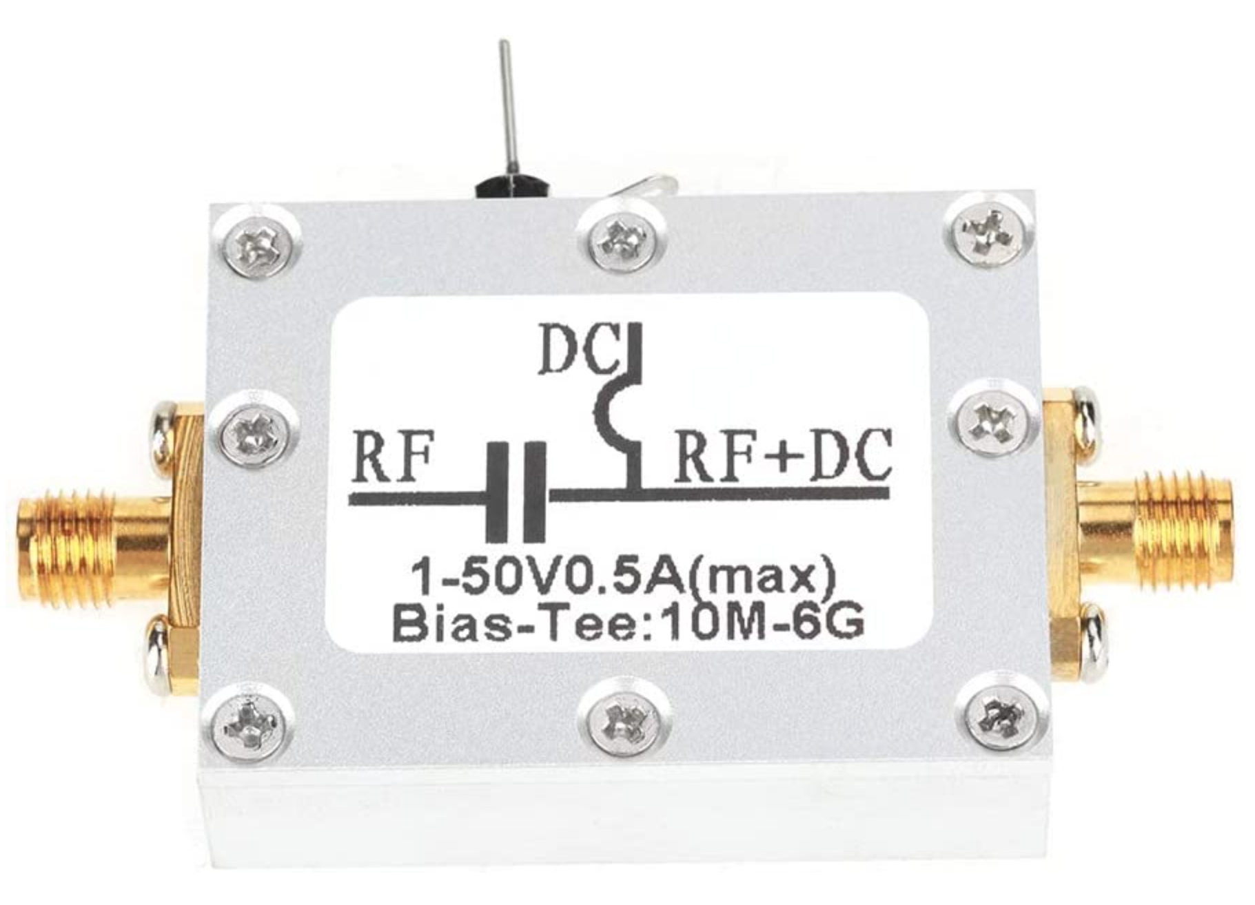
The 12v feed to the LNB is via the coax and is injected by the Bias-T device that is in the radio shack. This 12v feed powers the LNA and associated electronics in the LNB to provide a gain of 50-60dB.

Bias-T to inject 12v feed into the coax for the Bullseye LNB

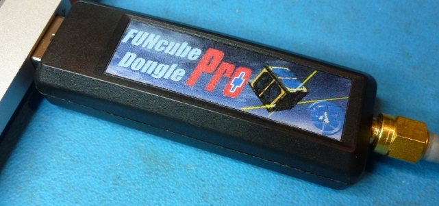
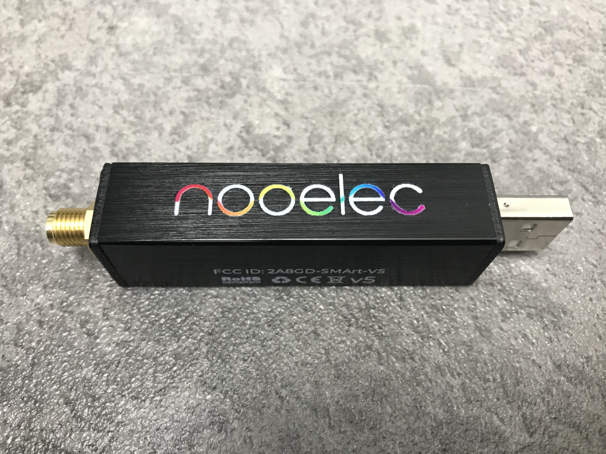
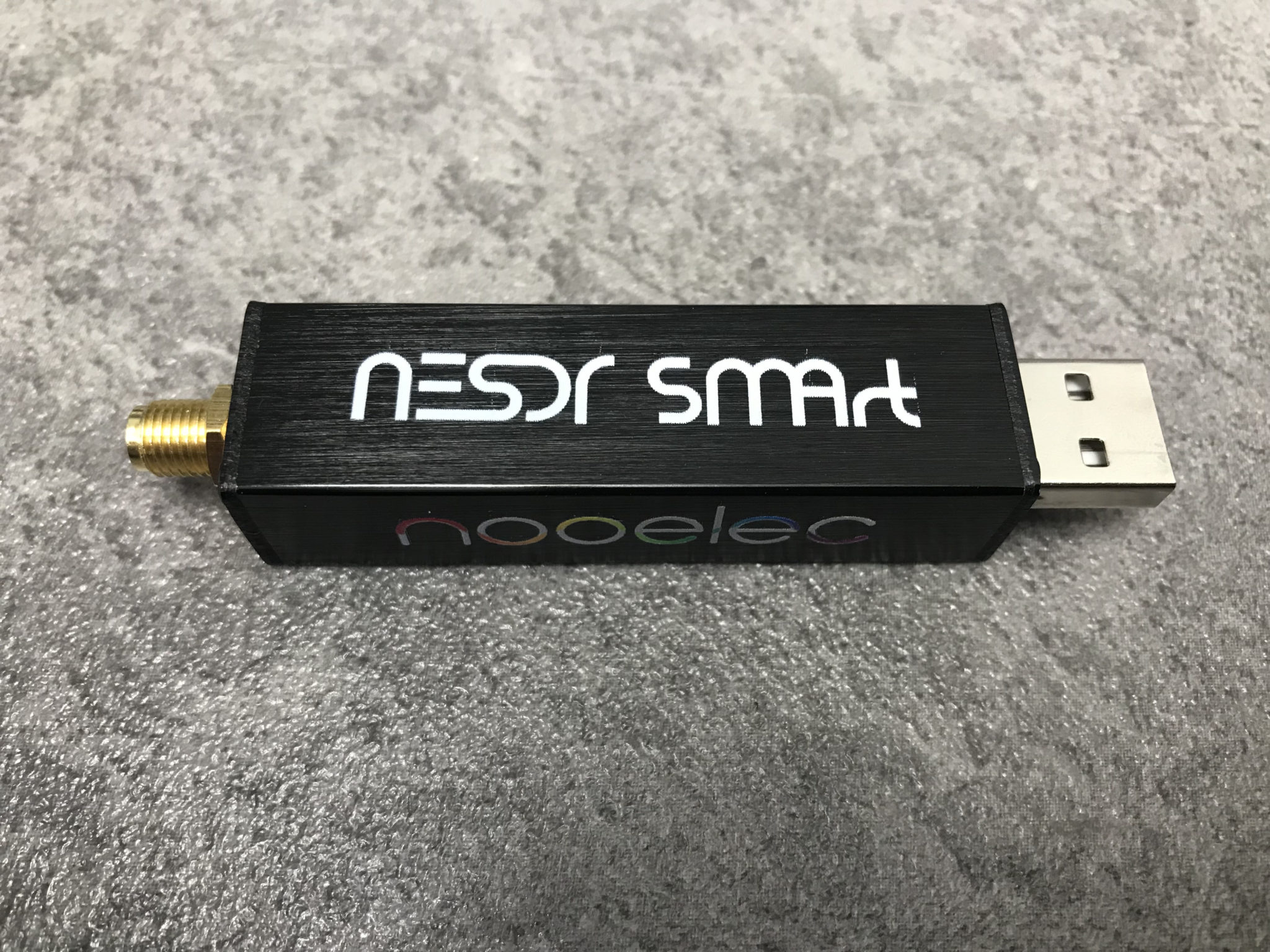
From the Bias-T the coax comes down to the NooElec SmartSDR receiver. This is a really cheap SDR device (<£35 on Amazon) based on the RTL-SDR device but, it works incredibly well. I originally used a Funcube Dongle Pro+ for the receive side however, it really didn’t handle large signals very well and there was a lot of signal ghosting so, I swapped it out for the NooElec SDR and haven’t looked back since.

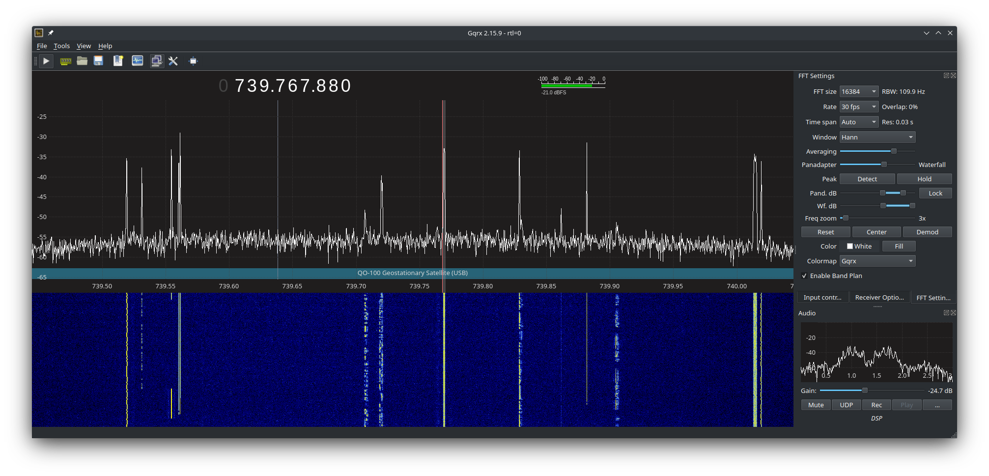
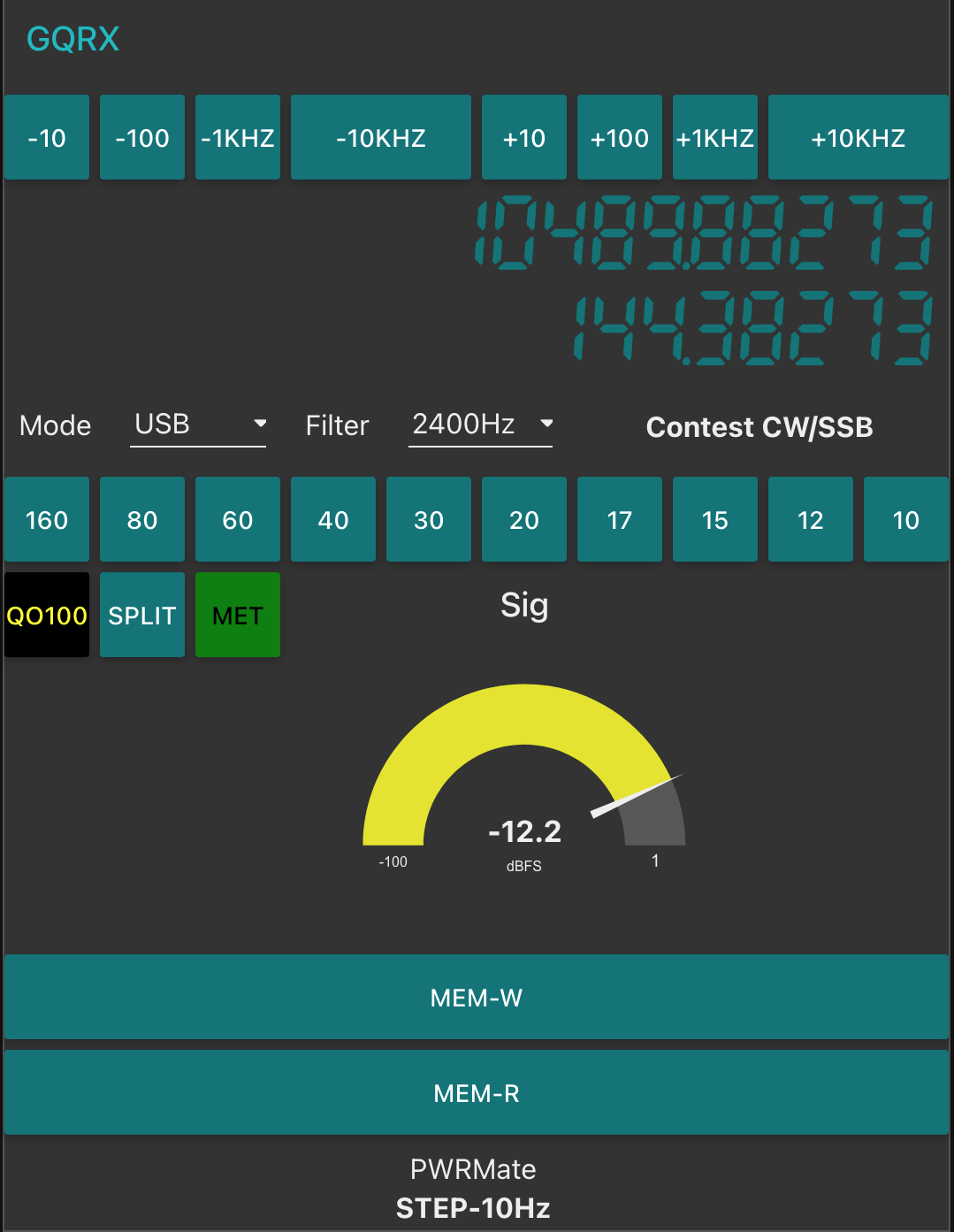
The NooElec SmartSDR is controlled via the excellent Opensource software GQRX SDR. I’ve been using GQRX SDR for some years now and it’s proven itself to be extremely stable and reliable with support for a good number of SDR devices.

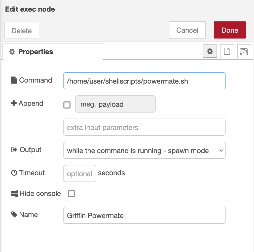
To enhance the operation of the SDR device I have added a Griffin Powermate VFO knob to the build. This is an old USB device that I originally purchased to control my Flex3000 transceiver but, since I sold that many moons ago I decided to use it as a VFO knob in my QO-100 ground station. Details on how I got it working with the station are detailed in this blog article.

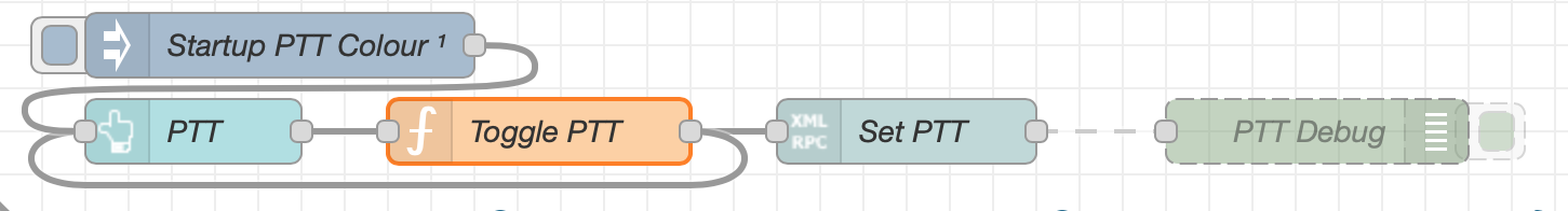
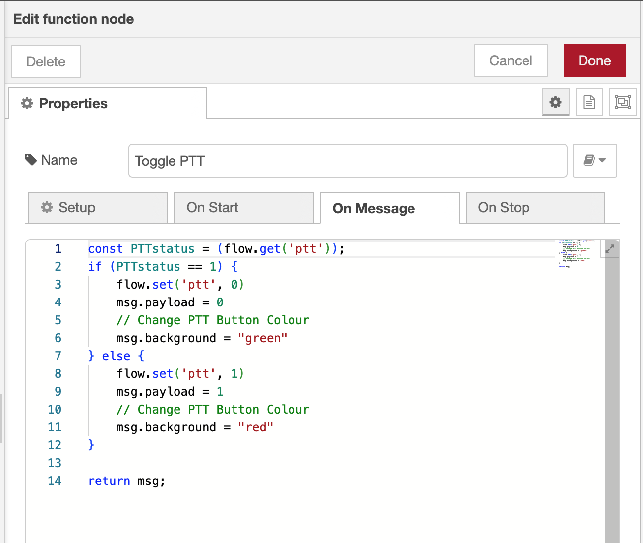
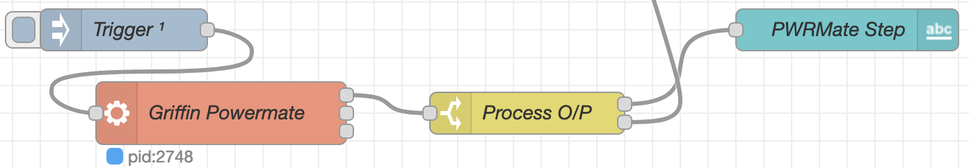
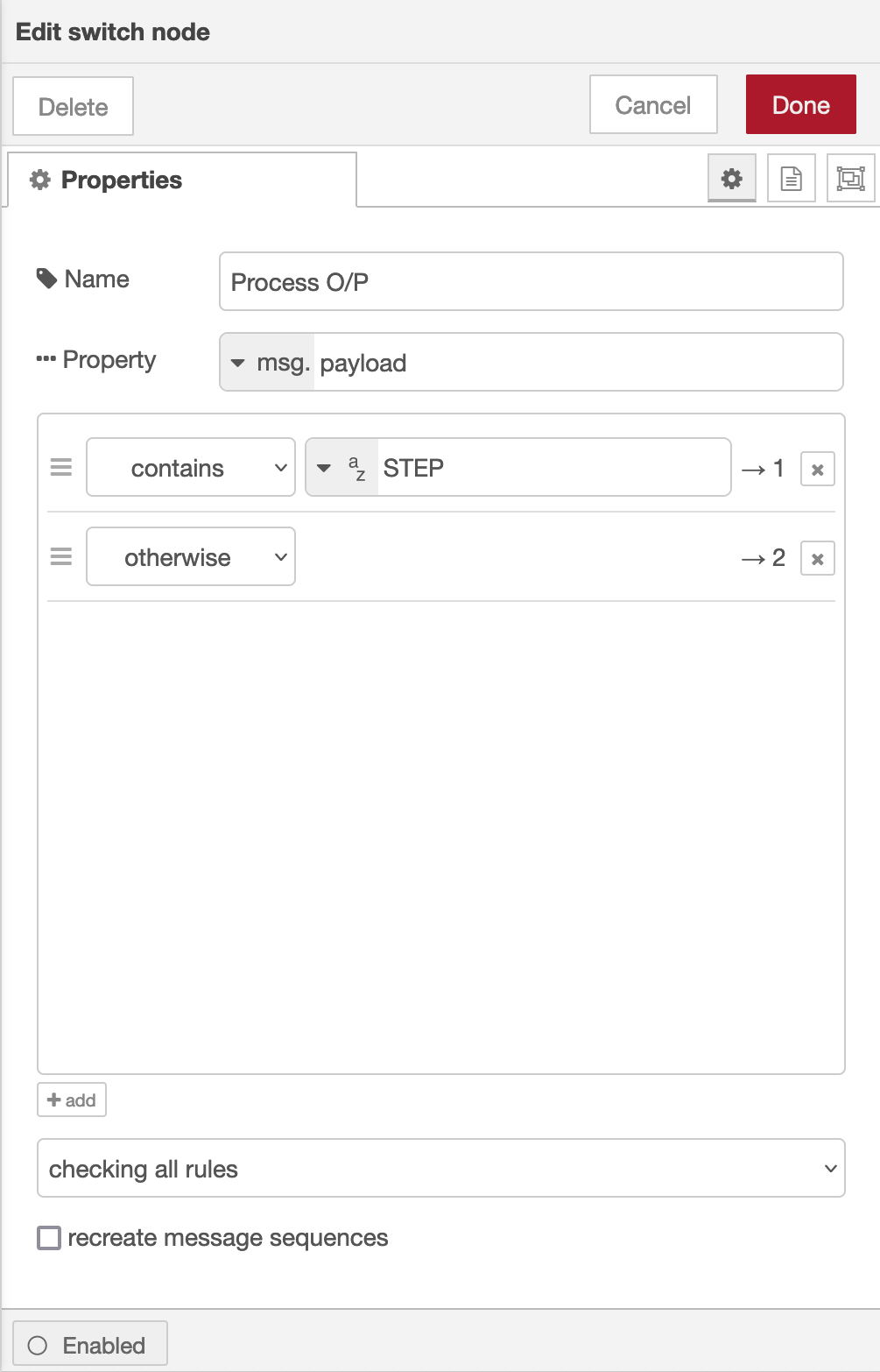
Having the need for full duplex operation on the satellite this complicates things when it comes to VFO tracking and general control of the two radios involved in the solution and so I set about creating a QO-100 Dashboard using the great Node-RED graphical programming environment to create a web app that simplifies the management of the entire setup.

M0AWS QO-100 ground Station Control Dashboard built using Node-RED.

The QO-100 Dashboard synchronises the transmit and receive VFO’s, enables split operation so that you can transmit and receive on different frequencies at the same time and a whole host of other things using very little code. Most of the functionality is created using standard Node-RED nodes. More info on Node-RED can be found on the Opensource.radio Wiki or from the menu’s above.

I’ll be publishing an article all about the QO-100 Dashboard in the very near future along with a downloadable flow file.

I’m extremely pleased with how well the ground station works and have had well in excess of 500 QSO’s on the QO-100 satellite over the last last year.

More soon …

Using AI to generate modern QSL Cards

With the recent explosion of artificial intelligence (AI) art generators that are making the news of late for all the wrong reasons, I decided to see if I could put it to good use and design some futuristic QSL cards.

Having recently been contacted by the Special Callsigns QSL Manager and being advised that there were 18 QSL cards waiting for me, I decided it was time to create some QSL cards of my own for future use.

Having never used any form of online AI and not having any artistic abilities I was amazed how easy it was to create images using nothing more than a paragraph or so of text to describe what it was I wanted to create.

Since all the QSL cards I received were for contacts on the QO-100 satellite, I set out to create a visually futuristic QSL card that was based around a radio HAM operator and satellite communications.

M0AWS - 1st attempt to create a futuristic QSL card using AI Art
M0AWS – 1st attempt at creating a futuristic QSL card image using AI Art

To my surprise the results of my first image generation were surprisingly good. The AI generated an image that resembled the simple text that I entered, although I never requested a one legged HAM operator!

Pleased with my very first attempt I gradually improved the description of what I was looking for, adding more and more detail to the text and including things that I wanted to see in the image. Over a fairly short period of time this approach started to generate some very interesting images.

With each iteration I gradually got closer to what I was trying to achieve but, never quite got exactly what I wanted so, I decided to rewrite the descriptive text adding even more information than before. The text was now a full blown paragraph with quite specific things described including the angle at which the scene was being viewed from.

The other option I wanted to try out was the theme functionality that the AI offered. This allows you to set a theme for the image from things like steampunk, cartoon, manga, real world and many more. The results were quite impressive and added yet another angle to the image generation.

I disappeared down the theme AI Art generation rabbit hole for quite some time and generated some very interesting and fun results. The best by far though was the Thunderbirds themed image, this did put a smile on my face!

M0AWS - AI Art QSL Thunderbirds Themed
M0AWS – AI Art QSL Thunderbirds Themed

At the other end of the spectrum I tried the Salvador Dalli theme, it produced an image that was very like the work of the famous artist but, wasn’t quite what I was looking for.

M0AWS - AI Art QSL Salvador Dalli Themed
M0AWS – AI Art QSL Salvador Dalli Themed

After much fun I eventually settled on the image I was after, a futuristic scene of a radio HAM with a satellite ground station over looking a mountain range and city below.

M0AWS Satellite QSL Card generated using online AI

I’m really pleased with the results from my ventures into AI generated art. The next challenge is to create a QSL card for HF bands Contacts.

More soon …

Update to my NodeRed QO-100 Dashboard

Ever since my QO-100 ground station has been operational I’ve been using my NodeRed QO-100 Dashboard to control my IC-705 and GQRX SDR software to drive my NooElec SmartSDR receiver. This gives me a full duplex ground station with both transmit and receive VFO’s synchronised.

This solution has worked incredibly well from the outset and over time I’ve added extra functionality that I’ve found to be useful to enhance the overall setup.

The latest addition to the ground station solution is a Sennheiser Headset that I picked up for just £56 on Amazon (Much cheaper than the Heil equivalents at the HAM stores!) and have found it to be excellent. The audio quality from both the mic and the headphones is extremely good whilst being light and comfortable to wear for extended periods.

M0AWS - Sennheiser SC 165
M0AWS – Sennheiser SC 165 Headset

To incorporate this into the ground station the headset is connected to my Kubuntu PC and the audio chain to the IC-705 is sent wirelessly using the latest version of WFView. This works extremely well. The receive audio comes directly from the GQRX SDR software to the headphones so that I have a full duplex headset combination.

Audio routing is done via pulse audio on the Kubuntu PC and is very easy to setup.

Since I no longer have a mic connected to the IC-705 directly I found that I needed a way to operate the PTT wirelessly and this is where the latest addition to my NodeRed QO-100 Dashboard comes in.

Adding a little functionality to the NodeRed flow I was able to create a button that toggles the IC-705 PTT state on and off giving me the ability to easily switch between receive and transmit using a simple XMLRPC node without the need for a physical PTT button.

M0AWS - Additional NodeRed PTT Flow
M0AWS – Additional NodeRed PTT Flow

The PTT state and PTT button colour change is handled by the Toggle PTT function node shown in the above flow. The code to do this is relatively simple as shown below.

M0AWS - NodeRed Toggle PTT Function to change button colour
M0AWS – NodeRed Toggle PTT Function to change button colour

The entire QO-100 Dashboard flow has grown somewhat from it’s initial conception but, it provides all the functionality that I require to operate a full duplex station on the QO-100 satellite.

M0AWS - NodeRed QO-100 Dashboard complete flow
M0AWS – NodeRed QO-100 Dashboard complete flow

This simple but, effective PTT solution works great and leaves me hands free whilst talking on the satellite or the HF bands when using the IC-705. This also means that when using my IC-705 it only requires the coax to be connected, everything else is done via Wifi keeping things nice and tidy in the radio shack.

M0AWS - Updated NodeRed QO-100 Dashboard with PTT button
M0AWS – Updated NodeRed QO-100 Dashboard with PTT button

The image above shows the QO-100 ground station in receive cycle with the RX/TX VFO’s in split mode as the DX station was slightly off frequency to me. The PTT button goes red when in TX mode just like the split button shown above for visual reference.

As you can probably tell, I’m a huge fan of NodeRed and have put together quite a few projects using it, including my HF Bands Live Monitoring web page.

More soon …

Home-Brew 12v DC Distribution Box

I’ve been wanting to tidy up the cabling to the 12v DC PSU for some time in the radio shack as like many HAMs I have a number of radios/devices that all need a 12v feed but, only two connectors on the front of the PSU. The net result was a birds nest of wires all connected to the PSU making it impossible to disconnect one device without others getting disconnected at the same time.

Looking online I found that many of the HAM outlets stores sell nice little 12v DC distribution boxes that would be ideal however, they’re all priced somewhat high for what they are so, I decided to purchase the parts and make one myself.

Searching on Amazon I found all the necessary parts for less than a quarter of the cost of commercially made units. A couple of days later the parts arrived and sat on my desk in the shack for a few weeks. Yesterday I finally found the time to make a start on the project.

M0AWS home-brew 12v DC Distribution Box

After much drilling and filing I had the necessary holes/slots cut in the plastic box for the 4mm connectors and fuse holders and started wiring them up. Part way through my 30 year old soldering iron decided to die and so I had to stop and wait for a replacement to arrive.

M0AWS completed 12v DC Distribution Box

With the new soldering iron in hand it only took 30mins or so to complete all the joints and I soon had the box together ready to test with my multimeter to ensure I didn’t have any shorts or crossed wires.

With testing complete and fuses in place I connected it up to the PSU and then connected all the devices one by one checking for voltage drops as I went.

M0AWS 12v DC Distribution Box

I now have my CG3000 remote auto ATU, GPSDO, QO-100 ground station and IC-705 all nicely connected in a much tidier fashion than before, all for considerably less than the commercially available alternatives.

More soon …

My old valve radio station

Going through some old photos today I found a few great memories from the past of my old valve radio stations that I’d restored over the years.

These old radios gave me some wonderful moments over the years and a fair few hours of restoration to get them into operational condition. They sounded great on air and I often got comments from other amateur stations about how warm the audio sounded. Some did also mention the drift of the transmitter with temperature changes but, you just have to accept that when using vintage radio equipment.

M0AWS FT101E Transceiver, FL101 Transmitter, FR101B Receiver and TS520S Transceiver.

Above is my old FT101 line up. It consisted of the great FT101E transceiver, a complete standalone solution that was extremely popular in its day. Below it is the FT101 line up made up of the FT101 transmitter, FR101B receiver and matching speaker.

Top right is the lovely Trio TS520S with the matching digital frequency display which is incredibly rare and very sought after today.

These radios gave me a lot of pleasure for many years and I wish I still had them today.

My second Yaesu valve line up took a lot more restoration than the 101 series and was quite challenging at times but, with a lot patience and time spent sourcing parts I got them back to as close to new operational condition as was possible.

M0AWS FLDX400 Transmitter, FRDX400 Receiver, FL2000B Amplifier and FTDX501 Transceiver.

The Yaesu 400 series line up consisted of the FLDX400 transmitter, FRDX400 receiver and was finished off with the FL2000B amplifier. These 3 pieces of radio equipment looked beautiful in the flesh and were wonderful to operate. Taking a good 15mins to warm up and become stable you couldn’t rush getting on air. This line up was my favourite by far even though they weren’t as good as the 101 line up.

Above the 400 series is the later FTDX501 transceiver with matching speaker. This was a great radio in its own right but, not as much fun to operate as the 400 line up. To the right of the FTDX501 is the matching Yaesu Microphone for the 400/500 series. This mic is incredibly rare and I had to visit many radio swap rallies to find it, worth the effort though.

Top right you can see my old SWL receiver, the great Drake SW4A. I never had a Drake line up as they are quite rare in the UK but, it certainly would had made a great addition to the station.

M0AWS FLDX400, FRDX400 & FL2000B Station being operated by M1ACB and G6ALB

Finally this is a photo of two friends of mine, Steve Thomas M1ACB (Current General Manager of the RSGB) on the right and Andy, G6ALB with whom I spent many hours sending and receiving morse with to get our Class A licences. We had a fun day together operating the old radios and taking it in turns to handle the pile ups!

More soon …

My First QO-100 Satellite QSO

I’ve been waiting for over a week so far for a male to male SMA connector to arrive from Amazon so that I can connect the 2.4Ghz up-converter to the 2.4Ghz amplifier. Since it still hasn’t arrived I decided to connect the up-converter directly to the IceCone Helix antenna to see if I could get a signal into the QO-100 satellite.

To my surprise I could easily hear my CW signal on QO-100 even though the total output from the up-converter is only 200mW.

I didn’t expect to be able to hear my signal since it’s a tiny amount of power that has to travel some 22500 miles to the satellite but, I could hear it and was amazed that it was peaking S8 on my SDR receiver.

2.4Ghz Up-COnverter connected directly to the antenna bypassing the 2.4Ghz Amplifier
2.4Ghz Up-Converter connected directly to the antenna bypassing the 2.4Ghz Amplifier

Being excited I put out a CQ call that was soon answered by OH5LK, Jussi in Finland. Jussi gave me a 579 report which I was extremely pleased with. He was of course much stronger at a 599+ at my end. We had a quick QSO and exchanged details without any problems at all. Its really nice to get a QRPp contact without any QSB or QRM.

M0AWS QO-100 1.1m off-set Dish and IceCone Helix antenna ground station

Neil, G7UFO who I chat with regularly in the Matrix Amateur Radio Satellites room has posted a connector out to me so I’m hoping it will arrive on Monday and then I’ll be able to connect the amplifier and hopefully get a few SSB contacts.

UPDATE: I’ve since had 2 SSB contacts via QO-100 using just the 200mW O/P from the up-converter. Both times I got a 3/3 report not brilliant but, perfectly acceptable for the amount of power I’m putting out.

More soon …

Replacement for the Funcube Dongle Pro+

For some time now I’ve been using my Funcube Dongle Pro+ (FCD) as my QO-100 downlink receiver. It’s worked fairly well and has given me the ability to listen to stations on the satellite over the last few months.

During this time I have noticed a couple of things about the FCD that has lead me to the final decision to change to a new SDR device.

The first of these ‘things’ is the fact that the FCD gets seriously overloaded when there are multiple large SSB signals within the receive pass band. The only way to manage this is to constantly keep changing the software based AGC, mix and LNA settings to reduce the levels of the incoming signals so that the overloading stops. This is great except when you tune to a quiet part of the satellite transponder you have to turn all the settings back up again to be able to hear the weaker signals. After a while this becomes tiresome.

The fact that there isn’t a hardware AGC in the FCD is a major drawback when being used for satellite reception especially when it’s on the end of a very high gain LNB and dish antenna.

The second of these ‘things’ is the fact that I can’t see the whole transponder bandwidth at one time with the FCD as it has a very small receive bandwidth capability. This means that I am constantly tuning up and down the transponder to see if there are any stations further up or down in frequency.

Funcube Dongle Pro+
Funcube Dongle Pro+

Talking to more experienced satellite operators in the Matrix Amateur Radio Satellites room they recommended replacing the FCD with a NooElec NESDR SMArt v5 that has hardware AGC and is capable of receiving and displaying a much wider bandwidth.

Looking on Amazon the NooElec NESDR SMArt v5 is only £33 so I decided to place an order for one and give it try.

In typical Amazon style the SDR receiver arrived the next day and I wasted no time getting it plugged in and connected to the QO-100 ground station.

The NESDR SMArt v5 is based on the well known RTL-SDR that came onto the market some time back but, has a number of improvements in it that take it to the next level.

The first thing that I was happy with was the fact that the GQRX SDR software I use recognised it immediately on startup, no configuration or drivers were required it just worked, straight out of the box. Since I use Kubuntu Linux on my radio room PC I did wonder if I would need to get into installing extra libraries etc but, thankfully none of that was required.

Looking at the signals from the QO-100 satellite initially they appeared to be nowhere near as strong as they were on with the FCD. Looking at the settings in GQRX I noticed that the hardware AGC was off and the LNA setting was back to it’s default very low level.

I switched on the AGC and then increased the LNA setting to 38.4dB and found that the signals were now plenty strong enough on the display but, not overloading the receiver.

I then went on to adjust the display so that I could see the whole satellite transponder bandwidth on the screen. This is great as it enables me to see the low, middle and high beacons that mark out the narrow band section of the transponder and at a glance see all the stations using the satellite. This was a massive improvement in itself and one that I am very pleased with.

Using the NooElec NESDR SMArt v5 SDR it very soon became clear that it copes with multiple large signals in the pass band so much better than the FCD did. There’s no more overloading of the receiver, no more ghost signals appearing on the waterfall due to the front end not being able to cope and no more having to constantly keep playing with the settings to get things under control. The hardware AGC built into the SDR device does a great job at keeping it all under control whilst receiving a much wider bandwidth than the FCD ever could.

The satellite beacons are now received at S9+15dB without the receiver being overloaded, the first time I have seen this since starting out on my QO-100 venture.

The other thing that became obvious very quickly is that frequency stability is much better than it was with the FCD, it doesn’t drift up and down the transponder now and stays tuned exactly where I put it. It’s also on frequency whereas, the FCD was always 1.7Khz off frequency.

GQRX showing QO-100 Transponder signals

The NooElec NESDR SMArt v5 is very well put together, it has an aluminium case that acts as a heatsink (it does get warm!) and overall the build quality is much better than the plastic cased FCD. When I think that I paid close to £100 for the FCD and the NooElec NESDR SMArt v5 only cost £33, I am amazed at the build quality.

Overall I’m extremely pleased with the purchase of the new SDR, it slotted in perfectly as a replacement for the FCD, works great with GQRX, my QO-100 Node Red Dashboard and performs considerably better than the FCD. Overall money well spent!

You can find the NooElec NESDR SMArt v5 spec sheet here.

More soon …

Use a Griffin Powermate with SDR via Node Red

I’ve been gradually building my QO-100 ground station over the last few months and have had the receive path working for some time now. One of the things I really miss with the Funcube Dongle Pro+ (FCD) SDR is a real VFO knob for changing frequency.

My QO-100 Node Red dashboard is configured so that I can have the FCD track the uplink frequency from the IC-705 but, sometimes I use the FCD without the IC-705 in the shack and so a physical VFO would be handy.

Many years ago when I lived in France (F5VKM) I had a Flexradio Flex-3000 SDR, a great radio in it’s time and one that gave me many hours of enjoyment. One addition I bought for that station was a Griffin Technology Powermate VFO knob. It worked extremely well with the PowerSDR software for the Flex-3000 and I used it for many years.

Many years later I’m back in the UK and much of my equipment is packed away in the attic, including the Griffin Technology Powermate VFO.

I decided to dig it out and see if I could get it working with GQRX SDR software. Sadly I couldn’t get it working with GQRX however, I did find a way of getting it working with Node Red and thus could add it to my QO-100 Node Red Dashboard and then control GQRX with it via a simple Node Red flow.

Griffin Technology Powermate VFO

Plugging the Powermate VFO into my Kubuntu PC it wasn’t immediately recognised by the Linux O/S. After a little searching I found the driver on Github. I added the PPA to my aptitude sources and installed the driver using apt.

https://launchpad.net/~stefansundin/+archive/ubuntu/powermate

Once installed the default config for the Powermate device is to control the default audio device volume. To make the device available for use as a VFO knob you need to change the configuration so that the default setting is disabled. To do this is relatively easy, just edit the config file using your favourite command line editor (Vi/Vim in my case) and add the following entry.

vi /etc/powermate.toml

# Entry to control HDMI volume with Powermate
#sink_name = "alsa_output.pci-0000_01_00.1.hdmi-stereo"

# Set powermate not to work with volume control
sink_name = ""

As shown above, comment out the default “sink_name” entry (Yours may be different depending on audio device in your PC) and add in the Powermate “sink_name” entry that effectively assigns it to nothing.

Once this is done, save the file and exit your editor and then reboot the PC.

Next you’ll need to install a small program called evtest.

sudo apt install evtest

To check the evtest program has installed correctly, plugin your Powermate VFO to any available USB port and run the following command in a terminal.

evtest /dev/input/powermate

Turning the Powermate knob you should see output on the screen showing the input from the device. You should also see BTN events for each press of the Powermate device.

Input driver version is 1.0.1
Input device ID: bus 0x3 vendor 0x77d product 0x410 version 0x400
Input device name: "Griffin PowerMate"
Supported events:
  Event type 0 (EV_SYN)
  Event type 1 (EV_KEY)
    Event code 256 (BTN_0)
  Event type 2 (EV_REL)
    Event code 7 (REL_DIAL)
  Event type 4 (EV_MSC)
    Event code 1 (MSC_PULSELED)
Properties:
Testing ... (interrupt to exit)
Event: time 1685816662.086666, type 2 (EV_REL), code 7 (REL_DIAL), value -1
Event: time 1685816662.086666, -------------- SYN_REPORT ------------
Event: time 1685816662.318638, type 2 (EV_REL), code 7 (REL_DIAL), value -1
Event: time 1685816662.318638, -------------- SYN_REPORT ------------
Event: time 1685816662.574615, type 2 (EV_REL), code 7 (REL_DIAL), value -1
Event: time 1685816662.574615, -------------- SYN_REPORT ------------
Event: time 1685816663.670461, type 2 (EV_REL), code 7 (REL_DIAL), value 1
Event: time 1685816663.670461, -------------- SYN_REPORT ------------
Event: time 1685816664.030421, type 2 (EV_REL), code 7 (REL_DIAL), value 1
Event: time 1685816664.030421, -------------- SYN_REPORT ------------
Event: time 1685816664.334389, type 2 (EV_REL), code 7 (REL_DIAL), value 1
Event: time 1685816664.334389, -------------- SYN_REPORT ------------
Event: time 1685816665.334255, type 1 (EV_KEY), code 256 (BTN_0), value 1
Event: time 1685816665.334255, -------------- SYN_REPORT ------------
Event: time 1685816665.558230, type 1 (EV_KEY), code 256 (BTN_0), value 0
Event: time 1685816665.558230, -------------- SYN_REPORT ------------
Event: time 1685816666.030161, type 1 (EV_KEY), code 256 (BTN_0), value 1
Event: time 1685816666.030161, -------------- SYN_REPORT ------------
Event: time 1685816666.182151, type 1 (EV_KEY), code 256 (BTN_0), value 0
Event: time 1685816666.182151, -------------- SYN_REPORT ------------

At this point you’re ready to stop evtest (CTRL-C) and then create the following little BASH shell script that Node Red will run to collect the O/P from the Powermate USB device.

#!/bin/bash

###############################################
# Griffin Technology Powermate control script #
# for Node Red.                               #
#                                             #
# 04/06/23 - M0AWS - v0.1                     #
#                                             #
###############################################

VAL="1"
echo "STEP-1Hz"

/usr/bin/evtest /dev/input/powermate | while read LINE 
do
   case $LINE in

      *"(REL_DIAL), value 1") echo "$VAL"
           ;;

      *"(REL_DIAL), value -1") echo "-$VAL"
           ;;

      *"(BTN_0), value 1") case $VAL in

                              "1") VAL="10"
                                   echo "STEP-10Hz"
                                      ;;

                             "10") VAL="100"
                                   echo "STEP-100Hz"
                                      ;;

                             "100") VAL="1000"
                                    echo "STEP-1Khz"
                                       ;;

                             "1000") VAL="10000"
                                     echo "STEP-10Khz"
                                         ;;

                             "10000") VAL="1"
                                       echo "STEP-1Hz"
                                          ;;
                              esac
                                 ;;
        esac
done

Once the BASH script is copied and pasted into a file called powermate.sh you need to make it executable by using the following command.

chmod 700 ./powermate.sh

If you now run the shell script in a terminal you’ll see a similar output to that shown below from the device when used.

./powermate.sh 
STEP-1Hz
-1
-1
-1
1
1
1
STEP-10Hz
10
10
10
-10
-10
-10
STEP-100Hz
100
-100
-100
STEP-1Khz
1000
STEP-10Khz
STEP-1Hz
1
1
STEP-10Hz

As you can see above the shell script outputs a positive or negative number for VFO tuning and changes the VFO step size each time the Powermate is depressed.

Getting this output from the BASH shell script into Node Red is really simple to achieve using just 3 or 4 nodes.

In the Node Red development UI create the following nodes.

Griffin Powermate Node Red Nodes

The first node in the flow is a simple inject node, here I called it trigger. This sends a timestamp into the next node in the flow at startup to set the flow running.

The Griffin Powermate node is a simple exec node that runs the script we created above.

M0AWS Powermate exec node

Configure the node as shown above and connect it to the inject node that’s used as a trigger. Note: Change “user” in the Command field shown above to that of your username on your Linux PC)

Once done create the third node in the flow, a simple switch node and configure as shown below.

Switch Node for Powermate

The switch node has two outputs, the top one is a text output that is fed into a text field to show the current step size of the Powermate device and the lower output is the numeric output that must be fed into your VFO control flow so that the VFO value is incremented/decremented by the amount output by the Powermate device.

I’ve found the Griffin Technology Powermate USB device works extremely well with Node Red and GQRX that I use for controlling the FCD SDR radio and it’s now part of my QO-100 ground station build.

M0AWS QO-100 Dashboard with Powermate Step Display at bottom

As shown above you can see the Powermate Step size at the bottom of the dashboard, this text changes each time the Powermate device is depressed and will set a step size of 1Hz, 10Hz, 100Hz, 1Khz, 10Khz in a round-robin fashion.

The next stage of the build is the 2.4Ghz transmit path. I now have all the necessary hardware and so this part of the build can finally commence.

More soon …

20m – 10m Bi-Directional Slot Fed Antenna

The bi-directional slot fed HF antenna isn’t mentioned very often these days for some strange reason. It’s a real shame as it is an excellent antenna that gives high gain through the loop between the frequencies of 14Mhz and 29Mhz.

M0AWS 20m - 10m HF Slot Antenna
M0AWS 20m – 10m Slot Fed HF Antenna

Construction of the antenna is relatively simple, 3 x 3m long horizontal wires and 2 x 9.2m long vertical wires. I’ve modelled the antenna using 20mm diameter copper tubing for the horizontal conductors and 2.5mm wire for the two vertical conductors. Using the 20mm copper tubing provides a rigid platform for the mounting of the antenna on a non-conductive mast whilst reducing weight by using 2.5mm wire for the vertical conductors. You could of course use 20mm copper tubing for all the conductors if you have a non-conductive mast that can handle the weight.

An alternative option is to hang the antenna from a high tree and secure it in position with non-conductive nylon cord. This works very well and makes it extremely easy to manually rotate.

The antenna is fed at the centre of the middle horizontal tube (conductor 2 in the image above) using one of the following methods:

Method 1 – Use a 4:1 Balun and ATU either in the radio/Radio Shack or connected directly to the Balun. Connecting a remote auto ATU to the balun directly at the feed point is the best option as you will then have a perfect 50 Ohm impedance match to the coax cable going back to the radio. (I’ve used my AH-705 and a 4:1 Balun at the feed point in the past with excellent results).

Method 2 – Connect a remote auto ATU directly to the feed point of the antenna and then 50 Ohm coax back to the radio shack. This will provide a perfect SWR match on all bands and works extremely well. (I’ve used my AH-705 remote auto ATU in this configuration as well in the past, again with excellent results and no discernible difference to method 1).

Method 3 – Feed the antenna with 450 Ohm open ladder line and use a 4:1 Balun and ATU in the radio shack to match the antenna to 50 Ohm radios. It’s important to bring the 450 Ohm ladder line away from the feed point horizontally and not vertically downwards. This will then help to protect the radiation pattern.

Looking at the 2D Far Field Plots this antenna provides excellent gain at relatively low radiation angles on all bands 20m – 10m making it an ideal antenna for chasing DX.

20m Band 2D Far Field Plot
17m Band 2D Far Field Plot
15m Band 2D Far Field Plot
12m Band 2D Far Field Plot
10m Band 2D Far Field Plot

The gain on each band is as follows:

20m Band – 7.83dBi at 24 Degrees
17m Band – 9.07dBi at 20 Degrees
15m Band – 9.63dBi at 16 Degrees
12m Band – 10.36dBi at 14 Degrees
10m Band – 10.99dBi at 12 Degrees

10m Band 3D Far Field Plot

The 10m Band 3D Far Field Plot above shows the typical radiation pattern for the antenna. Maximum radiation is through the loop with very little high angle radiation making it ideal for chasing DX stations. Gain increases as frequency increases however, angle of maximum radiation decreases as frequency increases improving DX capability of the antenna on the higher bands. It’s worth ensuring that the antenna is rotatable as this will then enable you to point the antenna at the DX station to maximise signal strength at the DX end. Pointing this antenna North/South makes it great for working VK/ZL over the North Pole whilst at the same time being able to work South Africa from the UK.

Summary:

Horizontal Wire Lengths: 3m @ 20mm Diameter
Vertical Wire Lengths: 9.2m @ 2.5mm Diameter
Modelled Height above ground at Centre (Conductor 2): 10.6m
Feed Type: 4:1 Balun + ATU / Remote Auto ATU / 450 Ohm Ladder line with 4:1 Balun & ATU