QO-100 Satellite Ground Station Build

Over the long bank holiday weekend I started putting together my QO-100 ground station. To start with I’ve concentrated solely on the receive path. I’ll start the transmit path once I have the receive path operational at a satisfactory level.

A few weeks ago I purchased a 1.1m off-set dish antenna and a Bullseye LNB. These have been sat in my garage waiting for the weather to improve so that I could start the build in the dry.
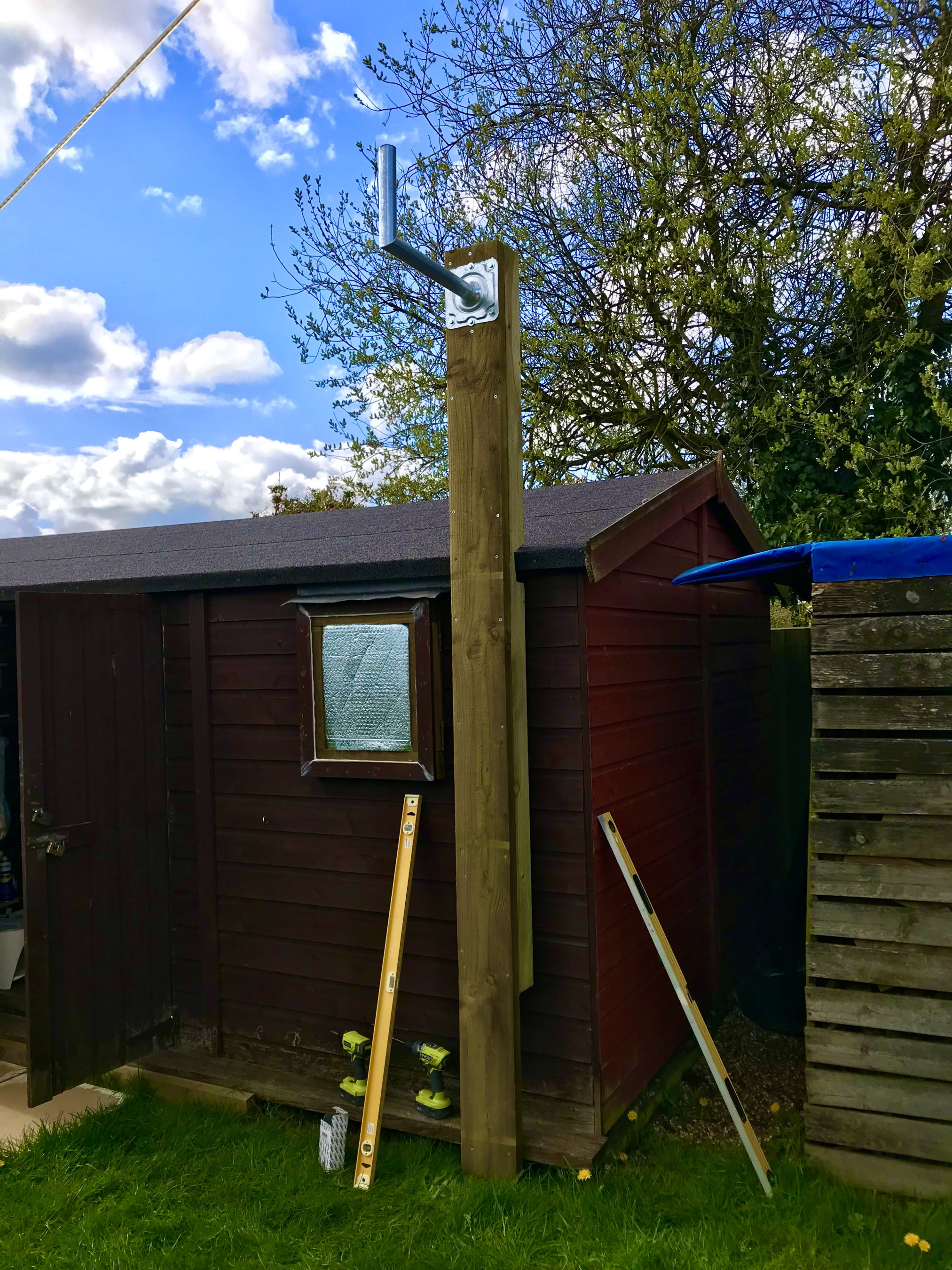
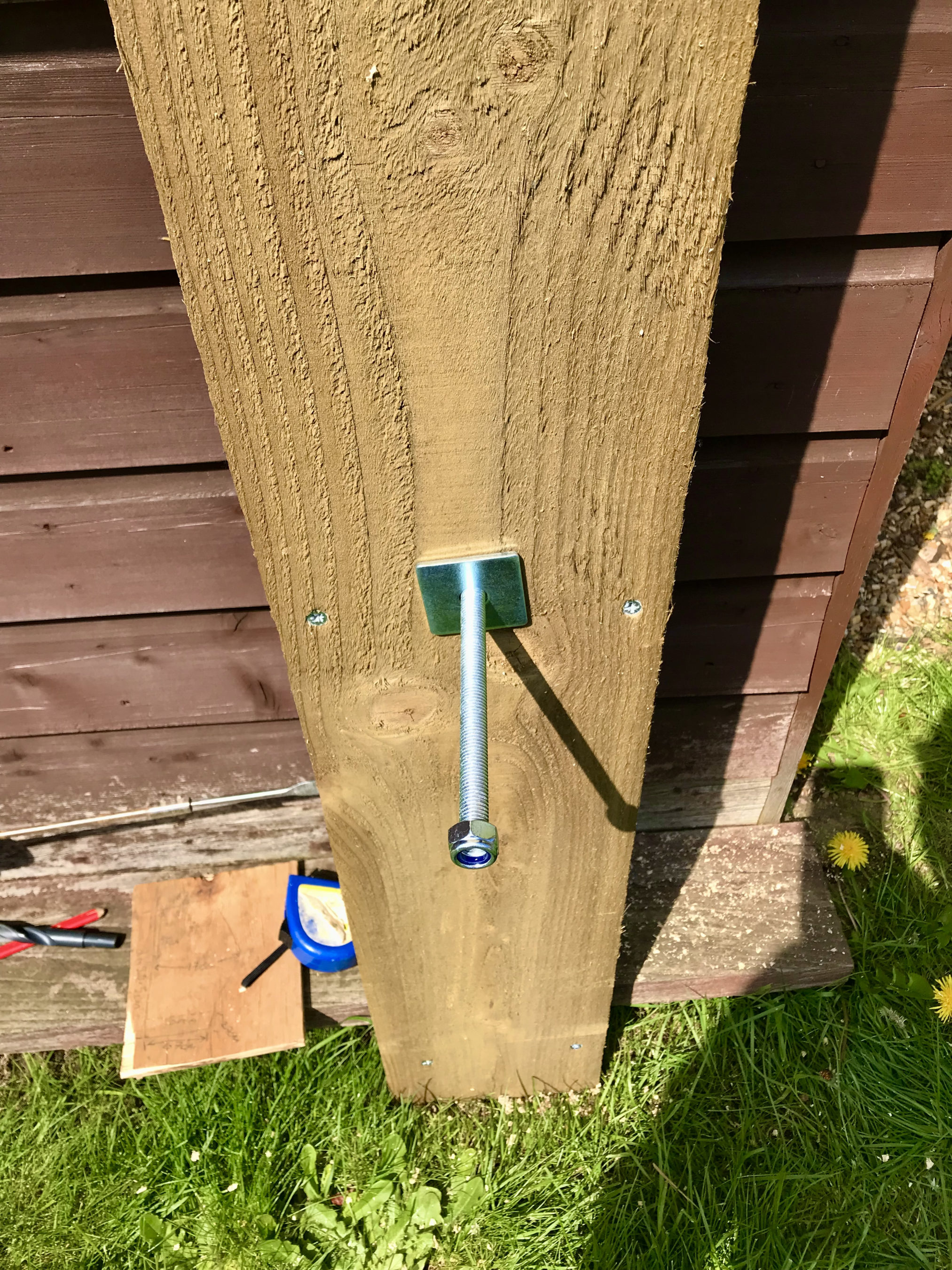
Fortunately we’ve had a mini-summer for the last 2 days and so I started work on getting the dish mount built. Using some timber from the local saw mill I made a braced 3m tall post which I screwed to the side of the cabin to provide a stable fixing platform. I used a couple of threaded bars to bolt through the walls of the cabin to ensure a solid fixing.

Next I mount the metal dish bracket to the top of the wooden post taking the total height up to around 3.2m above ground. This gives plenty of head clearance down below.

Next I assembled the dish and and attached it to the metal dish bracket at the top of the wooden post.
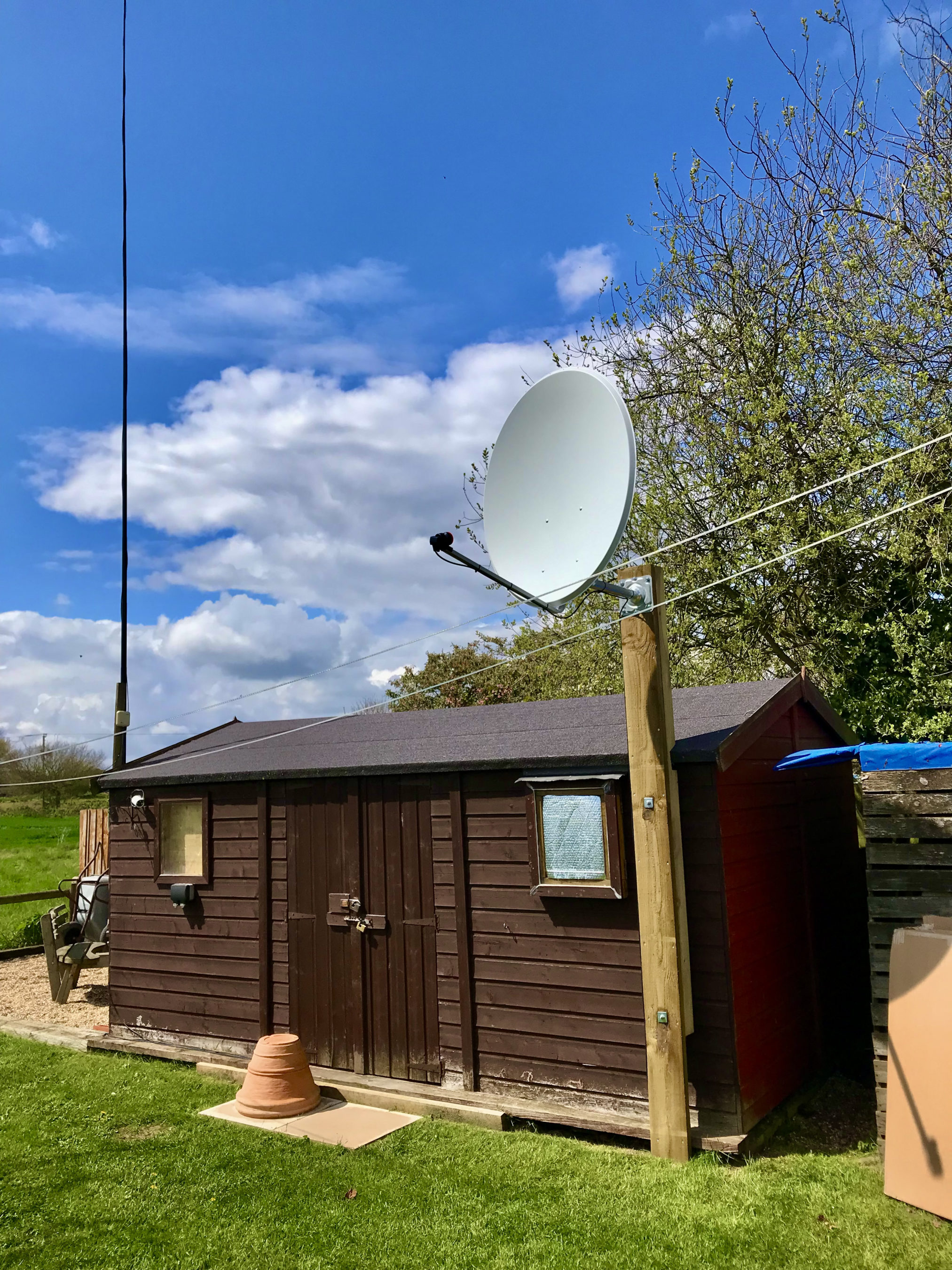
QO-100 1.1m dish mounted on the 3.2m AGL fixing

Attaching and cabling the Bullseye LNB was an easy job. I used some high quality coax cable that I purchase from the Satellite Superstore when I purchase the dish. I also had to set the LNB skew to -17.8 degrees. The marking on the LNB are tiny and go up in fives and so it’s pretty much impossible to get exactly -17.8 degrees so I turned it to 15 and then a tiny bit. It was as close I could get it!

Next I needed the information on where to point the dish. Fortunately there is a great web app on the BATC website where you can move a pin on a map to your location and all the information you need to align the dish is automagically calculated for you.

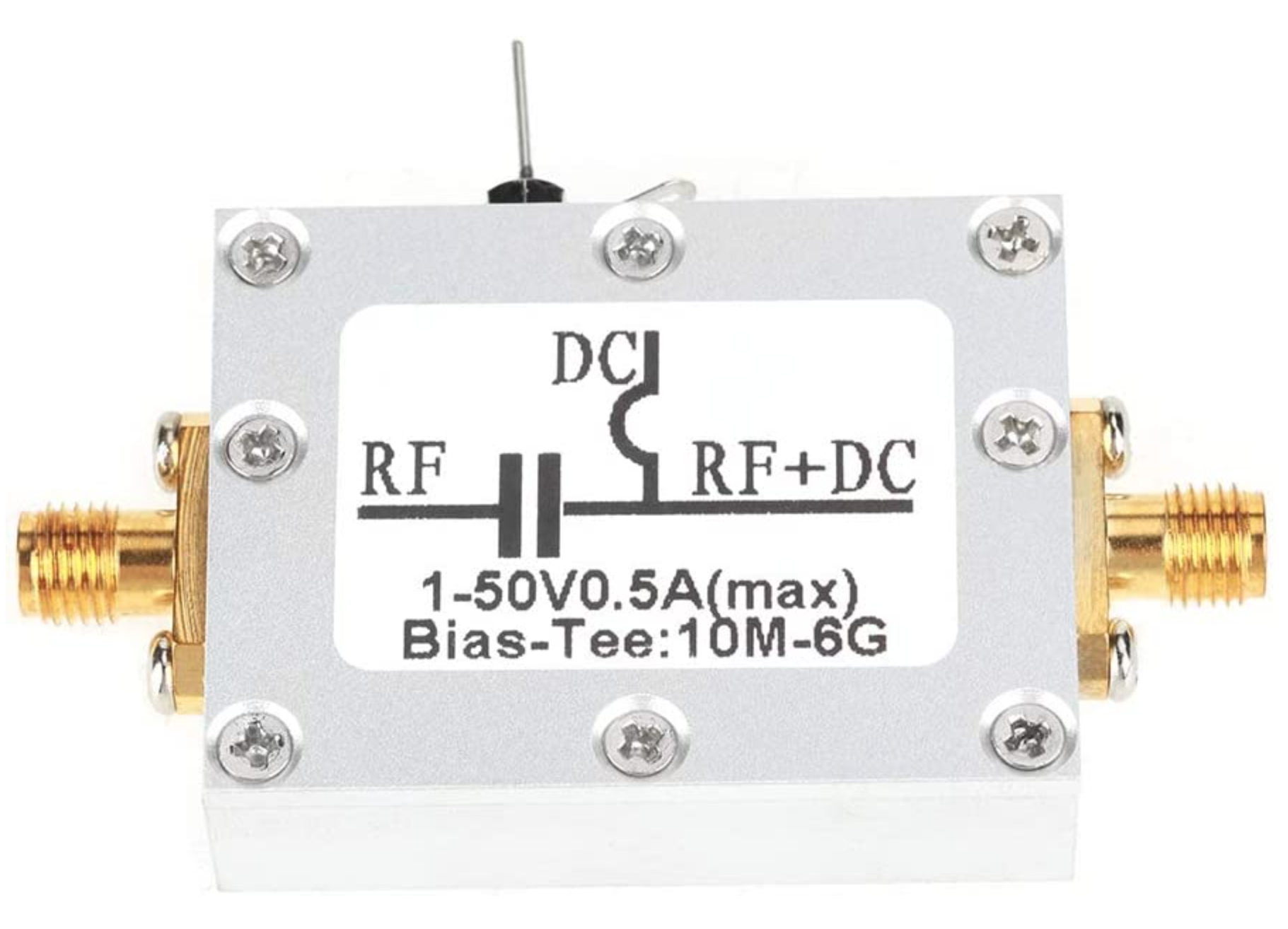
Armed with this info I set about aligning the dish. Getting it as close as possible I lightly locked off the dish and continued getting the coax in to the radio room so that I could connect it to my Funcube Dongle Pro+ (FCD) SDR receiver. Since the LNB needs a 12v DC feed I had to put inline a “Bias Tee” unit. This unit allows you to inject 12v onto the coax going up to the LNB but, stops it from coming back into the receiver. I used a Bias Tee that I purchased from Amazon with the Bullseye LNB.
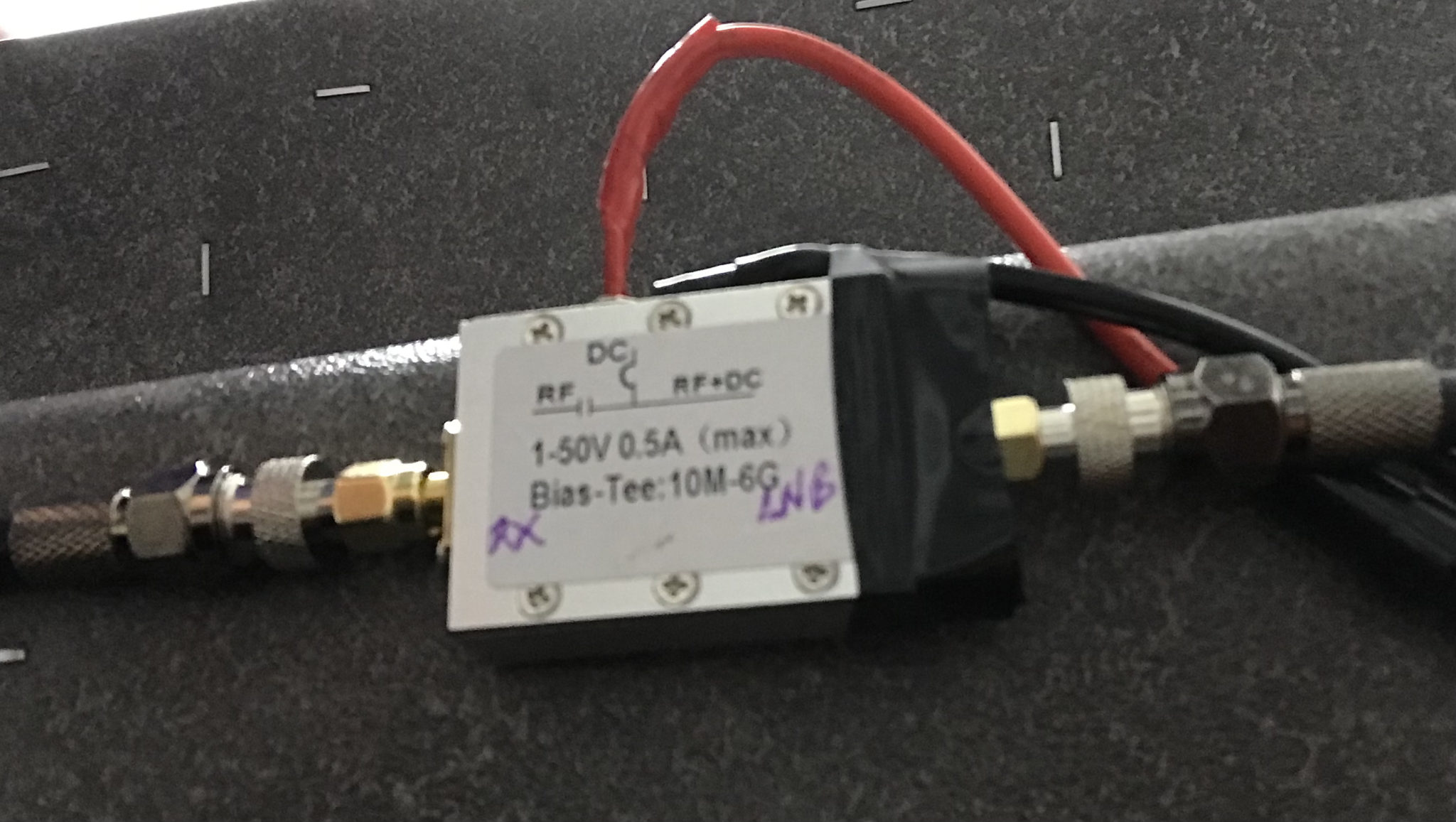
Bias Tee mounted under the station desk

Connecting the coax to my Funcube Dongle Pro+ I was really pleased to see that I was receiving signals from the satellite perfectly well. I decided to take my laptop up onto the roof of the cabin and see if I could improve the reception further. To my amazement with very tiny changes in elevation and azimuth I was able to improve the QO-100 beacon signal by a further 10dB.

Being pleased with the dish alignment I started to tighten it so that it couldn’t move in the wind. Unfortunately this caused the dish to move a tiny amount which reduced the signal strength. I loosened the bolts off again and realigned the dish once more. This time when I tightened the clamps I did it a bit at a time on each bolt working my way round them so that the dish didn’t move. Doing it this way I still lost 1dB off the QO-100 beacon signal due to tiny amounts of movement but, decided I could live with the 1dB reduction.
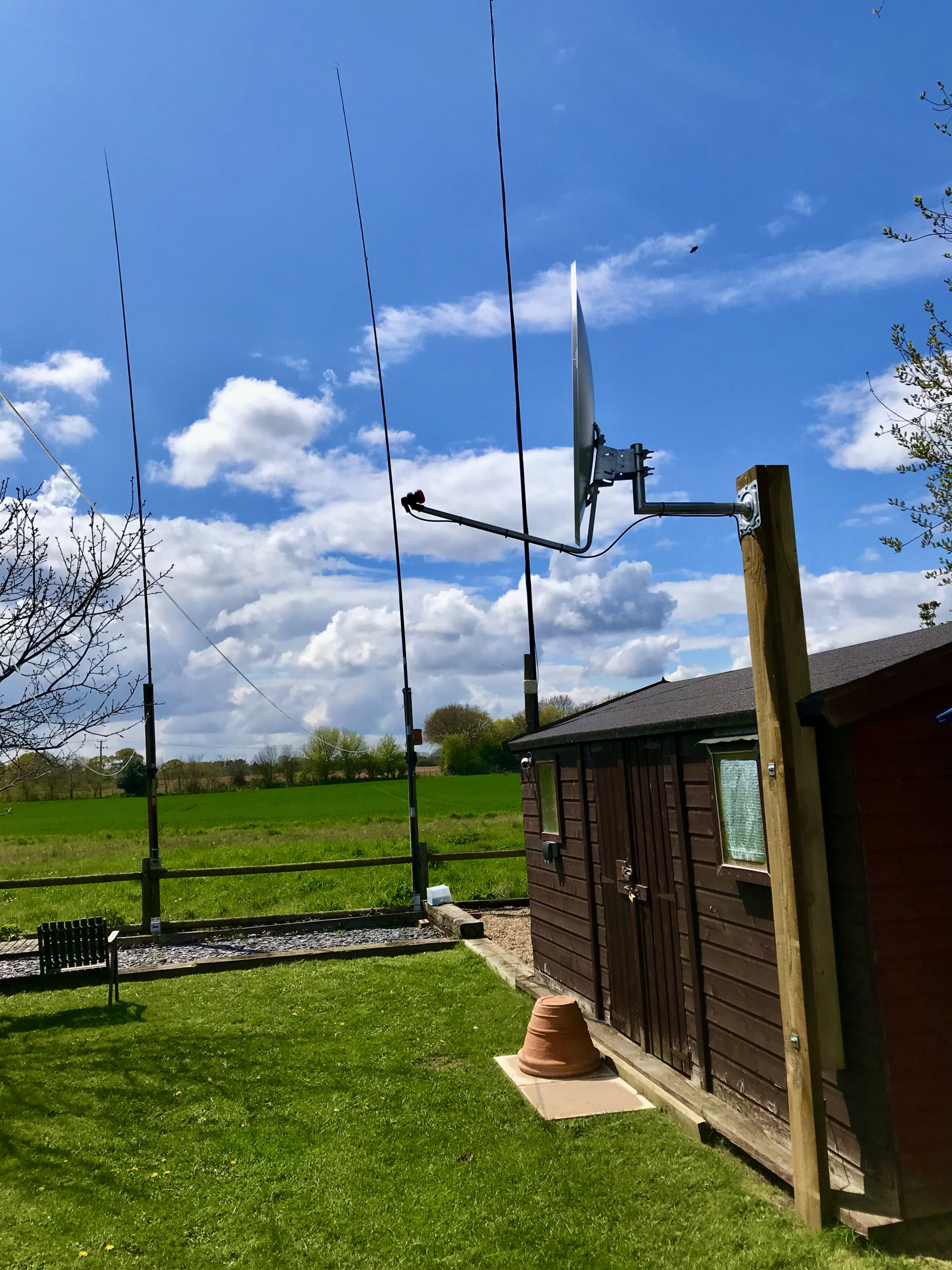
QO-100 dish successfully mounted & aligned with HF antennas in the background

Below is a very short video clip showing a German station talking on the QO-100 satellite. As you can see the signal is nice and strong and extremely clear. I did find that the output from the LNB was actually too much for the FCD SDR and so I reduced the LNA setting in GQRX to 0dB. This reduced the background noise level considerably as the receiver was no longer being overloaded and made the signals much more prevalent above the noise floor.

Short video clip showing signal clarity from the QO-100 Satellite

I’m really pleased at the performance of the receive path and have now ordered the 2.4Ghz hardware from DXPatrol and Nolle Engineering so that I can build the transmit path.

I have also made some improvements to my QO-100 Node Red Dashboard so that I can work split on the satellite using my IC-705 and FCD SDR.
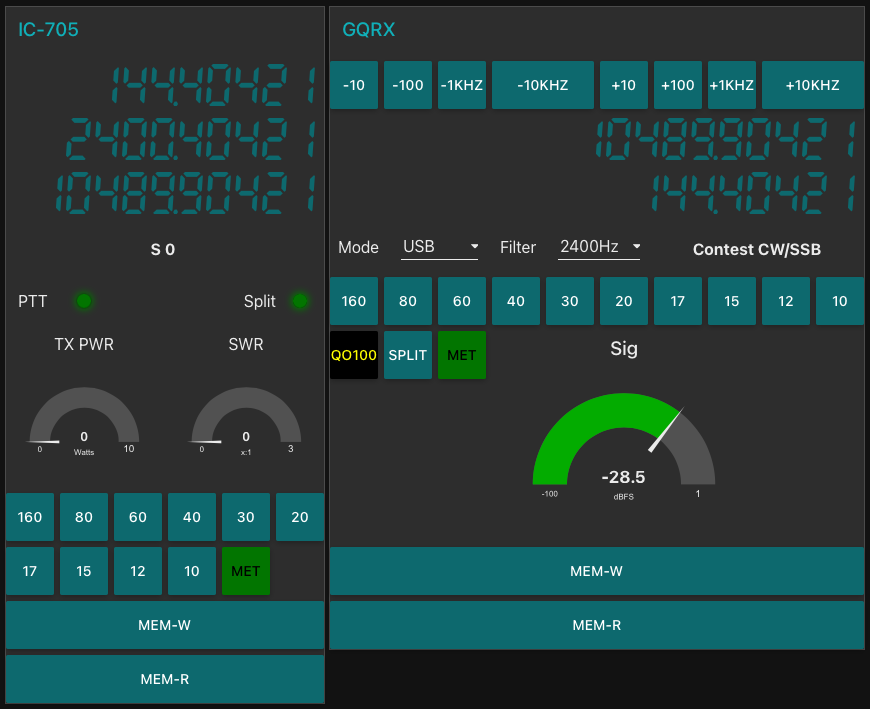
QO-100 Node Red Dashboard with ‘Split’ capability

Once the 2.4Ghz hardware arrives I’ll update the blog with progress.

More soon …
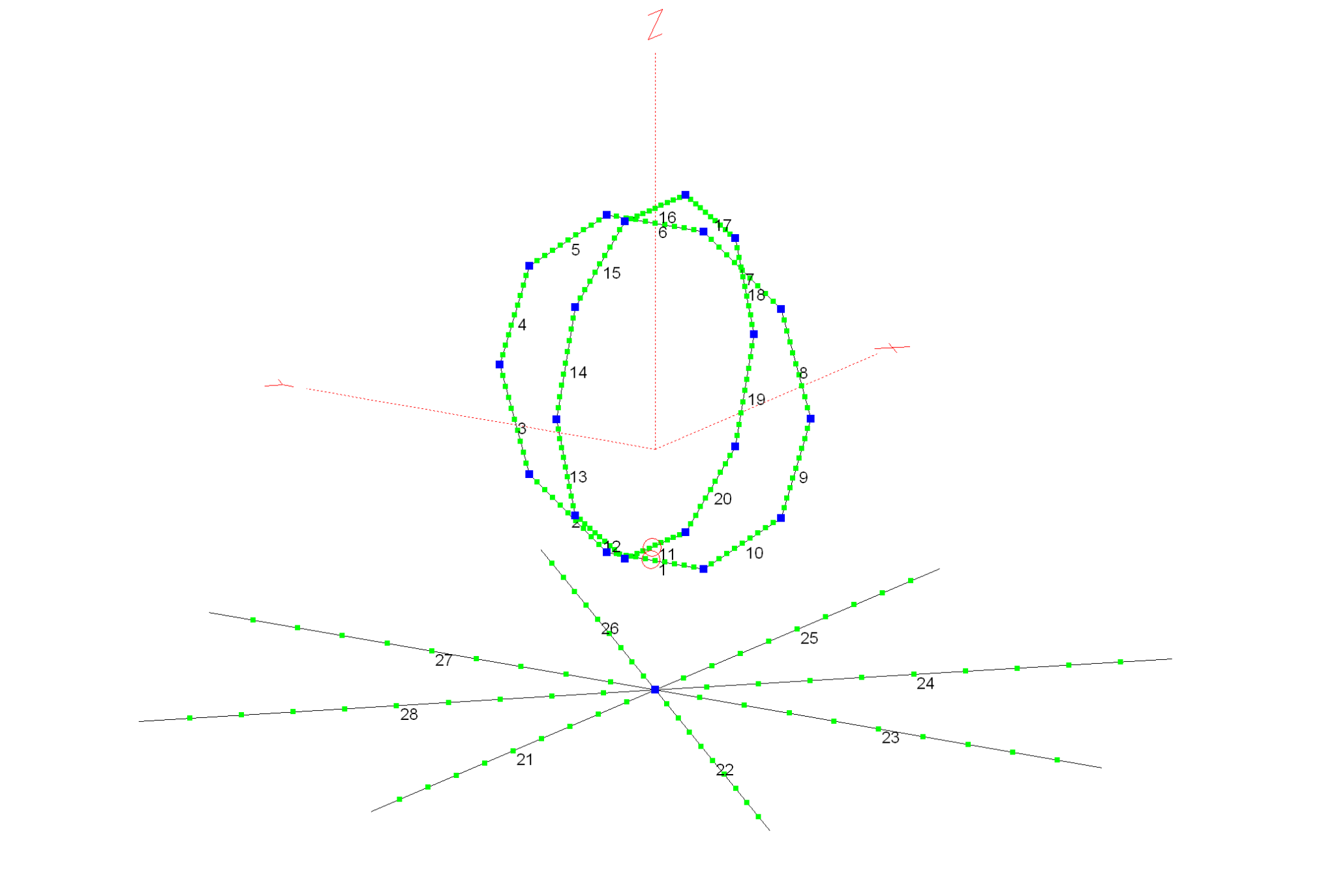
70cm Band Eggbeater Satellite Antenna

Following on from my 2m Band Eggbeater Satellite Antenna here’s the design for the 70cm Band version that will enable duplex satellite operation.

The design is basically the same as the 2m antenna but, with smaller dimensions. All modelling has been done with the antenna at 5m AGL.

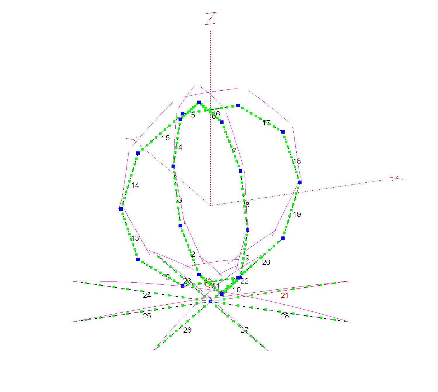
70cm Band Eggbeater Satellite Antenna

Each of the Eggbeater loops has a conductor size of 5mm and a circumference of 73.5cm with the radials exactly 5cm below the bottom of the loops. The 8 radials are exactly 34.15cm long each. The distance between the bottom of the eggbeater loops and the radials must be 5cm to get the best radiation pattern from the antenna.

With these dimensions the antenna has an SWR of <1.5:1 across the whole 70cm band making it ideal for both satellite and general repeater/SSB working.

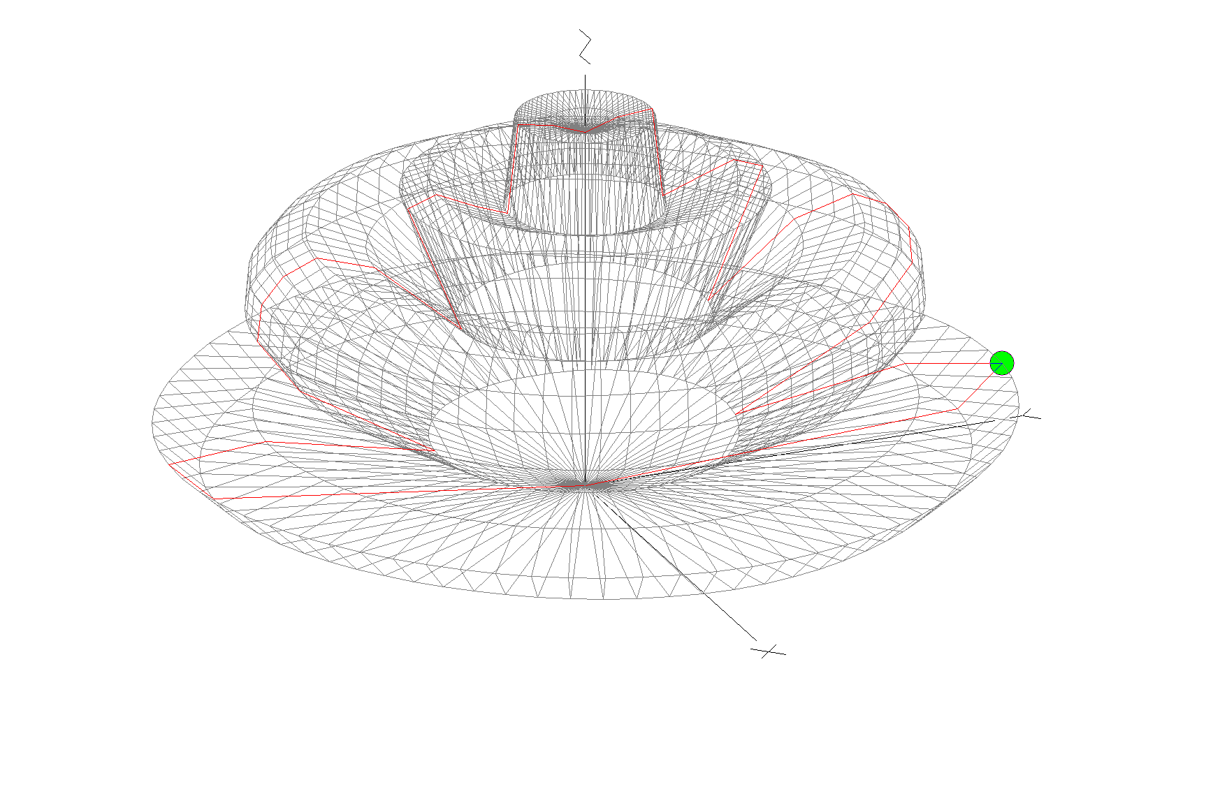
70cm Band Eggbeater Satellite Antenna 3D Far Field Plot

The 3D far field plot shows that the antenna has a good mix of high and low angle radiation that makes it ideal for working satellites at all elevation angles.

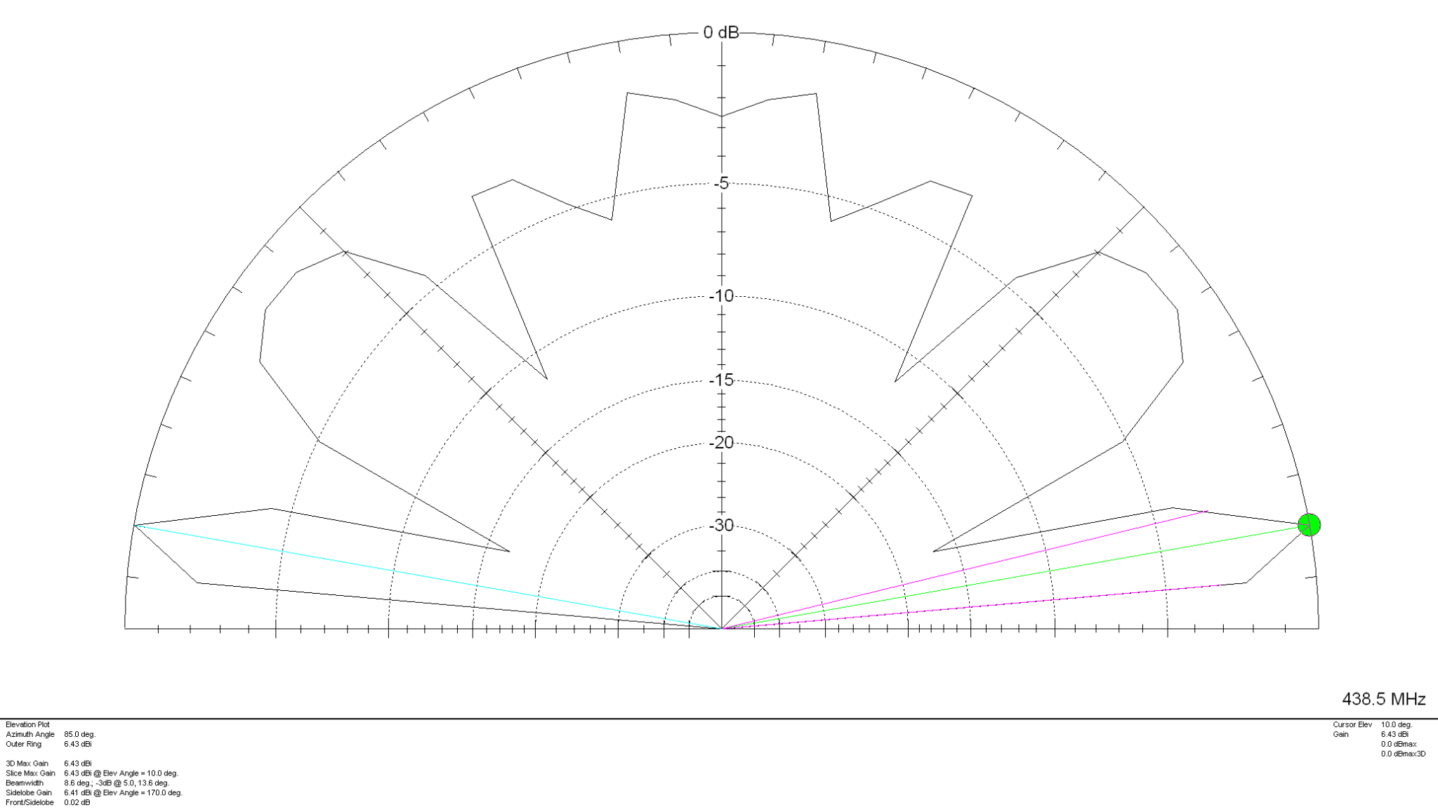
70cm Band Eggbeater Satellite Antenna 2D Far Field Plot

The 2D far field plot shows that the antenna has the following high gain lobes:

6.43dBi @10 Deg
5.15dBi @40 Deg
3.4dBi @60 Deg
4.83dBi @80 Deg

The null at the top of the antenna isn’t as pronounced as on the 2m model and so this antenna should perform better when the satellite is directly above. Just like on the 2m band version, this antenna must also have a feed phase angle of 90 degrees between the two eggbeater elements. It’s very important that the phasing harness is built accurately as it can impact the radiation pattern of the antenna if the phase angle isn’t correct.

ON6WG has written an excellent article on how to create the phasing harness using 2 pieces of coax cable, this is an ideal solution for this antenna.

More soon …

ISS Pass 25/04/24 AM

I had a listen for the ISS FM Repeater this morning using my Dual Band End Fed Vertical Dipole antenna. Not the best antenna for satellite chasing especially since it was a high angle pass this morning however, I did get a relatively good copy on the ISS before it got too high in the sky and fell into the null at the top of the vertical.

A short clip form the ISS pass 25/04/23 AM

I think with an eggbeater antenna reception will improve considerably.

More soon …

2m Band Eggbeater Satellite Antenna

I’ve been chatting a lot recently on Matrix about antennas for the amateur satellites.

Since I’m currently working on building a ground station for the QO-100 satellite a group of satellite enthusiasts having been talking about the other satellites that are in orbit around this little planet of ours.

The ISS FM voice repeater on 145.990Mhz is very popular and is one of the easiest satellite stations to get into apparently. Many are using Eggbeater antennas to get an all round radiation pattern.

I’ve never looked into building or modelling such antennas and so I decided to have a go at modelling one and use it as an opportunity to see how it works.

All the modelling has been done with the antenna at 5m above ground level.

2m Band Eggbeater satellite Antenna with 8 Radials

Each loop has a circumference of 2.17m and each of the 8 radials is 0.5425m long and 5cm below the eggbeater elements. I’ve modelled the antenna using 5mm diameter conductors as this should make them resistant to wind etc. I am planning on using 5mm copper tubing for the build.

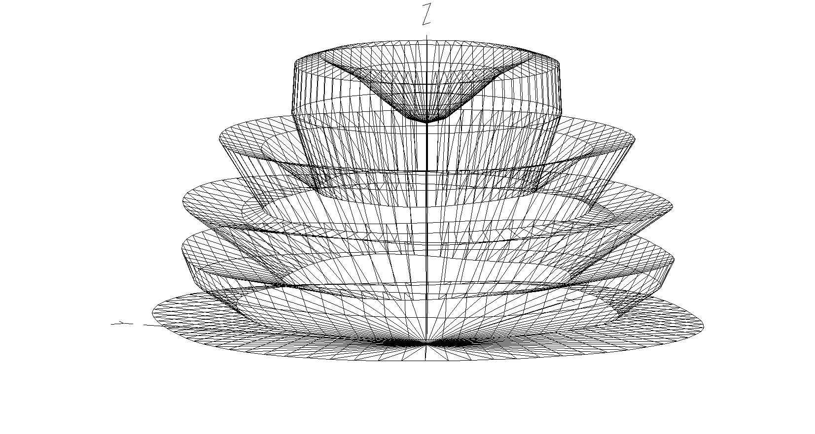
2m Band Eggbeater Satellite Antenna 3D Far Field Plot

The 3D far field plot shows a typical radiation pattern for such an antenna with a very good low angle gain for working satellites on the horizon and multiple high gain lobes as the radiation angle increases. At 5 degrees the RF is horizontally polarised, ideal for shooting directly out at the horizon. This is mainly due to the phasing of the two elements. At the higher angles the RF is vertically polarised thus giving the ability to receive both horizontal, vertical and some circular radiation at a good range of angles. There is however, a very slight null directly above the antenna and so signals to satellites directly above will be attenuated slightly compared to the other two high angle high gain lobes. This will also be the case on receive.

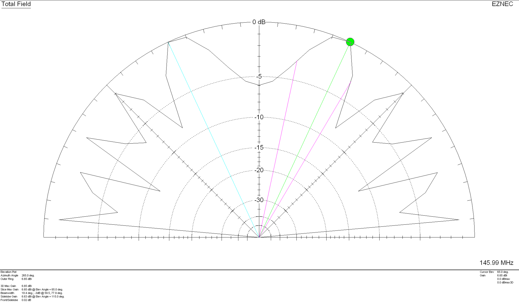
2m Band Eggbeater Satellite Antenna 2D Far Field Elevation Plot

With 5.42dBi gain at 5 Deg this antenna has a real good shot at the horizon with the maximum gain of 6.65dBi being at the much higher angle of 65 Deg. Overall this antenna should work well for all satellites from the horizon up to almost directly above the antenna.

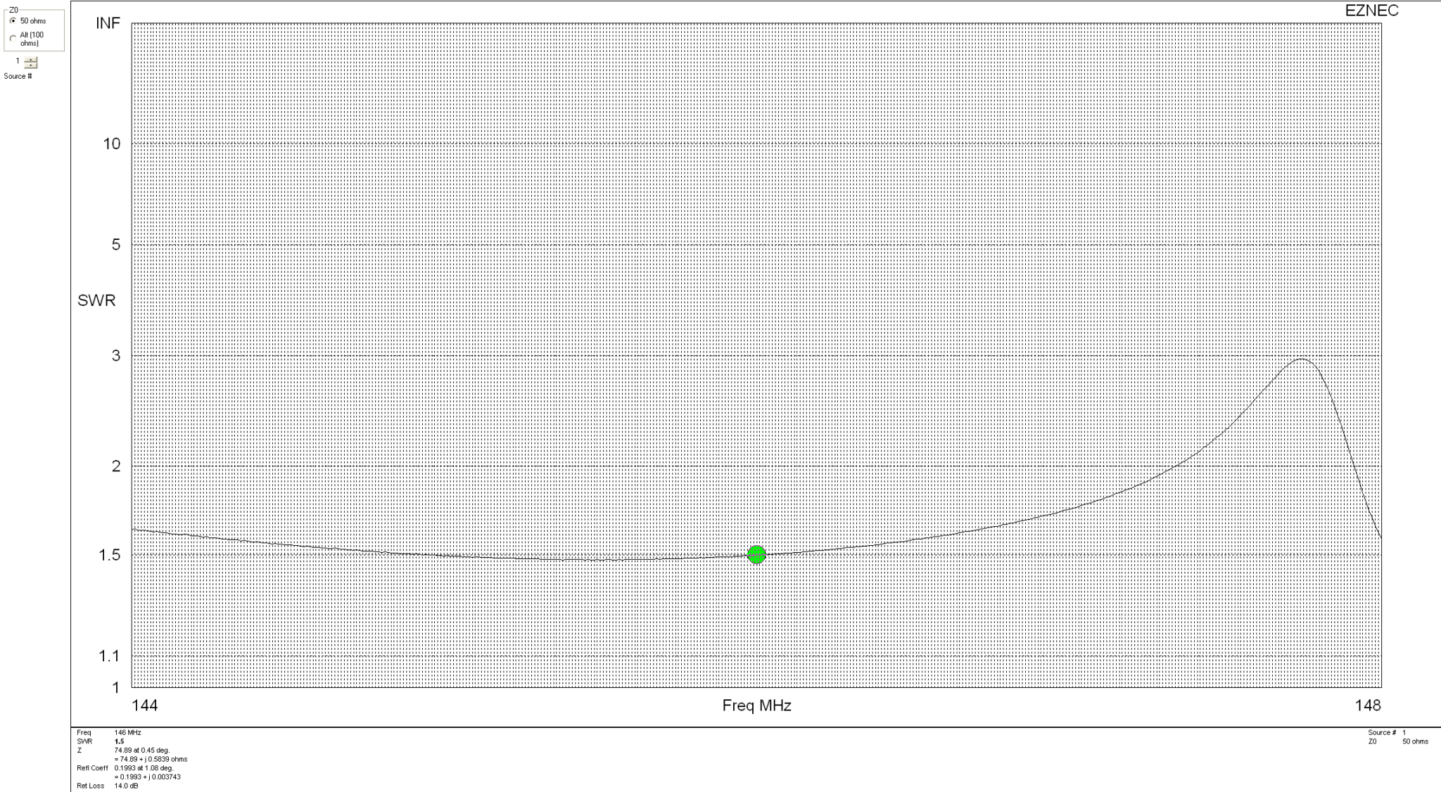
2m Band Eggbeater satellite Antenna SWR Curve

With an SWR of 1.5:1 across most of the 2m band this antenna will match perfectly to 50 Ohm coax feed. It’s really important to remember that when building this antenna the loops must be fed with a phase angle difference of exactly 90 degrees. If this isn’t accurate then the radiation pattern is affected quite drastically and spoils the overall performance of the antenna.

Details on how to create the 90 Degree phase shift between the two elements using 2 pieces of 50 Ohm coax can be found in the excellent article by ON6WG.

More soon …

QO-100 TX/RX Dashboard

I’ve now completed the GQRX Receive and Icom IC-705 Transmit dashboard in Node Red. It was a fun project to put together and needed some javascript coding to get the functionality I wanted but, I got there in the end.

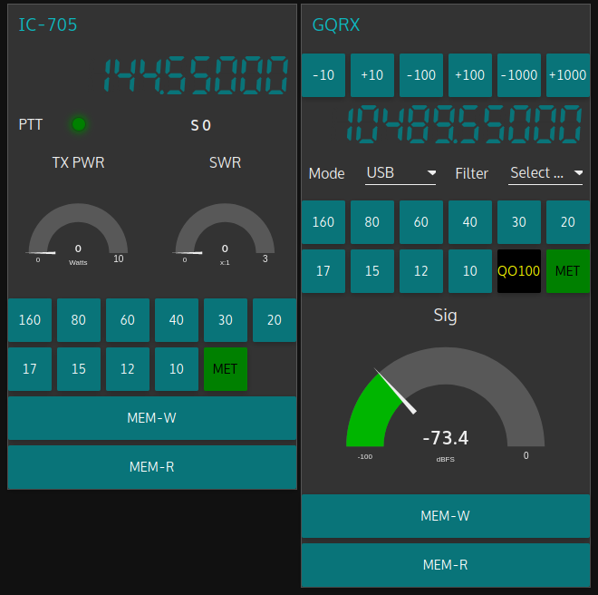
M0AWS QO-100 GQRX/IC-705 control dashboard

The dashboard looks fairly simple but, there is a lot behind the scenes to get it to this stage.

On the left is the Icom IC-705 transmit control panel. It shows the transmit frequency, power output and SWR reading. The SWR is so that I can check that the input into the 2.4Ghz transverter doesn’t have any connectivity issues. The “S0” will actually display the S Meter reading when the IC-705 is being used as a normal transceiver rather than being in QO-100 Duplex mode as shown above where the GQRX app and Funcube Dongle SDR are being used as the receiver.

The GQRX side of the dashboard shows the downlink frequency which tracks the uplink frequency of the VFO on the IC-705. This will ensure that the Funcube Dongle Pro+ SDR receiver will always be on the correct downlink frequency relative to the uplink frequency, thus I should always be able to hear my own signal coming from the QO-100 satellite.

Once taken out of QO-100 mode the two radios can be used independently on any of the HAM bands and can be switched using the buttons on the dashboard.

I also coded in a simple memory facility where a frequency can be stored in Node Red and recalled later on both the transmit and receive sides.

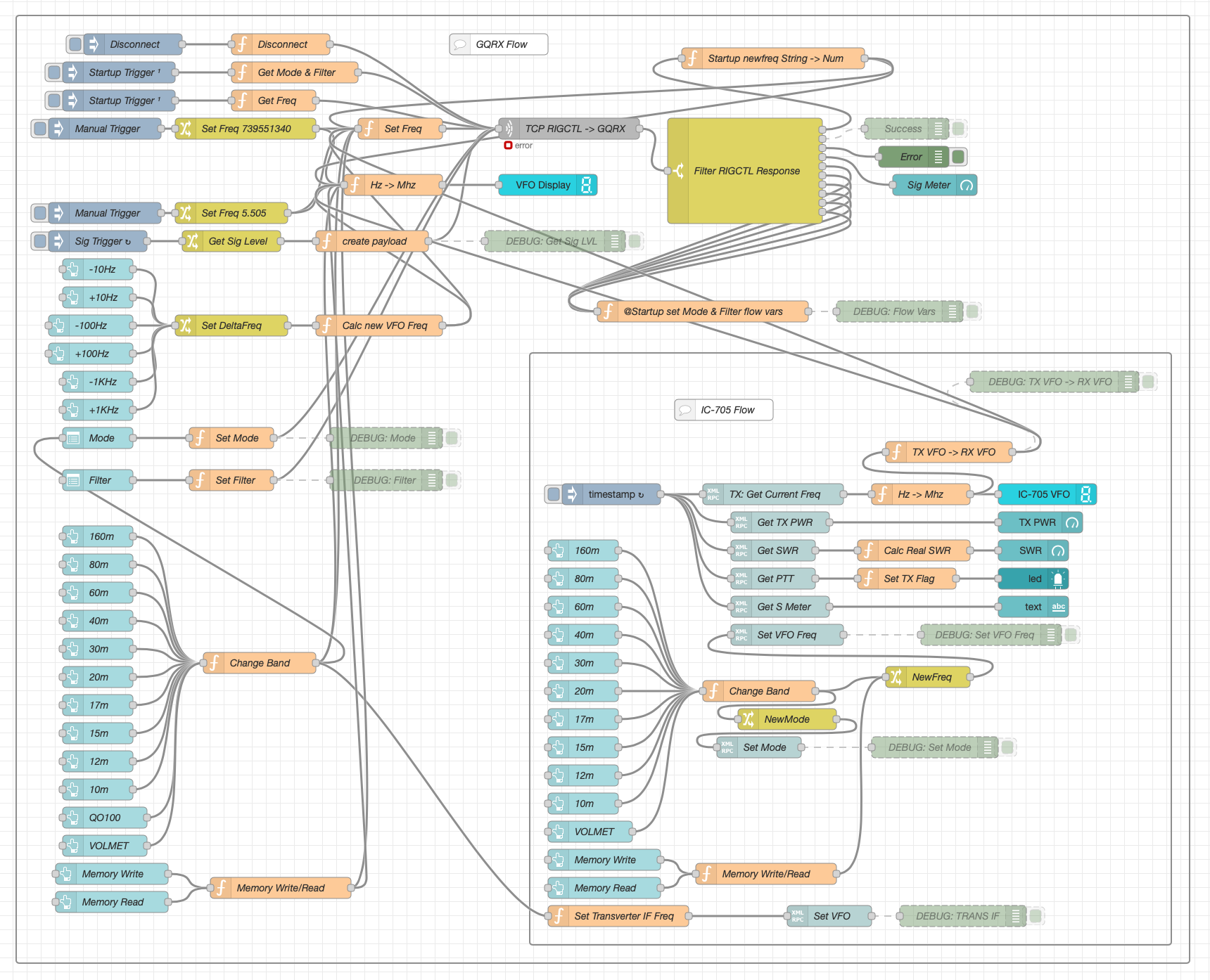
Looking at the dashboard it all looks simple and straight forward however, if you look at the Node Red flow it becomes obvious that this isn’t the case.

QO-100 Dashboard Flow in the Node Red Editor (Click for larger image)

There’s a lot to the flow to get the information from the receiver and transmitter so that it can be presented on the dashboard. There’s also some code to convert between Rigctl protocol used by the GQRX application and XMLRPC used by the IC-705 via FLRig and WFview. I had to also code around a bug in the Node Red XMLRPC node whereby you have to add 0.1 onto the VFO frequency for it to be passed onto the radio otherwise the information is never sent. This was a real pain of a bug to find but, with a little experimentation I found the problem and managed to code around it. The strange thing about this is that the 0.1 added onto the frequency isn’t actually passed onto the radio via the XMLRPC node, it just has to have that on input otherwise it doesn’t work at all. A very strange bug and hopefully one that will be fixed by the node developer in future releases.

All that is left to do now is add the temperature sensors dashboard to complete the dashboard. These haven’t arrived yet and so I’ve not been able to create the necessary flow to collect the data from them.

Hopefully this coming week the weather will improve and I’ll start getting the dish antenna up and the get the receive side working.

UPDATE: Further development of my QO-100 Dashboard has taken place, you can read all about it here.

More soon …

QO-100 Satellite Node Red Dashboard

Whilst I’ve been waiting for the weather to improve so that I can get my QO-100 dish antenna up I’ve been working on my QO-100 Node Red dashboard.

The idea of the dash board is to bring together the operating of the receiver and transmitter into one control centre so that the two separate devices are able to communicate and behave as if they were actually one device, like a transceiver rather than being individual components.

Ideally I would like to have the transmitter and receiver talking to each other such that when the VFO on the transmitter is incremented/decremented the receiver VFO also moves by the same amount.

By doing this the receiver VFO should always be in the right place on the 10Ghz band to hear my 2.4Ghz uplink signal and of course, any station coming back to my CQ calls.

So far I’ve only been working on the receive part of the Node Red flow, it’s certainly been a lot of fun getting it put together.

I control my Funcube Dongle Pro+ (FCD) using GQRX SDR on my Kubuntu PC. This software is working extremely well with the FCD and I’m happy with the level of functionality it offers.

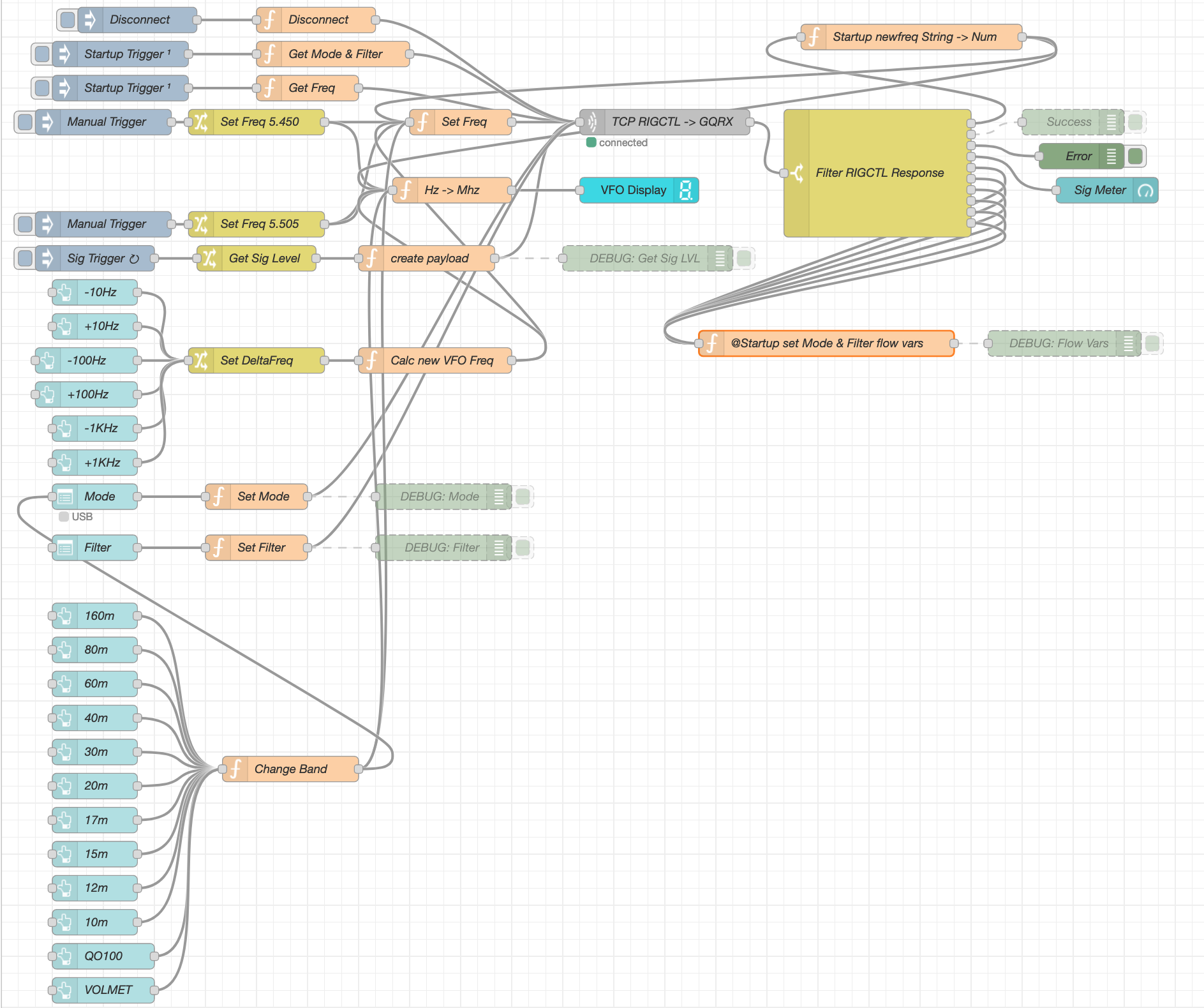
GQRX SDR has the ability built in to control the SDR via remote TCP connection using RIGCTL protocol. Currently there isn’t a RIGCTL node available for Node Red so I have written a number of Javascript function nodes that provide the appropriate functionality in conjunction with a standard Node Red TCP node. This is working extremely well on the local LAN in the radio room and is proving to be very stable and responsive.

M0AWS QO-100 Node Red Flow – Receive Section

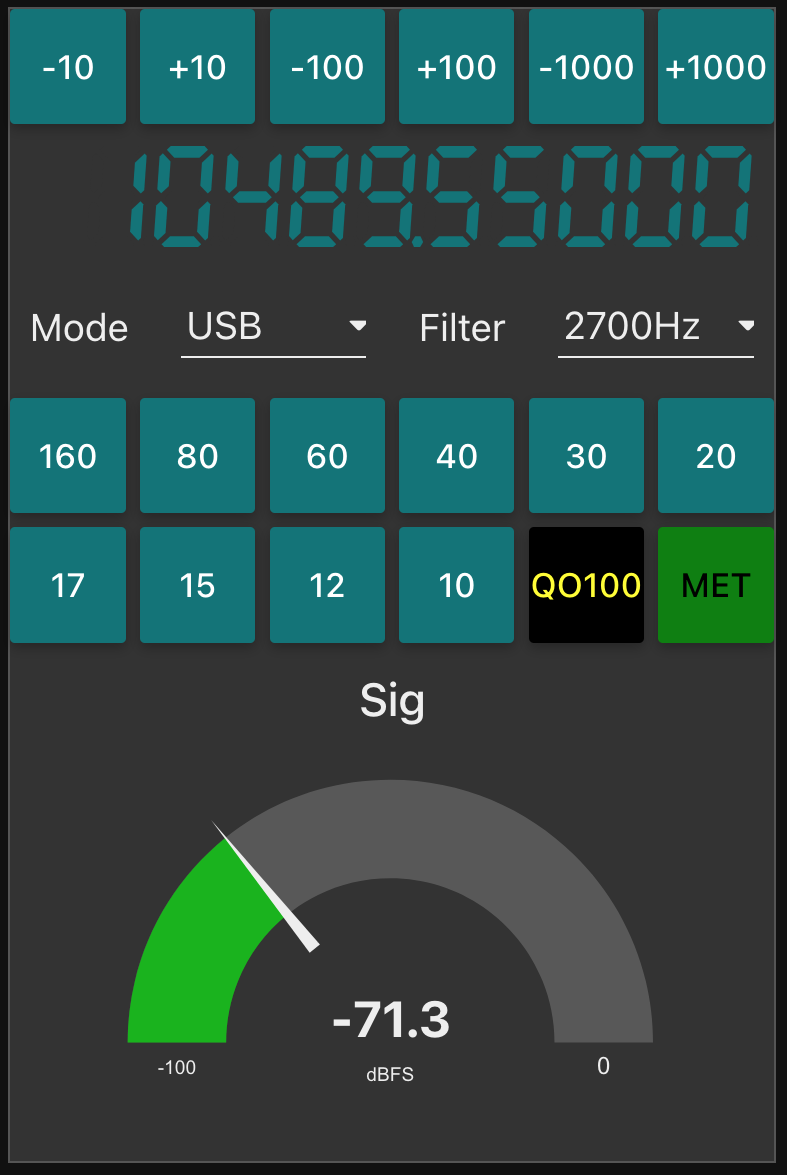
The flow for the receive section of the dashboard looks fairly complicated but, in reality it’s really not too difficult to get to grips with. The receive flow provides the facility to switch bands, switch modes, change receiver filter band width, display a realtime signal strength meter, receive +/- clarifier in 10/100/1000Hz increments and put the receiver into QO-100 mode where the SDR VFO is tuned to 739.550Mhz whilst the dashboard VFO shows the QO-100 downlink frequency in the 10Ghz band. This is all working very well and I’m happy with the initial result.

M0AWS QO-100 Receive Dashboard in QO-100 mode

I now need to start work on the transmit side of the QO-100 dashboard and get communications between my IC-705 transceiver and the FCD SDR working via Node Red. This could be a little more challenging as it will involve communicating with the IC-705 via WFView over wifi.

More soon …

QO-100 Station – Initial parts purchase

After much reading and viewing of youtube videos I have finally settled on the parts that I want to use to build my QO-100 Satellite ground station.

Initially I’m only going to build the receive path of the QO-100 station. From the articles and blogs I’ve read online all the experienced Amateur Radio satellite Op’s recommend getting the receive side sorted first and then moving onto the transmit path.

I need to stress here that I have no experience of radio above 433Mhz (70cm), a band that I have only used a handful of times. 99% of my Amateur Radio life has been spent below 30Mhz and so this is going to be a very new experience for me.

So, what am I going to purchase for the receive path?

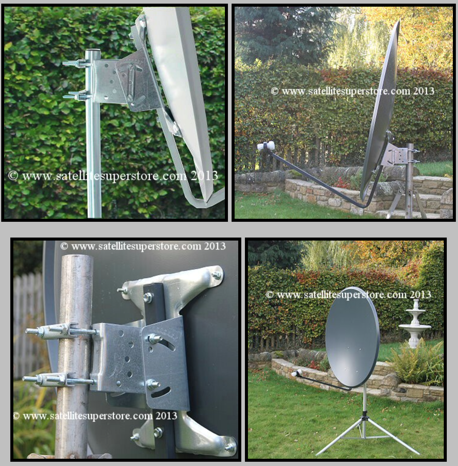
I’ve settled on a 1.1m off-set dish from the Satellite Super Store that should give me plenty of gain if I manage to get it pointed successfully at the bird.

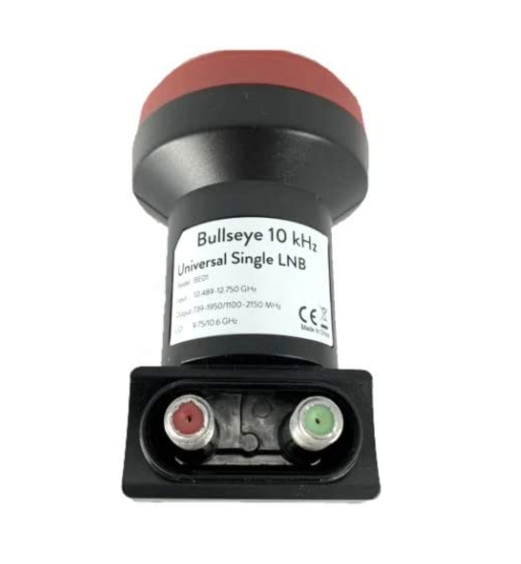
I’ll pair a Bullseye 10Ghz TCXO LNB with the dish to give me a high stability receive path that shouldn’t wander too much up and down the band with temperature changes throughout the seasons.

1.1m Off-Set Dish for QO-100

The Bullseye LNB gets extremely good reviews from the HAM Satellite community, although it is a little on the expensive side compared to many others available. Since I only want to do this once I’ve gone with the more expensive option in the hope that it gives me the stability I’m looking for.

Since we’ve never had satellite TV here at home I’ve only just learnt that LNBs require a voltage feed since reading about other peoples QO-100 station builds. Most LNBs can be used for either horizontal or vertical polarisation and are switched by feeding with either 12v or 18v respectively. The LNBs also use this same voltage feed to do the frequency down conversation and some amplification of the received signal.

At the moment I’m only looking to get onto the narrowband part of the QO-100 satellite service and so I will need to feed the LNB with around 12v to ensure vertical polarisation is achieved. The easiest way to do this is to inject the 12v feed up the coax cable to the LNB.

Bullseye 10Ghz TCXO LNB

To achieve this I will need to purchase a little circuit called a Bias Tee. This relatively simple circuit consists of a capacitor and inductor combination that stops the 12v from going back into the receiver whilst at the same time stopping the RF from going back into the power supply.

Bias Tee units are relatively cheap to buy online and I have decided to get one from Amazon that has been recommended in a number of blogs posts I have read during my research.

Broco Bias Tee

With these parts ordered I now need to source the materials to mount the dish up above head height in the garden with a clear view of the sky in the direction of the satellite.

Getting the dish up high enough to be above head height will be important for when I get the 2.4Ghz uplink path in place. At these frequencies it’s important to ensure that no one is able to walk across the front of the dish whilst I’m transmitting. I’m hoping to get the dish up about 3m in the air in such a fashion that it is rigid enough to stop the dish moving around in the wind. I must admit I’ve not done any wind load calculations for the 1.1m dish so I’ll have to see how it goes over time. Fortunately where I want to put the dish is fairly well sheltered from the north wind that often howls through here so, hopefully it won’t be an issue.

More soon …

Funcube Dongle Pro+ / GQRX / Kubuntu

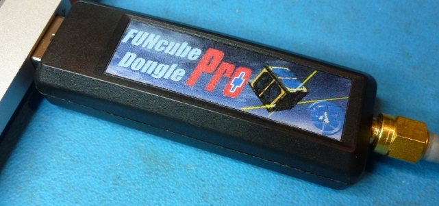
Many years ago I purchased a Funcube Dongle Pro+ (FCD) SDR. Since it’s arrival it has just been stored in my “Get round too it” drawer.

It’s been many years but, today is the day it comes out into the light and finally gets powered up.

Funcube Dongle Pro+ USB SDR

I’m hoping to be able to use the FCD as the receiver in my QO-100 satellite ground station setup.

The output from the 10Ghz dish mounted LNB is around 739Mhz, well within the FCD receiver range of 150khz to 2Ghz. This will save me from having to transvert from 739Mhz to 430Mhz (70cm band) on the receive path.

This will also give me full duplex operation as I will use my Icom IC-705 on the 2m band (144-146Mhz) to drive the 2.4Ghz transverter for the satellite uplink whilst listening to my own signal via the 10Ghz downlink fed into the FCD.

Before I can even start to build the QO-100 satellite ground station I need to get to grips with the FCD, get the software installed, configured, resolve audio routing via virtual audio cables and get it decoding FT8/JS8/WSPR etc.

Talking to G0DUB in the General Amateur Radio Chat room on Matrix he recommended trying the GQRX software to drive the FCD. GQRX is open source which fits perfectly as I want to control the FCD from my Kubuntu PC.

Checking the Ubuntu repo’s I found that GQRX v2.12 is available for installation.

sudo apt install gqrx-sdr

Once installed I fired up GQRX and set about configuring it. Initially it appeared to have automatically detected and configured the FCD however, when I started the FCD the software ran for 5 seconds and then just hung.

Diving into the configuration settings I found that the FCD actually appears twice in the list of available devices and all I had to do was select the other one in the list and start the software again and all was well.

I connected my 20m Band EFHW Vertical antenna and trawled up and down the band. The receiver performed well even with fairly strong signals so, I spent some time listening to a few of the stations coming in from the USA.

Next I wanted to sort out the configuration for digital modes. I already have a couple of virtual audio cables in the form of loopback audio devices configured on my Kubuntu PC as this is how I connect the audio between WFView for the IC-705 and WSJT-X/JS8CALL.

Sadly, GQRX doesn’t recognise the loopback audio devices that already exist and so I had to do a little further research to get to the bottom of the issue.

Digging deeper I discovered that GQRX requires loopback audio devices created using Pulse Audio and not the kind I had already created at the O/S level. A quick read of the pactl man page and some further searching online I found all the info I needed to create the correct kind of loopback audio devices.

Two commands are required to create the pulse audio server audio loopback devices:

pactl load-module module-null-sink sink_name=gq2jt sink_properties=device.description="gq2jt"

pactl load-module module-loopback latency_msec=1

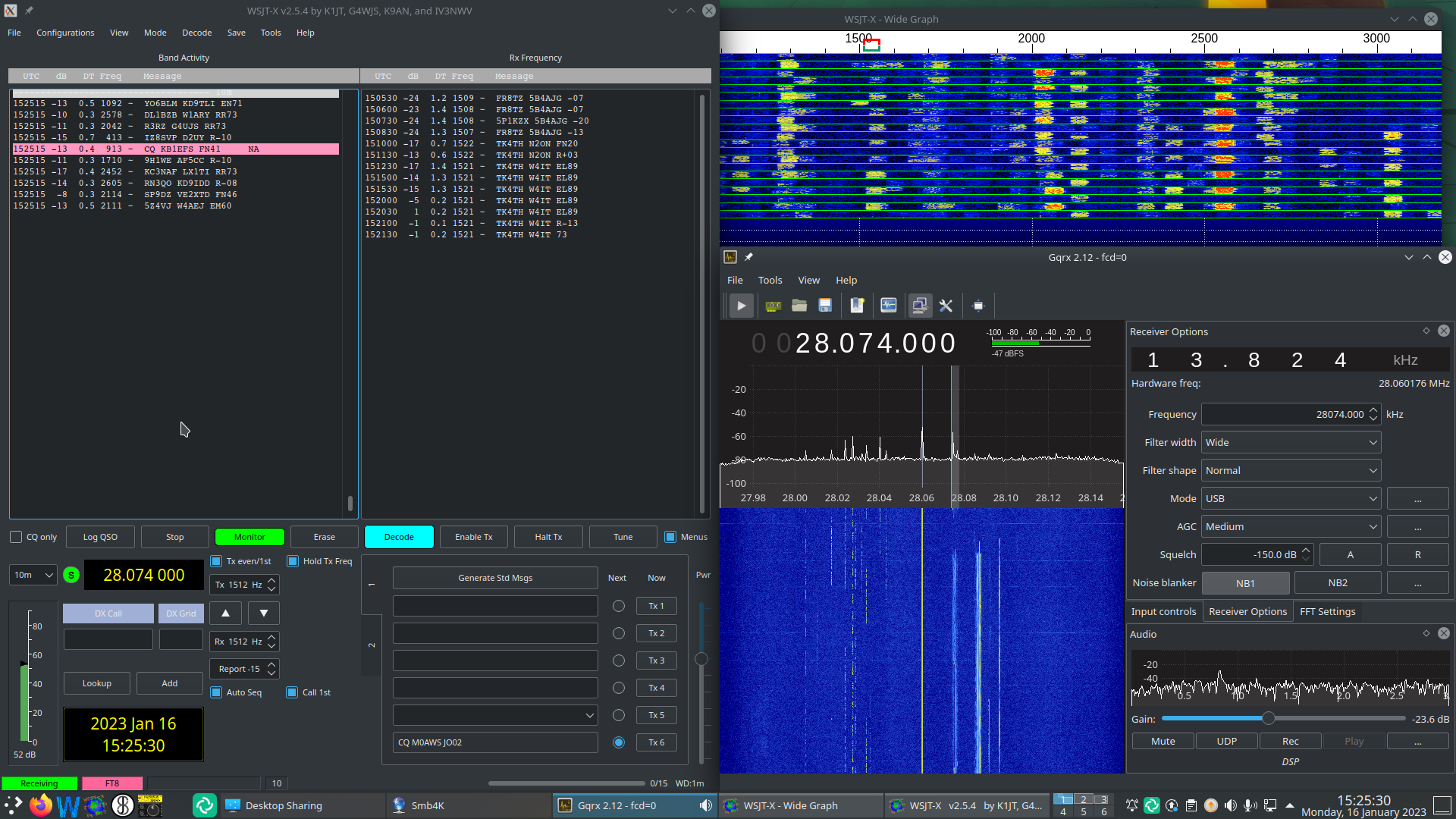
Once I’d created the loopback audio devices I was able to select the gq2jt devices in both GQRX and WSJT-X/JS8CALL so that the audio was routed correctly.

GQRX SDR and WSJT-X working with the Funcube Dongle Pro+

The overall solution works well and doesn’t put much load on the CPU of my Kubuntu PC, leaving plenty of horse power for me to do other things at the same time.

So I now have the Funcube Dongle Pro+ working perfectly on my Kubuntu PC, all I need now is a 1.2m dish, a 10Ghz LNB and some high quality coax cable.

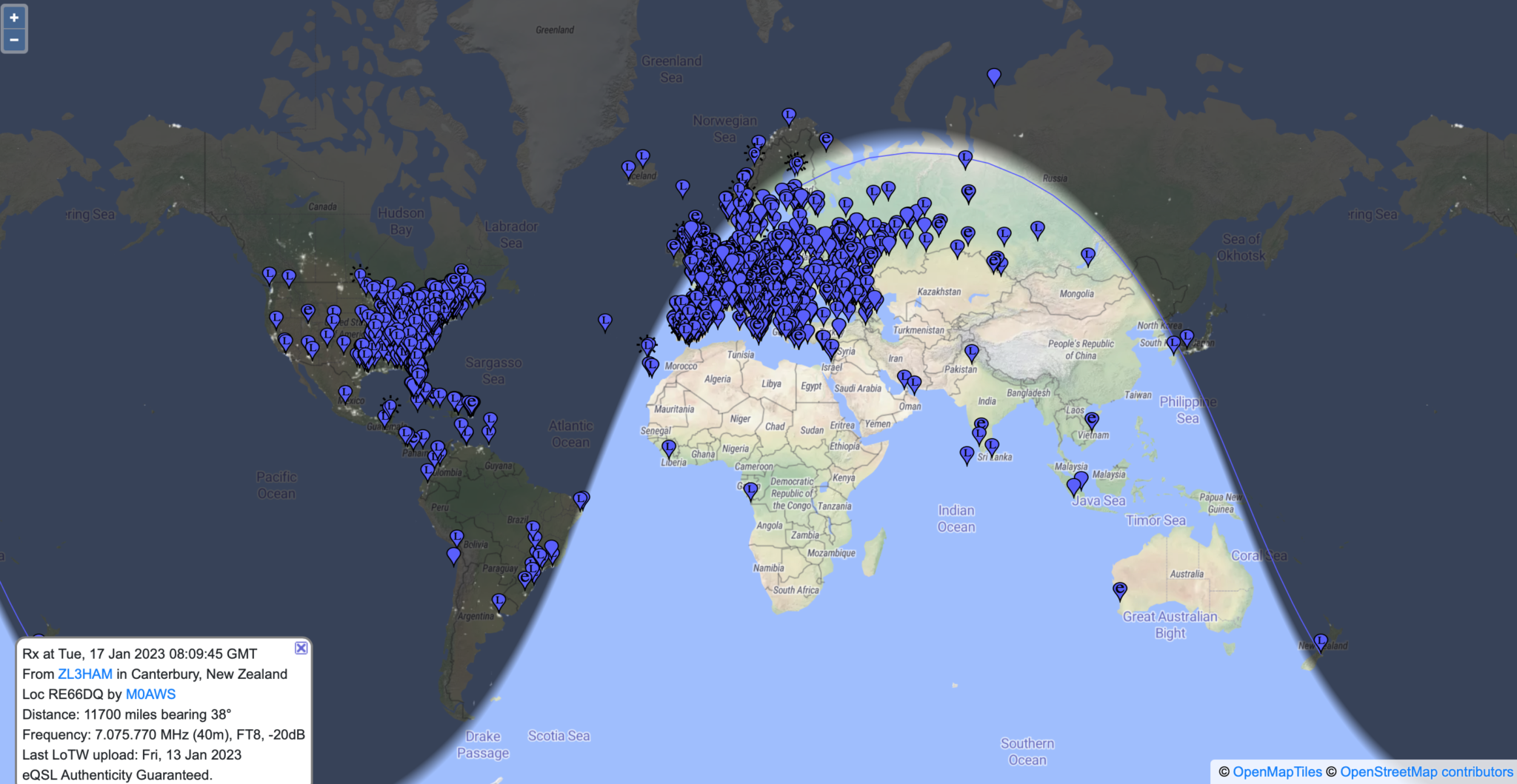
UPDATE: I decided to leave the FCD connected to the 20m Band EFHW Vertical overnight and monitor FT8 on the 40m band. The EFHW antenna isn’t anywhere near resonant on the 40m band and so I thought it would be interesting to see how well the FCD performed on a completely non-resonant antenna.

To my surprise it did exceptionally well, stations from all over the world were heard with ease, the FCD really is an excellent little SDR receiver.

Map showing stations heard on 40m Band FT8 over night 16/17 Jan 2023

If you’re looking for a relatively cheap but, effective receiver for FT8/WSPR monitoring then I can highly recommend the FCD. If paired with a RaspberryPi then it would be a really cheap to purchase/operate solution for any HAM operator or short wave listener (SWL).

More soon …