QO-100 Satellite Ground Station Complete Build

I get quite a few emails from readers of my blog asking how my QO-100 satellite station is put together and so, I thought perhaps now is a good time to put together an article detailing the complete build.

My QO-100 satellite ground station is built around my little Icom IC-705 QRP transceiver, it’s a great little rig and is ideal for the purpose of driving a 2.4Ghz transverter/up-converter.

Of course all the software used for the project is Opensource and freely available on the internet.
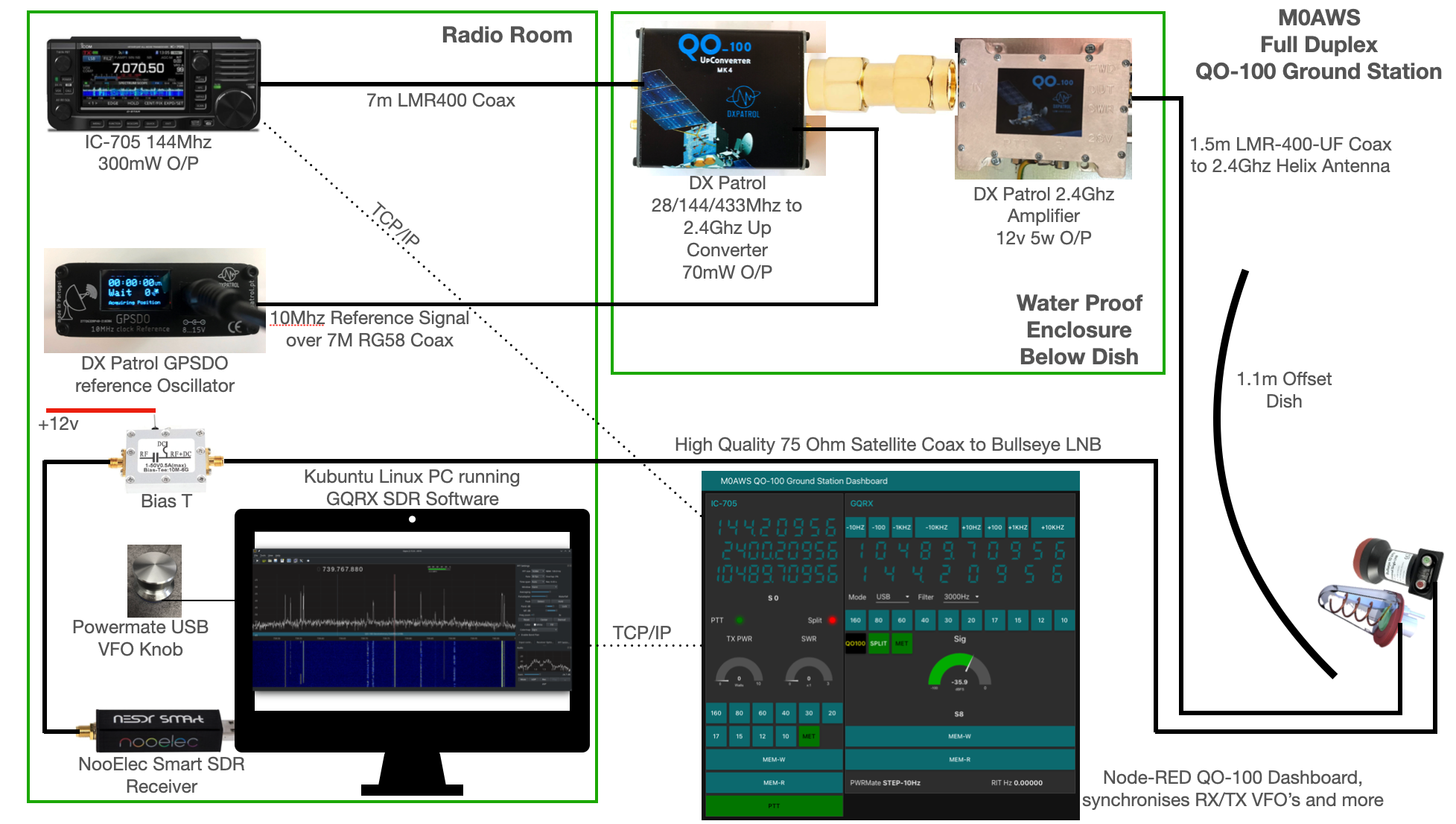
M0AWS QO-100 Ground Station Build Visual
M0AWS QO-100 Ground Station Build Visual (Click to Enlarge)

The station comprises of the following building blocks:

  • Icom IC-705 Transceiver
  • DXPatrol 28/144/433Mhz to 2.4Ghz Up-Converter
  • DXPatrol GPSDO Reference Oscillator
  • DXPatrol 2.4Ghz 5/12w Amplifier
  • Nolle Engineering 2.2 turn 2.4Ghz IceCone Helix Antenna
  • 1.1m (110cm) Off-set Dish
  • Bullseye 10Ghz LNB
  • Bias-T to feed 12v to LNB
  • NooElec SmartSDR Receiver
  • PC Running Kubuntu Linux Operating System
  • GQRX SDR Opensource Software
  • Griffin Powermate USB VFO Knob
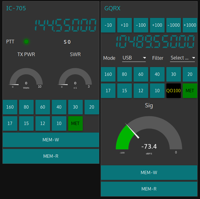
  • QO-100 Ground Station Dashboard developed using Node-RED
  • LMR400-UF/RG58 Coax Cable
M0AWS QO-100 1.1m off-set Dish and IceCone Helix antenna ground station
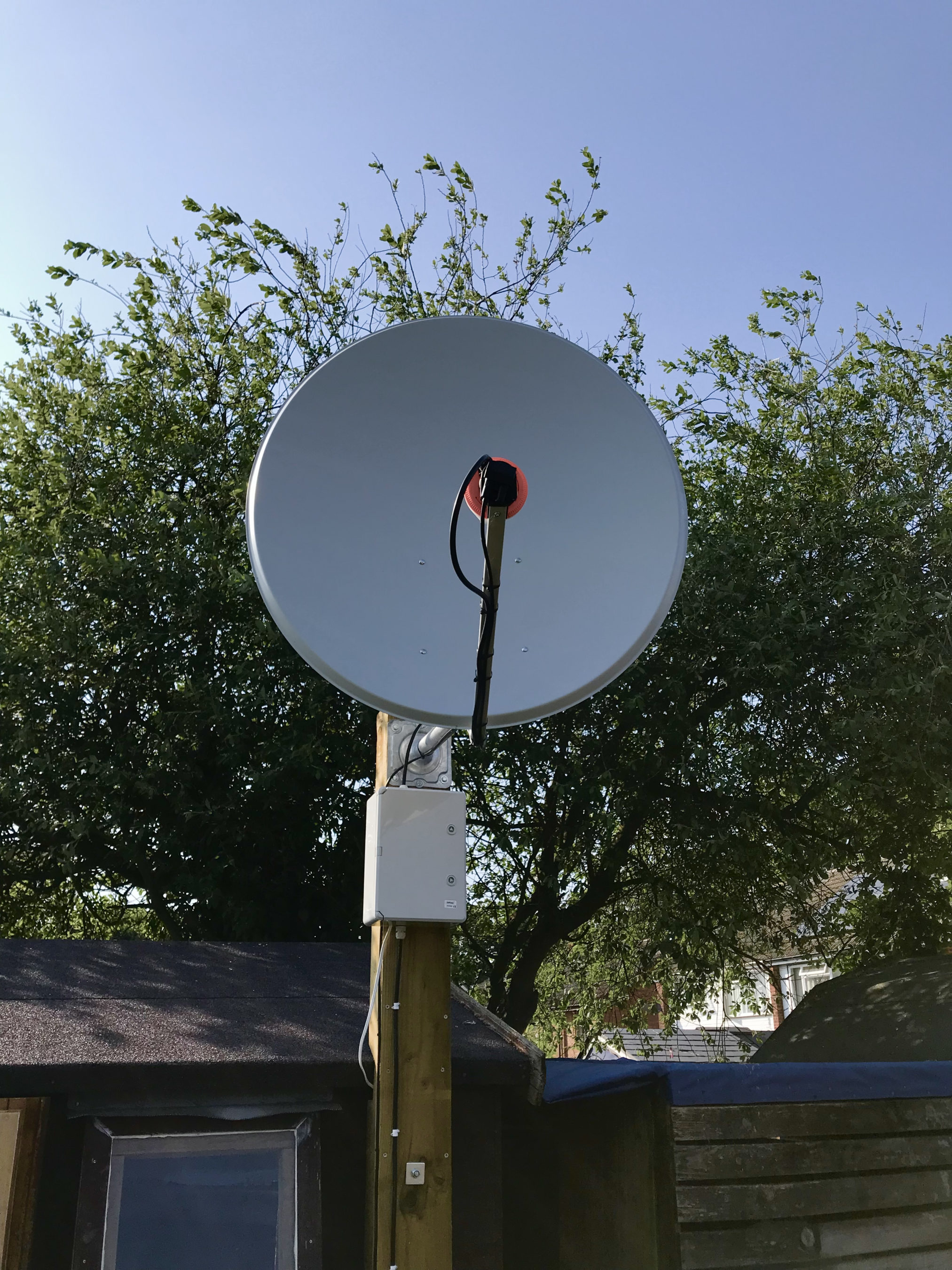
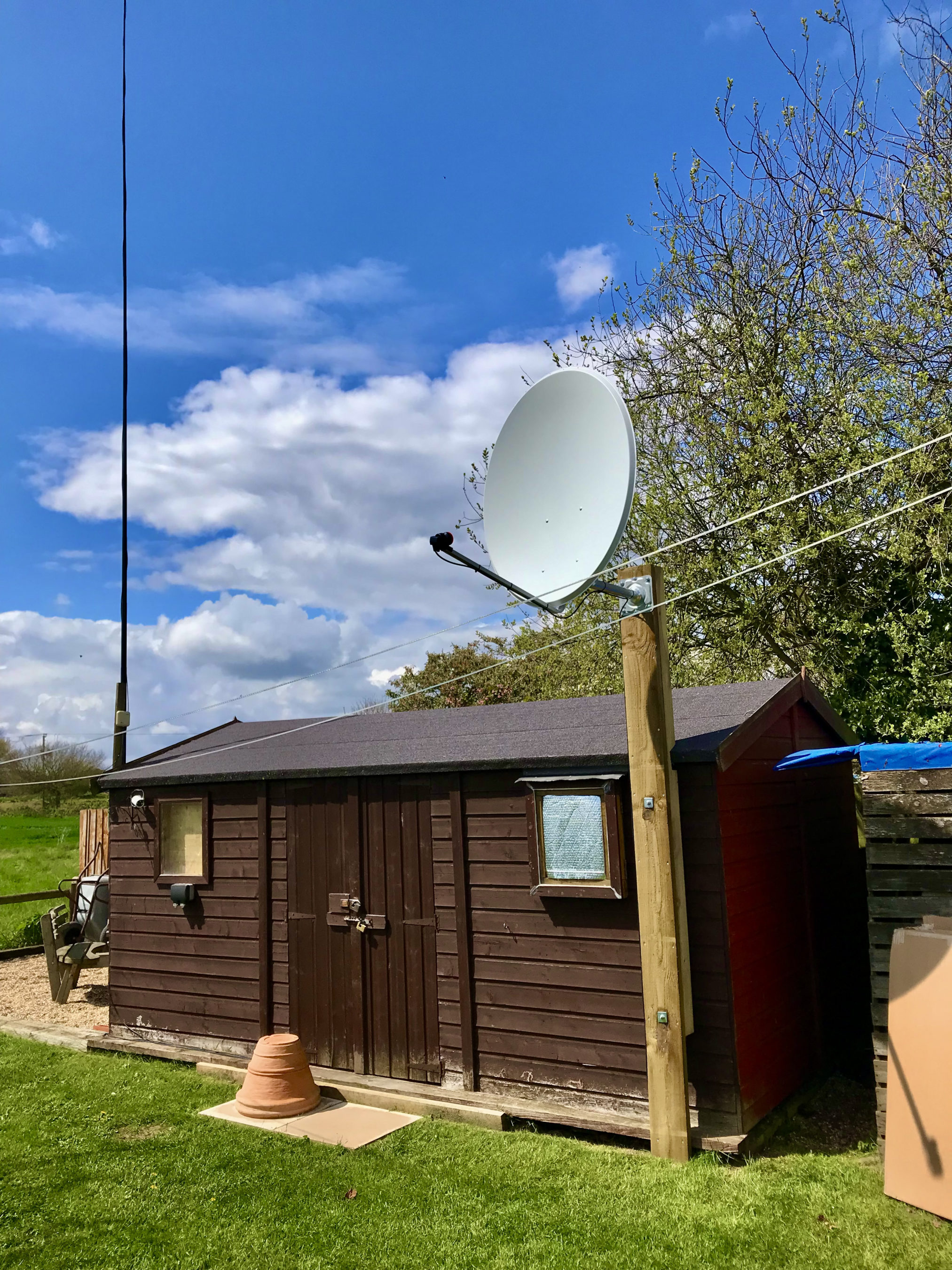
M0AWS QO-100 1.1m (110cm) off-set Dish with IceCone Helix antenna and Bullseye LNB.

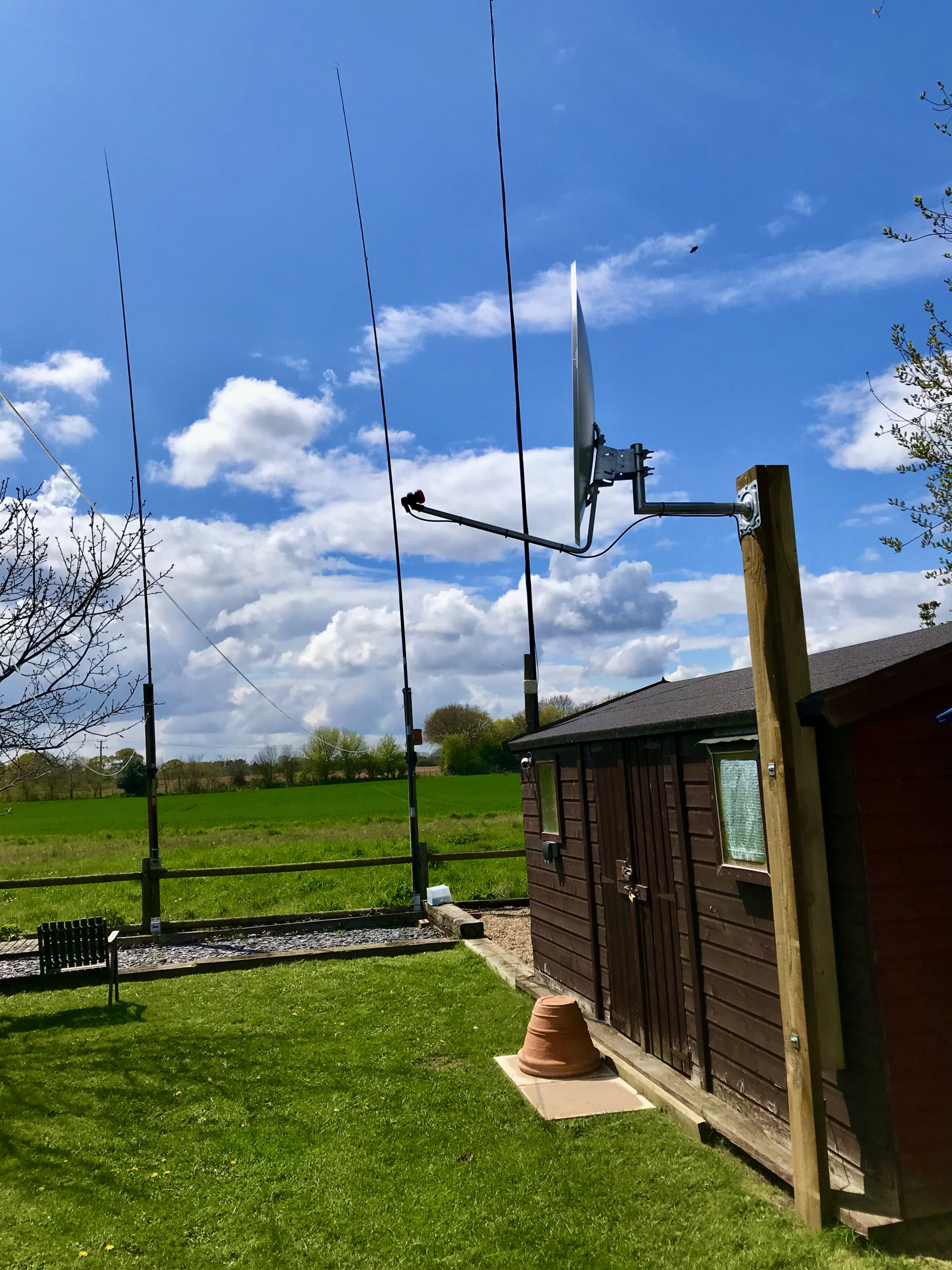
To get a good clear view of the QO-100 satellite I have the dish mount 3.2m above the ground. This keeps it well clear of anyone walking past in the garden and beams the signal up at an angle of 26.2 degrees keeping well clear of neighbouring gardens.

The waterproof enclosure below the dish houses all the 2.4Ghz equipment so that the distance between the feed point and the amplifier are kept to a minimum.

The DXPatrol amplifier is spec’d to run at 28v/12w or 12v/5w, I found that running it at 28v produced too much output for the satellite and would cause the LEILA alarm on the satellite to trip constantly. Running the amp at 12v with a maximum of 5w output (average 2.5-3.5w) is more than enough for me to have a 5/9+10 signal on the transponder.

The large 1.1m dish gives me quite an advantage on receive enabling me to hear the very weak stations with ease compared to other stations.
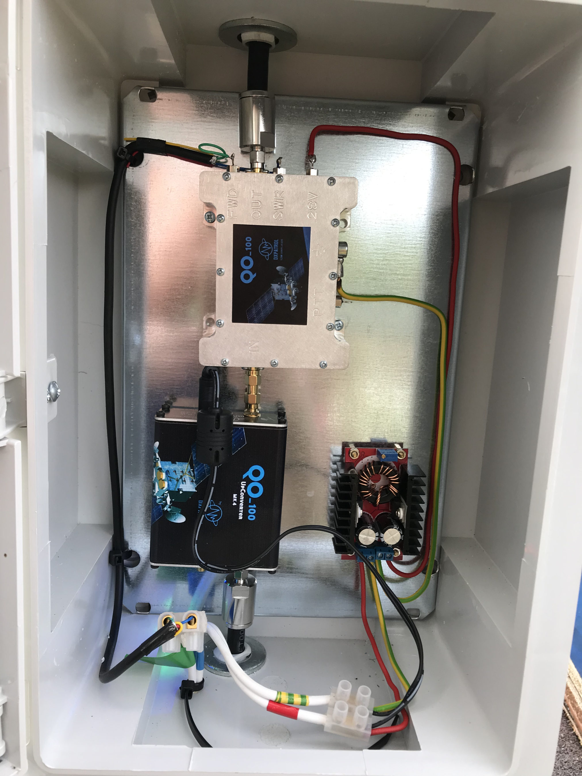
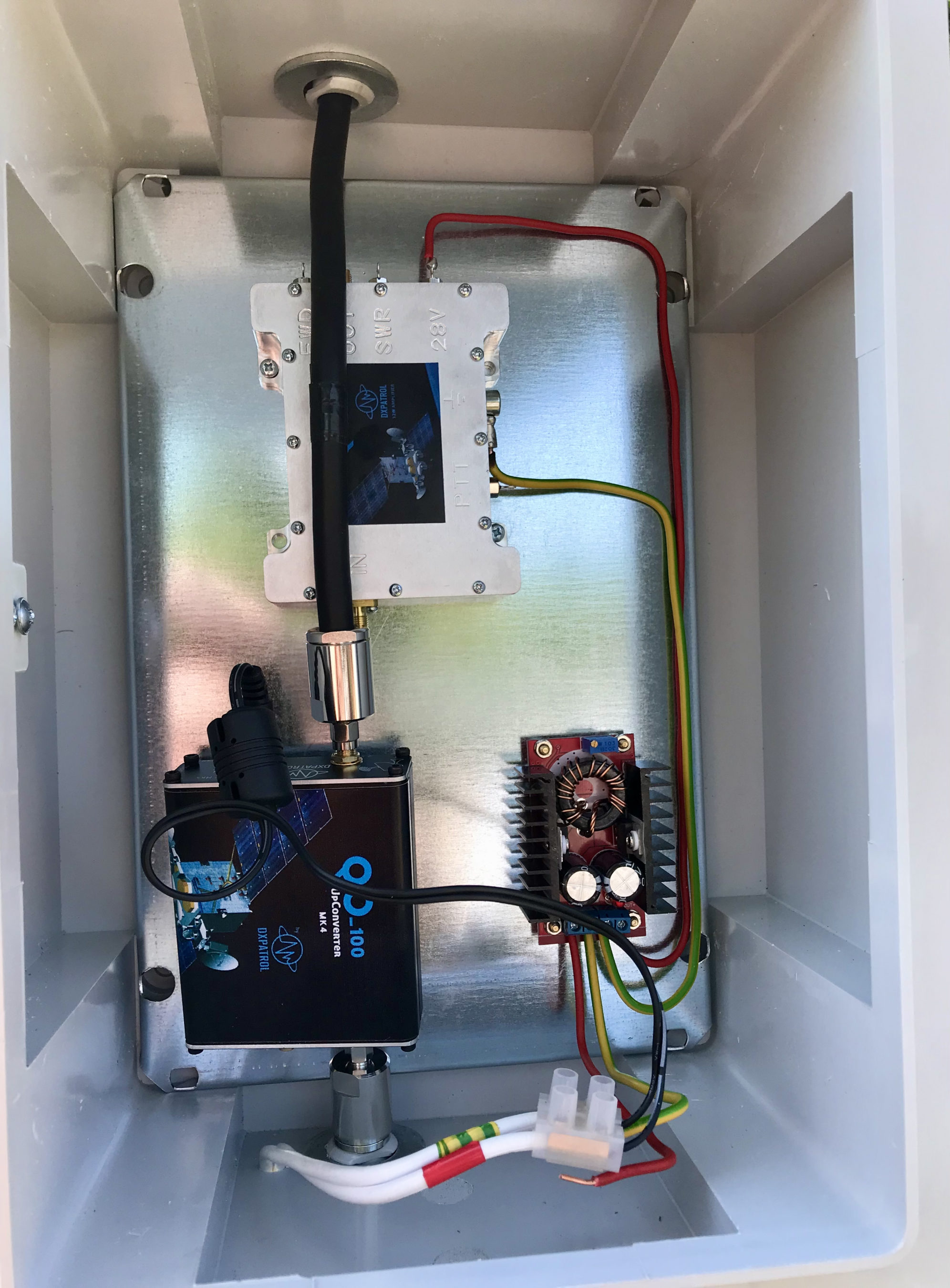
2.4Ghz ground station enclosure ready for testing

The photo above shows the 2.4Ghz equipment mounted in the waterproof enclosure below the dish. This photo was taken during the initial build phase before I rewired it so, the amplifier is shown connected to the 28v feed. To rewire the amp to 12v was just a matter of removing the 28v converter and connecting the amp directly to the 12v feed instead. This reduced the output from a maximum of 12w down to a maximum of 5w giving a much better (considerate) level on the satellite.

It’s important to keep all interconnects as short as possible as at 2.4Ghz it is very easy to build up a lot of loss between devices.

For the connection from the IC-705 to the 2.4Ghz Up-Converter I used a 7m run of
LMR-400 coax cable. The IC-705 is set to put out just 300mW on 144Mhz up to the 2.4Ghz converter and so it’s important to use a good quality coax cable.

Once again the output from the 2.4Ghz amplifier uses 1.5m of LMR-400-UF coax cable to feed up to the 2.2 turn Icecone Helix Antenna mounted on the dish. This keeps loss to a minimum and is well worth the investment.
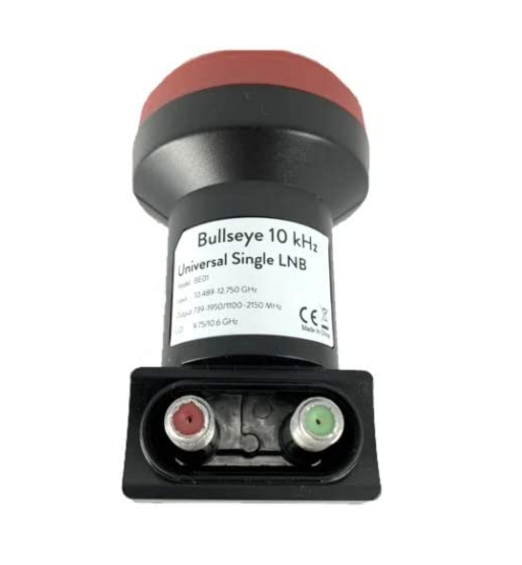
Bullseye 10Khz High Stability Unversal Single LNB for 10.489-12.750Ghz

The receive path starts with a Bullseye LNB, this is a high gain LNB that is probably one of the best you could use for QO-100 operations. It’s fairly stable frequency wise but, does drift a little in the summer months with the high temperature changes but, overall it really is a very good LNB.

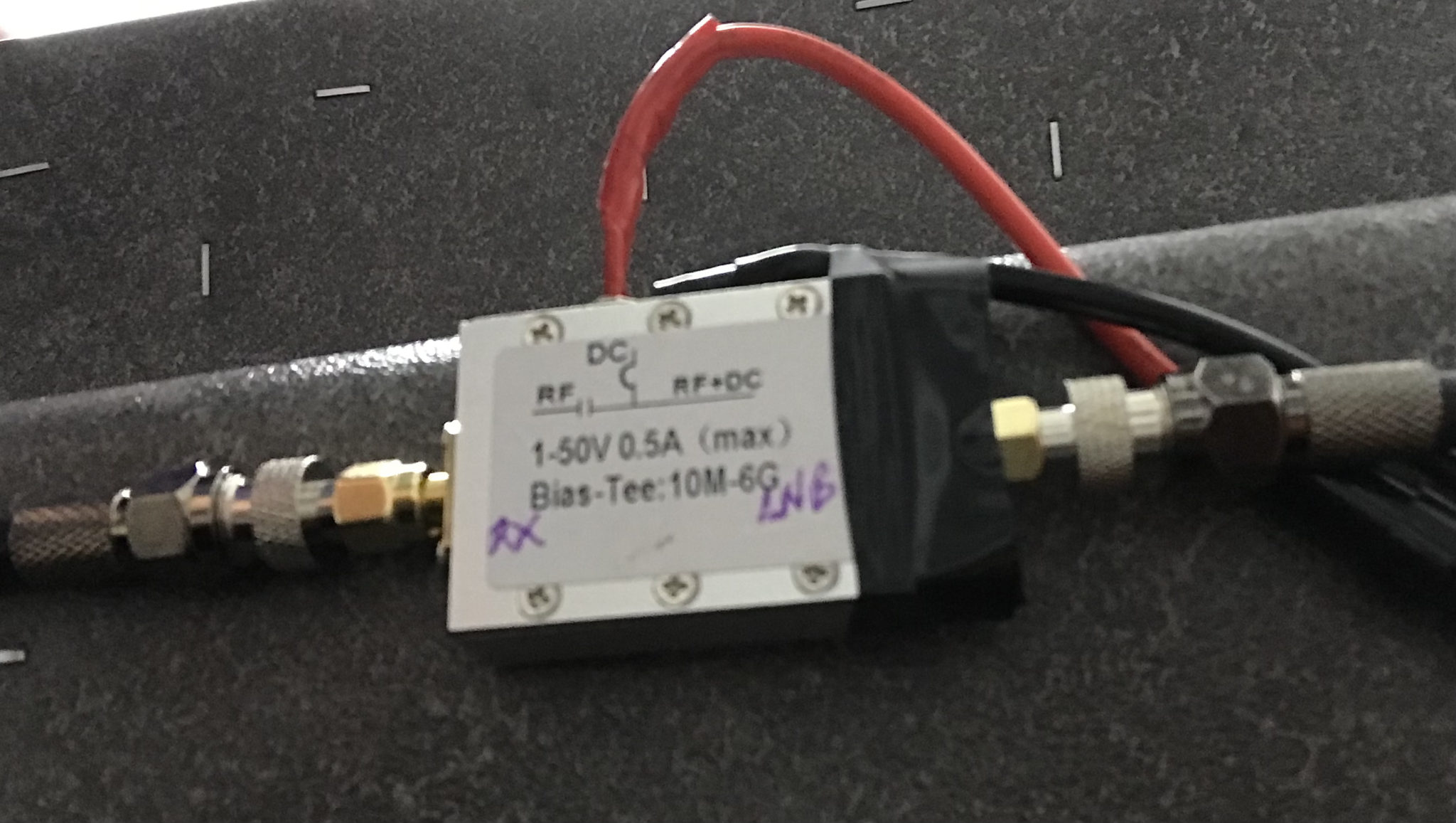
The 12v feed to the LNB is via the coax and is injected by the Bias-T device that is in the radio shack. This 12v feed powers the LNA and associated electronics in the LNB to provide a gain of 50-60dB.
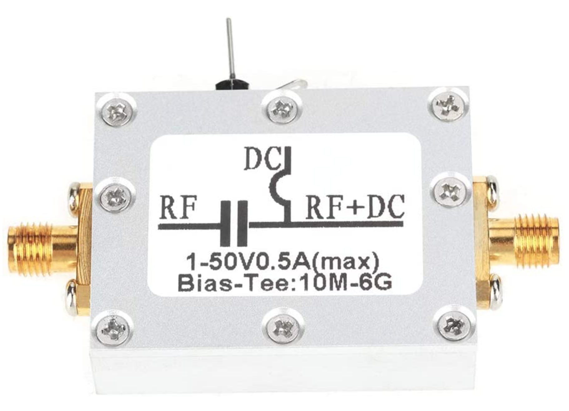
Bias-T to inject 12v feed into the coax for the Bullseye LNB

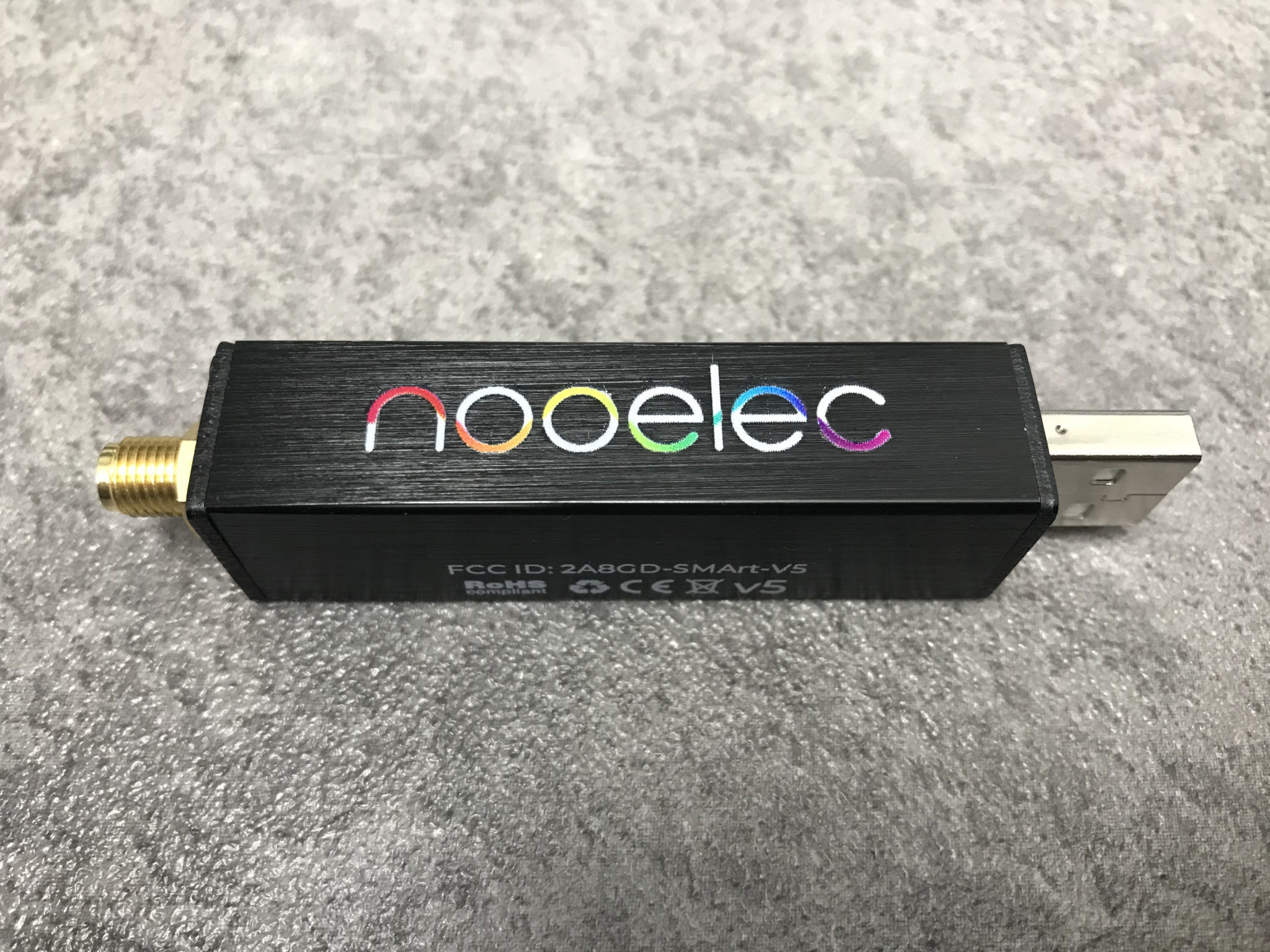
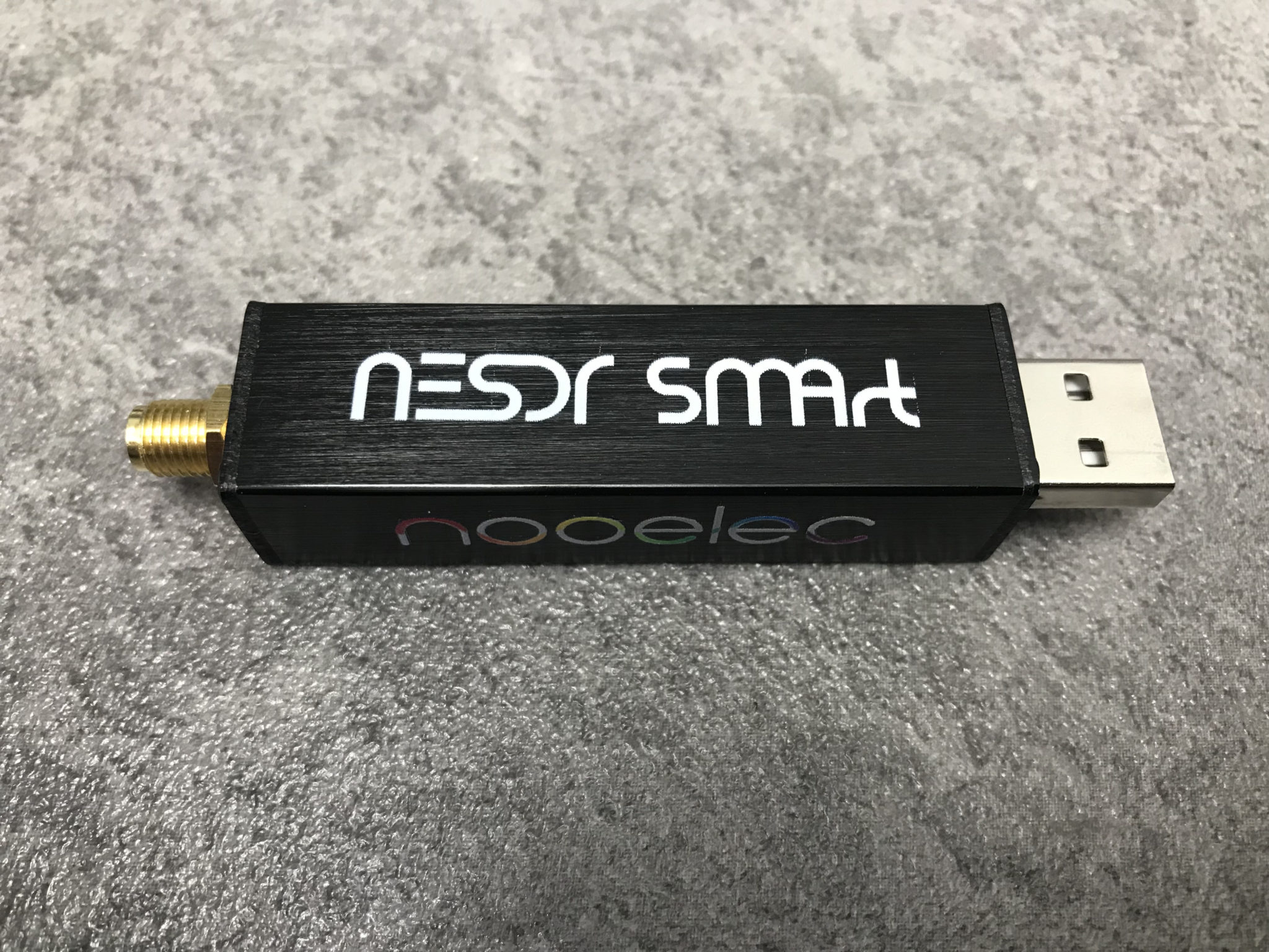
From the Bias-T the coax comes down to the NooElec SmartSDR receiver. This is a really cheap SDR device (<£35 on Amazon) based on the RTL-SDR device but, it works incredibly well. I originally used a Funcube Dongle Pro+ for the receive side however, it really didn’t handle large signals very well and there was a lot of signal ghosting so, I swapped it out for the NooElec SDR and haven’t looked back since.

The NooElec SmartSDR is controlled via the excellent Opensource software GQRX SDR. I’ve been using GQRX SDR for some years now and it’s proven itself to be extremely stable and reliable with support for a good number of SDR devices.

To enhance the operation of the SDR device I have added a Griffin Powermate VFO knob to the build. This is an old USB device that I originally purchased to control my Flex3000 transceiver but, since I sold that many moons ago I decided to use it as a VFO knob in my QO-100 ground station. Details on how I got it working with the station are detailed in this blog article.

Having the need for full duplex operation on the satellite this complicates things when it comes to VFO tracking and general control of the two radios involved in the solution and so I set about creating a QO-100 Dashboard using the great Node-RED graphical programming environment to create a web app that simplifies the management of the entire setup.
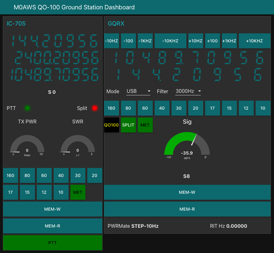
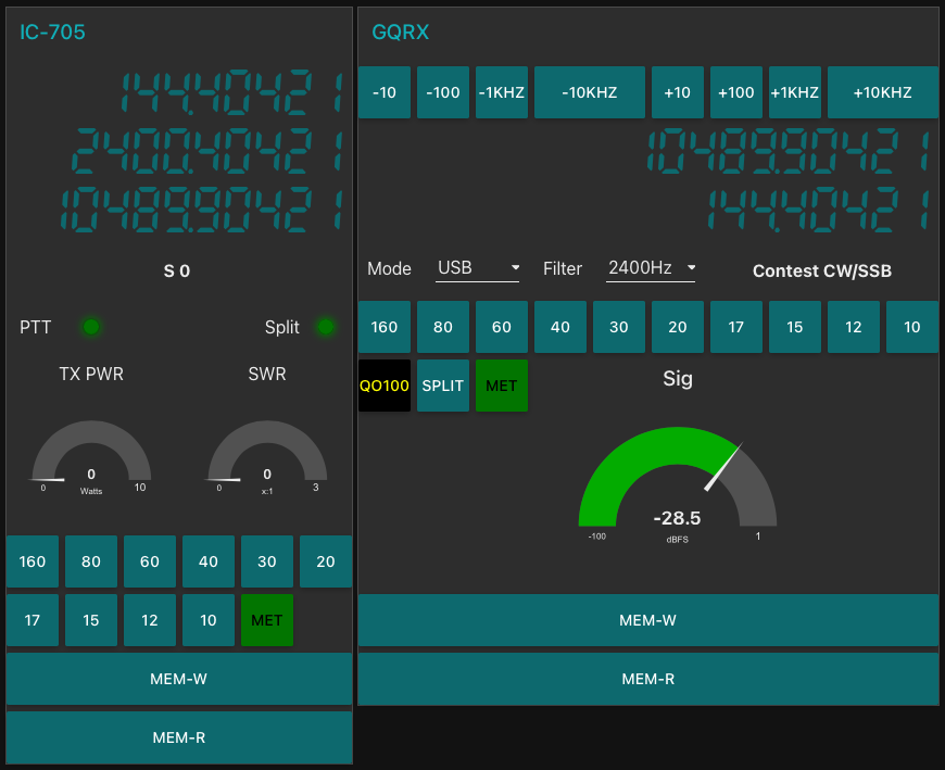
M0AWS QO-100 ground Station Control Dashboard built using Node-RED.

The QO-100 Dashboard synchronises the transmit and receive VFO’s, enables split operation so that you can transmit and receive on different frequencies at the same time and a whole host of other things using very little code. Most of the functionality is created using standard Node-RED nodes. More info on Node-RED can be found on the Opensource.radio Wiki or from the menu’s above.

I’ll be publishing an article all about the QO-100 Dashboard in the very near future along with a downloadable flow file.

I’m extremely pleased with how well the ground station works and have had well in excess of 500 QSO’s on the QO-100 satellite over the last last year.

More soon …

Using AI to generate modern QSL Cards

With the recent explosion of artificial intelligence (AI) art generators that are making the news of late for all the wrong reasons, I decided to see if I could put it to good use and design some futuristic QSL cards.

Having recently been contacted by the Special Callsigns QSL Manager and being advised that there were 18 QSL cards waiting for me, I decided it was time to create some QSL cards of my own for future use.

Having never used any form of online AI and not having any artistic abilities I was amazed how easy it was to create images using nothing more than a paragraph or so of text to describe what it was I wanted to create.

Since all the QSL cards I received were for contacts on the QO-100 satellite, I set out to create a visually futuristic QSL card that was based around a radio HAM operator and satellite communications.

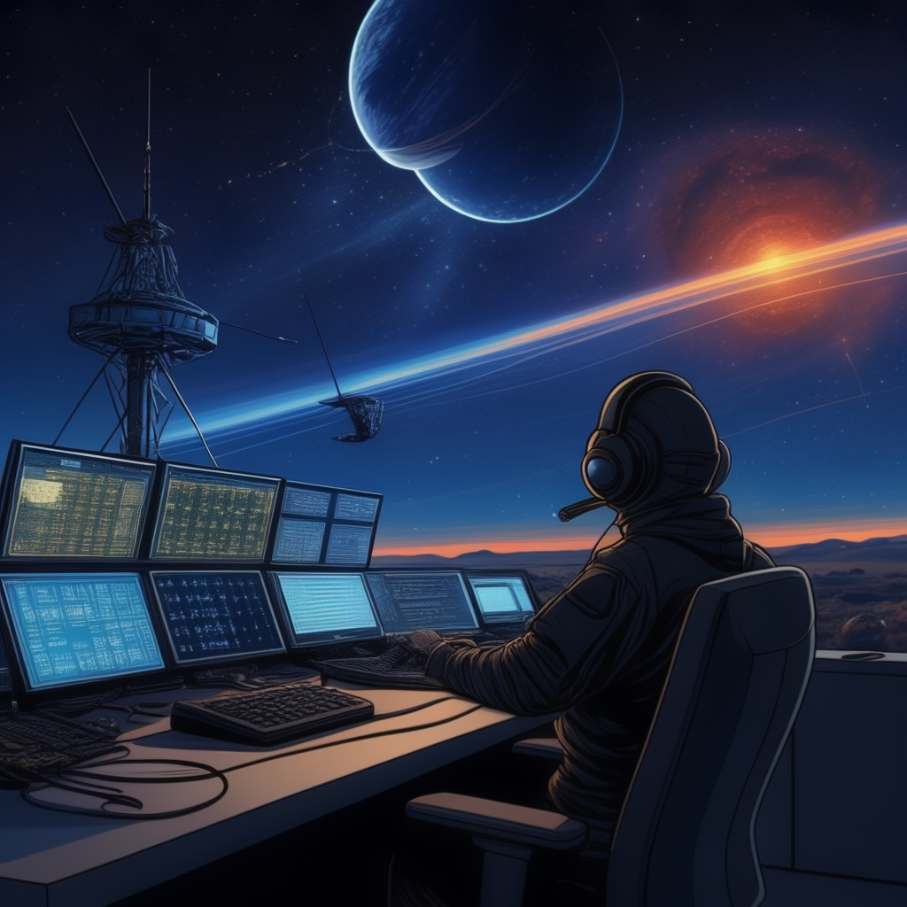
M0AWS - 1st attempt to create a futuristic QSL card using AI Art
M0AWS – 1st attempt at creating a futuristic QSL card image using AI Art

To my surprise the results of my first image generation were surprisingly good. The AI generated an image that resembled the simple text that I entered, although I never requested a one legged HAM operator!

Pleased with my very first attempt I gradually improved the description of what I was looking for, adding more and more detail to the text and including things that I wanted to see in the image. Over a fairly short period of time this approach started to generate some very interesting images.

With each iteration I gradually got closer to what I was trying to achieve but, never quite got exactly what I wanted so, I decided to rewrite the descriptive text adding even more information than before. The text was now a full blown paragraph with quite specific things described including the angle at which the scene was being viewed from.

The other option I wanted to try out was the theme functionality that the AI offered. This allows you to set a theme for the image from things like steampunk, cartoon, manga, real world and many more. The results were quite impressive and added yet another angle to the image generation.

I disappeared down the theme AI Art generation rabbit hole for quite some time and generated some very interesting and fun results. The best by far though was the Thunderbirds themed image, this did put a smile on my face!

M0AWS - AI Art QSL Thunderbirds Themed
M0AWS – AI Art QSL Thunderbirds Themed

At the other end of the spectrum I tried the Salvador Dalli theme, it produced an image that was very like the work of the famous artist but, wasn’t quite what I was looking for.

M0AWS - AI Art QSL Salvador Dalli Themed
M0AWS – AI Art QSL Salvador Dalli Themed

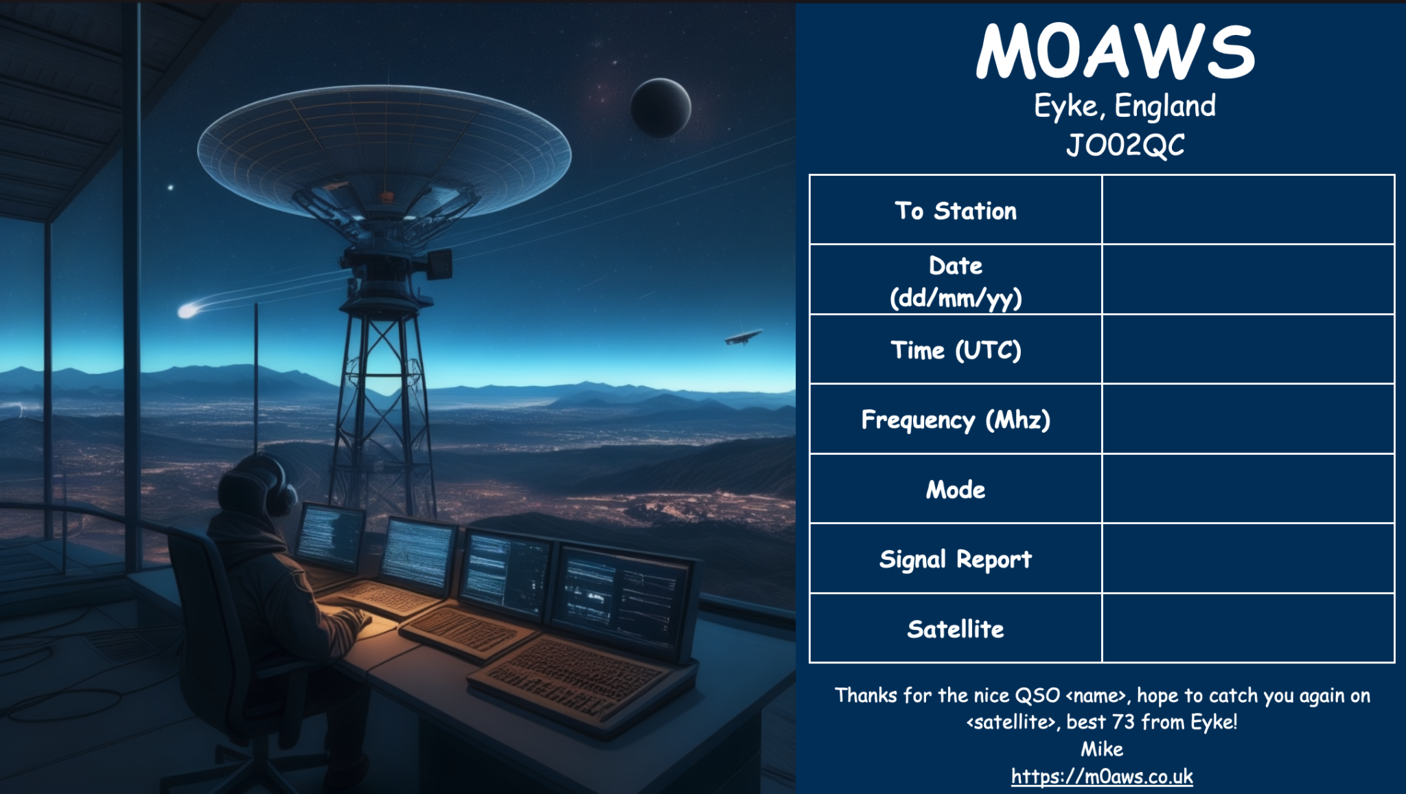
After much fun I eventually settled on the image I was after, a futuristic scene of a radio HAM with a satellite ground station over looking a mountain range and city below.

M0AWS Satellite QSL Card generated using online AI

I’m really pleased with the results from my ventures into AI generated art. The next challenge is to create a QSL card for HF bands Contacts.

More soon …
Just one little rain drop is all it takes!

We’ve not had rain for over 6 weeks here in Eyke, Suffolk. The ground is incredibly dry and dusty. The farmers have been pulling vast quantities of water from their bore holes for weeks to keep the crops alive and we’ve been putting extra water out for the birds and animals that visit our garden daily.

Then one night we had about 30mins of light rain, not much at all and it was consumed by the dry earth is seconds. By morning you’d never of known it had rained however, strangely the next day when I fired up my QO-100 ground station I noticed that my signal into the satellite was way down from it’s normal S9+10dB level. Checking drive into the up-converter and SWR at the IC-705 everything looked fine. I then decided to check the SWR from the 2.4Ghz amplifier output only to find that it was off the scale.

I checked inside the enclosure for water ingress but, all was bone dry as normal. I disconnected the coax cable from the output of the amplifier and the IceCone Helix uplink antenna, tested with a multimeter and found everything was fine, no short and perfect continuity.

After scratching my head for a few minutes I decided to take both the N Type and SMA connectors apart to look for water ingress. Since the inside of the enclosure was dry I wasn’t expecting to find anything.

The N connector at the Helix antenna end on the dish LNB mount was perfectly dry, no water ingress at all. The layers of self amalgamating tape I’d put over the connector had done its job perfectly. Shame I had cut the tape off to remove the plug!

Upon removing the SMA connector at the amplifier end of the coax I noticed a tiny drop of water in the bottom of the housing where the pin goes through the white plastic insulator, not a good sign.

Sure enough upon further inspection I found that the white plastic disc that is situated above the pin on the centre conductor was wet and the coax braid felt damp. I knew immediately this wasn’t good.

At first I didn’t understand how there could possibly be water in the SMA connector when the rest of the enclosure was dry. Where the coax goes into the top of the enclosure there is a water tight junction that tightly grips the coax cable and seals it, supposedly stopping water ingress.

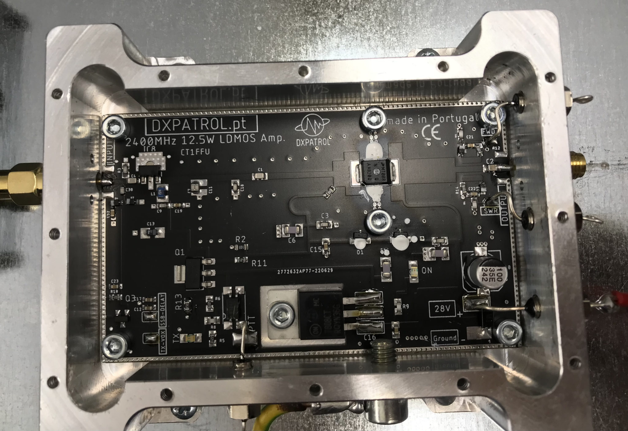
Since there was water in the SMA connector I feared that perhaps the water had gone further and entered into the amplifier so, I decided to remove the amp from the enclosure and remove the top cover to check.

2.4Ghz amplifier with top cover removed

After some close inspection I found the amp to be perfectly dry and free from water ingress, a relief for sure.

Before putting it all back together I decided solder on a pair of wires to the SWR and FWD-PWR pins on the amplifier and run them down into the radio room. This would then allow me to check the SWR and power output without having to get up to the enclosure with a multimeter.

Once this was done I then set about cutting 5cm of LMR-400-UF off at the SMA connector end so that I had a fully dry piece of coax cable to refit the SMA connector to. Having to do this outside and up a ladder wasn’t the easiest but, with a little perseverance and cooperation from the breeze I managed to get the pin soldered back onto the end of the coax and the connector back together.

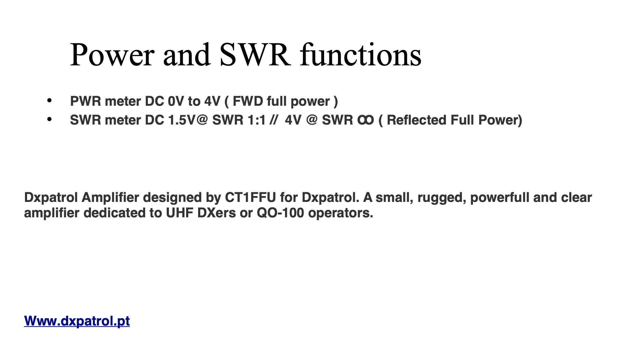
I reconnected the amp to the 28v feed so that I could check the SWR and power output at full rating instead of the lower 12v setting that I had been using. Checking the voltage on the SWR pin I found that it fluctuated between 0.2v and 0.44v. This wasn’t what I was expecting as the PDF manual for the amplifier states that with a 1:1 SWR you should see 1.5v on the SWR pin.

DXPatrol 2.4Ghz Amplifier Manual Page for SWR/FWD-PWR voltages

After checking all the connections and retesting and getting the same voltage reading I emailed Antonio at DXPatrol detailing my findings and asking if he could advise on the voltages I was seeing. Sure enough in no time at all he came back to me saying that the manual was incorrect and that I should see between 0.2 and 0.5v on the SWR pin for a good SWR match. Being happy that the readings I was getting were fine I emailed back thanking him for his swift reply and then moved on to check the power output safely in the knowledge that the SWR reading was within tolerances.

Checking the FWD-PWR pin I found that on SSB the voltage was fluctuating between 2v and 3v, this equates to 6w and 9w output, about right for SSB. Switching to CW mode I found the full 4v was present on the FWD-PWR pin confirming I had the full 12w output from the amp. Of course this set off “Leila” on the satellite immediately as I was a huge signal on the bird with such high power output and was a reminder to reconnect the amp to the 12v supply instead to ensure I didn’t exceed 5w output and thus keeping to a considerate level on the transponder input.

After further investigation I came to the conclusion that the water ingress could only of come from the cable inlet on the top of the enclosure, it had then run down the coax cable into the SMA connector. Somewhat annoying as the inlet is supposed to be a water tight fixing. Once I had everything back in the enclosure and securely fitted, I covered the cable inlet and coax in self amalgamating tape in the hope that this would stop any further water ingress. I also re-taped the N connector at the antenna end as well to ensure it was also protected from water ingress in the future.

2.4Ghz ground station enclosure ready for testing

I’m hoping this will be the end of my water ingress issues and that I have a dry 2.4ghz future ahead of me.

More soon …
My First QO-100 Satellite QSO

I’ve been waiting for over a week so far for a male to male SMA connector to arrive from Amazon so that I can connect the 2.4Ghz up-converter to the 2.4Ghz amplifier. Since it still hasn’t arrived I decided to connect the up-converter directly to the IceCone Helix antenna to see if I could get a signal into the QO-100 satellite.

To my surprise I could easily hear my CW signal on QO-100 even though the total output from the up-converter is only 200mW.

I didn’t expect to be able to hear my signal since it’s a tiny amount of power that has to travel some 22500 miles to the satellite but, I could hear it and was amazed that it was peaking S8 on my SDR receiver.

2.4Ghz Up-COnverter connected directly to the antenna bypassing the 2.4Ghz Amplifier
2.4Ghz Up-Converter connected directly to the antenna bypassing the 2.4Ghz Amplifier

Being excited I put out a CQ call that was soon answered by OH5LK, Jussi in Finland. Jussi gave me a 579 report which I was extremely pleased with. He was of course much stronger at a 599+ at my end. We had a quick QSO and exchanged details without any problems at all. Its really nice to get a QRPp contact without any QSB or QRM.

M0AWS QO-100 1.1m off-set Dish and IceCone Helix antenna ground station

Neil, G7UFO who I chat with regularly in the Matrix Amateur Radio Satellites room has posted a connector out to me so I’m hoping it will arrive on Monday and then I’ll be able to connect the amplifier and hopefully get a few SSB contacts.

UPDATE: I’ve since had 2 SSB contacts via QO-100 using just the 200mW O/P from the up-converter. Both times I got a 3/3 report not brilliant but, perfectly acceptable for the amount of power I’m putting out.

More soon …
Replacement for the Funcube Dongle Pro+

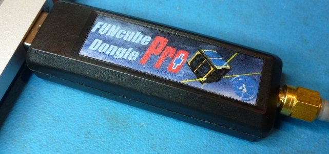
For some time now I’ve been using my Funcube Dongle Pro+ (FCD) as my QO-100 downlink receiver. It’s worked fairly well and has given me the ability to listen to stations on the satellite over the last few months.

During this time I have noticed a couple of things about the FCD that has lead me to the final decision to change to a new SDR device.

The first of these ‘things’ is the fact that the FCD gets seriously overloaded when there are multiple large SSB signals within the receive pass band. The only way to manage this is to constantly keep changing the software based AGC, mix and LNA settings to reduce the levels of the incoming signals so that the overloading stops. This is great except when you tune to a quiet part of the satellite transponder you have to turn all the settings back up again to be able to hear the weaker signals. After a while this becomes tiresome.

The fact that there isn’t a hardware AGC in the FCD is a major drawback when being used for satellite reception especially when it’s on the end of a very high gain LNB and dish antenna.

The second of these ‘things’ is the fact that I can’t see the whole transponder bandwidth at one time with the FCD as it has a very small receive bandwidth capability. This means that I am constantly tuning up and down the transponder to see if there are any stations further up or down in frequency.

Funcube Dongle Pro+
Funcube Dongle Pro+

Talking to more experienced satellite operators in the Matrix Amateur Radio Satellites room they recommended replacing the FCD with a NooElec NESDR SMArt v5 that has hardware AGC and is capable of receiving and displaying a much wider bandwidth.

Looking on Amazon the NooElec NESDR SMArt v5 is only £33 so I decided to place an order for one and give it try.

In typical Amazon style the SDR receiver arrived the next day and I wasted no time getting it plugged in and connected to the QO-100 ground station.

The NESDR SMArt v5 is based on the well known RTL-SDR that came onto the market some time back but, has a number of improvements in it that take it to the next level.

The first thing that I was happy with was the fact that the GQRX SDR software I use recognised it immediately on startup, no configuration or drivers were required it just worked, straight out of the box. Since I use Kubuntu Linux on my radio room PC I did wonder if I would need to get into installing extra libraries etc but, thankfully none of that was required.

Looking at the signals from the QO-100 satellite initially they appeared to be nowhere near as strong as they were on with the FCD. Looking at the settings in GQRX I noticed that the hardware AGC was off and the LNA setting was back to it’s default very low level.

I switched on the AGC and then increased the LNA setting to 38.4dB and found that the signals were now plenty strong enough on the display but, not overloading the receiver.

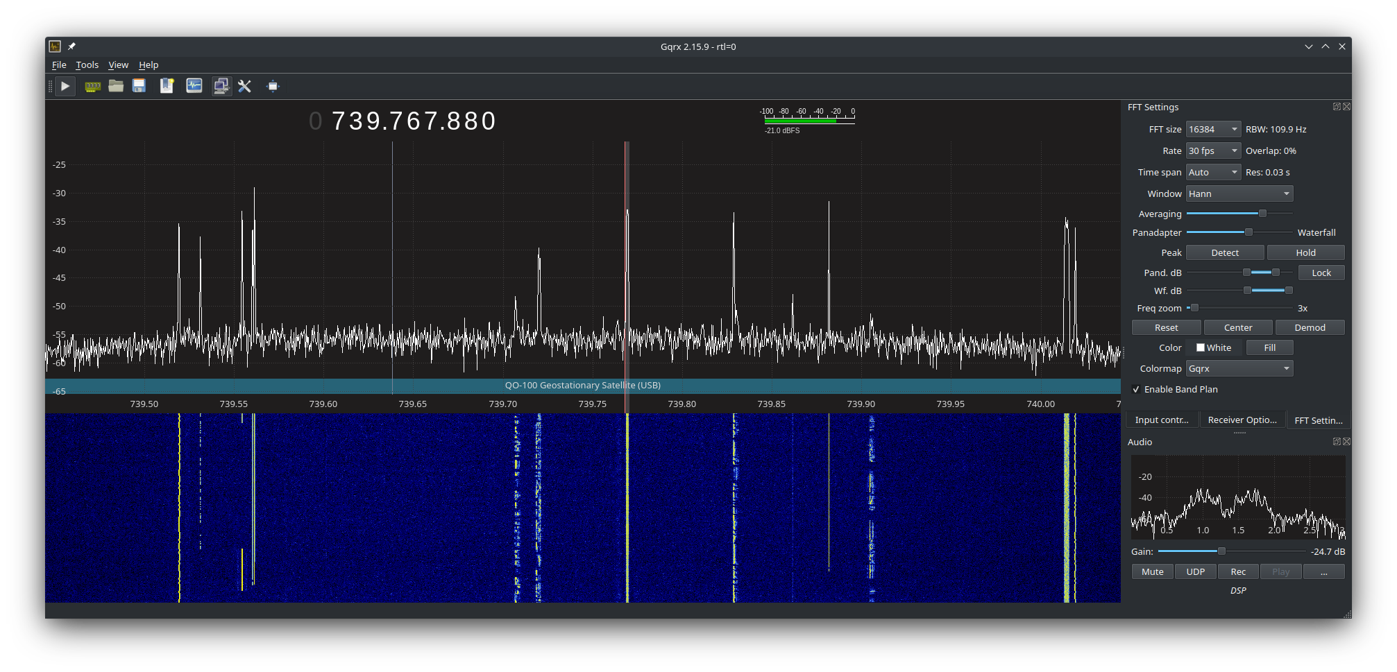
I then went on to adjust the display so that I could see the whole satellite transponder bandwidth on the screen. This is great as it enables me to see the low, middle and high beacons that mark out the narrow band section of the transponder and at a glance see all the stations using the satellite. This was a massive improvement in itself and one that I am very pleased with.

Using the NooElec NESDR SMArt v5 SDR it very soon became clear that it copes with multiple large signals in the pass band so much better than the FCD did. There’s no more overloading of the receiver, no more ghost signals appearing on the waterfall due to the front end not being able to cope and no more having to constantly keep playing with the settings to get things under control. The hardware AGC built into the SDR device does a great job at keeping it all under control whilst receiving a much wider bandwidth than the FCD ever could.

The satellite beacons are now received at S9+15dB without the receiver being overloaded, the first time I have seen this since starting out on my QO-100 venture.

The other thing that became obvious very quickly is that frequency stability is much better than it was with the FCD, it doesn’t drift up and down the transponder now and stays tuned exactly where I put it. It’s also on frequency whereas, the FCD was always 1.7Khz off frequency.

GQRX showing QO-100 Transponder signals

The NooElec NESDR SMArt v5 is very well put together, it has an aluminium case that acts as a heatsink (it does get warm!) and overall the build quality is much better than the plastic cased FCD. When I think that I paid close to £100 for the FCD and the NooElec NESDR SMArt v5 only cost £33, I am amazed at the build quality.

Overall I’m extremely pleased with the purchase of the new SDR, it slotted in perfectly as a replacement for the FCD, works great with GQRX, my QO-100 Node Red Dashboard and performs considerably better than the FCD. Overall money well spent!

You can find the NooElec NESDR SMArt v5 spec sheet here.

More soon …

QO-100 Satellite Ground Station Build

Over the long bank holiday weekend I started putting together my QO-100 ground station. To start with I’ve concentrated solely on the receive path. I’ll start the transmit path once I have the receive path operational at a satisfactory level.

A few weeks ago I purchased a 1.1m off-set dish antenna and a Bullseye LNB. These have been sat in my garage waiting for the weather to improve so that I could start the build in the dry.

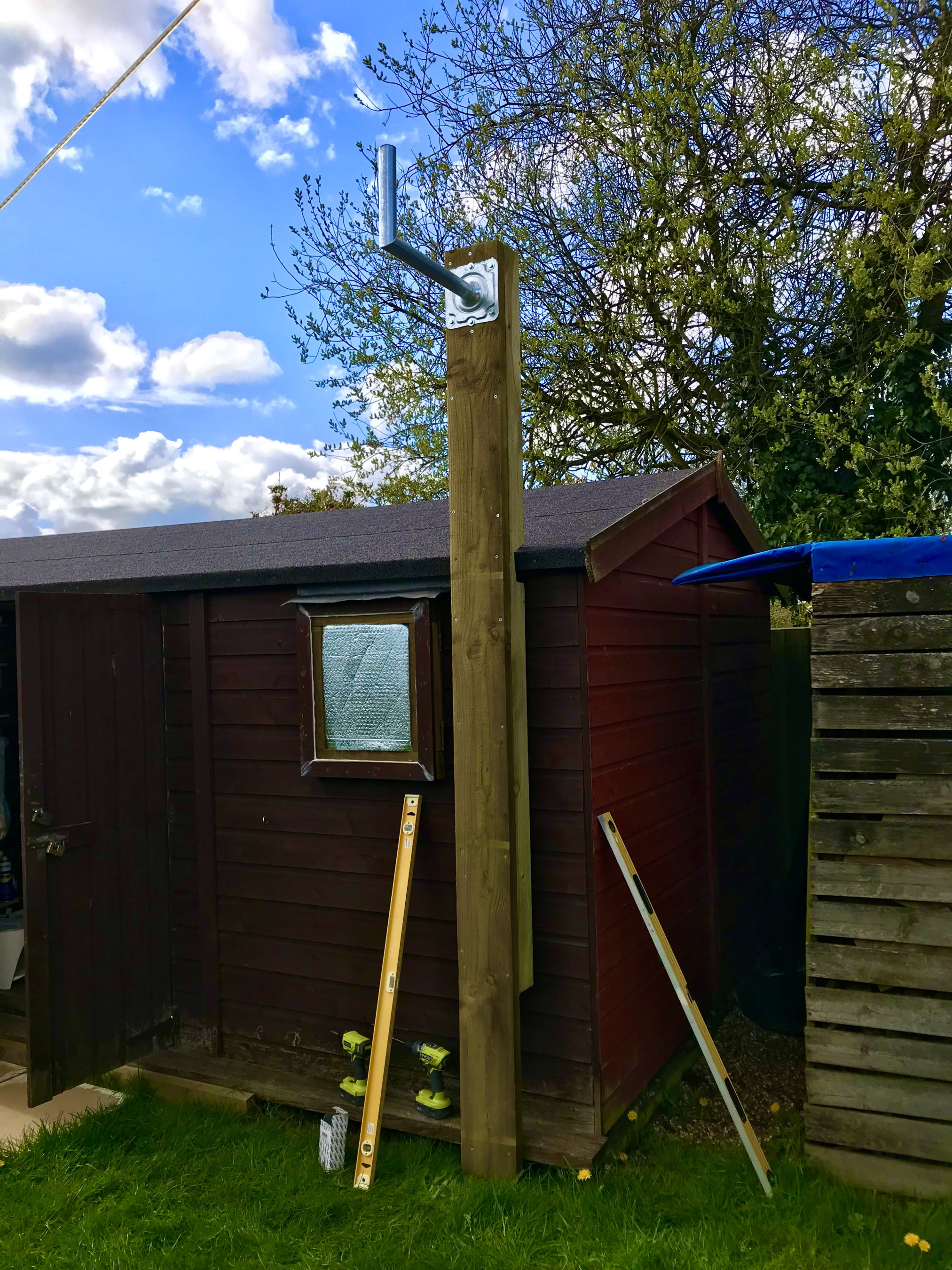
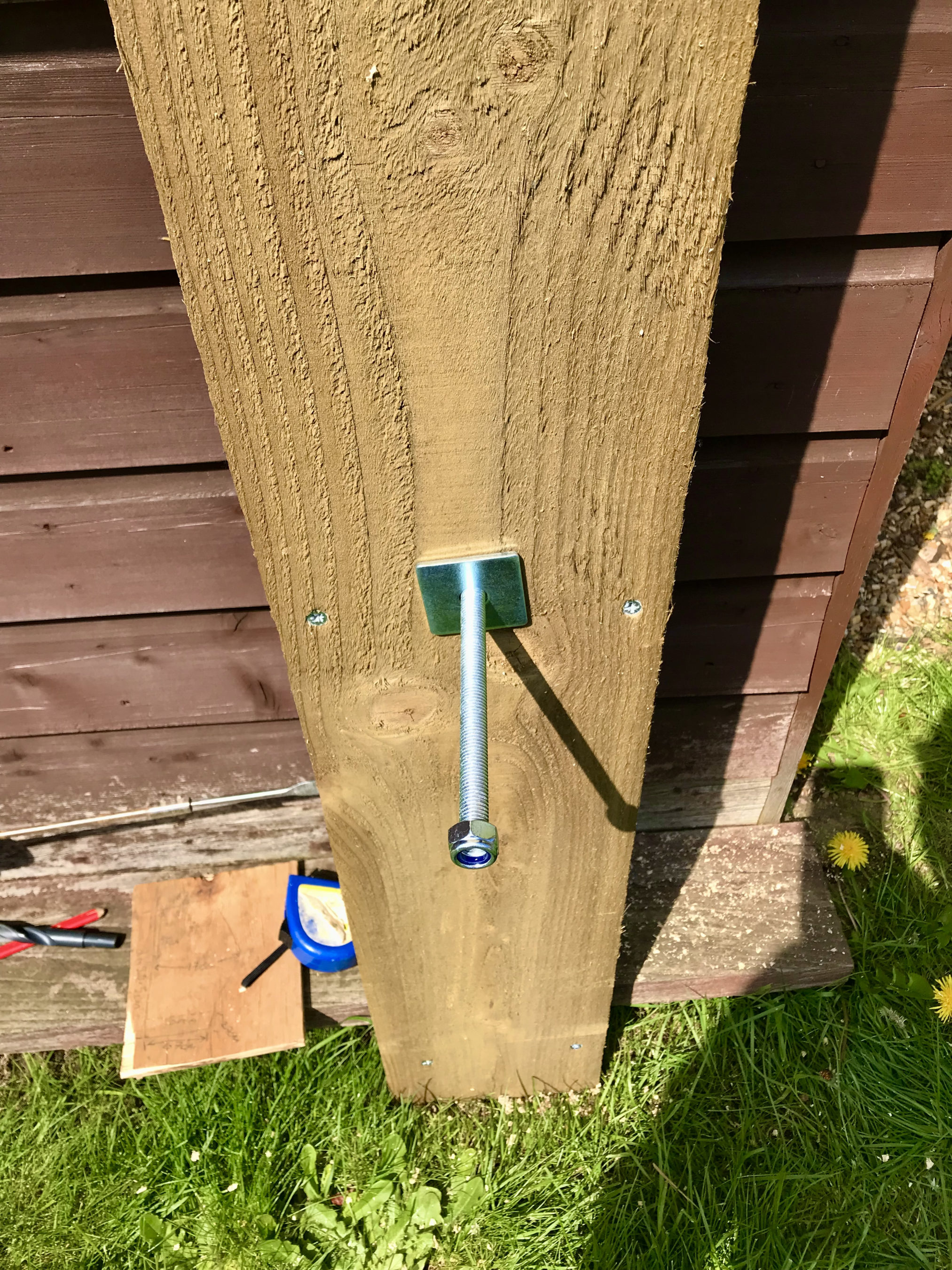
Fortunately we’ve had a mini-summer for the last 2 days and so I started work on getting the dish mount built. Using some timber from the local saw mill I made a braced 3m tall post which I screwed to the side of the cabin to provide a stable fixing platform. I used a couple of threaded bars to bolt through the walls of the cabin to ensure a solid fixing.

Next I mount the metal dish bracket to the top of the wooden post taking the total height up to around 3.2m above ground. This gives plenty of head clearance down below.

Next I assembled the dish and and attached it to the metal dish bracket at the top of the wooden post.

QO-100 1.1m dish mounted on the 3.2m AGL fixing

Attaching and cabling the Bullseye LNB was an easy job. I used some high quality coax cable that I purchase from the Satellite Superstore when I purchase the dish. I also had to set the LNB skew to -17.8 degrees. The marking on the LNB are tiny and go up in fives and so it’s pretty much impossible to get exactly -17.8 degrees so I turned it to 15 and then a tiny bit. It was as close I could get it!

Next I needed the information on where to point the dish. Fortunately there is a great web app on the BATC website where you can move a pin on a map to your location and all the information you need to align the dish is automagically calculated for you.

Armed with this info I set about aligning the dish. Getting it as close as possible I lightly locked off the dish and continued getting the coax in to the radio room so that I could connect it to my Funcube Dongle Pro+ (FCD) SDR receiver. Since the LNB needs a 12v DC feed I had to put inline a “Bias Tee” unit. This unit allows you to inject 12v onto the coax going up to the LNB but, stops it from coming back into the receiver. I used a Bias Tee that I purchased from Amazon with the Bullseye LNB.

Bias Tee mounted under the station desk

Connecting the coax to my Funcube Dongle Pro+ I was really pleased to see that I was receiving signals from the satellite perfectly well. I decided to take my laptop up onto the roof of the cabin and see if I could improve the reception further. To my amazement with very tiny changes in elevation and azimuth I was able to improve the QO-100 beacon signal by a further 10dB.

Being pleased with the dish alignment I started to tighten it so that it couldn’t move in the wind. Unfortunately this caused the dish to move a tiny amount which reduced the signal strength. I loosened the bolts off again and realigned the dish once more. This time when I tightened the clamps I did it a bit at a time on each bolt working my way round them so that the dish didn’t move. Doing it this way I still lost 1dB off the QO-100 beacon signal due to tiny amounts of movement but, decided I could live with the 1dB reduction.

QO-100 dish successfully mounted & aligned with HF antennas in the background

Below is a very short video clip showing a German station talking on the QO-100 satellite. As you can see the signal is nice and strong and extremely clear. I did find that the output from the LNB was actually too much for the FCD SDR and so I reduced the LNA setting in GQRX to 0dB. This reduced the background noise level considerably as the receiver was no longer being overloaded and made the signals much more prevalent above the noise floor.

Short video clip showing signal clarity from the QO-100 Satellite

I’m really pleased at the performance of the receive path and have now ordered the 2.4Ghz hardware from DXPatrol and Nolle Engineering so that I can build the transmit path.

I have also made some improvements to my QO-100 Node Red Dashboard so that I can work split on the satellite using my IC-705 and FCD SDR.

QO-100 Node Red Dashboard with ‘Split’ capability

Once the 2.4Ghz hardware arrives I’ll update the blog with progress.

More soon …

QO-100 TX/RX Dashboard

I’ve now completed the GQRX Receive and Icom IC-705 Transmit dashboard in Node Red. It was a fun project to put together and needed some javascript coding to get the functionality I wanted but, I got there in the end.

M0AWS QO-100 GQRX/IC-705 control dashboard

The dashboard looks fairly simple but, there is a lot behind the scenes to get it to this stage.

On the left is the Icom IC-705 transmit control panel. It shows the transmit frequency, power output and SWR reading. The SWR is so that I can check that the input into the 2.4Ghz transverter doesn’t have any connectivity issues. The “S0” will actually display the S Meter reading when the IC-705 is being used as a normal transceiver rather than being in QO-100 Duplex mode as shown above where the GQRX app and Funcube Dongle SDR are being used as the receiver.

The GQRX side of the dashboard shows the downlink frequency which tracks the uplink frequency of the VFO on the IC-705. This will ensure that the Funcube Dongle Pro+ SDR receiver will always be on the correct downlink frequency relative to the uplink frequency, thus I should always be able to hear my own signal coming from the QO-100 satellite.

Once taken out of QO-100 mode the two radios can be used independently on any of the HAM bands and can be switched using the buttons on the dashboard.

I also coded in a simple memory facility where a frequency can be stored in Node Red and recalled later on both the transmit and receive sides.

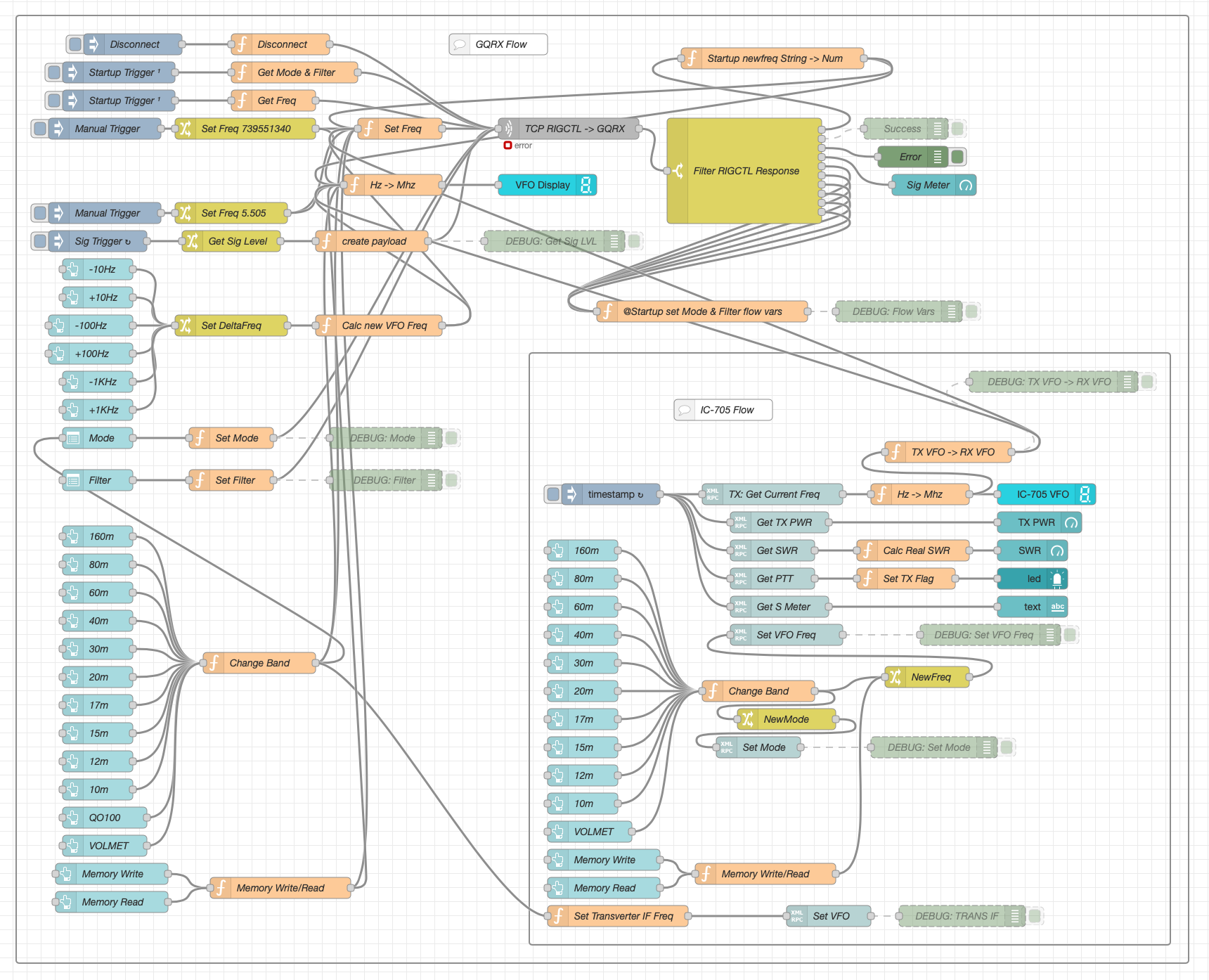
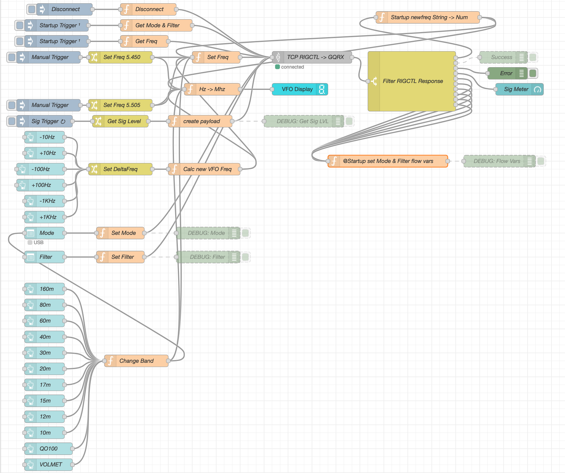
Looking at the dashboard it all looks simple and straight forward however, if you look at the Node Red flow it becomes obvious that this isn’t the case.

QO-100 Dashboard Flow in the Node Red Editor (Click for larger image)

There’s a lot to the flow to get the information from the receiver and transmitter so that it can be presented on the dashboard. There’s also some code to convert between Rigctl protocol used by the GQRX application and XMLRPC used by the IC-705 via FLRig and WFview. I had to also code around a bug in the Node Red XMLRPC node whereby you have to add 0.1 onto the VFO frequency for it to be passed onto the radio otherwise the information is never sent. This was a real pain of a bug to find but, with a little experimentation I found the problem and managed to code around it. The strange thing about this is that the 0.1 added onto the frequency isn’t actually passed onto the radio via the XMLRPC node, it just has to have that on input otherwise it doesn’t work at all. A very strange bug and hopefully one that will be fixed by the node developer in future releases.

All that is left to do now is add the temperature sensors dashboard to complete the dashboard. These haven’t arrived yet and so I’ve not been able to create the necessary flow to collect the data from them.

Hopefully this coming week the weather will improve and I’ll start getting the dish antenna up and the get the receive side working.

UPDATE: Further development of my QO-100 Dashboard has taken place, you can read all about it here.

More soon …

QO-100 Satellite Node Red Dashboard

Whilst I’ve been waiting for the weather to improve so that I can get my QO-100 dish antenna up I’ve been working on my QO-100 Node Red dashboard.

The idea of the dash board is to bring together the operating of the receiver and transmitter into one control centre so that the two separate devices are able to communicate and behave as if they were actually one device, like a transceiver rather than being individual components.

Ideally I would like to have the transmitter and receiver talking to each other such that when the VFO on the transmitter is incremented/decremented the receiver VFO also moves by the same amount.

By doing this the receiver VFO should always be in the right place on the 10Ghz band to hear my 2.4Ghz uplink signal and of course, any station coming back to my CQ calls.

So far I’ve only been working on the receive part of the Node Red flow, it’s certainly been a lot of fun getting it put together.

I control my Funcube Dongle Pro+ (FCD) using GQRX SDR on my Kubuntu PC. This software is working extremely well with the FCD and I’m happy with the level of functionality it offers.

GQRX SDR has the ability built in to control the SDR via remote TCP connection using RIGCTL protocol. Currently there isn’t a RIGCTL node available for Node Red so I have written a number of Javascript function nodes that provide the appropriate functionality in conjunction with a standard Node Red TCP node. This is working extremely well on the local LAN in the radio room and is proving to be very stable and responsive.

M0AWS QO-100 Node Red Flow – Receive Section

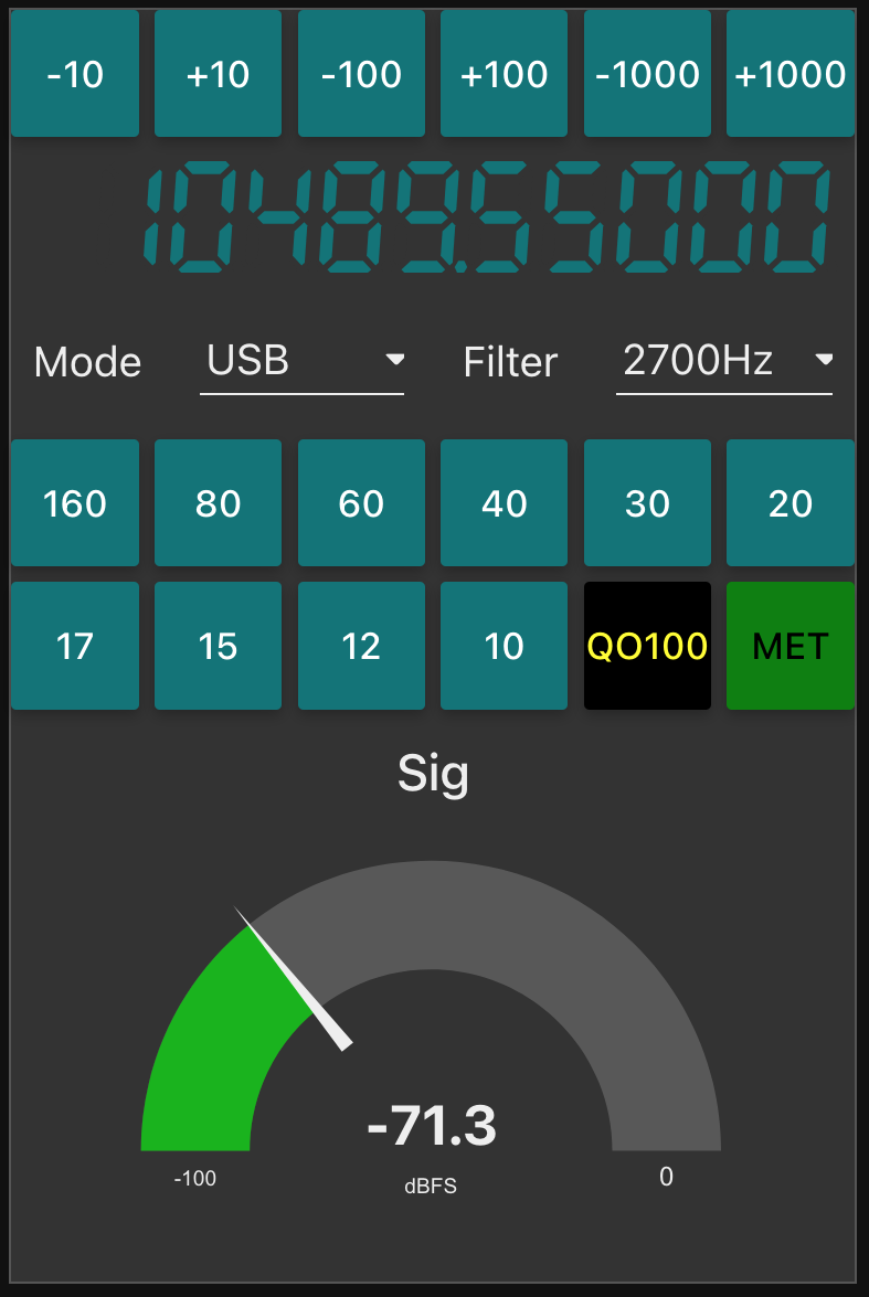
The flow for the receive section of the dashboard looks fairly complicated but, in reality it’s really not too difficult to get to grips with. The receive flow provides the facility to switch bands, switch modes, change receiver filter band width, display a realtime signal strength meter, receive +/- clarifier in 10/100/1000Hz increments and put the receiver into QO-100 mode where the SDR VFO is tuned to 739.550Mhz whilst the dashboard VFO shows the QO-100 downlink frequency in the 10Ghz band. This is all working very well and I’m happy with the initial result.

M0AWS QO-100 Receive Dashboard in QO-100 mode

I now need to start work on the transmit side of the QO-100 dashboard and get communications between my IC-705 transceiver and the FCD SDR working via Node Red. This could be a little more challenging as it will involve communicating with the IC-705 via WFView over wifi.

More soon …

QO-100 Station – Initial parts purchase

After much reading and viewing of youtube videos I have finally settled on the parts that I want to use to build my QO-100 Satellite ground station.

Initially I’m only going to build the receive path of the QO-100 station. From the articles and blogs I’ve read online all the experienced Amateur Radio satellite Op’s recommend getting the receive side sorted first and then moving onto the transmit path.

I need to stress here that I have no experience of radio above 433Mhz (70cm), a band that I have only used a handful of times. 99% of my Amateur Radio life has been spent below 30Mhz and so this is going to be a very new experience for me.

So, what am I going to purchase for the receive path?

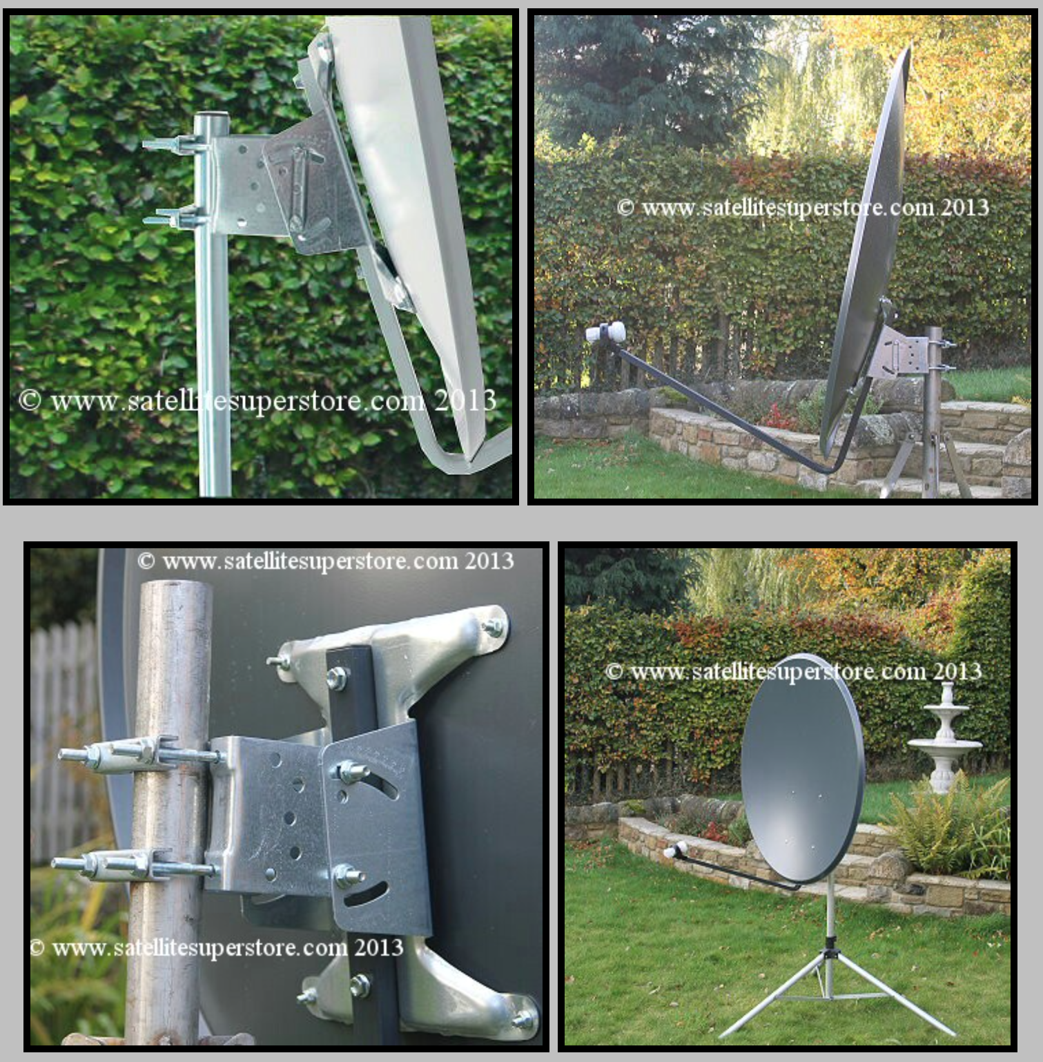
I’ve settled on a 1.1m off-set dish from the Satellite Super Store that should give me plenty of gain if I manage to get it pointed successfully at the bird.

I’ll pair a Bullseye 10Ghz TCXO LNB with the dish to give me a high stability receive path that shouldn’t wander too much up and down the band with temperature changes throughout the seasons.

1.1m Off-Set Dish for QO-100

The Bullseye LNB gets extremely good reviews from the HAM Satellite community, although it is a little on the expensive side compared to many others available. Since I only want to do this once I’ve gone with the more expensive option in the hope that it gives me the stability I’m looking for.

Since we’ve never had satellite TV here at home I’ve only just learnt that LNBs require a voltage feed since reading about other peoples QO-100 station builds. Most LNBs can be used for either horizontal or vertical polarisation and are switched by feeding with either 12v or 18v respectively. The LNBs also use this same voltage feed to do the frequency down conversation and some amplification of the received signal.

At the moment I’m only looking to get onto the narrowband part of the QO-100 satellite service and so I will need to feed the LNB with around 12v to ensure vertical polarisation is achieved. The easiest way to do this is to inject the 12v feed up the coax cable to the LNB.

Bullseye 10Ghz TCXO LNB

To achieve this I will need to purchase a little circuit called a Bias Tee. This relatively simple circuit consists of a capacitor and inductor combination that stops the 12v from going back into the receiver whilst at the same time stopping the RF from going back into the power supply.

Bias Tee units are relatively cheap to buy online and I have decided to get one from Amazon that has been recommended in a number of blogs posts I have read during my research.

Broco Bias Tee

With these parts ordered I now need to source the materials to mount the dish up above head height in the garden with a clear view of the sky in the direction of the satellite.

Getting the dish up high enough to be above head height will be important for when I get the 2.4Ghz uplink path in place. At these frequencies it’s important to ensure that no one is able to walk across the front of the dish whilst I’m transmitting. I’m hoping to get the dish up about 3m in the air in such a fashion that it is rigid enough to stop the dish moving around in the wind. I must admit I’ve not done any wind load calculations for the 1.1m dish so I’ll have to see how it goes over time. Fortunately where I want to put the dish is fairly well sheltered from the north wind that often howls through here so, hopefully it won’t be an issue.

More soon …