Looking to expand the device capability I stumbled across a really interesting little project that is still in the early stages of development but, is functional and worth trying out.
The TC²-BBS Meshtastic Version is a simple BBS system that runs on a RaspberryPi, Linux PC or virtual machine (VM) and can connect to a Meshtastic device via either serial, USB or TCP/IP. Having my M0AWS-1 Meshtastic node at home connected to Wifi I decided to use a TCP/IP connection to the device from a Linux VM running the Python based TC²-BBS Meshtastic BBS.
Following the instructions on how to deploy the BBS is pretty straight forward and it was up and running in no time at all. With a little editing of the code I soon had the Python based BBS software M0AWS branded and connected to my Meshtastic node-1.
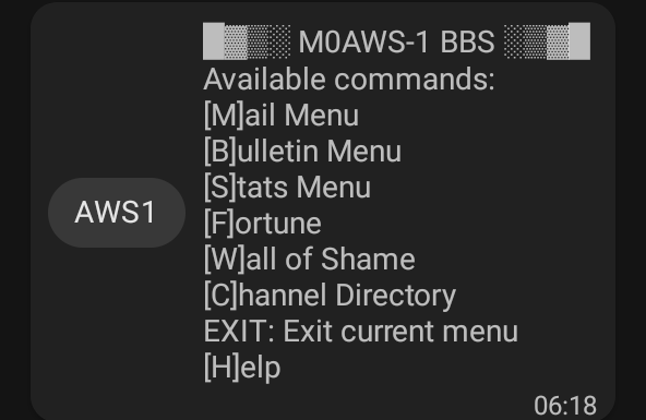
M0AWS Meshtastic BBS Main Menu accessible on M0AWS-1 node.
The BBS system is very reminiscent of the old packet BBS systems of a bygone era but, it is ideal for the Meshtastic world as the simple menus and user interface are easily transmitted in seconds via the Mesh using minimal bandwidth.
The BBS is accessible by opening a Direct Message session with the M0AWS-1 node. Sending the letter H to the node will get you the initial help screen showing the menu above and then from there onwards it’s just a matter of selecting the menu item and following the BBS prompts to use the BBS.
The BBS also works across MQTT. I tested it with Dave, G4PPN and it worked perfectly via the Meshtastic MQTT server.
This simple but, effective BBS for the Meshtastic network will add a new message store/forward capability to the Mesh and could prove to be very important to the development of the Meshtastic mesh in the UK and the rest of the world.
This solution has worked incredibly well from the outset and over time I’ve added extra functionality that I’ve found to be useful to enhance the overall setup.
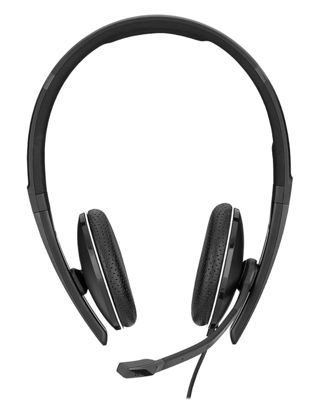
The latest addition to the ground station solution is a Sennheiser Headset that I picked up for just £56 on Amazon (Much cheaper than the Heil equivalents at the HAM stores!) and have found it to be excellent. The audio quality from both the mic and the headphones is extremely good whilst being light and comfortable to wear for extended periods.
M0AWS – Sennheiser SC 165 Headset
To incorporate this into the ground station the headset is connected to my Kubuntu PC and the audio chain to the IC-705 is sent wirelessly using the latest version of WFView. This works extremely well. The receive audio comes directly from the GQRX SDR software to the headphones so that I have a full duplex headset combination.
Audio routing is done via pulse audio on the Kubuntu PC and is very easy to setup.
Since I no longer have a mic connected to the IC-705 directly I found that I needed a way to operate the PTT wirelessly and this is where the latest addition to my NodeRed QO-100 Dashboard comes in.
Adding a little functionality to the NodeRed flow I was able to create a button that toggles the IC-705 PTT state on and off giving me the ability to easily switch between receive and transmit using a simple XMLRPC node without the need for a physical PTT button.
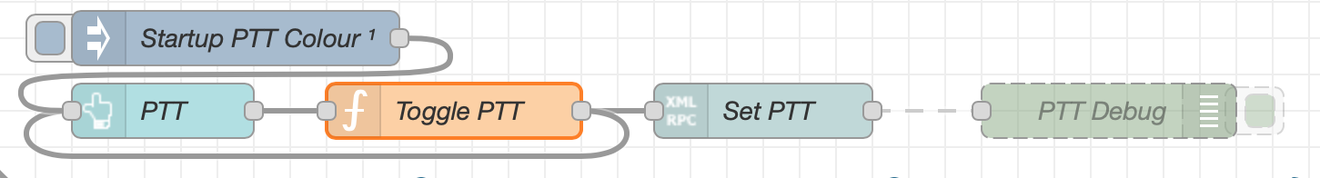
M0AWS – Additional NodeRed PTT Flow
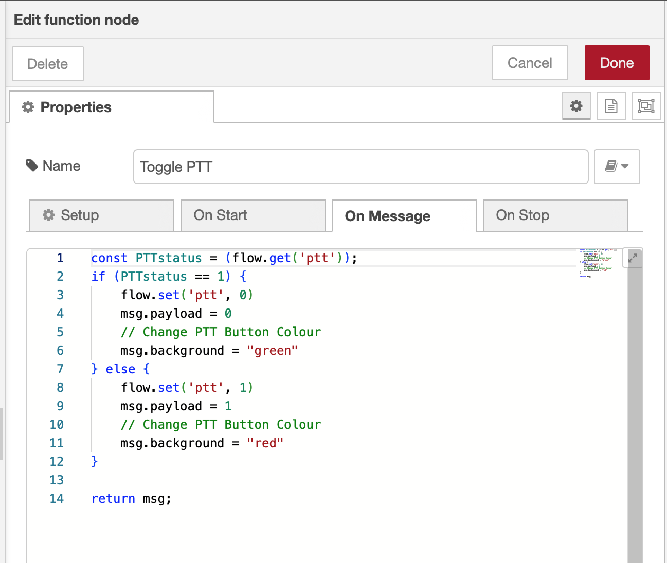
The PTT state and PTT button colour change is handled by the Toggle PTT function node shown in the above flow. The code to do this is relatively simple as shown below.
M0AWS – NodeRed Toggle PTT Function to change button colour
The entire QO-100 Dashboard flow has grown somewhat from it’s initial conception but, it provides all the functionality that I require to operate a full duplex station on the QO-100 satellite.
M0AWS – NodeRed QO-100 Dashboard complete flow
This simple but, effective PTT solution works great and leaves me hands free whilst talking on the satellite or the HF bands when using the IC-705. This also means that when using my IC-705 it only requires the coax to be connected, everything else is done via Wifi keeping things nice and tidy in the radio shack.
M0AWS – Updated NodeRed QO-100 Dashboard with PTT button
The image above shows the QO-100 ground station in receive cycle with the RX/TX VFO’s in split mode as the DX station was slightly off frequency to me. The PTT button goes red when in TX mode just like the split button shown above for visual reference.
As you can probably tell, I’m a huge fan of NodeRed and have put together quite a few projects using it, including my HF Bands Live Monitoring web page.
After initially finding that I couldn’t tune the 868Mhz ground plane antenna with the radials bent down at 45 degrees I decided to experiment to find out why.
Initially I had the radials connected to the 4 corners of the base of the chassis mount N Type socket. This works great if you have the radials completely horizontal and gives an SWR of 1.1:1 but, with the radials bent down at 45 degrees the best SWR is around 2:1.
M0AWS 868Mhz Ground Plane Antenna Close Up
Removing the radials from the base of the N Type chassis socket and soldering them to the outer of the N Type plug at the same level as the feed point for the radiating element I found that an almost perfect SWR can be achieved very easily.
M0AWS 868Mhz Antenna with radials soldered to the N Type Plug
It seemed weird to me that such a small change could have such a big effect on the obtainable SWR for the antenna but, as can be seen in the image below with the radials soldered to the N Type plug and bent downwards I immediately got an SWR of 1.07:1 and a much wider SWR curve.
M0AWS 868Mhz Antenna SWR curve with radials soldered to N Type plug.
By making my own antennas I’m learning a lot about antenna design for the 800-900Mhz frequency range. Minor changes seem to have a much bigger impact than they do at much lower frequencies.
Following on from my last article on improving the Heltec ESP32 v3 antennas I found during the installation of the 90 degree SMA connector that the device was very sensitive to stray capacitance from things around it. After reconnecting my VNA I found the SWR curve would change substantially depending on what the device was near and so I set about rectifying this.
I decided to remove all the insulation from the single radial inside the unit and then added two more radials to increase the ground for the antenna to tune against. I then removed the N type plug with the antenna connected to it and made a new antenna from a piece of 1.5mm solid core insulated mains wire connected directly to the N type socket, without using an N type plug. Tuning to resonance was much easier than before and I soon had the SWR down to 1.2:1. Moving the device around and placing near to other objects the SWR curve was now much more stable than before with only very slight changes in curve shape.
M0AWS Updated 868Mhz Antenna
Making this change to the 868Mhz antenna has shown an improvement in signal strength from my node-1 device of almost +0.5dB, every dB counts when you only have 100mW to play with!
The Bluetooth antenna update has made a massive improvement to the usability of the device via the iOS Meshtastic app. Being able to have a reliable, solid connection from anywhere in the house is great and I no longer lose messages because I’ve strayed outside the range of the Bluetooth connection.
I now have 2 new Heltec ESP32 v3 devices on the way to me and will be getting those configured and operational outside with external antennas in the hope of hearing some nodes locally to me.
The Heltec ESP32 v3 LORA devices have a coil type Bluetooth/Wifi antenna on the PCB from the factory. This antenna doesn’t work particularly well and has very limited range so, I decided to do something about it.
Getting out the calculator a quarter wave at 2400Mhz is 29.7mm. Looking at the coil antenna on the PCB I decided the best way to connect the new antenna would be to solder it to the coil of the existing antenna. This would short out the coil completely whilst creating a solid mount point for the new antenna.
After a little measuring I decided to use a 31mm long piece of 1.5mm hard core mains cable for the new antenna. I stripped back the insulation from one end of the wire so that the exposed copper wire was exactly the length to short across all the windings of the coil antenna on the PCB.
Attaching replacement Bluetooth Antenna to the Heltec ESP32 v3 Device
Attaching the the wire to the coil was easy enough to do but, it’s worth pointing out that you need to be quick so that the heat doesn’t transfer down onto the PCB desoldering the coil antenna from the device.
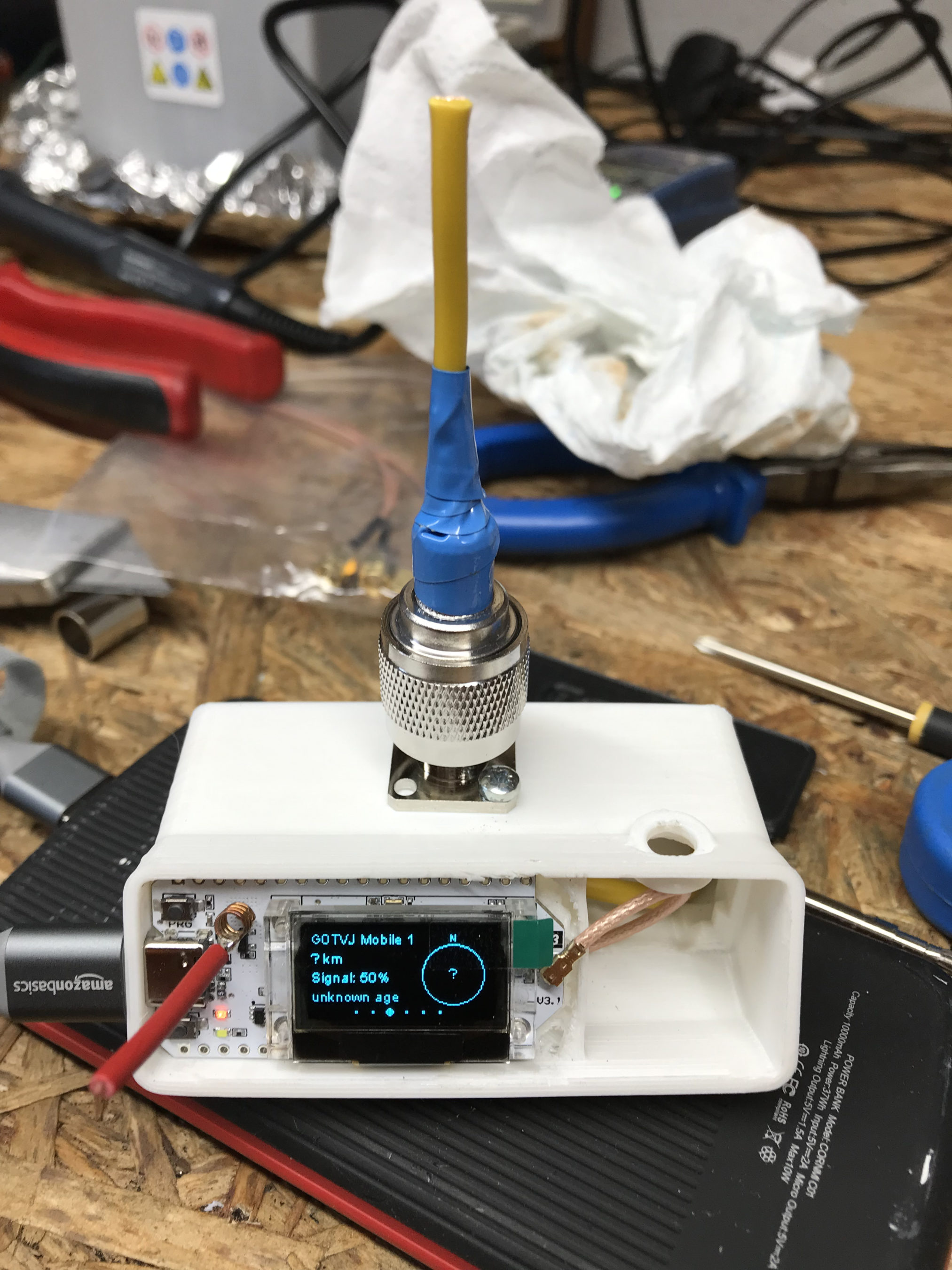
Whilst tinkering with the Bluetooth antenna I decided I would also make a neat little quarter wave 868Mhz vertical antenna for this device whilst I had it all apart. This is my Meshtastic node-2 and it’s sole purpose is to allow me to use my iPad to send/receive messages via bluetooth which are then forwarded on to my base node-1 in the house. Node-1 is connected to the house wifi and the Meshtastic MQTT server. This combination allows me to message people on the mesh even though there are no local nodes within RF range.
Running the numbers for the 868Mhz antenna the vertical will need to be around 82.1mm long with a radial of similar length. I had to hand a very nice SMA to N Type chassis mount socket that would be ideal to mount the antenna to the case. I drilled out the holes in the case, measured out the wires and attached it all to the case. Connecting the antenna to the N Type socket I connected my VNA and set about tuning the antenna to resonance.
M0AWS Hidden Radial for the 868Mhz Heltec Antenna
Squeezing the radial and SMA connector into the case I realised I really could do with a 90 degree SMA connector so, I quickly ordered one from Amazon which will be delivered tomorrow. Connecting up my VNA, I had to trim the antenna down to get it to resonance. The SWR ended up at 1.2:1 which is ideal. I ended up cutting off more wire than I thought I would to get the antenna to resonance but, this is due to the extra capacitance caused by the insulation on the wire. If I had used bare copper wire then I wouldn’t of had to cut so much off. I eventually ended up with around 72.9mm of wire for both the antenna and radial.
M0AWS Heltec ESP32 v3 Device with replacement Bluetooth and 868Mhz Antennas
Putting the device back into the case and connecting the USB battery the device fired up and immediately connected to my node in the house. Checking the signal strength of node-1 in the house I could see a 7dB increase in signal strength compared to the little wire antenna that comes with the device. This is a significant improvement for such a simple antenna and well worth the effort.
Next I had to drill a hole in the front of the Heltec case so that the Bluetooth antenna could poke out the front and be bent up vertically. This worked out really well and improved the Bluetooth range massively.
M0AWS Completed alterations to the Heltec ESP32 v3 antennas
Putting the node back in the house and taking my iPad down to the end of the garden some 30m away I could instantly connect to the device via Bluetooth from my iPad, something I’d not been able to do prior to adding the new antennas. I can now use the Heltec device via Bluetooth from anywhere in the house or garden making it much more accessible.
It’s amazing the difference an hour and two little pieces of wire can make to these devices and is well worth the effort.
I’ve been on the QO-100 satellite for about 7 months now and I have to admit I love it!
Having a “Repeater In The Sky” that covers a third of the world really is a wonderful facility to have access to however, there is one thing that I find tiring and that is the high level of background noise that is always present.
Even though the signals are mostly 59-59+15dB the background “hiss” is very pronounced and gets very tiring after a while, especially if like me you have tinnitus.
Currently I’m using a NooElec Smart SDR for the receiver and GQRX SDR software on my Kubuntu Linux PC. This works great but, there is one short fall, there is no DSP Noise Reduction (NR) in the software or hardware.
To fix this I recently invested in a BHI Dual In-Line Noise Eliminating Module. The unit itself is nicely put together and has a good combination of inputs and outputs making it easy to connect up to my MacBook Pro to record QSOs and connect my headphones at the same time.
M0AWS BHI Dual In-Line Noise Eliminating Module
At £189.95 plus postage from BHI direct it’s not cheap but, it is nicely put together and comes complete with a power lead and a couple of cheap audio cables. The quality of the knobs and mechanisms is good apart from the little grey DSP Filter Level knob that feels cheap and is very wobbly on the switch below. I’m not sure how long this is going to last with prolonged use and will most likely need replacing with something a little sturdier at some point in the future.
Overall noise reduction is good but, the audio amplifiers on the Audio Input Level and Line Out Level distort very early on in their range and you cannot get them much above level 5 before distortion starts to appear on the received signal. This is disappointing as my headphones are of reasonable quality and are let down by the distortion creeping in from the audio amplifier in the BHI unit.
I’ve tried altering the levels on the input from the IC-705 and no matter what I cannot get a good audio signal in my headphones without some distortion on the higher frequency ranges.
Overall the device does do what I want, it reduces the background “hash” considerably reducing the fatigue whilst chatting on the satellite. Below is a recording from a conversation on the satellite showing the noise reduction performance of the BHI module.
M0AWS Example BHI DSP NR Recording
The recording starts with the BHI DSP NR off, at 00:07 the DSP NR is switched on, you can clearly hear the difference. At 00:23 the DSP NR is turned off again and at 00:36 the DSP NR is turned on again. The BHI DSP NR Module is set with the DSP Filter Level set at 3 out of 8 which appears to be the best level to use. Switching to level 4 starts to introduce digital artefacts to the audio which only gets worse the higher the DSP Filter Level goes.
With a setting above level 3 there really isn’t much improvement in noise reduction and the audio becomes progressively more affected by the digital artefacts than it does from the background noise.
M0AWS BHI Dual In-Line Noise Eliminating Module with Icom IC-705 QO-100 Ground Station
The only other problem I have with the BHI Dual In-Line Noise Eliminating Module is that is comes in a plastic case. The case itself is solid and of good quality however, it offers no RF shielding whatsoever and the unit is extremely susceptible to RF getting into the audio chain and then being heard during transmit in the headphones and via the line out connections. For the money I would had expected the unit to come in a metal case that provides proper RF shielding. This is a real shame as it lets the unit down considerably.
As setup in the photo above I am using 300mW O/P on 144Mhz from the IC-705 into a perfect 1:1 SWR presented by the DX Patrol 2.4Ghz Upconverter via some very high quality LMR-400 Coaxial cable from Barenco but, I get terrible RF interference via the BHI unit during the transmit cycle. Considering I am only using 300mW I dread to think what it may be like if I was using a 100w HF radio. This is something I need to investigate further as it really is very annoying.
Moving the unit to a different location in the radio room does help a bit but, doesn’t solve the problem completely. At 300mW RF O/P I really didn’t expect there to be a problem with RF getting into the BHI unit.
Having a proper line-out facility on the BHI unit really is nice as it makes it very easy to connect to my MacBook Pro to obtain good quality recordings of signals on the QO-100 satellite as can be listened to above.
Overall I am happy with the BHI Dual In-Line Noise Eliminating Module but, do wish that more care had been taken over using a metal case instead of a plastic case to protect the unit from RF ingress and better audio amplifiers within the unit that don’t distort/clip so early on in their O/P levels.
Is this the perfect noise reduction unit?
No but, overall it is better than nothing and does help to reduce the background noise to a more acceptable level reducing the overall fatigue during prolonged conversations on the QO-100 satellite.
UPDATE: I tried the BHI unit with my FTDX10 on the HF bands and the RF interference is horrendous, even when using QRP power levels! This device clearly hasn’t been designed to work in an RF environment and the total lack of shielding or isolation lets it down terribly. If you are an SWL then this unit is fine but, if like me you like to monitor your transmitted audio whilst on air through headphones then this isn’t the unit for you. To prove the problem isn’t in the radio shack I put the BHI unit in the house some 30m away powered by 12v battery with nothing connected but a pair of headphones and still the unit suffered from RF interference even at QRP levels.
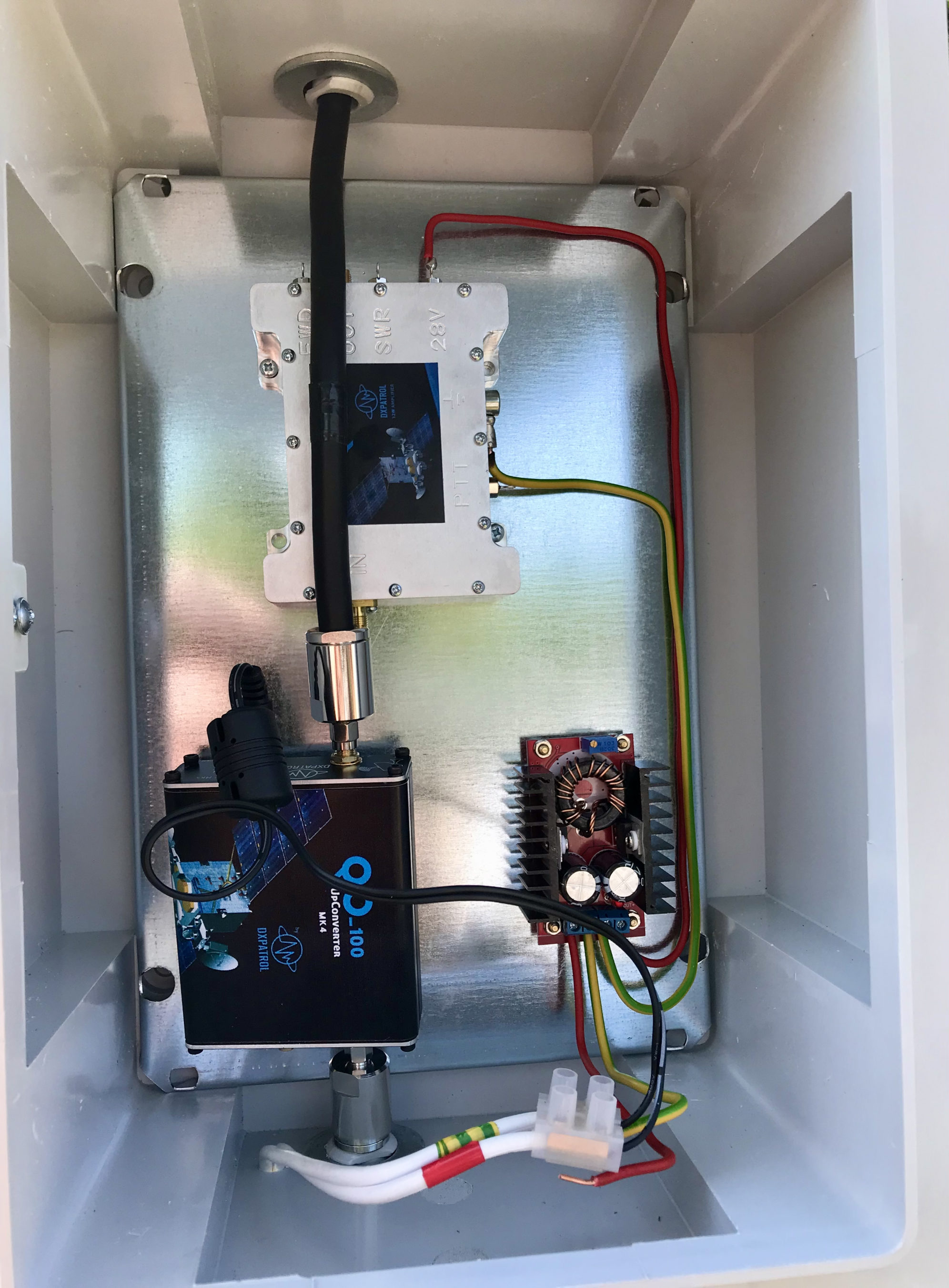
I’ve been waiting for over a week so far for a male to male SMA connector to arrive from Amazon so that I can connect the 2.4Ghz up-converter to the 2.4Ghz amplifier. Since it still hasn’t arrived I decided to connect the up-converter directly to the IceCone Helix antenna to see if I could get a signal into the QO-100 satellite.
To my surprise I could easily hear my CW signal on QO-100 even though the total output from the up-converter is only 200mW.
I didn’t expect to be able to hear my signal since it’s a tiny amount of power that has to travel some 22500 miles to the satellite but, I could hear it and was amazed that it was peaking S8 on my SDR receiver.
2.4Ghz Up-Converter connected directly to the antenna bypassing the 2.4Ghz Amplifier
Being excited I put out a CQ call that was soon answered by OH5LK, Jussi in Finland. Jussi gave me a 579 report which I was extremely pleased with. He was of course much stronger at a 599+ at my end. We had a quick QSO and exchanged details without any problems at all. Its really nice to get a QRPp contact without any QSB or QRM.
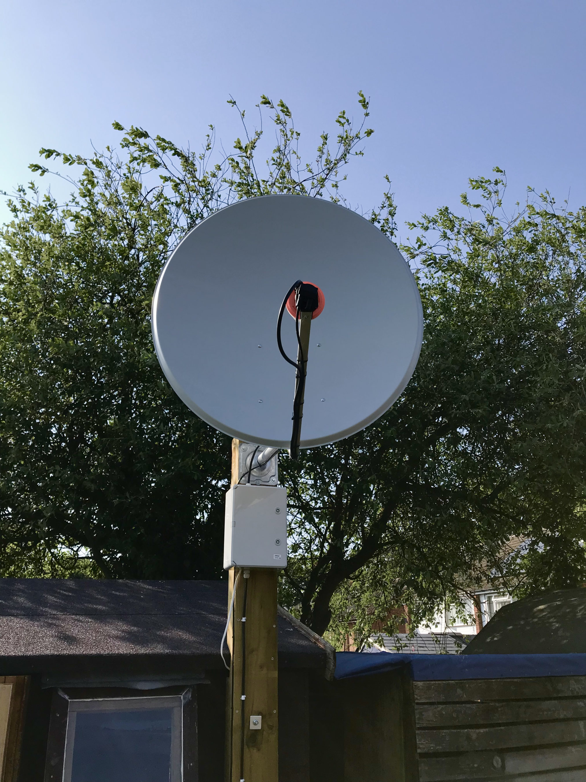
M0AWS QO-100 1.1m off-set Dish and IceCone Helix antenna ground station
Neil, G7UFO who I chat with regularly in the Matrix Amateur Radio Satellites room has posted a connector out to me so I’m hoping it will arrive on Monday and then I’ll be able to connect the amplifier and hopefully get a few SSB contacts.
UPDATE: I’ve since had 2 SSB contacts via QO-100 using just the 200mW O/P from the up-converter. Both times I got a 3/3 report not brilliant but, perfectly acceptable for the amount of power I’m putting out.
For the last 24hrs I’ve had the RaspberryPi2 transmitting WSPR on 20m and 10m connected to my EFHW Vertical antenna. So far not a single spot on the 10m band, I’m assuming the band hasn’t opened in the UK over the test period.
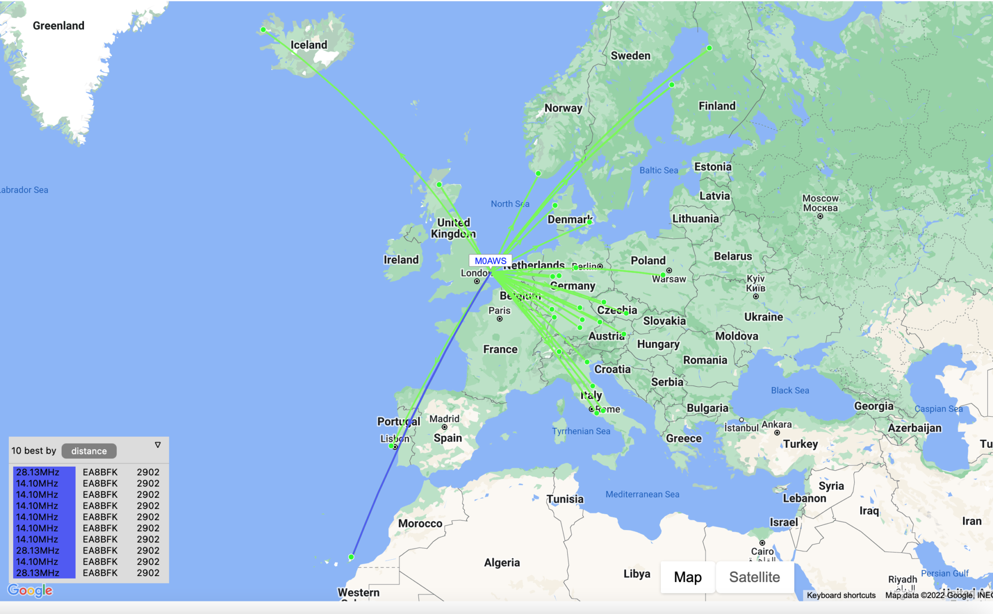
WSPR 20m band reports over the last 24hrs
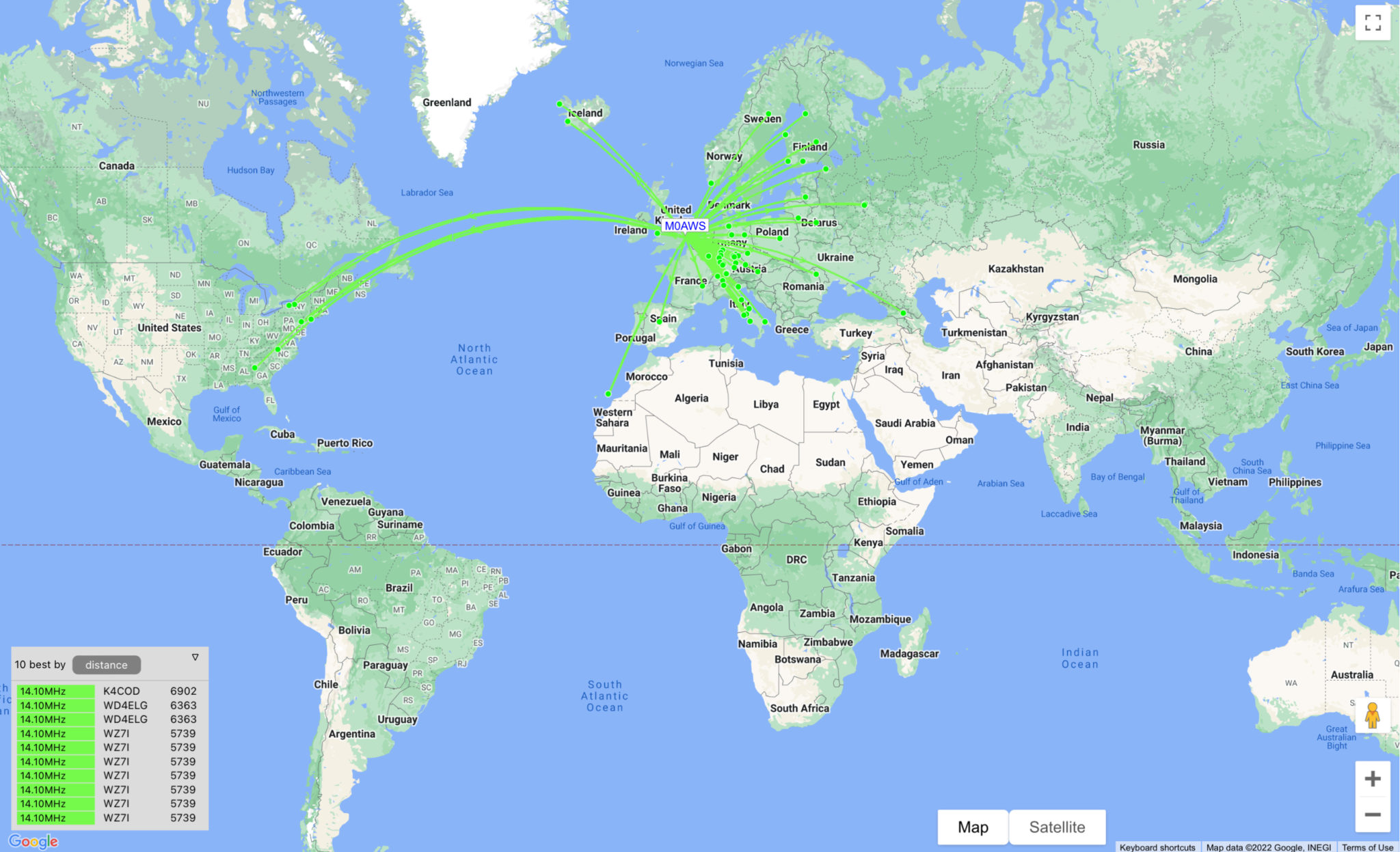
Results on 20m continue to impress with reports from the USA, West Africa coast and as far east as Georgia.
I’ll check the signal on 10m later today using my IC705 to ensure it is transmitting ok and then will leave it running for another 24hrs to see what happens.
UPDATE:
It appears there’s been a reliable opening on both 10m and 20m to the Canary Islands just off the west coast of Africa so far today.
The Weak Signal Propagation Reporting Network (WSPR) known as “Whisper” in the HAM community is a QRP/QRPp beacon mode that is used by many HAMs around the world to see pretty much realtime propagation on the HF bands.
I first started using WSPR when I lived in France some years ago and it proved invaluable for assessing antenna performance and directivity. It’s not a new mode by any means and nowhere near as popular as it used to be as it’s really been superseded by FT4/8 these days that provides the same functionality but, with QSO capability too.
Having an old RaspberryPi hanging around and reading about the WSPR software that’s available for it now I decided to put the Raspi to good use and build a WSPR beacon for the 20m band that I could leave on 24/7.
Having the EFHW Vertical at the end of the garden means that I can connect it directly to the Raspi without the need for an ATU as it’s fully resonant. (It’s actually resonant on 20m and 10m)
I normally run both my RaspberryPi mini computers completely headless and then SSH in to them from my MacBook Pro and decided this was the best way to go with the WSPR beacon too since the WSPR software is command line based and doesn’t require a GUI.
First thing to do was to upgrade the OS from Debian Buster to Bullseye. It’s been a while since I used the Raspi but, it fired up perfectly and connected to the LAN without issue.
After a little time I had the O/S updated to Bullseye and the Raspi was ready for the software build.
The WSPR program comes in source code only so, this means you have to compile it yourself. This isn’t a big job as it comes complete with a makefile.
Using a terminal run the following commands to download and compile the WSPR source code.
So first thing to do is install git.
sudo apt-get install git
Once git is installed I downloaded the software from the git repository.
It only takes a few seconds to download the software which is stored in a new directory called “WsprryPi”.
Before the code can be compiled there’s a small issue with the includes in one of the source code files that needs to be resolved so that the code compiles without error.
cd WsprryPi
vi mailbox.c
Using your favourite command line editor, ‘vi‘ in my case I added the following line into the include statement at the top of the code.
#include <sys/sysmacros.h>
Once added the full include statement looked like this:
Once done, I saved the file ready for compilation.
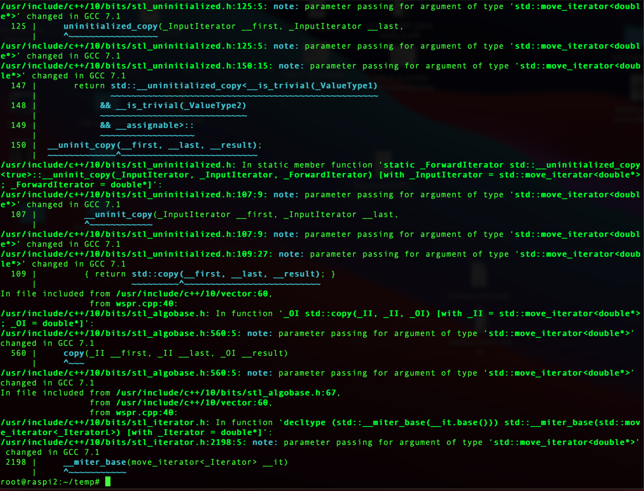
Compiling the code is easy, just run the make command and sit back and watch all the compiler messages scroll across the screen.
make
Compiling the WSPR source code
Once compiled without errors, I just needed to install the binary.
make install
At this point the software is ready to go.
I quickly soldered up a lead to go from the RaspberryPi GPIO pins to the Coax cable that is connected to the EFHW vertical antenna in the garden and connected it all up ready to test.
RaspberryPi 2 WSPR Beacon connected to EFHW vertical for 20m/10m bands
Pins 7 and 9 on the Raspberry Pi’s GPIO pins are where the signal is output. Pin 9 is the Ground pin, and pin 7 is the Signal pin. Pin 7 goes to the inner of the coax and pin 9 to the ground side of the coax.
The purple cable is the ethernet cable connecting the Raspi to my local LAN so that I can access it remotely via SSH. I’ve powered the Raspi off of the USB port on the wifi access point in the radio shack which is always on.
Once it’s all connected it’s just a case of starting the WSPR program from the command line as user root.
wspr -s -r M0AWS JO02 10 20m > ./wspr.log &
I run the WSPR program as root user so that it has the correct privileges to access the devices to communicate with the GPIO headers, if you want too start it as your normal user then you’d need to use sudo to gain the root privileges.
The command line options I’ve used are as follows:
-s
Check NTP before every transmission to obtain the PPM error of the crystal
-r
Repeatedly, and in order, transmit on all the specified command line freqs.
M0AWS
My Callsign
JO02
My Locator Square
10
The power being used in dBm
> ./wspr.log &
Redirects all output to wspr.log in the current directory and then puts the program into the background so that it is left running when I log out.
Once the program is started you can monitor progress by using tail on the log file.
tail -f ./wspr.log
The output you will see will be something like this.
Desired center frequency for WSPR transmission: 14.097100 MHz
  Waiting for next WSPR transmission window...
  TX started at: UTC 2022-07-17 16:06:01.015
  TX ended at:   UTC 2022-07-17 16:07:51.638 (110.623 s)
Desired center frequency for WSPR transmission: 14.097100 MHz
  Waiting for next WSPR transmission window...
  TX started at: UTC 2022-07-17 16:08:01.015
  TX ended at:   UTC 2022-07-17 16:09:51.639 (110.624 s)
Desired center frequency for WSPR transmission: 14.097100 MHz
  Waiting for next WSPR transmission window...
  TX started at: UTC 2022-07-17 16:10:01.015
  TX ended at:   UTC 2022-07-17 16:11:51.642 (110.627 s)
Desired center frequency for WSPR transmission: 14.097100 MHz
  Waiting for next WSPR transmission window...
  TX started at: UTC 2022-07-17 16:12:01.015
  TX ended at:   UTC 2022-07-17 16:13:51.639 (110.624 s)
Desired center frequency for WSPR transmission: 14.097100 MHz
  Waiting for next WSPR transmission window...
  TX started at: UTC 2022-07-17 16:14:01.015
  TX ended at:   UTC 2022-07-17 16:15:51.639 (110.624 s)
Desired center frequency for WSPR transmission: 14.097100 MHz
  Waiting for next WSPR transmission window...
  TX started at: UTC 2022-07-17 16:16:01.014
  TX ended at:   UTC 2022-07-17 16:17:51.639 (110.624 s)
Desired center frequency for WSPR transmission: 14.097100 MHz
  Waiting for next WSPR transmission window...
  Obtained new ppm value: 4.09996
  TX started at: UTC 2022-07-17 16:18:01.015
  TX ended at:   UTC 2022-07-17 16:19:51.640 (110.624 s)
Desired center frequency for WSPR transmission: 14.097100 MHz
  Waiting for next WSPR transmission window...
  TX started at: UTC 2022-07-17 16:20:01.014
  TX ended at:   UTC 2022-07-17 16:21:51.638 (110.624 s)
Desired center frequency for WSPR transmission: 14.097100 MHz
  Waiting for next WSPR transmission window...
  TX started at: UTC 2022-07-17 16:22:01.004
  TX ended at:   UTC 2022-07-17 16:23:51.628 (110.624 s)
You can pass multiple bands on the command line if you want to hop around bands.
It’s also recommended that you add a low pass filter between the Raspi and coax connection to help suppress any harmonics that may be generated. You can make one easily enough using just a capacitor or there are a number of prebuilt low pass filters specifically made for the GPIO hat on the Raspi online.
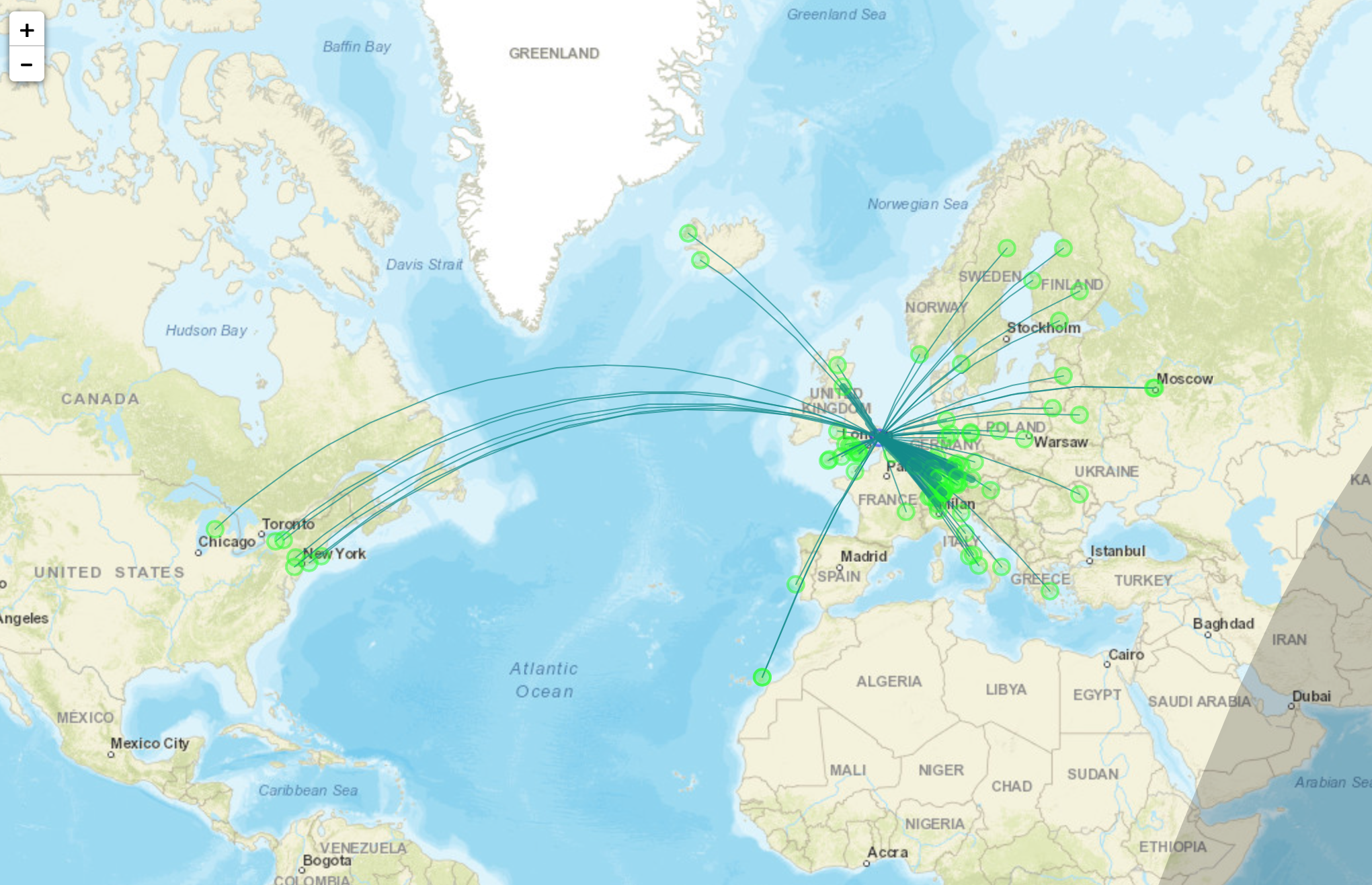
With only 10dBm (10mW) output from the RaspberryPi it’s surprising the distances that the signal travels. In no time at all I had reports from all over Europe and as the day progressed reports started coming in from Iceland, the USA and Russia.
Map showing stations that heard M0AWS on WSPR
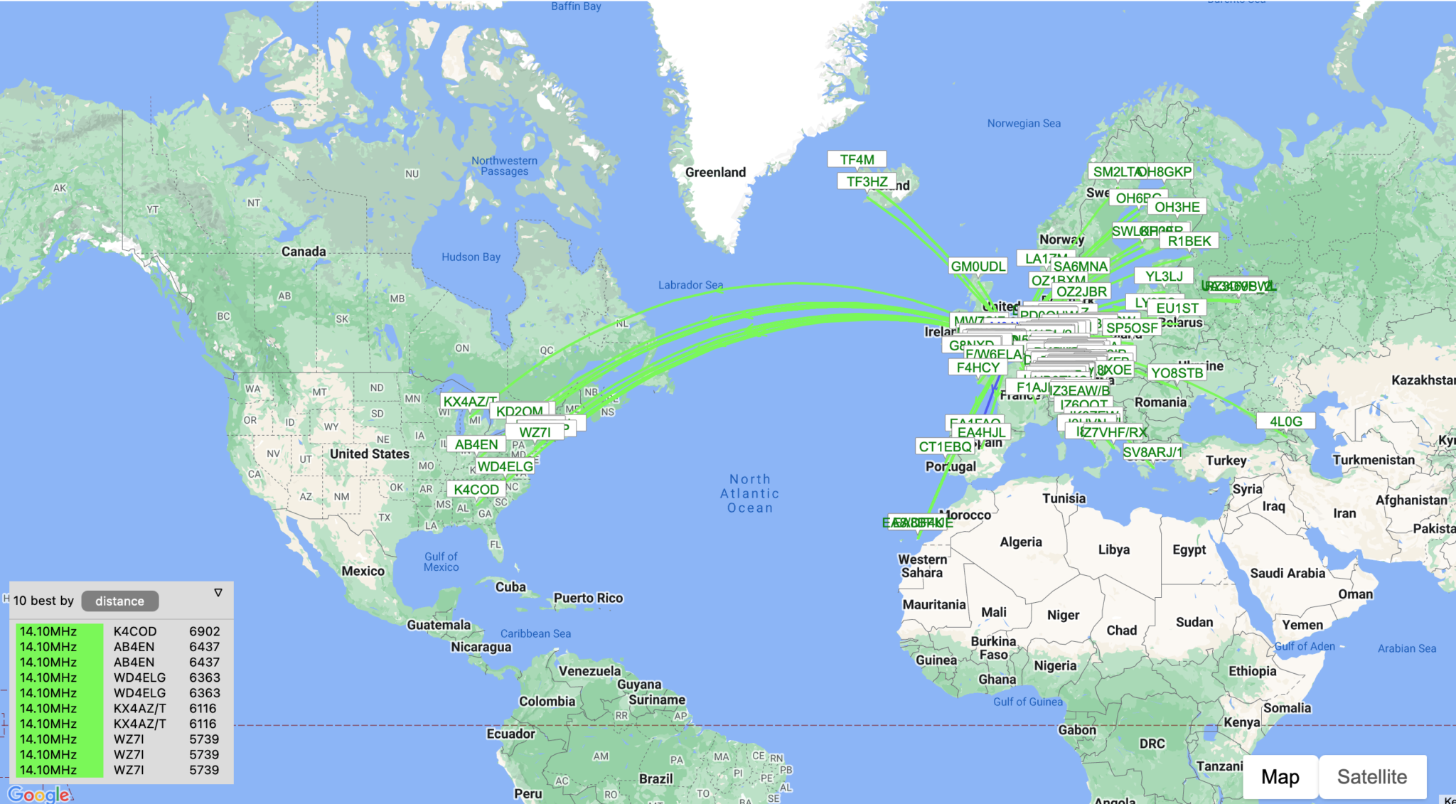
I used http://wspr.aprsinfo.com WSPR monitoring website to watch progress as the day went on and after 24hrs had been heard by a number of stations over 3000 miles away.
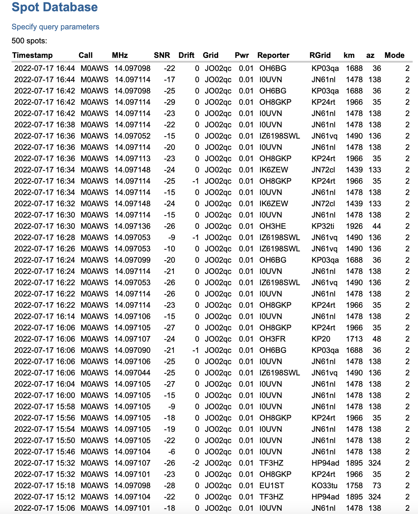
You can also get a more detailed view of reports from the WSPRnet website where you can query the database and create a detailed list of all decodes over a set period of time.
Detailed list of WSPR decodes
Since my EFHW Vertical is resonant on both 20m and 10m I’ll now run it for the next 24hrs on both bands to see what results I get.
More soon …
We use cookies to ensure that we give you the best experience on our website. If you continue to use this site we will assume that you are happy with it.Ok