We have an incredible view of the Aurora this evening here in Suffolk. Here’s a few photos my wife and I have taken in the last hour.


More soon …

Talking to the world one station at a time
We have an incredible view of the Aurora this evening here in Suffolk. Here’s a few photos my wife and I have taken in the last hour.
More soon …
Since I’ve been using my Icom IC-705 on the QO-100 satellite I’ve been getting no end of unsolicited great audio reports with one Op even saying I have the best audio he’s ever heard on the satellite.
Most people are surprised when I tell them that I am using the stock fist mic that comes with the radio. It’s nothing special, in fact it’s rather cheap and plastic, not particularly good quality however, it does seem to have a good sounding mic insert.
The other great thing about the IC-705 is that it has a two channel parametric equaliser built into the radio. Many people don’t realise this and miss out on the massive improvement they can make to their transmitted audio with just a few simple adjustments.
The stock fist mic has a very flat response across the audio frequency range out of the box and doesn’t sound particularly inspiring. Many see this as a negative and often just replace the mic with either a headset (probably from Heil), a boom mic (again probably from Heil) or another, better quality fist mic. All of these options cost varying amounts of money when in reality none of them are necessary.
Starting from a flat audio response is actually a good thing as it makes the equaliser adjustments more pronounced, making it easier to adjust the settings to suit your voice.
We all have different voices but, there is one thing that is pretty much the same for everyone and that’s the frequency range in which the articulation of the words and sounds we make can be found. It’s this part of the voice that is often lacking when we struggle to understand what the DX station is saying.
It’s become common place on the HAM bands these days for stations to boost the bass frequencies and reduce the mid and high frequencies with the net result of a horrible bass ringing sound and muddy mid range often making it very difficult to understand what is being said.
Having spent some considerable time watching the great videos on audio from the late Bob Heil, K9EID it’s clear that the most important frequencies to enhance are those around 2.5khz as this is where all the articulation is in the human voice.
To this end I set about setting up the audio on my IC-705 QRP radio so that my voice sounded such that it is easy to comprehend even in the most difficult of situations on air. This doesn’t mean that it has to be very harsh and overly bright, quite the opposite in that to be heard clearly in all conditions on air one’s audio needs to be balanced across the frequency range with an enhancement in the 2.5Khz frequency range.
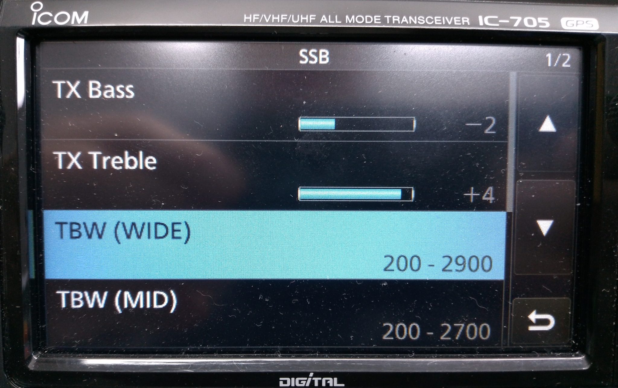
To reduce the unwanted, muddy bass the first thing to do is change the transmit bandwidth for the “Wide” setting to 200-2900Hz. This will cut off the bottom 100Hz from the voice reducing the overall bass output from the standard fist mic that comes with the radio. This will ensure a 2700Hz wide SSB signal, the recommended max for QO-100 operations and the preferred bandwidth on the HF bands.
On top of this I made a further reduction of 2dB on the TX Bass setting to help balance out the overall audio response of the mic insert.
Next I set about enhancing the higher frequency response of the mic insert and found that it required an increase of 4dB to bring out the articulation of my voice. This enhanced my audio considerably compared to the standard output from the fist mic and improved the intelligibility of my voice considerably, especially in difficult band conditions.
To complete the setup I set the compression to 3 and mic gain to 35 so that the overall drive level is increased slightly giving a greater average output from the radio.
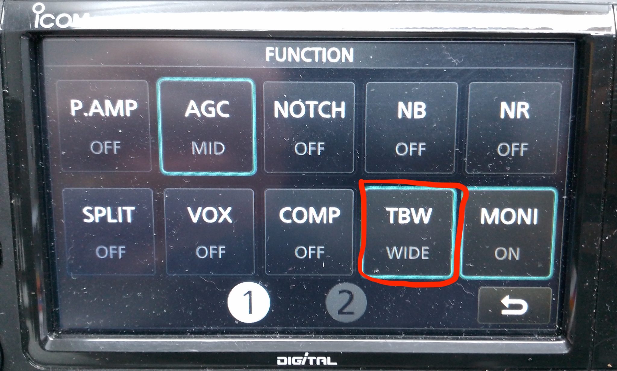
Once I’d got the audio setup correctly I enabled the configuration by setting the Transmit Bandwidth (TBW) to the “Wide” config in the IC-705 Function menu so that the correct settings were made active.
Ever since making these relatively easy changes I have had no end of unsolicited great audio reports from stations asking me what mic I am using and how I’ve managed to get such good audio from the IC-705. Many are surprised that I am using the OEM fist mic that comes with the radio and I’m sure there are those who don’t believe me!
Of course all voices are slightly different and these settings may not be perfect for your voice but, all those that have tried these settings have told me that their audio sounds better than ever and that DX stations often comment on how good their audio is.
I also went through the same exercise with my Yaesu FTDX10 with it’s standard fist mic and again achieved excellent results with it’s 3 channel parametric equaliser. I’ll go through the somewhat more complicated setup for the FTDX10 in another article soon.
I’ve got a couple of old RaspberryPi computers on the shelf in the shack and so decided it was time for me to put one of them to good use. The first model on the shelf is the oldest and is one of the very first RaspberryPi 1 computers that was released. (It’s the one with the yellow analog video signal output on the board!). This particular model is extremely slow but, I hang onto it just as a reminder of the first SBC in the line.
The second one is a RaspberryPi 2, a quad core machine that is only slightly faster than the first model but, it’s powerful enough to run HAM Clock.
It didn’t take long to install a vanilla Raspbian Desktop O/S and get it configured on the local LAN. I installed a few packages that I like to have available on all my Linux machines and then started on the HAM Clock install.
The first thing I needed to do was install the X11 development library that is required to compile the HAM Clock binary. To do this, open a terminal and enter the command below to install the package.
sudo apt install libx11-devYou will need to type in your password to obtain root privileges to complete the installation process and then wait for the package to be installed.
The HAM Clock source code is available from the HAM Clock Website under the Download tab in .zip format. Once downloaded unzip the file and change directory into the ESPHamClock folder ready to compile the code.
cd ~/Downloads/ESPHamClockOnce in the ESPHamClock directory you can run a command to get details on how to compile the source code.
make helpThis will check your system to see what screen resolutions are available and then list out the options available to you for compiling the code as shown below.
The following targets are available (as appropriate for your system)

    hamclock-800x480          X11 GUI desktop version, AKA hamclock
    hamclock-1600x960         X11 GUI desktop version, larger, AKA hamclock-big
    hamclock-2400x1440        X11 GUI desktop version, larger yet
    hamclock-3200x1920        X11 GUI desktop version, huge

    hamclock-web-800x480      web server only (no display)
    hamclock-web-1600x960     web server only (no display), larger
    hamclock-web-2400x1440    web server only (no display), larger yet
    hamclock-web-3200x1920    web server only (no display), huge

    hamclock-fb0-800x480      RPi stand-alone /dev/fb0, AKA hamclock-fb0-small
    hamclock-fb0-1600x960     RPi stand-alone /dev/fb0, larger, AKA hamclock-fb0
    hamclock-fb0-2400x1440    RPi stand-alone /dev/fb0, larger yet
    hamclock-fb0-3200x1920    RPi stand-alone /dev/fb0, huge
For my system 1600×960 was the best option and so I compiled the code using the command as follows.
make hamclock-1600x960It’s no surprise that it takes a while to compile the code on such a low powered device. I can’t tell you how long exactly as I went and made a brew and did a few other things whilst it was running but, it took a while!
Once the compilation was complete you then need to install the application to your desktop environment and move the binary to the correct directory.
make installOnce the install is complete there should be an icon on the GUI desktop to start the app. If like mine it didn’t create the icon then you can start the HAM Clock by using the following command in the terminal.
/usr/local/bin/hamclock &The first time you start the app you’ll need to enter your station information, callsign, location etc and then select the settings you want to use. There are 4 pages of options for configuring the app all of which are described in the user documentation.

Once the configuration is complete the map will populate with the default panels and data. I tailored my panels to show the items of interest to me namely, POTA, SOTA, International Beacon Project and the ISS space station track. I was hoping to be able to display more than one satellite at a time on the map however, the interface only allows for one bird to be tracked at a time.
You can access the HAM Clock from another computer using a web browser pointed at your RaspberryPi on your local LAN using either the IP address or the hostname of the device.
http://<hostname>:8081/live.html
or
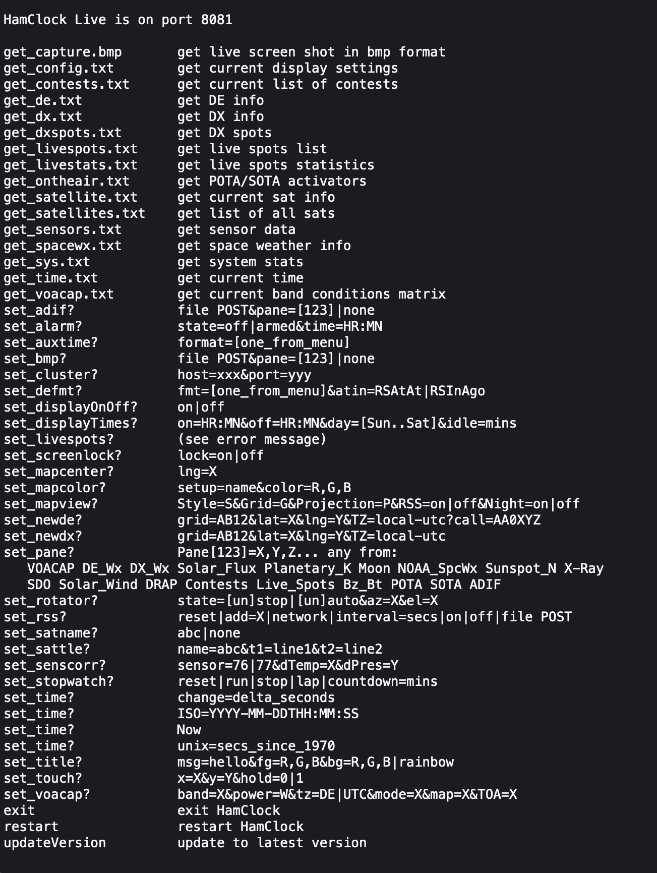
http://<ip-address>:8081/live.htmlYou can also control the HAM Clock remotely via web browser using a set of web commands that are detailed on port 8080 of the device.
http://<hostname or ip-address>:8080/
This is a great addition to any HAM shack especially if, like me you have an old HDTV on the wall of the shack that is crying out to display something useful.
More soon …
After initially finding that I couldn’t tune the 868Mhz ground plane antenna with the radials bent down at 45 degrees I decided to experiment to find out why.
Initially I had the radials connected to the 4 corners of the base of the chassis mount N Type socket. This works great if you have the radials completely horizontal and gives an SWR of 1.1:1 but, with the radials bent down at 45 degrees the best SWR is around 2:1.

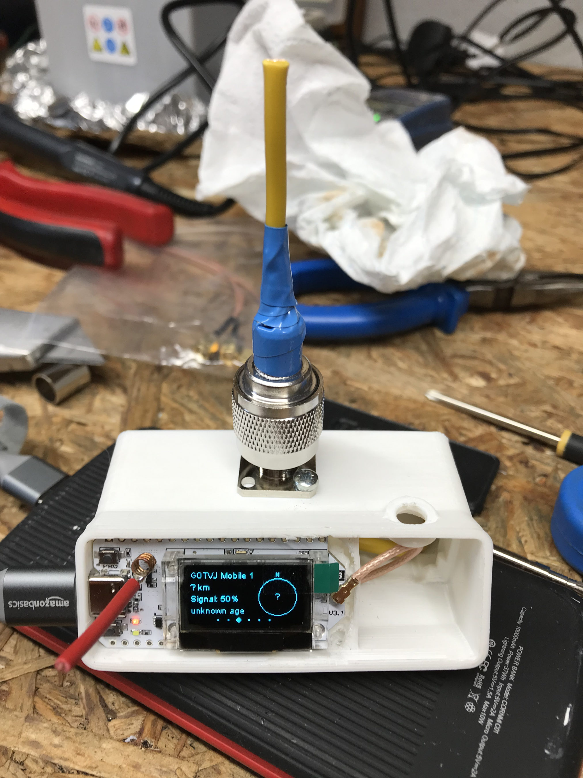
Removing the radials from the base of the N Type chassis socket and soldering them to the outer of the N Type plug at the same level as the feed point for the radiating element I found that an almost perfect SWR can be achieved very easily.

It seemed weird to me that such a small change could have such a big effect on the obtainable SWR for the antenna but, as can be seen in the image below with the radials soldered to the N Type plug and bent downwards I immediately got an SWR of 1.07:1 and a much wider SWR curve.

By making my own antennas I’m learning a lot about antenna design for the 800-900Mhz frequency range. Minor changes seem to have a much bigger impact than they do at much lower frequencies.
More soon …
This is a question I get asked regularly via email and so I decided to post this article so that I can refer to it in future emails.
Callum of DXCommander fame has just published a great video explaining the difference between dBi and dBd that is well worth watching if you don’t understand the difference between the two.
More soon …
In my quest to improve my Meshtastic signal range using home-brew antennas I’ve finally put together a neat little ground plane vertical antenna for the 868Mhz ISM band.
The design follows the normal ground plane simplicity using 4 radials and a vertical radiating element albeit on a tiny scale. The radiating element is 82mm long and the radials are each 92mm long.

Initially I modelled the antenna at a height of 3m above the ground with the radials tilted downwards at 45 degrees. I took this approach as this is how I have built ground plane verticals for the 70cm band in the past and so I thought I’d try the same approach on the 868Mhz ISM band. (I later found this to be detrimental to tuning!)
The 3D far field plot for the antenna shows it has a very nice, relatively high gain lobe at just 2 degrees elevation with a number of lower gain lobes higher up.

Looking at the 2D far field plot you can get a better understanding of the radiation pattern and gain figures at various angles. At 2 degrees there is 6.7dBi gain with the next major lobe being at 8 degrees with 4.36dBi gain, far more than I imagined I’d see for such a simple antenna.

Putting the antenna together was easy enough with particular attention being paid to the measurements of both the radials and radiating element. I soldered some lugs to the ends of the 2.5mm diameter solid core wire radials to enable easy attachment to the N Type chassis socket that I decided to use as the base for the antenna. This worked out well and provided a good solid mechanical and electrical connection for the 4 radials.
For the radiating element I used an N Type plug with the vertical 2.5mm solid core wire element soldered to the inner centre pin of the male connector. I also slid a small piece of insulation down the wire to stop it from shorting against the metal outer of the plug and then pushed in a tight rubber plug to stop water ingress.
Connecting my VNA I found the antenna was mostly resonant at 790Mhz with an SWR of 2.5:1. I knew this would be the case and that the wires would need a little trimming.
Trimming the wires a couple of times in 1mm nibbles I got the point of resonance up to 868Mhz but, the antenna was still exhibiting a lot of reactance that was keeping the SWR above 2:1. Trimming the radials reduced this slightly but, I could not get an SWR much lower than 1.95:1.
Scratching my head I decided to try moving the radials back up so that they were horizontal rather than at 45 degrees downwards, this had the immediate effect of the SWR dropping to 1.1:1.

The SWR stays below 1.2:1 from 868Mhz to 871Mhz which is plenty wide enough for the Meshtastic devices. Why there is so much reactance when the radials are bent down at 45 degrees I am not sure, but it was easy enough to resolve.

The finished antenna is tiny but, seems to work well. Signals from my other nodes are up by 6-9dB according to the SNR reports in the Meshtastic app. I now need to make a couple more of these for my other nodes and then hope to hear some other nodes locally once they appear on air.
Remodelling the antenna in EzNEC with the radials as shown above the gain at 2 degrees is now 5.5dBi, down 1.2dBi but, the overall radiation pattern is identical to the original.
Total cost of the build is about £1 and an hour of my time tinkering with it, bargain!

More soon …
Following on from my last article on improving the Heltec ESP32 v3 antennas I found during the installation of the 90 degree SMA connector that the device was very sensitive to stray capacitance from things around it. After reconnecting my VNA I found the SWR curve would change substantially depending on what the device was near and so I set about rectifying this.
I decided to remove all the insulation from the single radial inside the unit and then added two more radials to increase the ground for the antenna to tune against. I then removed the N type plug with the antenna connected to it and made a new antenna from a piece of 1.5mm solid core insulated mains wire connected directly to the N type socket, without using an N type plug. Tuning to resonance was much easier than before and I soon had the SWR down to 1.2:1. Moving the device around and placing near to other objects the SWR curve was now much more stable than before with only very slight changes in curve shape.

Making this change to the 868Mhz antenna has shown an improvement in signal strength from my node-1 device of almost +0.5dB, every dB counts when you only have 100mW to play with!
The Bluetooth antenna update has made a massive improvement to the usability of the device via the iOS Meshtastic app. Being able to have a reliable, solid connection from anywhere in the house is great and I no longer lose messages because I’ve strayed outside the range of the Bluetooth connection.
I now have 2 new Heltec ESP32 v3 devices on the way to me and will be getting those configured and operational outside with external antennas in the hope of hearing some nodes locally to me.
More soon …
The Heltec ESP32 v3 LORA devices have a coil type Bluetooth/Wifi antenna on the PCB from the factory. This antenna doesn’t work particularly well and has very limited range so, I decided to do something about it.
Getting out the calculator a quarter wave at 2400Mhz is 29.7mm. Looking at the coil antenna on the PCB I decided the best way to connect the new antenna would be to solder it to the coil of the existing antenna. This would short out the coil completely whilst creating a solid mount point for the new antenna.
After a little measuring I decided to use a 31mm long piece of 1.5mm hard core mains cable for the new antenna. I stripped back the insulation from one end of the wire so that the exposed copper wire was exactly the length to short across all the windings of the coil antenna on the PCB.

Attaching the the wire to the coil was easy enough to do but, it’s worth pointing out that you need to be quick so that the heat doesn’t transfer down onto the PCB desoldering the coil antenna from the device.
Whilst tinkering with the Bluetooth antenna I decided I would also make a neat little quarter wave 868Mhz vertical antenna for this device whilst I had it all apart. This is my Meshtastic node-2 and it’s sole purpose is to allow me to use my iPad to send/receive messages via bluetooth which are then forwarded on to my base node-1 in the house. Node-1 is connected to the house wifi and the Meshtastic MQTT server. This combination allows me to message people on the mesh even though there are no local nodes within RF range.
Running the numbers for the 868Mhz antenna the vertical will need to be around 82.1mm long with a radial of similar length. I had to hand a very nice SMA to N Type chassis mount socket that would be ideal to mount the antenna to the case. I drilled out the holes in the case, measured out the wires and attached it all to the case. Connecting the antenna to the N Type socket I connected my VNA and set about tuning the antenna to resonance.

Squeezing the radial and SMA connector into the case I realised I really could do with a 90 degree SMA connector so, I quickly ordered one from Amazon which will be delivered tomorrow. Connecting up my VNA, I had to trim the antenna down to get it to resonance. The SWR ended up at 1.2:1 which is ideal. I ended up cutting off more wire than I thought I would to get the antenna to resonance but, this is due to the extra capacitance caused by the insulation on the wire. If I had used bare copper wire then I wouldn’t of had to cut so much off. I eventually ended up with around 72.9mm of wire for both the antenna and radial.
Putting the device back into the case and connecting the USB battery the device fired up and immediately connected to my node in the house. Checking the signal strength of node-1 in the house I could see a 7dB increase in signal strength compared to the little wire antenna that comes with the device. This is a significant improvement for such a simple antenna and well worth the effort.
Next I had to drill a hole in the front of the Heltec case so that the Bluetooth antenna could poke out the front and be bent up vertically. This worked out really well and improved the Bluetooth range massively.

Putting the node back in the house and taking my iPad down to the end of the garden some 30m away I could instantly connect to the device via Bluetooth from my iPad, something I’d not been able to do prior to adding the new antennas. I can now use the Heltec device via Bluetooth from anywhere in the house or garden making it much more accessible.
It’s amazing the difference an hour and two little pieces of wire can make to these devices and is well worth the effort.
More soon …
The loading of the Meshtastic firmware on the Heltec ESP32 v3 devices is really simple if done via a Linux PC/RaspberryPi. There are of course other ways to load the firmware using a web browser that supports USB/Serial devices and this method is preferred by many however, being a Linux command line junkie I far prefer the simplicity of using the Linux command line to do the job.
So, how much experience with the Linux command line do you need?
In all honesty none at all. If you know how to use copy and paste then all you have to do is follow the simple steps I’ve detailed below. In reality it will only take a few minutes to do so, don’t be put off by the long article, I’ve just tried to cover everything and provide screen shots along the way.
To get started fire up your Linux PC/RaspberryPi and get yourself to the desktop. Next you will need to open a Linux command line terminal. This is often just called “Terminal” on most Linux desktop installations.
The first thing you need to do is check to see if you have python3 installed. This is done using the following command:
python3 --versionRunning the above command you should see a result something like what is shown below.

Next we need to check if pip3 is installed using the following command:
pip3 --versionIf pip3 is installed then you should get a result similar to that shown below.

If your computer doesn’t have Python3 or Pip3 installed they can be easily installed from the command line. To install Python3 enter the following command into your terminal:
sudo apt install python3You will be asked to enter your login password and then the installation will begin. You should see output in your terminal similar to that shown below.

To install Pip3 enter the following command into your terminal:
sudo apt-get install python3-pipThis will detail a long list of packages that will be installed on your computer, Enter Y to answer Yes and let the packages install.

You will see many messages scroll up the terminal screen such as getting, selecting, preparing, unpacking and setting up, this is all normal.
Once Pip3 is installed you should be dropped back at the command line with a terminal screen that looks something like the one below.

At this point you will now have Python3 and Pip3 available on your computer.
You are now ready to install the tool we are going to use to check your Meshtastic device is connected to your PC and install the firmware to it. (Do not connect your Meshtastic device to your PC just yet!)
Run the following command in your terminal to install the ESP Tool:
pip3 install --upgrade esptoolYou will see an output from the installation process similar to that shown below.

Now that we have the ESP tool installed plug your Meshtastic device into your USB port on your computer and then run the following command to interrogate the device to find out what kind of device it is.
esptool chip_idYou should see the information about your device that looks similar to that shown below. This information should confirm the device type (ESP32) and which USB port it is connected on (/dev/tty/USB0).

Once you have this information you will need to download the firmware for your device from Github using the following URL:
https://github.com/meshtastic/firmware/releasesAt the time of writing this I downloaded and used the v2.2.22.404d firmware which I have found to be extremely reliable.
In your terminal you now need to change directory (cd) into the Downloads directory where your downloaded firmware should be. (If you downloaded your firmware into another directory then you will need to cd into that directory). Use the following command to change directory into the Downloads directory.
cd ~/DownloadsNow we need to find the filename of the firmware we have just downloaded, we can use the list directory contents command to find the file using the simple command below.
ls -la firm*.zip
In the screenshot above we can see that the filename is called
firmware-2.2.22.404d0dd.zip.
We now need to unzip the file using the unzip command.
unzip firmware-2.2.22.404d0dd.zipYou’ll see lots of output from the unzip command about inflating files etc, this is normal.
Once the file has been unzipped you are ready to load the firmware onto your Heltec device. First you need to find the .bin file for your Heltec device. Use the following ls command to list the files available.
ls -la firmware-heltec*This will list out all the firmware file options for the Heltec device as shown below.

The file you need to use for a new firmware installation on a Heltec v3 device is
firmware-heltec-v3-2.2.22.404d0dd.bin. (If you downloaded a different version then the version number in the file will be different).
Using the filename you found above enter the following command into your terminal.
./device-install.sh -f firmware-heltec-v3-2.2.22.404d0dd.binThis will now clear down your Heltec device and will load the Meshtastic firmware. This will take a little time especially on slower computers like the RaspberryPi so, just let it run until it finishes. Do not interrupt the process whilst it is running.

Once the firmware is loaded the Heltec device will reboot and you will see the Meshtastic banner on the OLED screen. Your device is now ready for configuration.
Now that you have Python3 and Pip3 installed you can load the firmware onto other devices just by downloading the firmware and then running the device-install.sh script file, you won’t need to install Python3 or Pip3 again.
If you want to update your device in the future to a newer version of the firmware then just use the update script and update binary file as shown below.
./device-update.sh -f firmware-heltec-v3-2.2.22.404d0dd-update.binThat’s it, you are now a Linux Command line junkie!
More soon …
Meshtastic is a relatively new thing in the internet of things (IOT) world and is gaining traction in the U.K. at the moment.
So what is Meshtastic?
Meshtastic is an open source, off-grid, decentralised mesh network built to run on affordable, low-power devices on the 868Mhz industrial, scientific, and medical (ISM) band. (Some devices can also run on the 433Mhz 70cm HAM band.)
The ISM band is licence free but, has limits on the RF power levels that can be used. The one plus over the HAM bands is that you can legally transfer encrypted messages over the ISM band making it secure.
The best way to think of Meshtastic is a radio version of the online decentralised Matrix chat system but, without the large server requirements and ever growing database!

There are quite a few Meshtastic compatible devices on the market today with many costing around the £20 mark whilst others like the LillyGo T-Echo costing over £100 in the U.K. even though they are less than half the price in the USA.
Since I’m just starting out on my Meshtastic adventure I thought I’d start with a pair of Heltec ESP32 v3 devices that are normally readily available on Amazon but, due to the current push to build a U.K. wide mesh, they are currently out of stock pretty much everywhere.
Loading the Meshtastic firmware onto the devices is fairly straight forward and can be done using the web installer via either the Edge or Chromium web browsers.
(Note: If using Windows O/S you will need to install some drivers from the Meshtastic website to be able to communicate with the devices)
Having neither of the two browsers and being a Linux command line junkie I decided to use the Python programme to load the firmware onto the two devices. It’s worth noting that you don’t need any drivers to be able to communicate with the devices if you’re using either Debian or one of the many Ubuntu flavours of Linux O/S.
Using the Python command line program sounds like a more complicated approach but, in reality it’s super simple, extremely reliable, quick and if like me you use a Linux PC in the radio shack then you most likely already have most of what you need to get the job done. Just follow the simple steps as laid out on the Meshtastic web site and you’ll have the firmware loaded in no time at all.
The firmware takes less than a minute to copy across to the Heltec device and is automatically rebooted ready for configuration once the transfer has completed.
It is possible to configure the device via the command line tool however, since there is a nice GUI app for both Apple iOS and Android devices I decided to install the Meshtastic app on my iPad and connect to the device via Bluetooth to configure it.
Once you’ve got the Meshtastic app installed on your device and have connected via Bluetooth you’ll be ready to start configuring the device to join the mesh. The first thing you want to do is set the region. This is different in each country but, in the UK we use the EU_868 region settings. This will set the device to use the 868Mhz ISM band which is the band being used to build the U.K. wide mesh.

There is a multitude of configuration options within the app which I will go into in greater detail in a series of articles at a later date.

For those of you that, like me aren’t near any other nodes you can connect the devices to the internet and use the Meshtastic MQTT server to communicate with other nodes. This of course isn’t off-grid but, it will get you started until the mesh grows into your local area at which point your device will automatically start communicating with the other nodes over radio.

Once you are connected to either the MQTT server or other nodes via radio you will see the other node details appear in the Meshtastic app. It’s interesting to look at the information and see signal strengths and traffic levels etc for each node.

There are a multitude of cases available for the Heltec v3 devices, especially if you have access to a 3D printer. One of the nicest cases I have seen is the Bender from IKB3D (I know, it’s a strange name!) but, it really is a super little case for the Heltec series of devices.


You can either buy the 3D print files for £8.99 and print it yourself or just order a pre-printed and assembled case directly from the website although, due to demand there is a long lead time currently.
More soon …