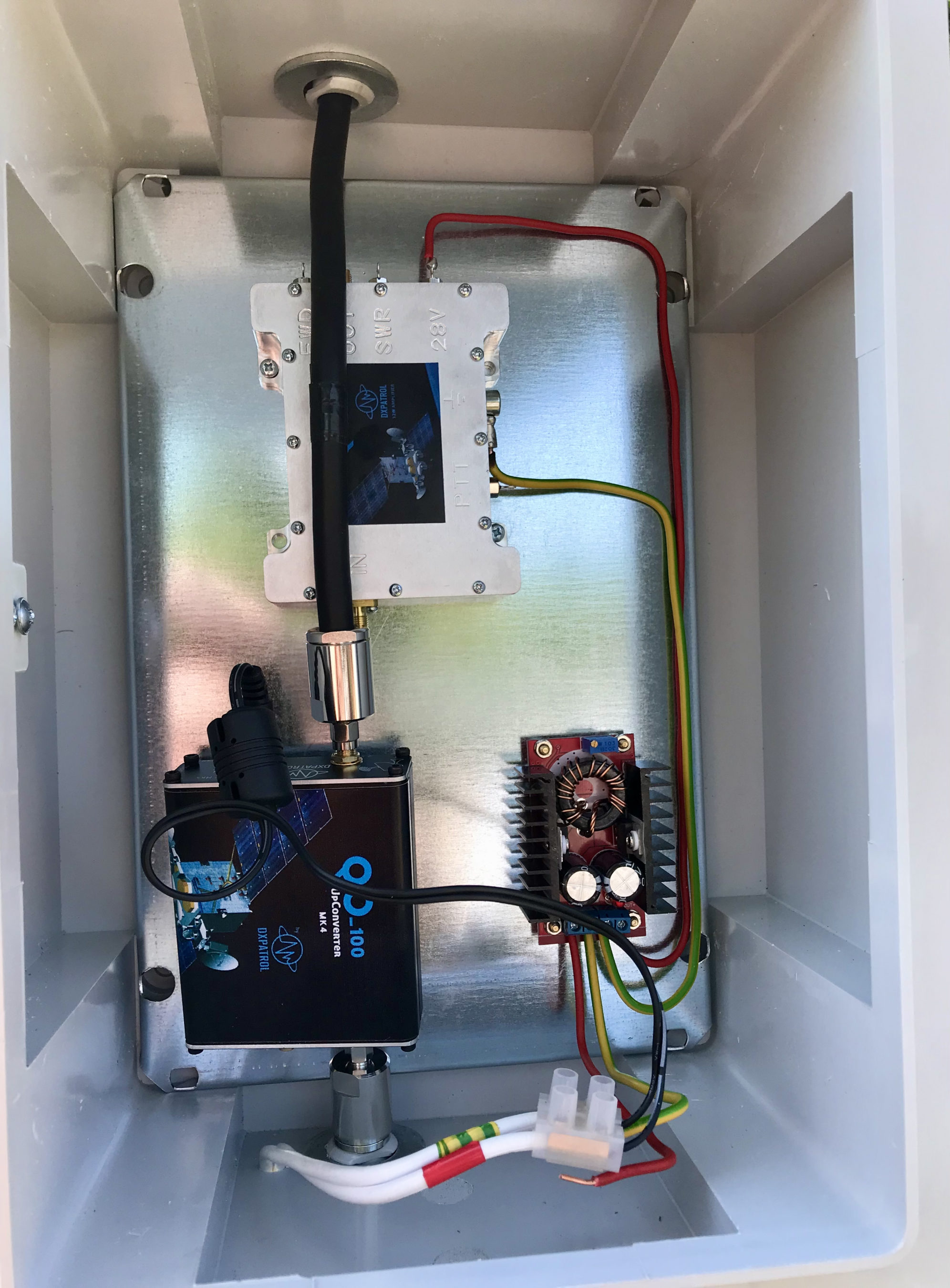
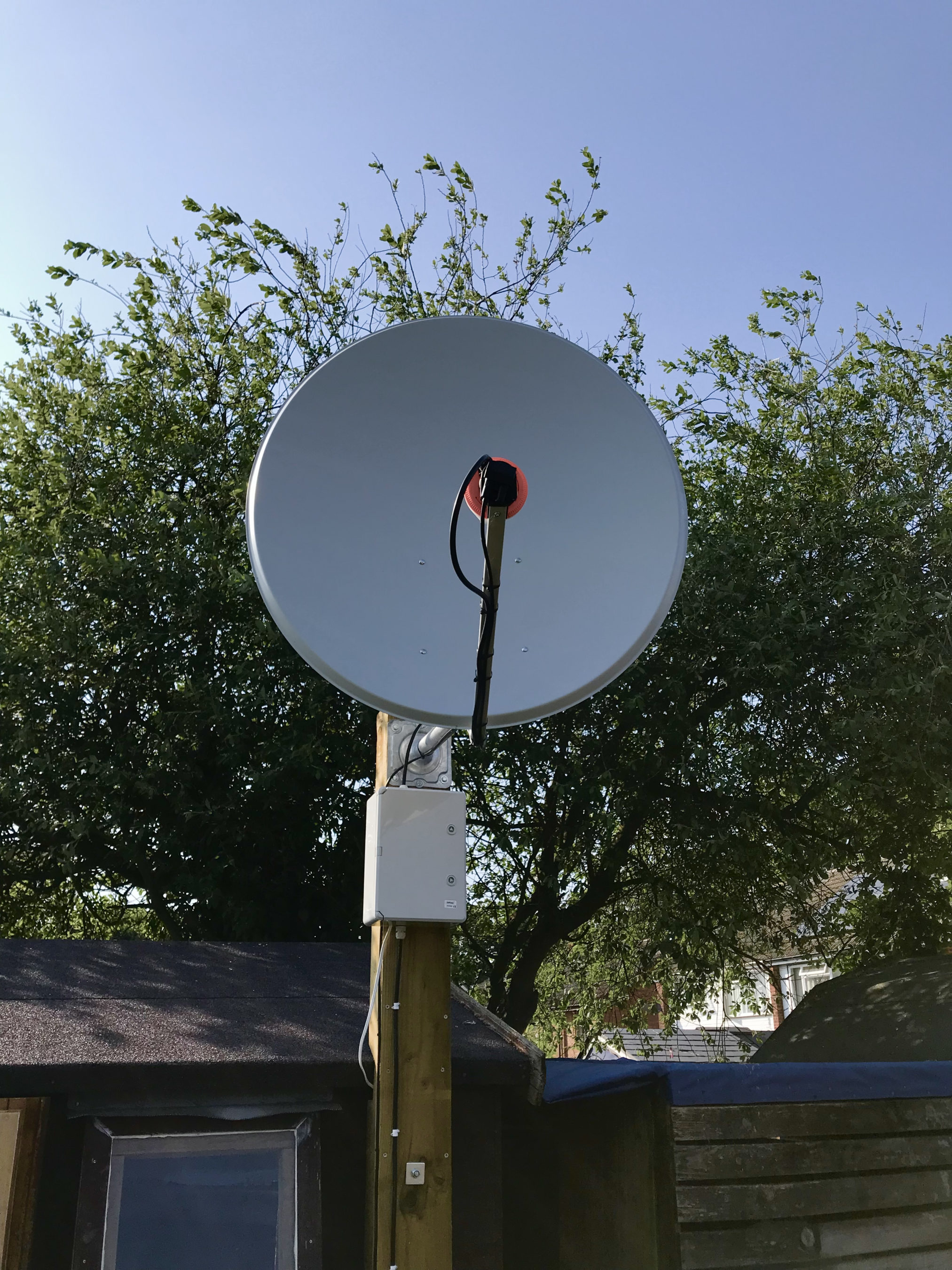
I’ve been waiting for over a week so far for a male to male SMA connector to arrive from Amazon so that I can connect the 2.4Ghz up-converter to the 2.4Ghz amplifier. Since it still hasn’t arrived I decided to connect the up-converter directly to the IceCone Helix antenna to see if I could get a signal into the QO-100 satellite.
To my surprise I could easily hear my CW signal on QO-100 even though the total output from the up-converter is only 200mW.
I didn’t expect to be able to hear my signal since it’s a tiny amount of power that has to travel some 22500 miles to the satellite but, I could hear it and was amazed that it was peaking S8 on my SDR receiver.
2.4Ghz Up-Converter connected directly to the antenna bypassing the 2.4Ghz Amplifier
Being excited I put out a CQ call that was soon answered by OH5LK, Jussi in Finland. Jussi gave me a 579 report which I was extremely pleased with. He was of course much stronger at a 599+ at my end. We had a quick QSO and exchanged details without any problems at all. Its really nice to get a QRPp contact without any QSB or QRM.
M0AWS QO-100 1.1m off-set Dish and IceCone Helix antenna ground station
Neil, G7UFO who I chat with regularly in the Matrix Amateur Radio Satellites room has posted a connector out to me so I’m hoping it will arrive on Monday and then I’ll be able to connect the amplifier and hopefully get a few SSB contacts.
UPDATE: I’ve since had 2 SSB contacts via QO-100 using just the 200mW O/P from the up-converter. Both times I got a 3/3 report not brilliant but, perfectly acceptable for the amount of power I’m putting out.
For some time now I’ve been using my Funcube Dongle Pro+ (FCD) as my QO-100 downlink receiver. It’s worked fairly well and has given me the ability to listen to stations on the satellite over the last few months.
During this time I have noticed a couple of things about the FCD that has lead me to the final decision to change to a new SDR device.
The first of these ‘things’ is the fact that the FCD gets seriously overloaded when there are multiple large SSB signals within the receive pass band. The only way to manage this is to constantly keep changing the software based AGC, mix and LNA settings to reduce the levels of the incoming signals so that the overloading stops. This is great except when you tune to a quiet part of the satellite transponder you have to turn all the settings back up again to be able to hear the weaker signals. After a while this becomes tiresome.
The fact that there isn’t a hardware AGC in the FCD is a major drawback when being used for satellite reception especially when it’s on the end of a very high gain LNB and dish antenna.
The second of these ‘things’ is the fact that I can’t see the whole transponder bandwidth at one time with the FCD as it has a very small receive bandwidth capability. This means that I am constantly tuning up and down the transponder to see if there are any stations further up or down in frequency.
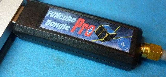
Funcube Dongle Pro+
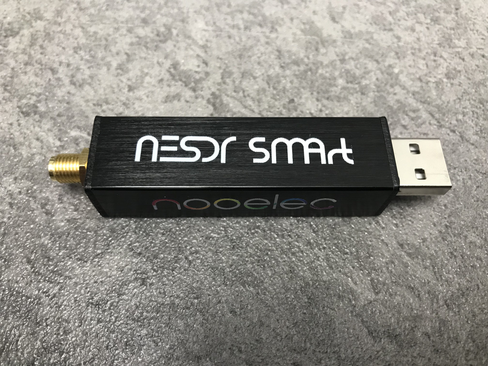
Talking to more experienced satellite operators in the Matrix Amateur Radio Satellites room they recommended replacing the FCD with a NooElec NESDR SMArt v5 that has hardware AGC and is capable of receiving and displaying a much wider bandwidth.
Looking on Amazon the NooElec NESDR SMArt v5 is only £33 so I decided to place an order for one and give it try.
In typical Amazon style the SDR receiver arrived the next day and I wasted no time getting it plugged in and connected to the QO-100 ground station.
The NESDR SMArt v5 is based on the well known RTL-SDR that came onto the market some time back but, has a number of improvements in it that take it to the next level.
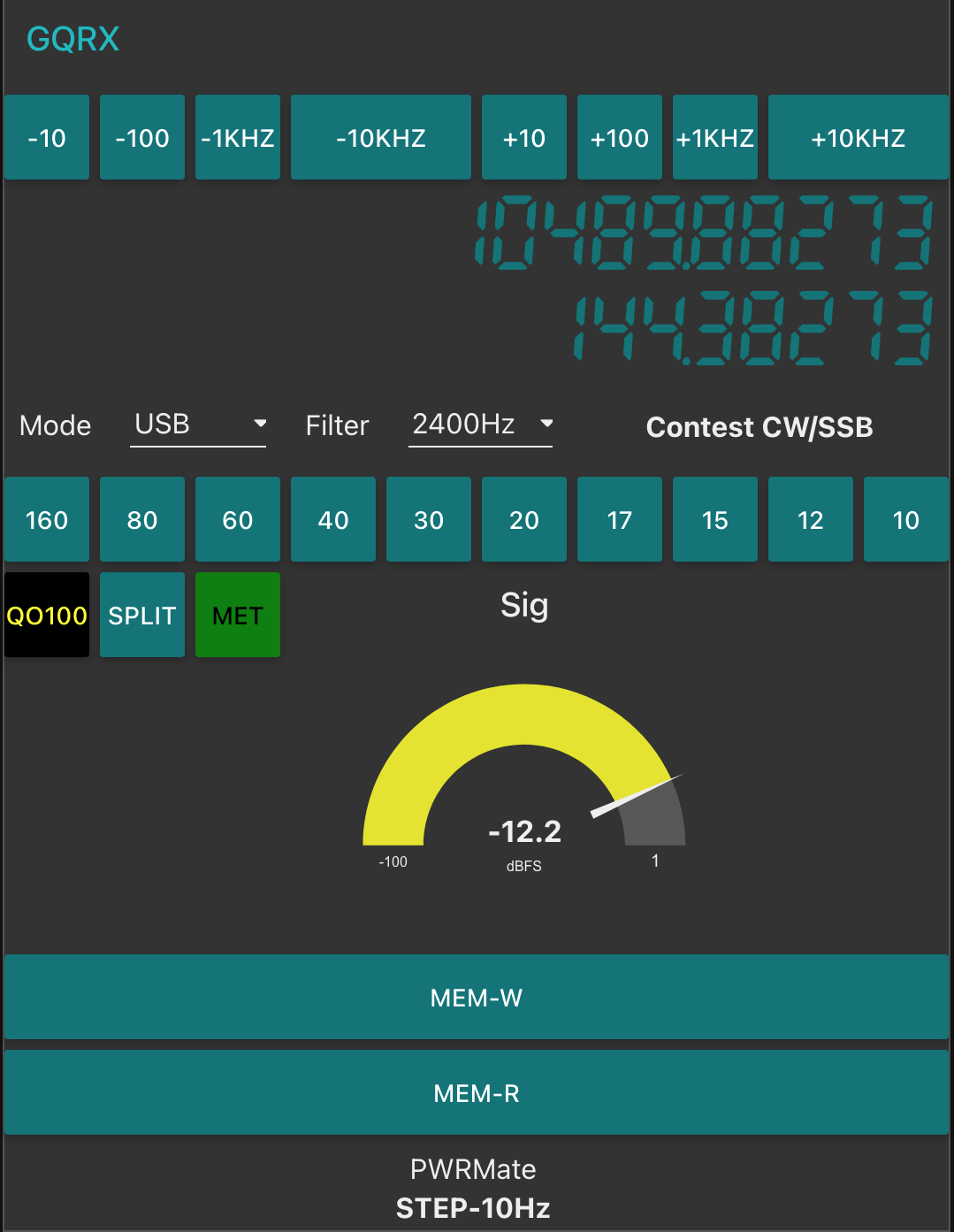
The first thing that I was happy with was the fact that the GQRX SDR software I use recognised it immediately on startup, no configuration or drivers were required it just worked, straight out of the box. Since I use Kubuntu Linux on my radio room PC I did wonder if I would need to get into installing extra libraries etc but, thankfully none of that was required.
Looking at the signals from the QO-100 satellite initially they appeared to be nowhere near as strong as they were on with the FCD. Looking at the settings in GQRX I noticed that the hardware AGC was off and the LNA setting was back to it’s default very low level.
I switched on the AGC and then increased the LNA setting to 38.4dB and found that the signals were now plenty strong enough on the display but, not overloading the receiver.
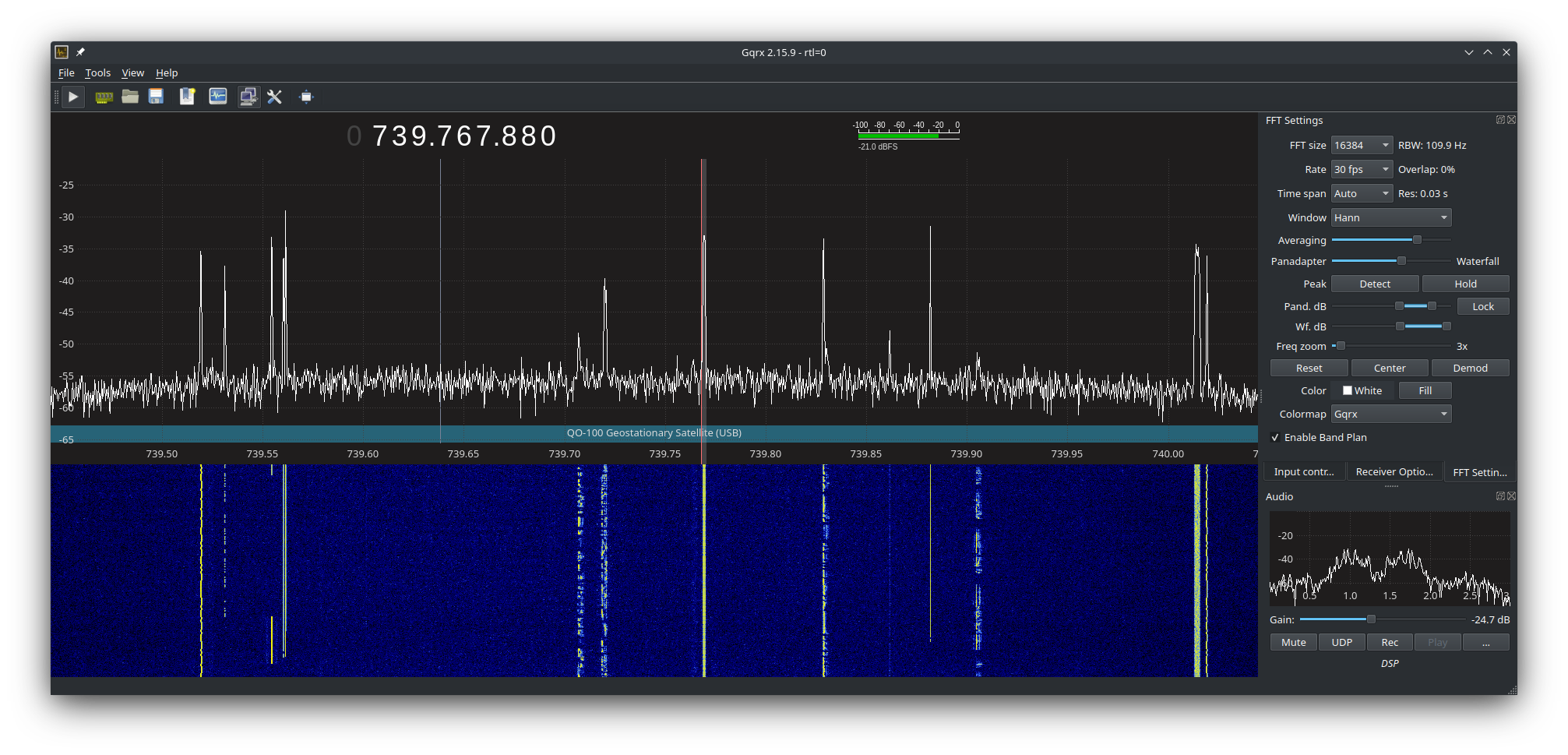
I then went on to adjust the display so that I could see the whole satellite transponder bandwidth on the screen. This is great as it enables me to see the low, middle and high beacons that mark out the narrow band section of the transponder and at a glance see all the stations using the satellite. This was a massive improvement in itself and one that I am very pleased with.
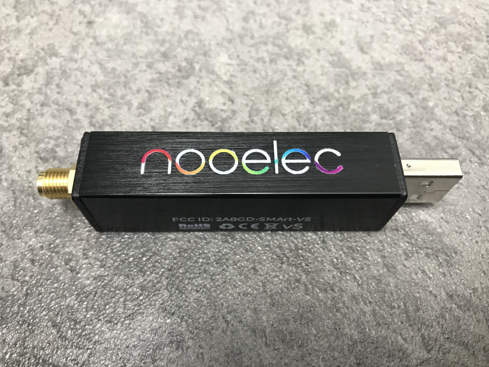
NooElec v5 SDRNooElec v5 SDR
Using the NooElec NESDR SMArt v5 SDR it very soon became clear that it copes with multiple large signals in the pass band so much better than the FCD did. There’s no more overloading of the receiver, no more ghost signals appearing on the waterfall due to the front end not being able to cope and no more having to constantly keep playing with the settings to get things under control. The hardware AGC built into the SDR device does a great job at keeping it all under control whilst receiving a much wider bandwidth than the FCD ever could.
The satellite beacons are now received at S9+15dB without the receiver being overloaded, the first time I have seen this since starting out on my QO-100 venture.
The other thing that became obvious very quickly is that frequency stability is much better than it was with the FCD, it doesn’t drift up and down the transponder now and stays tuned exactly where I put it. It’s also on frequency whereas, the FCD was always 1.7Khz off frequency.
GQRX showing QO-100 Transponder signals
The NooElec NESDR SMArt v5 is very well put together, it has an aluminium case that acts as a heatsink (it does get warm!) and overall the build quality is much better than the plastic cased FCD. When I think that I paid close to £100 for the FCD and the NooElec NESDR SMArt v5 only cost £33, I am amazed at the build quality.
Overall I’m extremely pleased with the purchase of the new SDR, it slotted in perfectly as a replacement for the FCD, works great with GQRX, my QO-100 Node Red Dashboard and performs considerably better than the FCD. Overall money well spent!
You can find the NooElec NESDR SMArt v5 spec sheet here.
I’ve been gradually building my QO-100 ground station over the last few months and have had the receive path working for some time now. One of the things I really miss with the Funcube Dongle Pro+ (FCD) SDR is a real VFO knob for changing frequency.
My QO-100 Node Red dashboard is configured so that I can have the FCD track the uplink frequency from the IC-705 but, sometimes I use the FCD without the IC-705 in the shack and so a physical VFO would be handy.
Many years ago when I lived in France (F5VKM) I had a Flexradio Flex-3000 SDR, a great radio in it’s time and one that gave me many hours of enjoyment. One addition I bought for that station was a Griffin Technology Powermate VFO knob. It worked extremely well with the PowerSDR software for the Flex-3000 and I used it for many years.
Many years later I’m back in the UK and much of my equipment is packed away in the attic, including the Griffin Technology Powermate VFO.
I decided to dig it out and see if I could get it working with GQRX SDR software. Sadly I couldn’t get it working with GQRX however, I did find a way of getting it working with Node Red and thus could add it to my QO-100 Node Red Dashboard and then control GQRX with it via a simple Node Red flow.
Griffin Technology Powermate VFO
Plugging the Powermate VFO into my Kubuntu PC it wasn’t immediately recognised by the Linux O/S. After a little searching I found the driver on Github. I added the PPA to my aptitude sources and installed the driver using apt.
Once installed the default config for the Powermate device is to control the default audio device volume. To make the device available for use as a VFO knob you need to change the configuration so that the default setting is disabled. To do this is relatively easy, just edit the config file using your favourite command line editor (Vi/Vim in my case) and add the following entry.
vi /etc/powermate.toml

# Entry to control HDMI volume with Powermate
#sink_name = "alsa_output.pci-0000_01_00.1.hdmi-stereo"

# Set powermate not to work with volume control
sink_name = ""
As shown above, comment out the default “sink_name” entry (Yours may be different depending on audio device in your PC) and add in the Powermate “sink_name” entry that effectively assigns it to nothing.
Once this is done, save the file and exit your editor and then reboot the PC.
Next you’ll need to install a small program called evtest.
sudo apt install evtest
To check the evtest program has installed correctly, plugin your Powermate VFO to any available USB port and run the following command in a terminal.
evtest /dev/input/powermate
Turning the Powermate knob you should see output on the screen showing the input from the device. You should also see BTN events for each press of the Powermate device.
Input driver version is 1.0.1
Input device ID: bus 0x3 vendor 0x77d product 0x410 version 0x400
Input device name: "Griffin PowerMate"
Supported events:
  Event type 0 (EV_SYN)
  Event type 1 (EV_KEY)
    Event code 256 (BTN_0)
  Event type 2 (EV_REL)
    Event code 7 (REL_DIAL)
  Event type 4 (EV_MSC)
    Event code 1 (MSC_PULSELED)
Properties:
Testing ... (interrupt to exit)
Event: time 1685816662.086666, type 2 (EV_REL), code 7 (REL_DIAL), value -1
Event: time 1685816662.086666, -------------- SYN_REPORT ------------
Event: time 1685816662.318638, type 2 (EV_REL), code 7 (REL_DIAL), value -1
Event: time 1685816662.318638, -------------- SYN_REPORT ------------
Event: time 1685816662.574615, type 2 (EV_REL), code 7 (REL_DIAL), value -1
Event: time 1685816662.574615, -------------- SYN_REPORT ------------
Event: time 1685816663.670461, type 2 (EV_REL), code 7 (REL_DIAL), value 1
Event: time 1685816663.670461, -------------- SYN_REPORT ------------
Event: time 1685816664.030421, type 2 (EV_REL), code 7 (REL_DIAL), value 1
Event: time 1685816664.030421, -------------- SYN_REPORT ------------
Event: time 1685816664.334389, type 2 (EV_REL), code 7 (REL_DIAL), value 1
Event: time 1685816664.334389, -------------- SYN_REPORT ------------
Event: time 1685816665.334255, type 1 (EV_KEY), code 256 (BTN_0), value 1
Event: time 1685816665.334255, -------------- SYN_REPORT ------------
Event: time 1685816665.558230, type 1 (EV_KEY), code 256 (BTN_0), value 0
Event: time 1685816665.558230, -------------- SYN_REPORT ------------
Event: time 1685816666.030161, type 1 (EV_KEY), code 256 (BTN_0), value 1
Event: time 1685816666.030161, -------------- SYN_REPORT ------------
Event: time 1685816666.182151, type 1 (EV_KEY), code 256 (BTN_0), value 0
Event: time 1685816666.182151, -------------- SYN_REPORT ------------
At this point you’re ready to stop evtest (CTRL-C) and then create the following little BASH shell script that Node Red will run to collect the O/P from the Powermate USB device.
#!/bin/bash

###############################################
# Griffin Technology Powermate control script #
# for Node Red.                               #
#                                             #
# 04/06/23 - M0AWS - v0.1                     #
#                                             #
###############################################

VAL="1"
echo "STEP-1Hz"

/usr/bin/evtest /dev/input/powermate | while read LINE
do
   case $LINE in

      *"(REL_DIAL), value 1") echo "$VAL"
           ;;

      *"(REL_DIAL), value -1") echo "-$VAL"
           ;;

      *"(BTN_0), value 1") case $VAL in

                              "1") VAL="10"
                                   echo "STEP-10Hz"
                                      ;;

                             "10") VAL="100"
                                   echo "STEP-100Hz"
                                      ;;

                             "100") VAL="1000"
                                    echo "STEP-1Khz"
                                       ;;

                             "1000") VAL="10000"
                                     echo "STEP-10Khz"
                                         ;;

                             "10000") VAL="1"
                                       echo "STEP-1Hz"
                                          ;;
                              esac
                                 ;;
        esac
done
Once the BASH script is copied and pasted into a file called powermate.sh you need to make it executable by using the following command.
chmod 700 ./powermate.sh
If you now run the shell script in a terminal you’ll see a similar output to that shown below from the device when used.
As you can see above the shell script outputs a positive or negative number for VFO tuning and changes the VFO step size each time the Powermate is depressed.
Getting this output from the BASH shell script into Node Red is really simple to achieve using just 3 or 4 nodes.
In the Node Red development UI create the following nodes.
Griffin Powermate Node Red Nodes
The first node in the flow is a simple inject node, here I called it trigger. This sends a timestamp into the next node in the flow at startup to set the flow running.
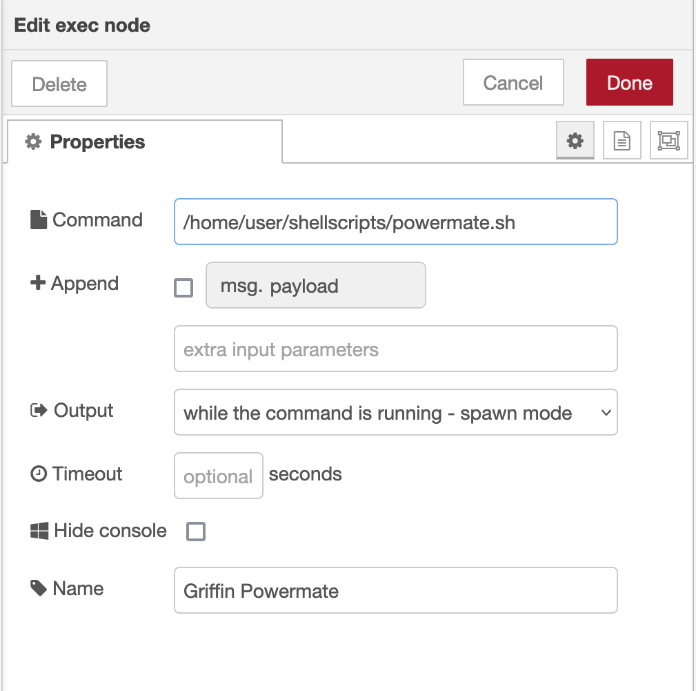
The Griffin Powermate node is a simple exec node that runs the script we created above.
M0AWS Powermate exec node
Configure the node as shown above and connect it to the inject node that’s used as a trigger. Note: Change “user” in the Command field shown above to that of your username on your Linux PC)
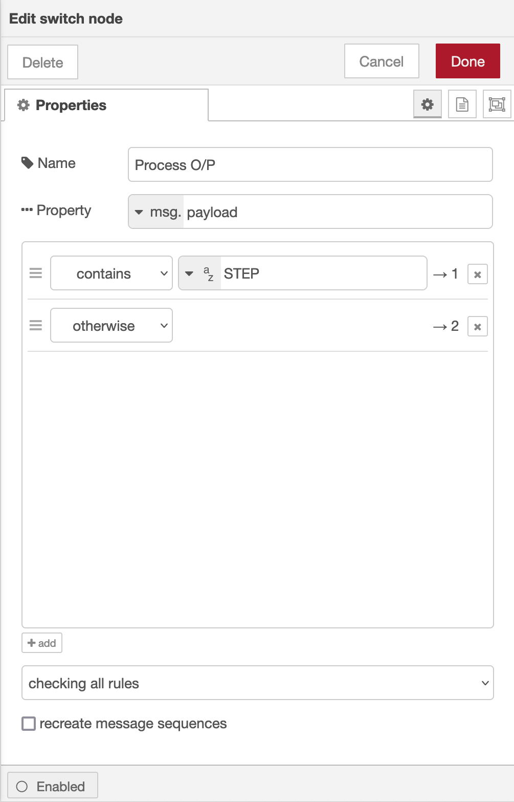
Once done create the third node in the flow, a simple switch node and configure as shown below.
Switch Node for Powermate
The switch node has two outputs, the top one is a text output that is fed into a text field to show the current step size of the Powermate device and the lower output is the numeric output that must be fed into your VFO control flow so that the VFO value is incremented/decremented by the amount output by the Powermate device.
I’ve found the Griffin Technology Powermate USB device works extremely well with Node Red and GQRX that I use for controlling the FCD SDR radio and it’s now part of my QO-100 ground station build.
M0AWS QO-100 Dashboard with Powermate Step Display at bottom
As shown above you can see the Powermate Step size at the bottom of the dashboard, this text changes each time the Powermate device is depressed and will set a step size of 1Hz, 10Hz, 100Hz, 1Khz, 10Khz in a round-robin fashion.
The next stage of the build is the 2.4Ghz transmit path. I now have all the necessary hardware and so this part of the build can finally commence.
The bi-directional slot fed HF antenna isn’t mentioned very often these days for some strange reason. It’s a real shame as it is an excellent antenna that gives high gain through the loop between the frequencies of 14Mhz and 29Mhz.
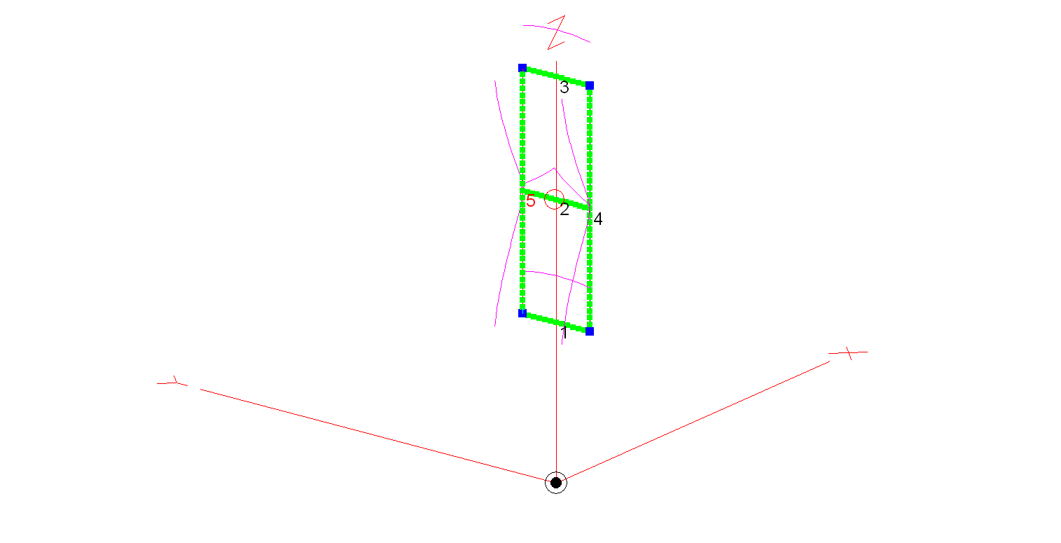
M0AWS 20m – 10m Slot Fed HF Antenna
Construction of the antenna is relatively simple, 3 x 3m long horizontal wires and 2 x 9.2m long vertical wires. I’ve modelled the antenna using 20mm diameter copper tubing for the horizontal conductors and 2.5mm wire for the two vertical conductors. Using the 20mm copper tubing provides a rigid platform for the mounting of the antenna on a non-conductive mast whilst reducing weight by using 2.5mm wire for the vertical conductors. You could of course use 20mm copper tubing for all the conductors if you have a non-conductive mast that can handle the weight.
An alternative option is to hang the antenna from a high tree and secure it in position with non-conductive nylon cord. This works very well and makes it extremely easy to manually rotate.
The antenna is fed at the centre of the middle horizontal tube (conductor 2 in the image above) using one of the following methods:
Method 1 – Use a 4:1 Balun and ATU either in the radio/Radio Shack or connected directly to the Balun. Connecting a remote auto ATU to the balun directly at the feed point is the best option as you will then have a perfect 50 Ohm impedance match to the coax cable going back to the radio. (I’ve used my AH-705 and a 4:1 Balun at the feed point in the past with excellent results).
Method 2 – Connect a remote auto ATU directly to the feed point of the antenna and then 50 Ohm coax back to the radio shack. This will provide a perfect SWR match on all bands and works extremely well. (I’ve used my AH-705 remote auto ATU in this configuration as well in the past, again with excellent results and no discernible difference to method 1).
Method 3 – Feed the antenna with 450 Ohm open ladder line and use a 4:1 Balun and ATU in the radio shack to match the antenna to 50 Ohm radios. It’s important to bring the 450 Ohm ladder line away from the feed point horizontally and not vertically downwards. This will then help to protect the radiation pattern.
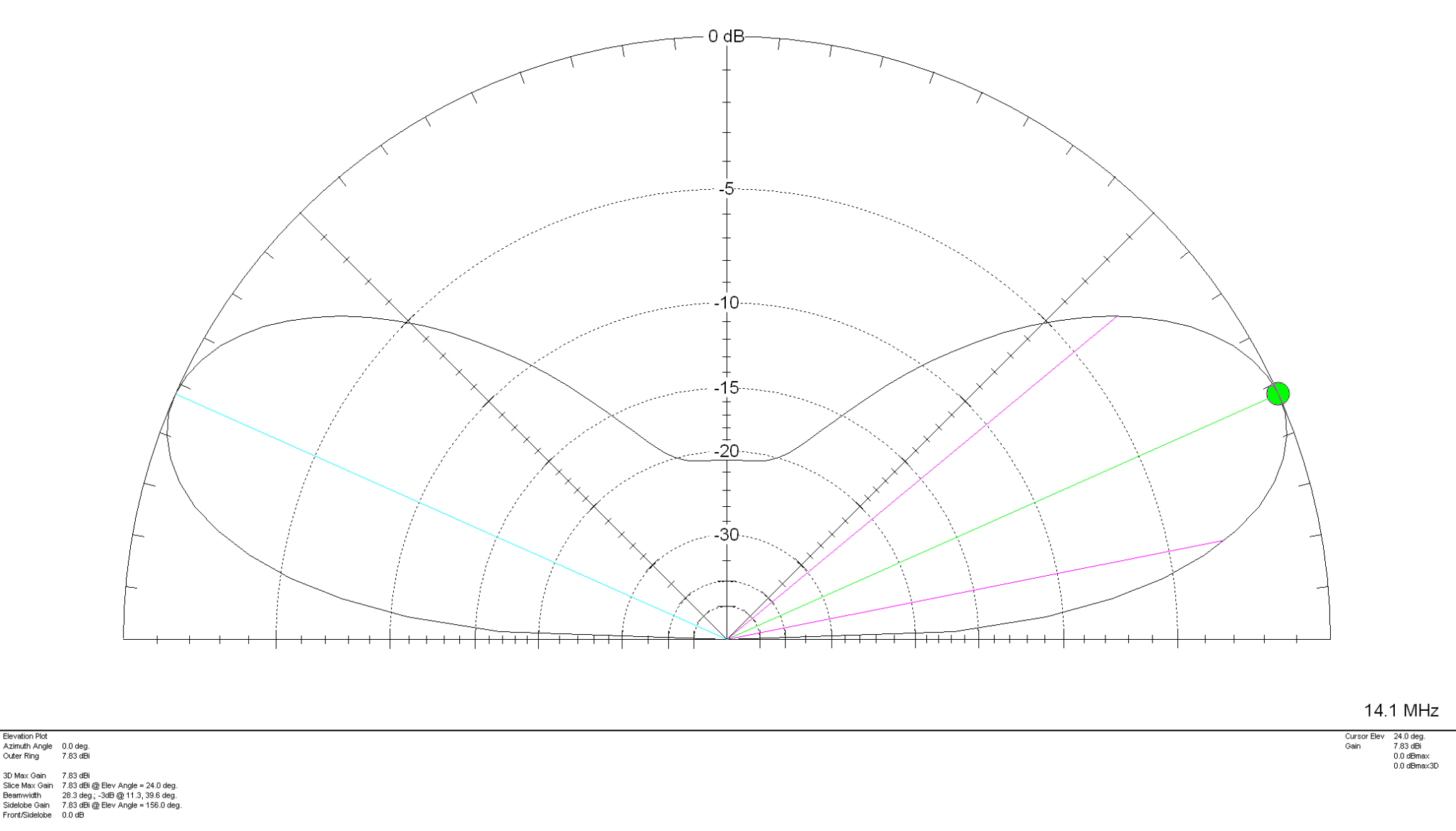
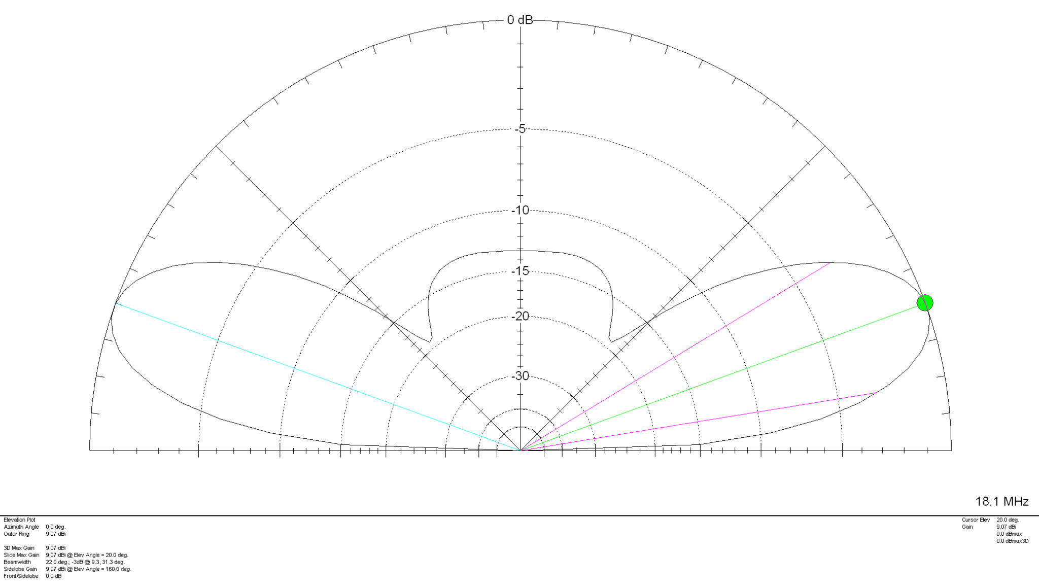
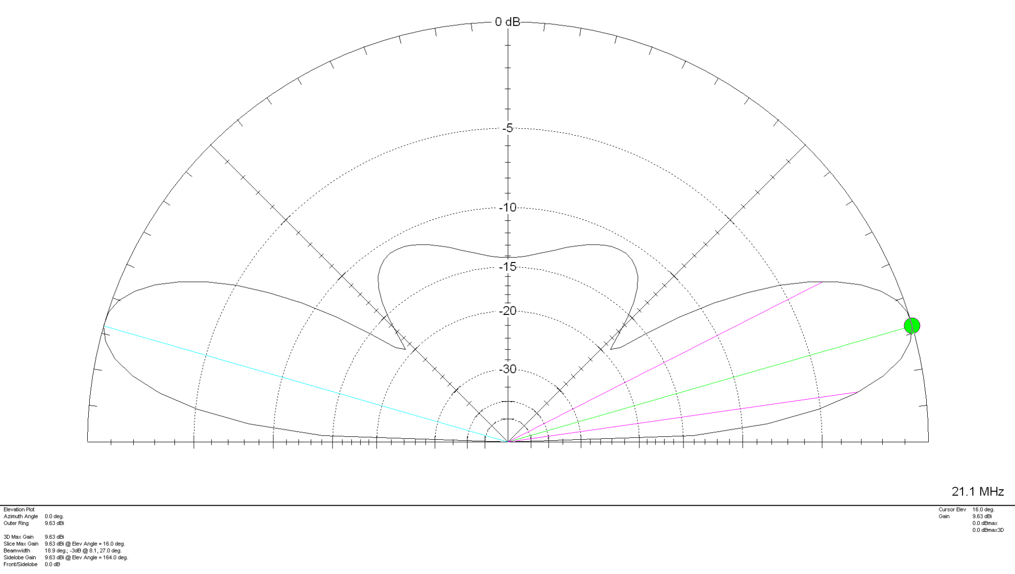
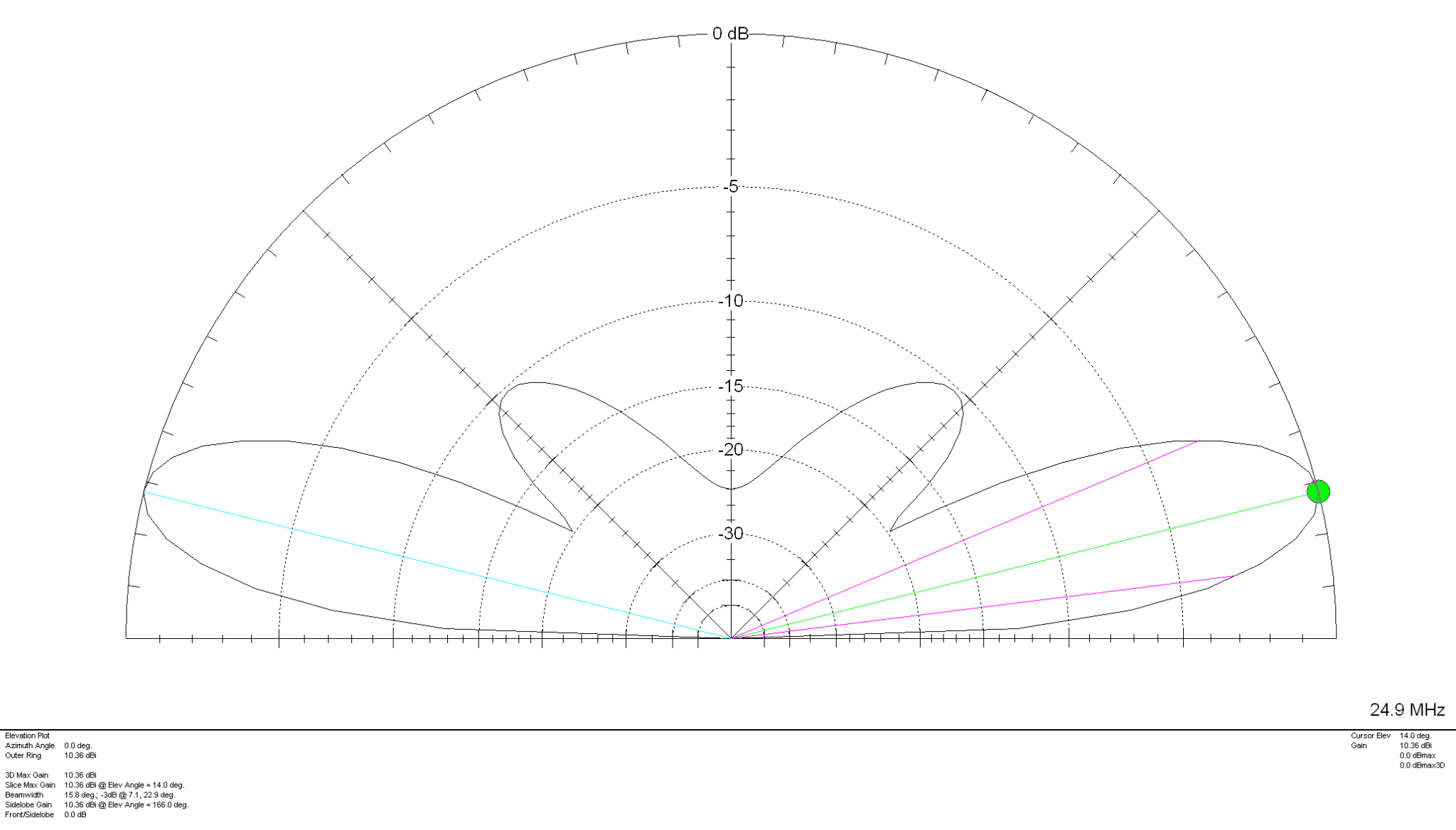
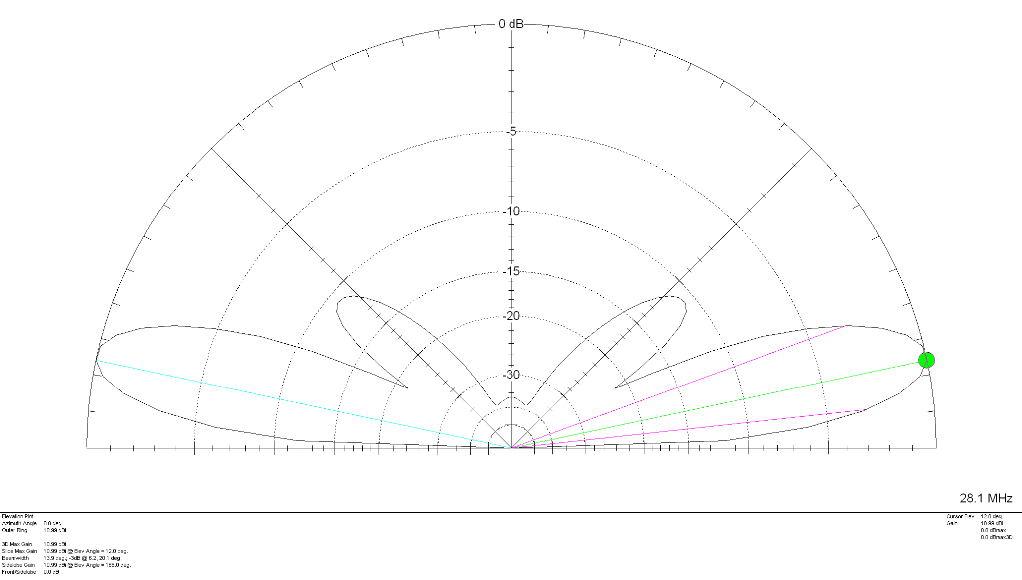
Looking at the 2D Far Field Plots this antenna provides excellent gain at relatively low radiation angles on all bands 20m – 10m making it an ideal antenna for chasing DX.
20m Band 2D Far Field Plot 17m Band 2D Far Field Plot 15m Band 2D Far Field Plot 12m Band 2D Far Field Plot 10m Band 2D Far Field Plot
The gain on each band is as follows:
20m Band – 7.83dBi at 24 Degrees 17m Band – 9.07dBi at 20 Degrees 15m Band – 9.63dBi at 16 Degrees 12m Band – 10.36dBi at 14 Degrees 10m Band – 10.99dBi at 12 Degrees
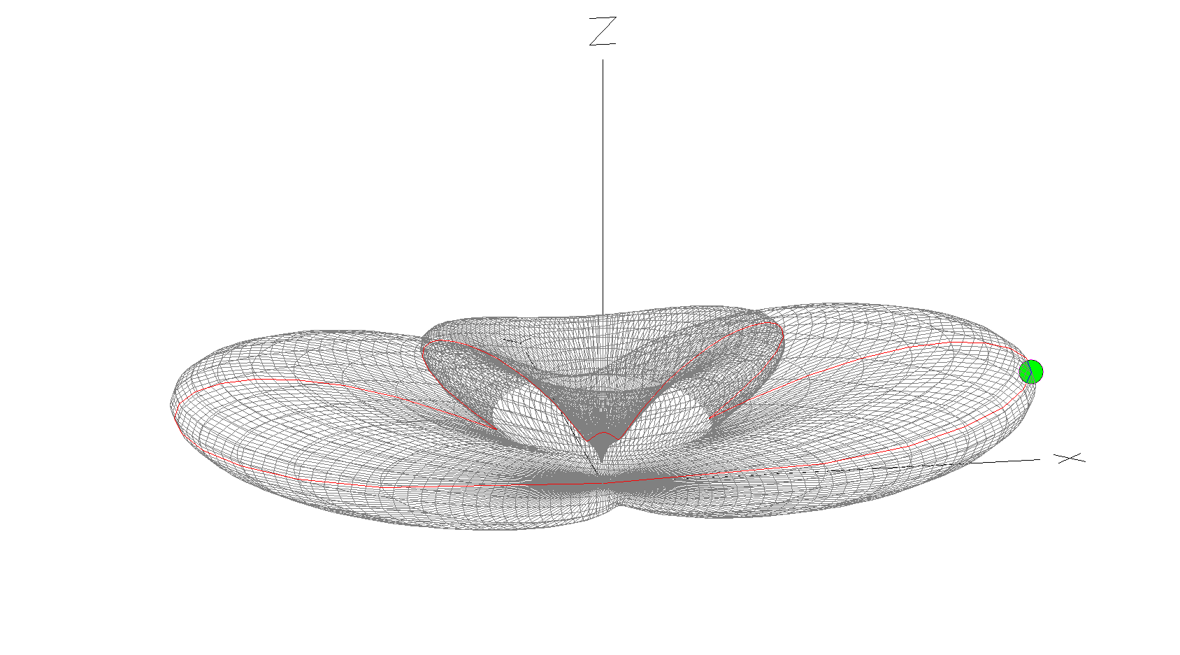
10m Band 3D Far Field Plot
The 10m Band 3D Far Field Plot above shows the typical radiation pattern for the antenna. Maximum radiation is through the loop with very little high angle radiation making it ideal for chasing DX stations. Gain increases as frequency increases however, angle of maximum radiation decreases as frequency increases improving DX capability of the antenna on the higher bands. It’s worth ensuring that the antenna is rotatable as this will then enable you to point the antenna at the DX station to maximise signal strength at the DX end. Pointing this antenna North/South makes it great for working VK/ZL over the North Pole whilst at the same time being able to work South Africa from the UK.
Summary:
Horizontal Wire Lengths: 3m @ 20mm Diameter Vertical Wire Lengths: 9.2m @ 2.5mm Diameter Modelled Height above ground at Centre (Conductor 2): 10.6m Feed Type: 4:1 Balun + ATU / Remote Auto ATU / 450 Ohm Ladder line with 4:1 Balun & ATU
Whilst I’ve been waiting for the weather to improve so that I can get my QO-100 dish antenna up I’ve been working on my QO-100 Node Red dashboard.
The idea of the dash board is to bring together the operating of the receiver and transmitter into one control centre so that the two separate devices are able to communicate and behave as if they were actually one device, like a transceiver rather than being individual components.
Ideally I would like to have the transmitter and receiver talking to each other such that when the VFO on the transmitter is incremented/decremented the receiver VFO also moves by the same amount.
By doing this the receiver VFO should always be in the right place on the 10Ghz band to hear my 2.4Ghz uplink signal and of course, any station coming back to my CQ calls.
So far I’ve only been working on the receive part of the Node Red flow, it’s certainly been a lot of fun getting it put together.
I control my Funcube Dongle Pro+ (FCD) using GQRX SDR on my Kubuntu PC. This software is working extremely well with the FCD and I’m happy with the level of functionality it offers.
GQRX SDR has the ability built in to control the SDR via remote TCP connection using RIGCTL protocol. Currently there isn’t a RIGCTL node available for Node Red so I have written a number of Javascript function nodes that provide the appropriate functionality in conjunction with a standard Node Red TCP node. This is working extremely well on the local LAN in the radio room and is proving to be very stable and responsive.
M0AWS QO-100 Node Red Flow – Receive Section
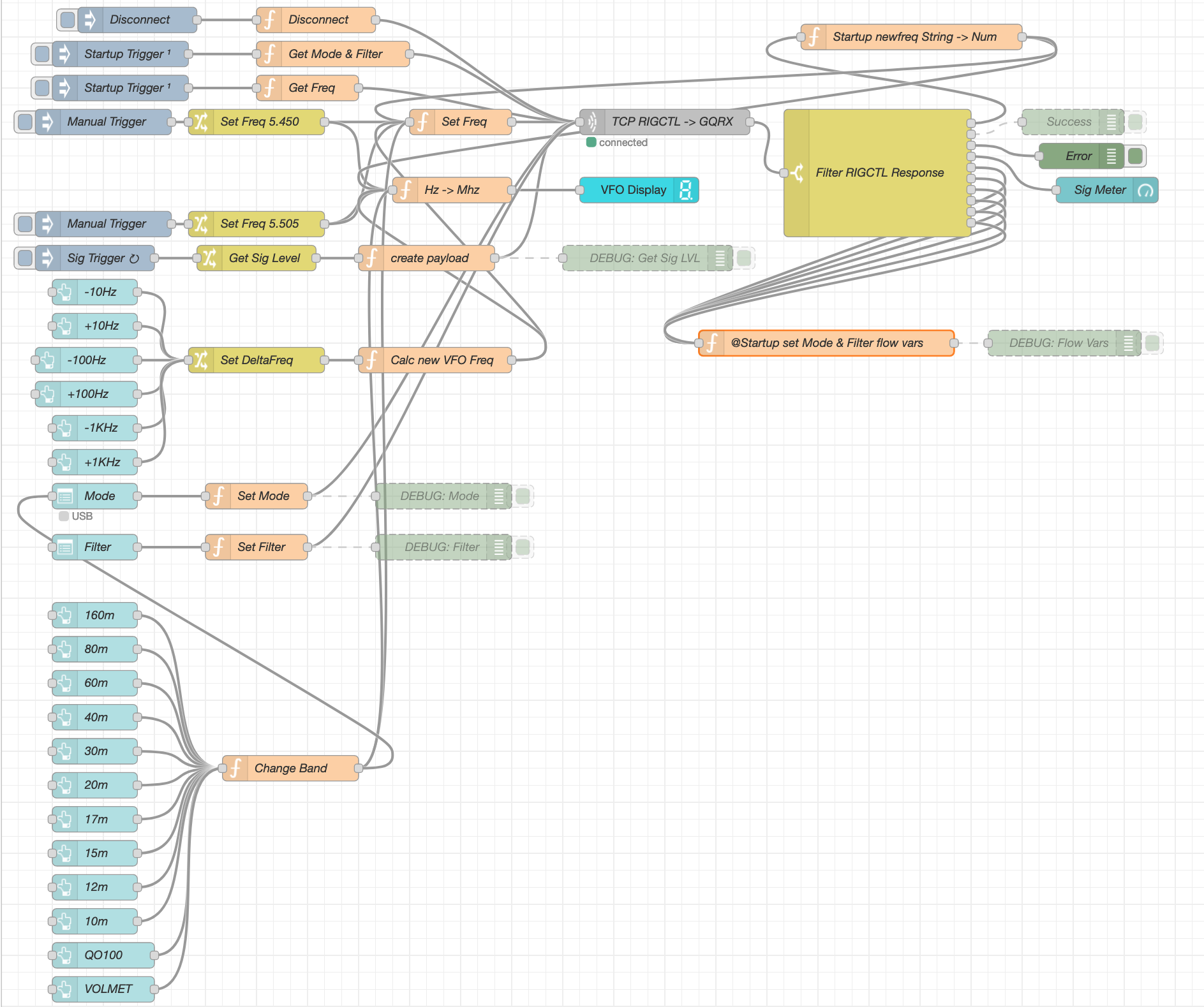
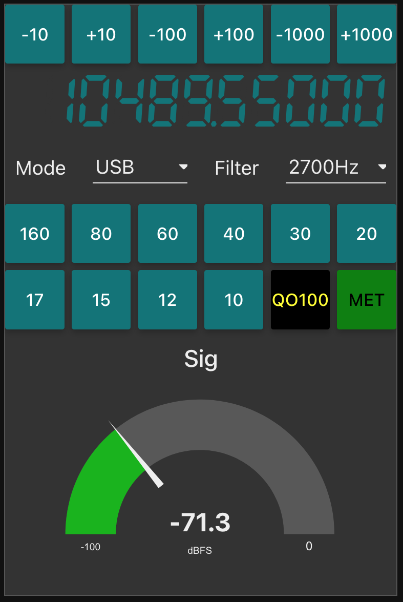
The flow for the receive section of the dashboard looks fairly complicated but, in reality it’s really not too difficult to get to grips with. The receive flow provides the facility to switch bands, switch modes, change receiver filter band width, display a realtime signal strength meter, receive +/- clarifier in 10/100/1000Hz increments and put the receiver into QO-100 mode where the SDR VFO is tuned to 739.550Mhz whilst the dashboard VFO shows the QO-100 downlink frequency in the 10Ghz band. This is all working very well and I’m happy with the initial result.
M0AWS QO-100 Receive Dashboard in QO-100 mode
I now need to start work on the transmit side of the QO-100 dashboard and get communications between my IC-705 transceiver and the FCD SDR working via Node Red. This could be a little more challenging as it will involve communicating with the IC-705 via WFView over wifi.
After much reading and viewing of youtube videos I have finally settled on the parts that I want to use to build my QO-100 Satellite ground station.
Initially I’m only going to build the receive path of the QO-100 station. From the articles and blogs I’ve read online all the experienced Amateur Radio satellite Op’s recommend getting the receive side sorted first and then moving onto the transmit path.
I need to stress here that I have no experience of radio above 433Mhz (70cm), a band that I have only used a handful of times. 99% of my Amateur Radio life has been spent below 30Mhz and so this is going to be a very new experience for me.
So, what am I going to purchase for the receive path?
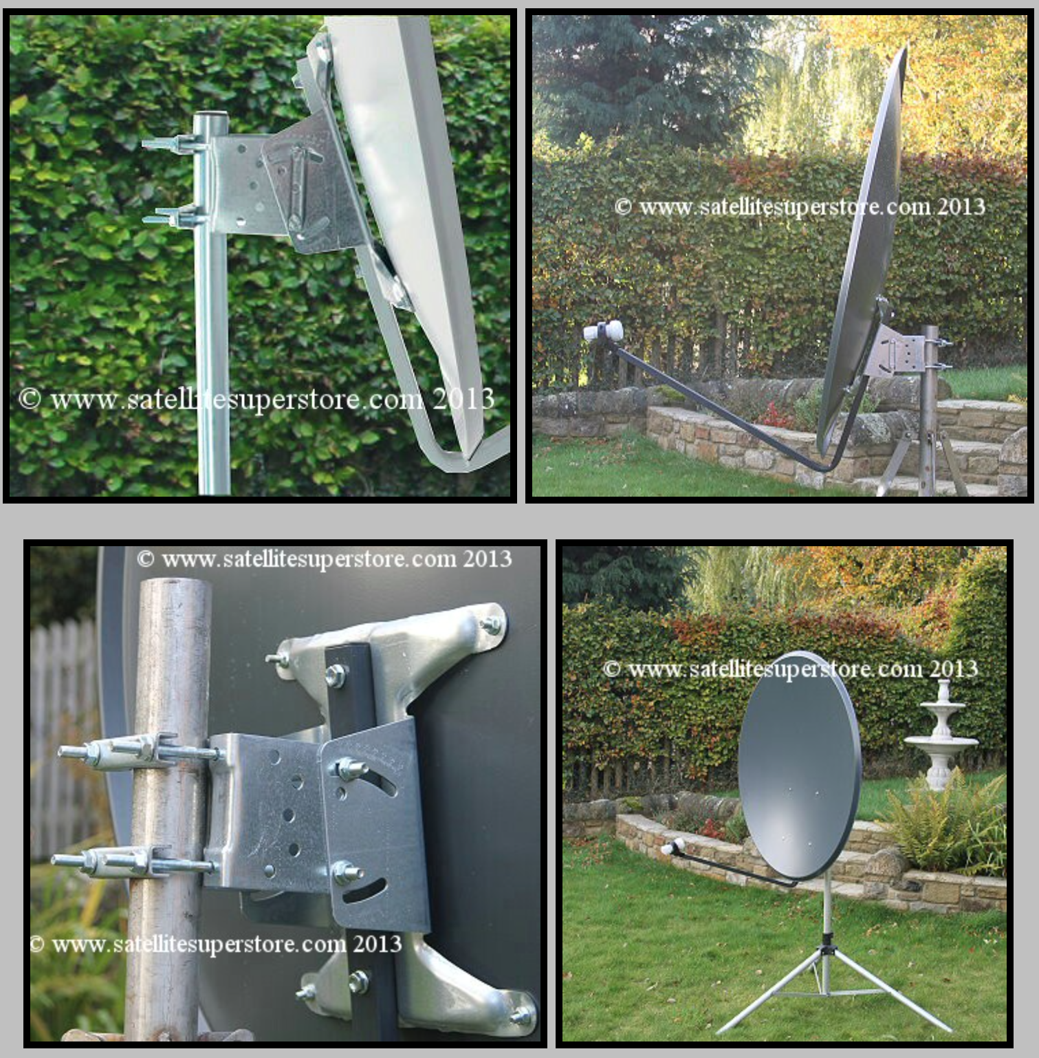
I’ve settled on a 1.1m off-set dish from the Satellite Super Store that should give me plenty of gain if I manage to get it pointed successfully at the bird.
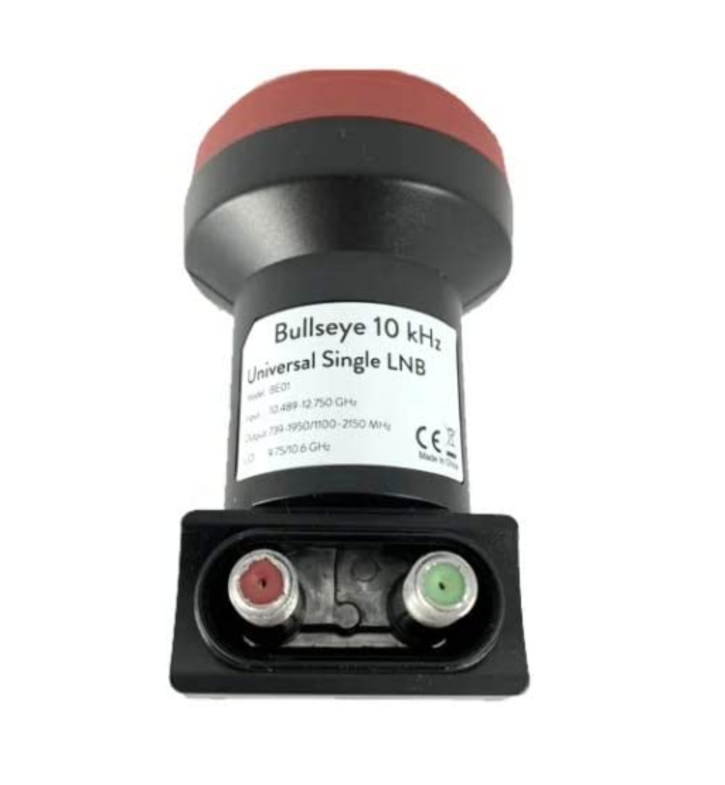
I’ll pair a Bullseye 10Ghz TCXO LNB with the dish to give me a high stability receive path that shouldn’t wander too much up and down the band with temperature changes throughout the seasons.
1.1m Off-Set Dish for QO-100
The Bullseye LNB gets extremely good reviews from the HAM Satellite community, although it is a little on the expensive side compared to many others available. Since I only want to do this once I’ve gone with the more expensive option in the hope that it gives me the stability I’m looking for.
Since we’ve never had satellite TV here at home I’ve only just learnt that LNBs require a voltage feed since reading about other peoples QO-100 station builds. Most LNBs can be used for either horizontal or vertical polarisation and are switched by feeding with either 12v or 18v respectively. The LNBs also use this same voltage feed to do the frequency down conversation and some amplification of the received signal.
At the moment I’m only looking to get onto the narrowband part of the QO-100 satellite service and so I will need to feed the LNB with around 12v to ensure vertical polarisation is achieved. The easiest way to do this is to inject the 12v feed up the coax cable to the LNB.
Bullseye 10Ghz TCXO LNB
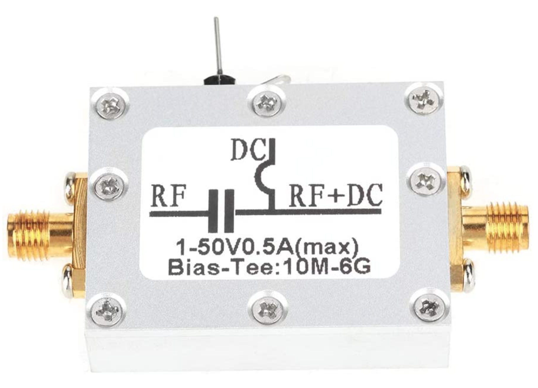
To achieve this I will need to purchase a little circuit called aBias Tee. This relatively simple circuit consists of a capacitor and inductor combination that stops the 12v from going back into the receiver whilst at the same time stopping the RF from going back into the power supply.
Bias Tee units are relatively cheap to buy online and I have decided to get one from Amazon that has been recommended in a number of blogs posts I have read during my research.
Broco Bias Tee
With these parts ordered I now need to source the materials to mount the dish up above head height in the garden with a clear view of the sky in the direction of the satellite.
Getting the dish up high enough to be above head height will be important for when I get the 2.4Ghz uplink path in place. At these frequencies it’s important to ensure that no one is able to walk across the front of the dish whilst I’m transmitting. I’m hoping to get the dish up about 3m in the air in such a fashion that it is rigid enough to stop the dish moving around in the wind. I must admit I’ve not done any wind load calculations for the 1.1m dish so I’ll have to see how it goes over time. Fortunately where I want to put the dish is fairly well sheltered from the north wind that often howls through here so, hopefully it won’t be an issue.
The 2023 new year has got off to a great start here at the M0AWS radio shack with my first QSO with New Zealand since setting up the new radio room.
It’s been almost a year now since I started putting the radio room together and throughout all this time I’d not been able to secure a complete QSO with New Zealand.
Well today was the day that I finally achieved what seemed like the impossible.
M0AWS WSJT-X QSO Map as of 3rd January 2023
ZL4AS was the first New Zealand station that I’d managed to complete a full QSO with, up until now I’d made a few ZL contacts but, never managed to complete the QSO due to conditions on various bands.
The band of choice today was 17m, a great WARC band that has provided me with much of the DX over the last year. This band really does give full global comms when it’s open.
With a new longest distance of 11776 Miles to ZL4AS in Balclutha New Zealand, I’m looking forward to see what new countries 2023 brings to the M0AWs radio room.
Having just completed building my new radio shack I thought what better way to break it in than to do an all night radio session chasing the DX.
All nighters aren’t anything new for me, I did many an all night session low band DXing when we lived in France (F5VKM). Back then I had a massive cellar, part of which was a very well fitted out radio shack. With some very large antennas in our field out back I was truly spoilt with some great times on the 160m band in the dark winter months.
Now back in the UK and only just getting back into the hobby after a long break things are somewhat different. I now only have a typical small UK garden and only vertical antennas. Better than no antennas though!
The new radio shack is small compared to my super spacious setup in France but, it’s perfectly formed with all facilities.
For my over night radio session I decided to use my trusty Yaesu FTDX10, it has the best receiver I’ve ever used and is built to withstand the long haul operation.
Antenna wise I decided to use my 30m band EFHW vertical that can be tuned on most bands from 80m and upwards. I use a CG3000 remote auto tuner to match this antenna to the 50 ohm coax feed and it does a great job.
Being comfortably setup in the shack I tuned up on the 30m band and had a listen to see what shape the band was in.
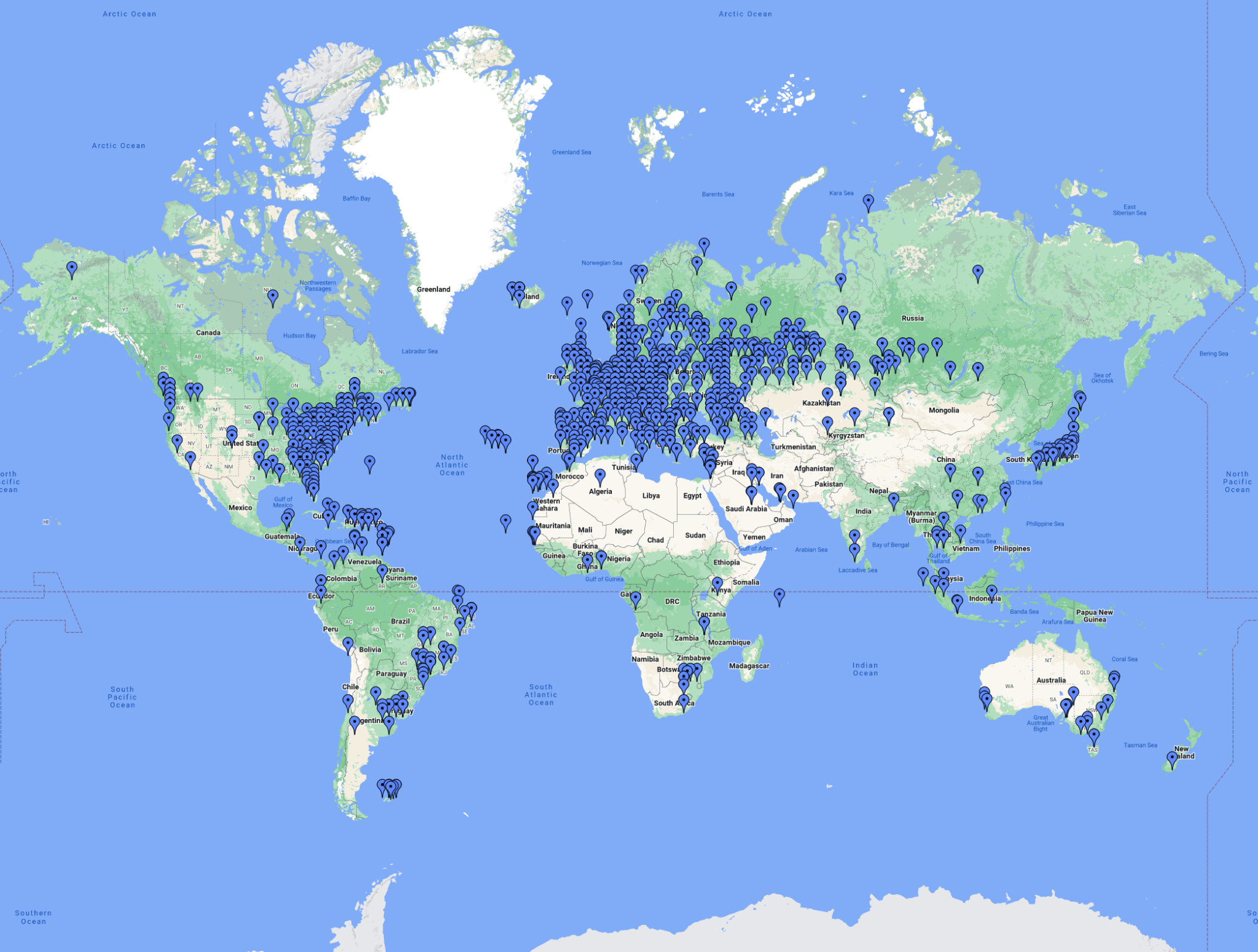
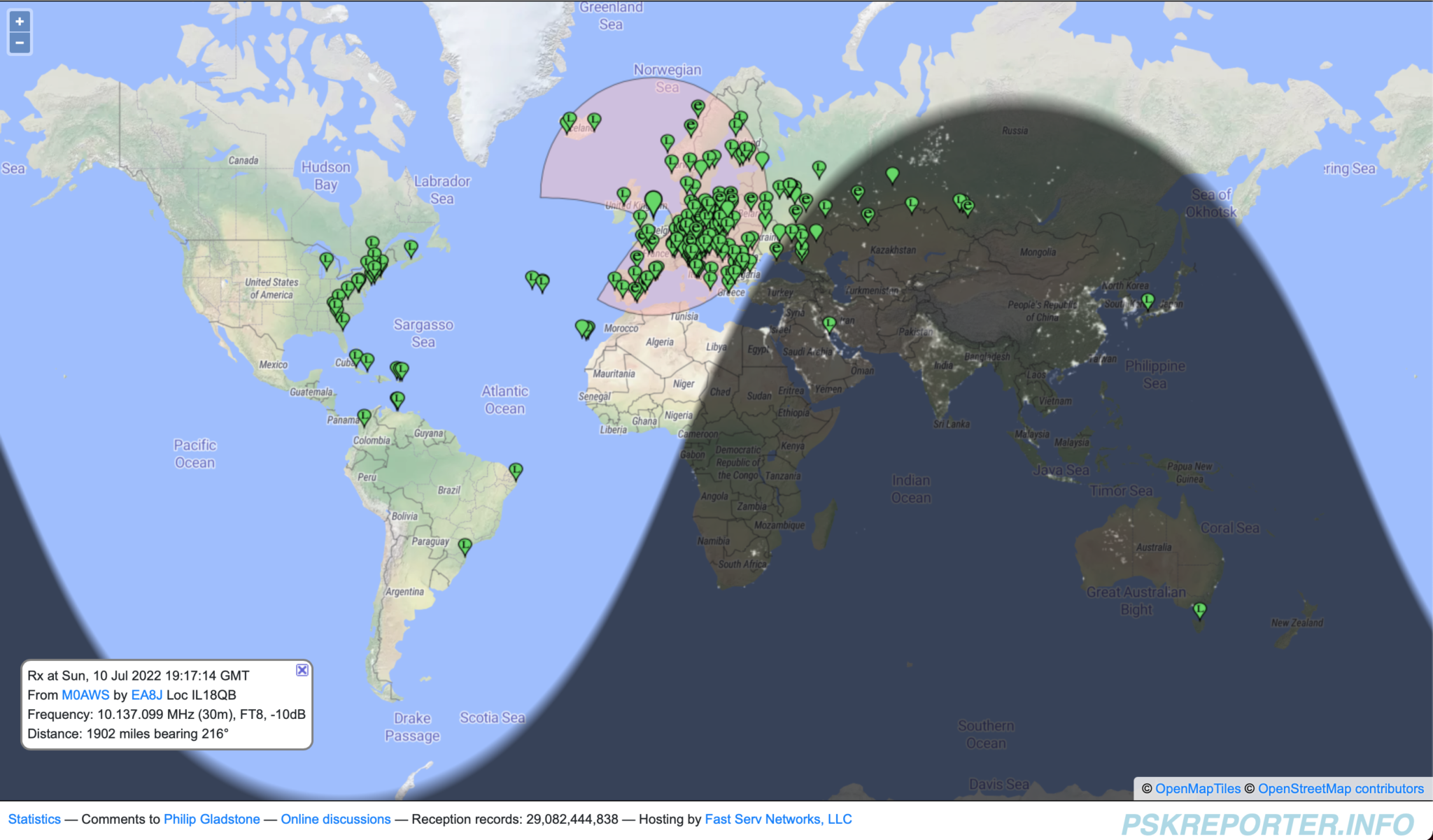
Stations heard on 30m 10/11-07-22
Using FT8 I worked a bunch of European, Russian/Asiatic Russian stations with ease, the band was in fairly good shape albeit localised around Europe and Russia. Wanting to work stations a little further afield I decided to move up on to the higher bands. 12m is a band I really like but, always seem to miss when it’s open.
Tuning up on the 12m band using the same vertical that I was just using on the 30m band the FT8 section was packed with signals. At last, I’ve tuned up on the band when it’s open!
I suddenly noticed Bobby, VP8ADR down in the Falkland Islands in the WSJTX waterfall and gave him a call. He had a fair few people calling him and so I joined the list. In no time at all Bobby answered my call and we exchange SNR reports of -8dB both ways. This was surprising as later on one of the FT8 Facebook groups Bobby stated he was using 200w into a Hexbeam during our QSO, I was only using a measly 18w into my Vertical, I would had expected a much lower SNR report. Clearly Bobby’s setup was doing all the work!
Right after the QSO with Bobby I immediately went on to work PY7ZC, LU8YD, PY2ATI, LW6EQC, PY2EBD and PY2THO all in quick succession. With the Falklands, Brazil and Argentina in the log so soon it was looking like it was going to be a fun packed night.
Next up on the waterfall was 9Y4DG in Trinidad and Tobago and 8P6ET in Barbados, two really nice locations to get into the log and new ones on 12m for me.
Having worked all the DX I could hear on 12m and not wanting to just spend hours working endless European stations I tuned down onto the 17m band using the same vertical antenna. This antenna really does work well on bands it’s not designed for.
First 3 stations in the log on 17m were all from Japan, JR3NZC, JQ6RUP and JA5BDZ. With all 3 stations being well on the way to 6000 miles away this was a good start. The propagation strangely swung to the west and I got YV5DRN from Venezuela in the log.
Not seeing any other stations that I wanted to work I retuned back onto 30m again and found it was open to South America and the Caribbean.
In no time at all I had YV4CLF in Venezuela, HK2AQ in Colombia, NP4TX and NP3XF in Puerto Rico and PY7ZC in Brazil all in the log.
Being in complete darkness I decided to tune down on to the 60m band, one of my favourites, to see if there was much going on. Sure enough there were a few stations active on the limited space available.
First station worked was a new one for me FP/KV1J on St. Pierre and Miquelon Island just off the coast of New Foundland. I have to admit I had no idea where this little island was and confess to having to look it up on google maps.
I then went on to work a few East Coast USA stations all with good SNR reports for this time of year.
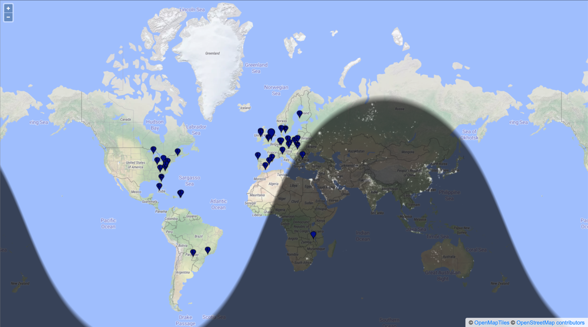
Stations heard on the 60m band 11-07-22
Having worked all the notable DX on 60m I tuned back onto the 17m which was now wide open to the world.
I stayed on this band for the rest of the night well into the morning grey line and beyond working some great DX including some new ones for me.
I worked many East Coast USA stations but, stations of note were 6Y5HN in Jamaica and AK6R, K6EU and K6EI in California on the West Coast USA. It’s rare for me to get into the West Coast USA for some reason.
UA0SDX in Irkutsk Siberia was also a nice one to get in the log. This is a town I was going to be riding my motorcycle through on my Mongolian trip before COVID19 and the war in Ukraine broke out and stopped the trip from happening.
It was good to get an Ozzy call in the log too, VK6EI on the West Coast of Australia came in at a strong -15dB SNR giving me a surprising -14dB SNR report, incredible considering I was using just 22w into my vertical antenna.
Well after sunrise the DX was still pouring in and I worked KL7TC in Fairbanks Alaska, a new one for me that made me very happy as I’d been trying to get into Alaska for some time but, never seemed to time it right. Today was my day!
Another station I was really pleased to get into the log was V31MA. I’ve tried to get a QSO with this station many times but, have never succeeded until today. I called for about 20mins and eventually got a reply putting a huge smile on my face. -16dB SNR sent and -19dB SNR received, I was happy that I finally have Belize in the log.
The last station worked was RA0FF way over on the far East Coast of Russia, the complete opposite direction to Belize. Located in Yu-Sakhalinsk right on the Russian coast opposite Japan and at 5270 miles, this is my longest distance Russian station worked so far and one I was very happy to have in the log. I always get good take off towards Russia whether it be directly east or over the North Pole to the far eastern parts of the Siberian wilderness.
I had a great night chasing the DX on the HF bands and being retired didn’t have to worry about going to work after such a long night. I highly recommend that you try an all nighter at least once in your HAM radio career, you get the opportunity to work stations that you’d normally not hear during the day time hours.
You can see the full list of stations worked on the over nighter on my WSJTX Log page.
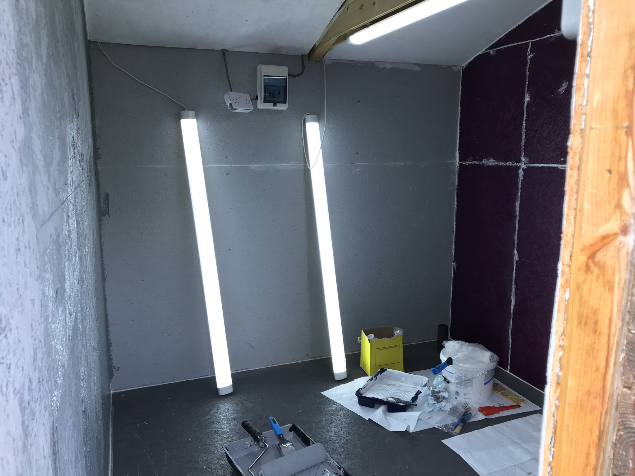
Over the last couple of weeks my wife and I have been busy converting part of my old motorcycle workshop into my new radio shack.
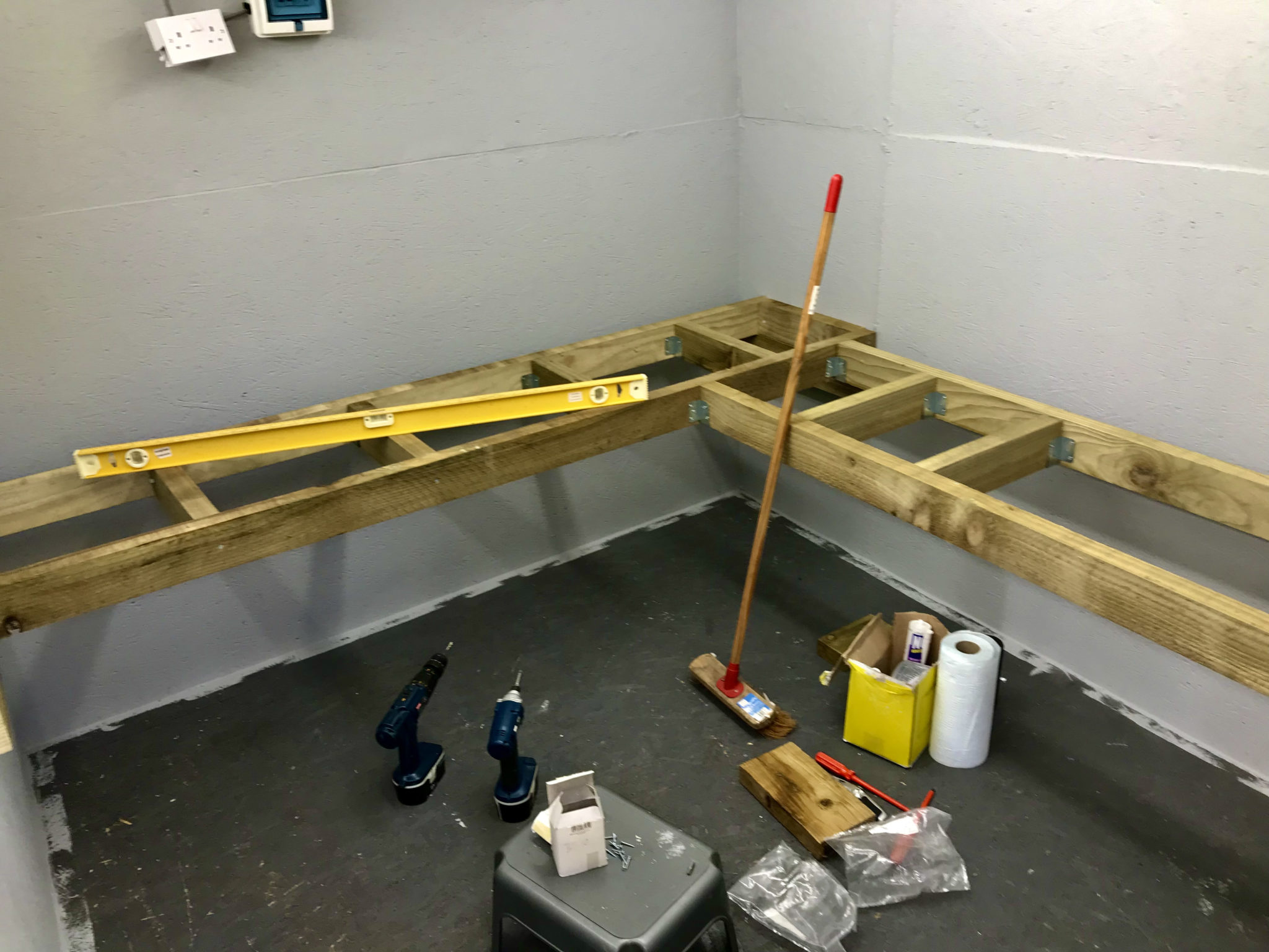
To save money we’ve custom built the desk ourselves using timber from a local supplier. I’ve done all the 240v power and lighting installation with a dedicated feed from the main distribution panel in the house.
Converting my old motorcycle workshop into my new radio shack
Custom building the desk gives us a huge advantage in that it allows us to maximise usage of the available space. Using 10mm sterling board covered with 10mm plywood makes the desk solid enough to sit on whilst fitting all the power sockets.
Bennie overseeing the project
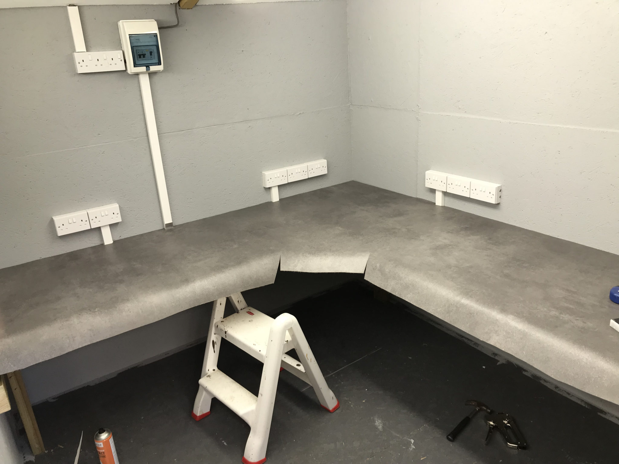
We used a good quality padded vinyl flooring for the desk covering as it allowed us to cover the desk area in one continuous piece. It was challenging to get all the cuts in the right place and get it glued down without it moving but, with a little care and patience we got it done. We’re both really pleased with the results!
Covering the desk with good quality vinyl flooring
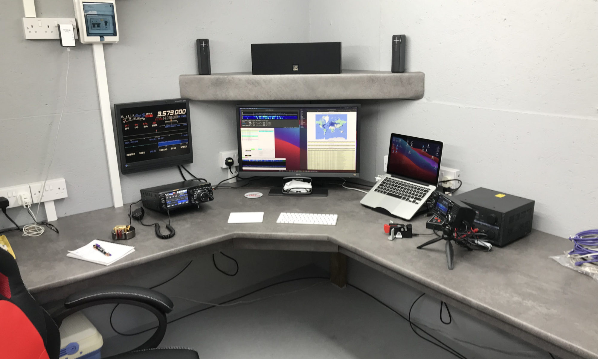
I’ve just got to install some cable management and shelving to complete the project but, overall I’m really pleased with the new radio shack. I’m looking forward to the winter low band DXing season!
The new M0AWS Radio Shack
More soon …
We use cookies to ensure that we give you the best experience on our website. If you continue to use this site we will assume that you are happy with it.