Building MB7IBW 2m AllStarLink Internet Gateway

I’ve recently built another AllStarLink node to compliment my personal 70cm band SHARI node as I thought since I have a full duplex dual band handheld it would be great to have another node that I could connect to FreeStar or HUBNet at the same time as monitoring the Matrix node.

Rather than build another personal node I decided this time I would build a public node, obtain a callsign from the RSGB and make it available to the HAM’s locally on the 2m band.

This would make it possible for me to monitor both nodes at the same time using my Wouxun KG-UV9K full duplex dual band handheld whilst providing the local HAM community with access to the AllStarLink network.

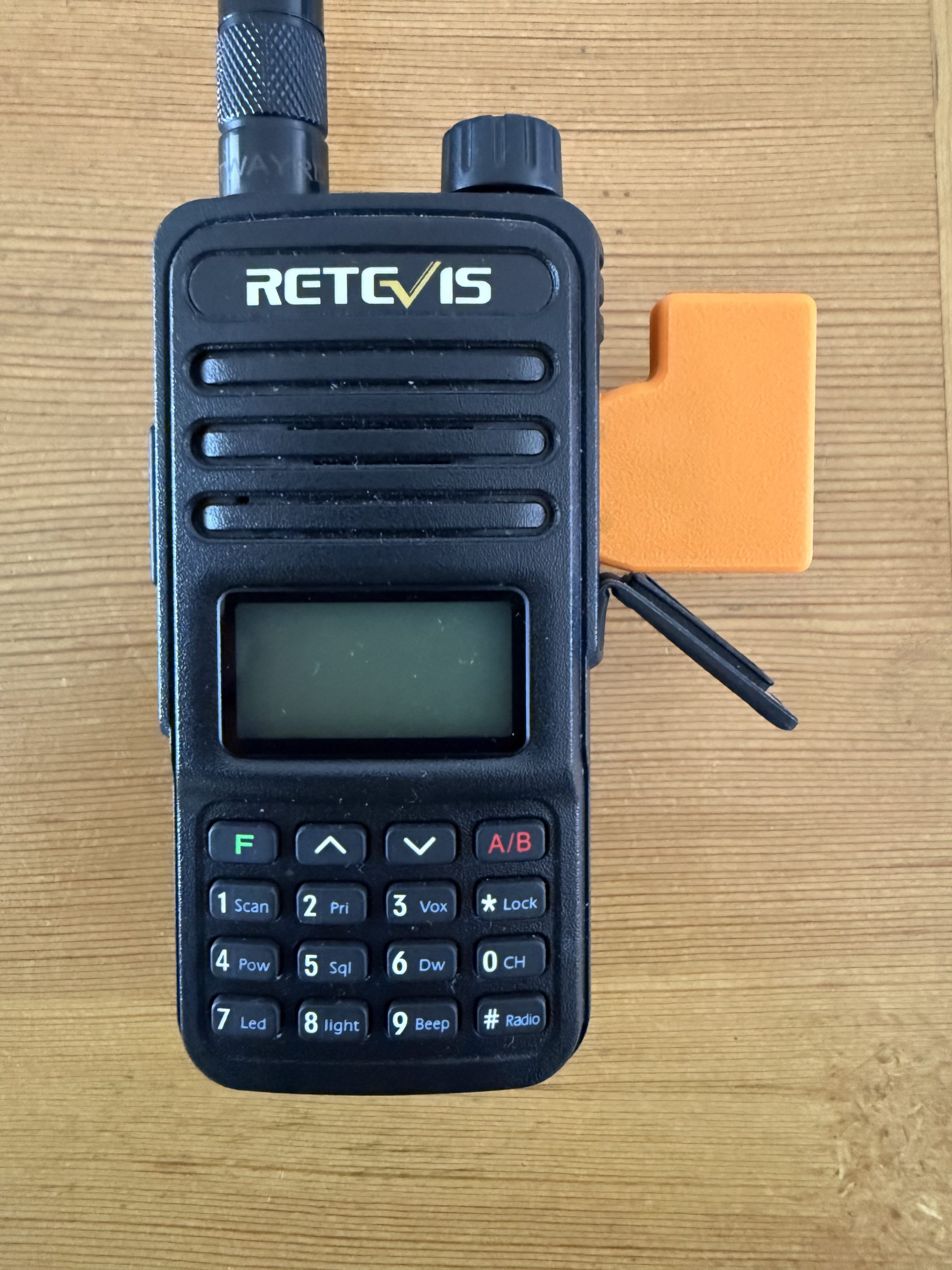
Initially I thought I may be able to use my old Retevis RT85 handheld and AIOC board for the 2m node but, after a little testing it soon became apparent that it overheats during long overs (which are common on AllStarLink) and so, I needed to find another solution.

AIOC connected to the Retevis RT85.

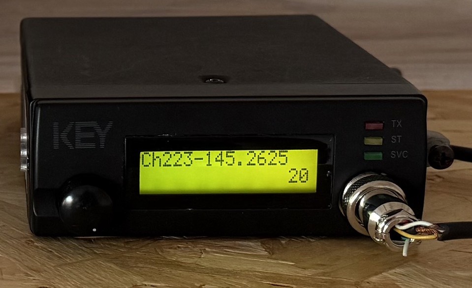
Chatting about this in the main Matrix HAM Radio room Steve, M0XVT sent me a message saying he had an old Key KM-4000 converted PMR radio that had been reprogrammed for the 2m band that he was looking to sell and that it might be ideal for the new node. Wasting no time, we came to an agreement and I was soon the proud owner of a converted PMR transceiver.

Key KM4000 2m Band PMR Radio

The KM4000 transceiver has a standard output of 15w, 10w more than I needed for the gateway and so I had to reduce the output. A quick search on the internet and I found the Thames Valley Repeater Group website that had all the information required to turn down the output.

I also had to reprogramme channel 1 to the frequency and CTCSS tone allocated to me by the RSGB so that in the event of a power outage when the radio came back on it automatically jumps to channel 1 which would be correctly setup for operation.

Unfortunately the software for programming the radio is only available for windows and so I had to build a virtual machine running windows 10 to be able to reprogramme the radio.

Once this was done I rewired the AIOC USB audio device to work with the KM4000 radio and built the AllStarLink node on a spare RaspberryPi 4.

For an antenna I made a simple end fed vertical dipole from some RG58 coax and mounted it 8m up on one of my Spiderpoles in the garden. Running a coax feed out to the antenna I did some tests into the Parrot to get the audio levels setup and checked that the DTMF codes were interpreted correctly and that the node switched connections without error.

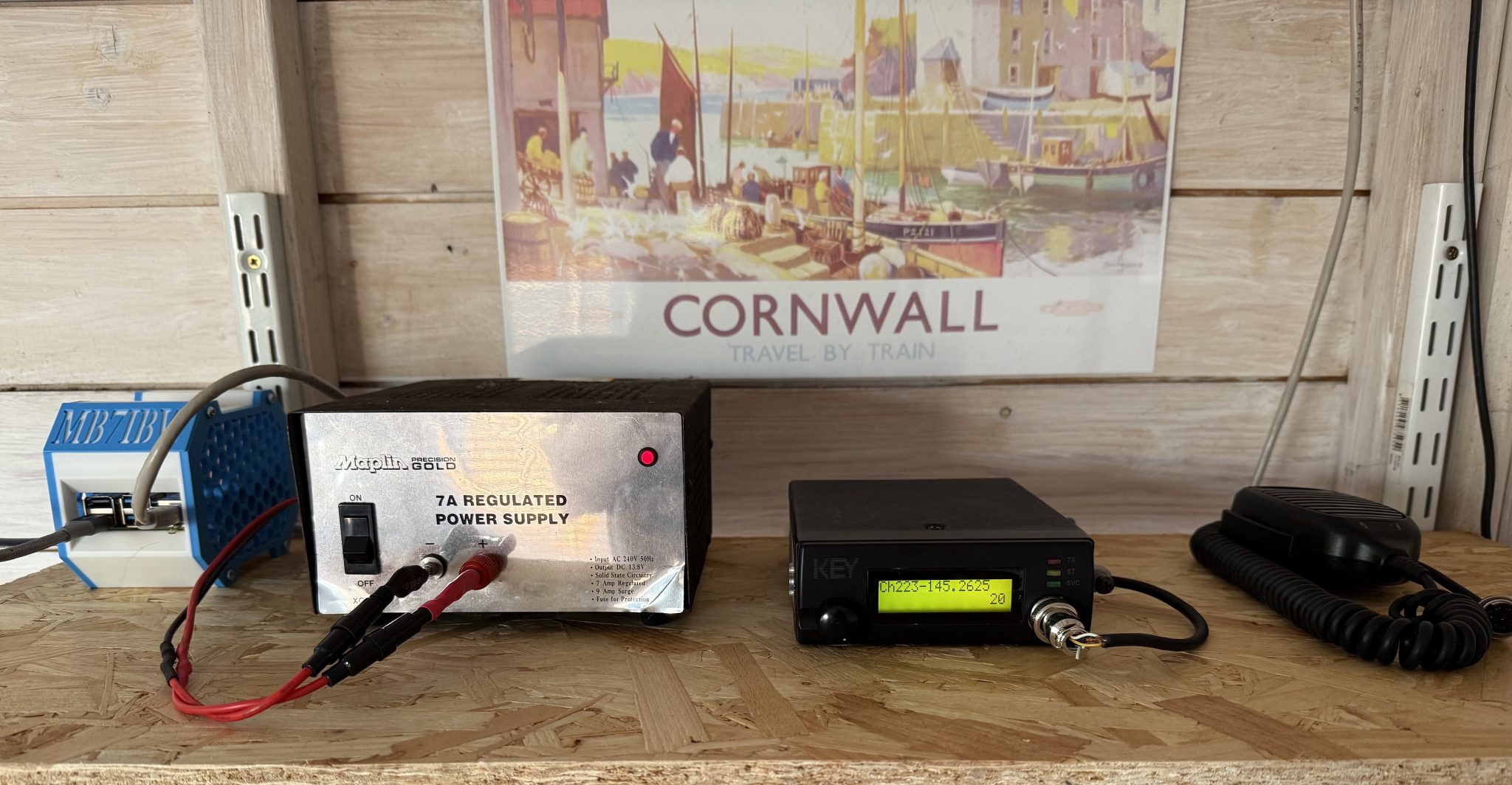
MB7IBW Internet Gateway hardware at the M0AWS QTH

Once this was done I had a few test conversations with stations on the Matrix node and FreeStar to ensure all was fine and then set the gateway status to “Operational” on the RSGB website.

This worked fine for a while with myself and some local stations using the node regularly but, then the hot weather arrived and things started to overheat. The transceiver was getting incredibly hot in the 30c+ summer temperatures and the power supply was also running extremely hot and so I decided to add some cooling.

Cooling the PSU was simple, it has a perforated top panel to which I strapped a cooling fan. This worked great and brought the temperature of the PSU down considerably.

The radio wasn’t so easy to cool. It has a solid case cover top and bottom and so cooling wasn’t going to be a simple affair.

I decided to remove the covers and drill some holes into them to allow airflow through the unit and strapped a fan to the top cover to pull the hot air out. This worked well however, on both transmit and receive I now had a warbling sound on the audio that was caused by the motor of the fan when powered up.

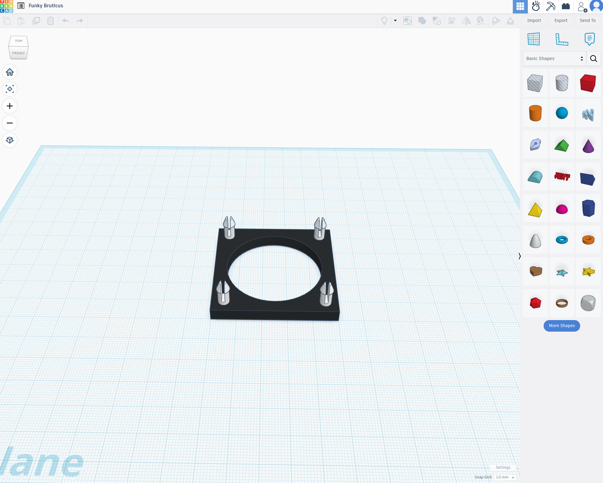
I found that lifting the fan up away from the case of the radio the warbling audio disappeared and things were back to normal and so, I decided to design a cooling tube to fit to the top of the radio to allow full airflow from the fan but, with the fan raised up away from the radio to resolve the audio problem.

Jumping into my CAD software I quickly designed a cooling tower to fit on the top of the radio that would allow the fan to sit far enough away from the radio so as to not affect the audio whilst at the same time pulling the hot air out of the radio and drawing cooler air in through the bottom of the case.

I sent the design through to my Bambu Lab A1 Combo 3D printer and set the print job running.

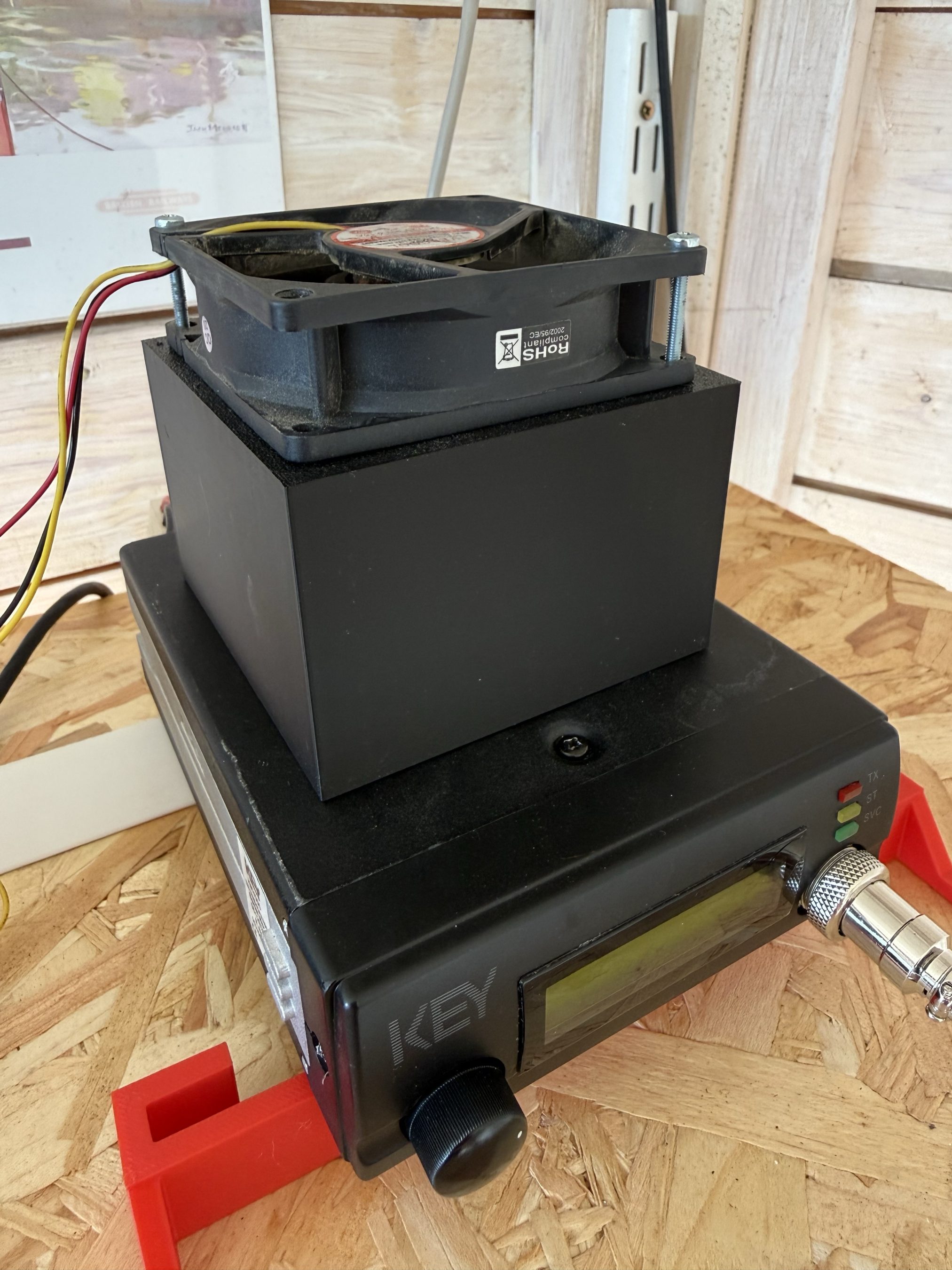
Key KM4000 Cooler
Key KM4000 Cooler

The cooler worked great with the radio staying cool to the touch and no longer overheating and reducing O/P power.

It’s amazing how much dust and dirt is in the air from all the farming activities going on at the end of our garden and how much of it is sucked in by the cooling fan. Regular cleaning is a must!

The MB7IBW Internet Gateway has been on air since mid June 2026 and has worked well. It spends most of its time connected to either FreeStar or HUBNet with connections to the Matrix Node when we have our nets.

Details on Frequency, CTCSS etc can be found under the MB7IBW menu above.

Sadly the initial interest from local HAMs has now wained and I am mostly the only user of the gateway. I was hoping more people would use it and bring some life to the 2m band, I guess time will tell.

It’s been a fun project and was interesting to go through the callsign allocation process with the RSGB representative. It was much easier than I thought it would be.

I now have all the parts to build another Internet Gateway for the 4m band. Hopefully that may attract some more interest. It’s certainly worth a try!

More soon …

Node-Red Dashboard for AllStarLink 3 Nodes

I’ve spent some time this afternoon modifying my Node-Red Dashboard for controlling AllStarLink nodes to work with the new AllStarLink version 3.

My original AllStarLink Control Dashboard was designed to work with AllStarLink 2 which I have running on an old RaspberryPi 3b on the 70cm band. The dashboard has worked reliably ever since deployment and is in use daily.

With the release of AllStarLink 3 and all the changes that it entails I’ve had to make a few changes to the dashboard flows in order to make it compatible with AllStarLink 3 nodes.

This entails not only flow changes but also the addition of two new bash scripts that are called by Asterisk to log connect and disconnect messages as they are not logged by default any more. (Seems a bit of a step backwards)

Node-Red AllStarLink Control Dashboard v3.0 for ASL3

The changes also entail disabling the temporary filesystems used by default in the new ASL3 build so that log files etc become persistent.

I’ll spend some time using the new dashboard to ensure it’s working correctly and then will release it into the wild for all those that are brave enough to move over to AllStarLink 3.

More soon …

Xiegu XPA125B Button Press

For some time now I’ve been using my Xiegu XPA125B amplifier with my Hermes Lite 2 + I/O board combo with great success. With the amp changing bands automatically it really is nice to use.

With the multitude of remote controlled smart plugs available today I’ve now got the ability to switch the station on remotely however, there’s been one issue that has plagued me until now and that’s the Xiegu amp doesn’t come on when power is applied to it, you have to press the power button on the front of the amp before it will fire up.

This of course stops me from being able to fully use the station remotely as there’s no one there to press the power button on the amp, until now.

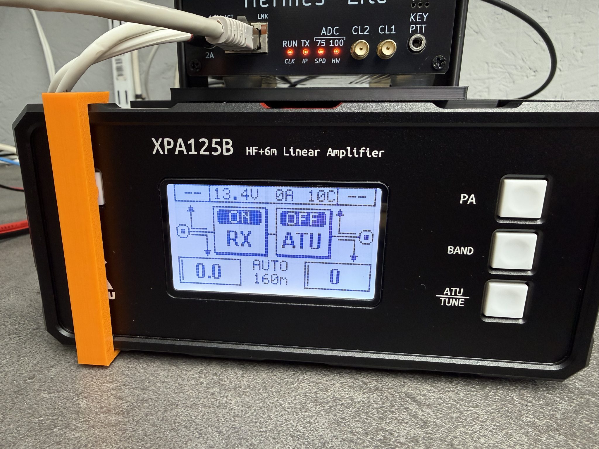
Chatting with Steve, M0XVT he discovered that if the power button is held pressed all the time the amp will come on when power is applied. This then gave me the idea of designing a button press device that I could 3D print and clip onto the front of the amp so that the button is always pressed.

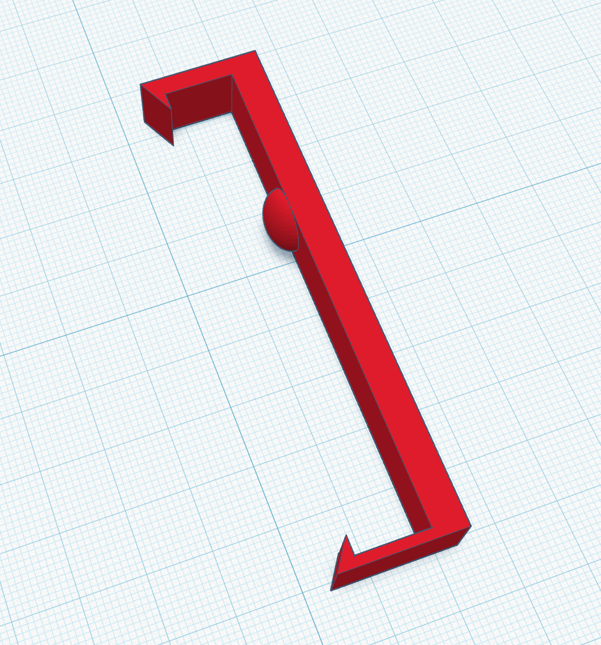
M0AWS Xiegu XPA125B Clip on Power Button Press

The Xiegu amp has a very nice flange around the front edge of the amp case that lends itself nicely to clip on a simple button press device as shown above in my 3D design software.

The button press is designed so that the top is put on first and then the bottom is just snapped into place with a gentle push. This makes it easy to get on and off without marking the amplifier.

M0AWS Xiegu XPA125B Clip on Power Button Press

In just a few minutes I had the button press design uploaded to my Bambu Lab A1 Combo 3D printer and in no time at all the button press was ready for use.

As you can see in the photo above it fits snugly to the front of the amp gently holding the power button in so that the amp comes on when power is applied. Simple but, effective.

I’m sure I’m not the first person to have this problem and so, I’ve made the .STL 3D print file available for download below.


I hope this is of use to people who want to be able to use their Xiegu amp remotely without leaving the power on all the time.

More soon …

Node-Red ADIF to Log Map Flow

Following on from my previous article on using Node-Red to build interactive log maps I’ve now reworked the flow to make it more efficient with less Javascript.

The original flow had a function that handled the issue of FT4 contacts being recorded in two different ways depending on which app you use for your FT4/8 operations.

<mode:4>MFSK <submode:3>FT4
or
<mode:8>MFSK FT4

The code I wrote to handle this wasn’t particularly elegant and so I decided to remove the code entirely and just use a simple change node.

M0AWS New node to handle FT4 more efficiently

This is the great thing about Node-Red, there’s always more than one way to do something.

With this fix in place and the old code stripped out of the format generic payload function, the new flow is much tidier and easier to comprehend.

M0AWs Updated ADI Log Map flow

With testing complete and the two maps now live on my website the flow is finally ready for release into the wild.

If you fancy presenting your ADIF logs in a more visual, interactive format then just download the flow below and import it into your Node-Red flow editor.


Don’t forget that you will need to change the path to the log files in the file read nodes to suit your setup and change the location data in the My QTH trigger to match your callsign and location. Other than this the flow should just work.

More soon …

Joining the 3D Print Revolution

For some time I’ve been considering purchasing a 3D printer so that I can create parts for my HAM Radio projects. The issue has always been, what printer to buy?

Having searched online, watched many YouTube videos and endless reading I ended up even more confused and no closer to making a decision. In the end I decided to step away from the idea for a while and see where things went.

Some time much later I ventured back to the subject and discovered the Bambu Lab 3D printer range. These were getting rave reviews and were positioned as being ideal for the total 3D printing beginner.

Once again I read as much as I could about the Bambu Lab printers, watched endless videos and searched online for supplies, spare parts etc to ensure they were readily available.

Eventually I had all the boxes ticked.

  • Relatively easy to use software
  • MacOS/Linux supported
  • Can print using the filament types I need for my projects
  • Good size print plate
  • iPhone App
  • Wireless connectivity
  • Built in camera for time-lapse videos
  • Multi-colour filament delivery system
  • Sensibly priced filament
  • Readily available replacement parts
  • Active Eco System and community

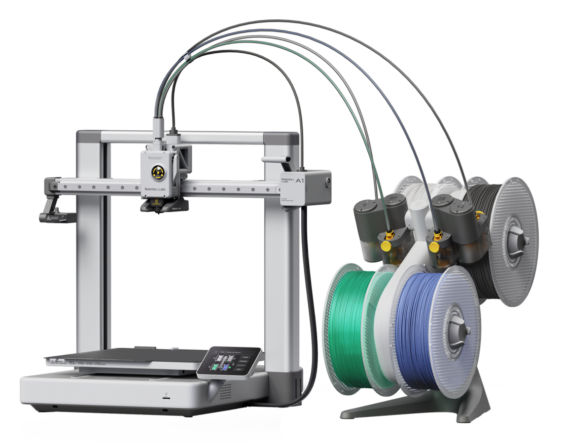
Looking at all the current 3D printers available in the Bambu Lab range I decided to purchase the A1 Combo model. This has a 256 x 256mm build plate, 4 filament feed print head and the filament Automatic Management System (AMS) that makes multi-colour printing a breeze.

With the decision made all I had to do was find a supplier. Strangely enough buying direct from Bambu Lab gave the best price and with the £10 voucher and 28% off of filament bought at the same time as the printer it was a no brainer.

£528 later I had 10 rolls of filament and an A1 Combo 3D printer winging it’s way to me.

Bambu Lab A1 Combo 3D Printer

2 days later our local DPD delivery driver arrived with 2 large boxes and a comment about how heavy one of the boxes was.

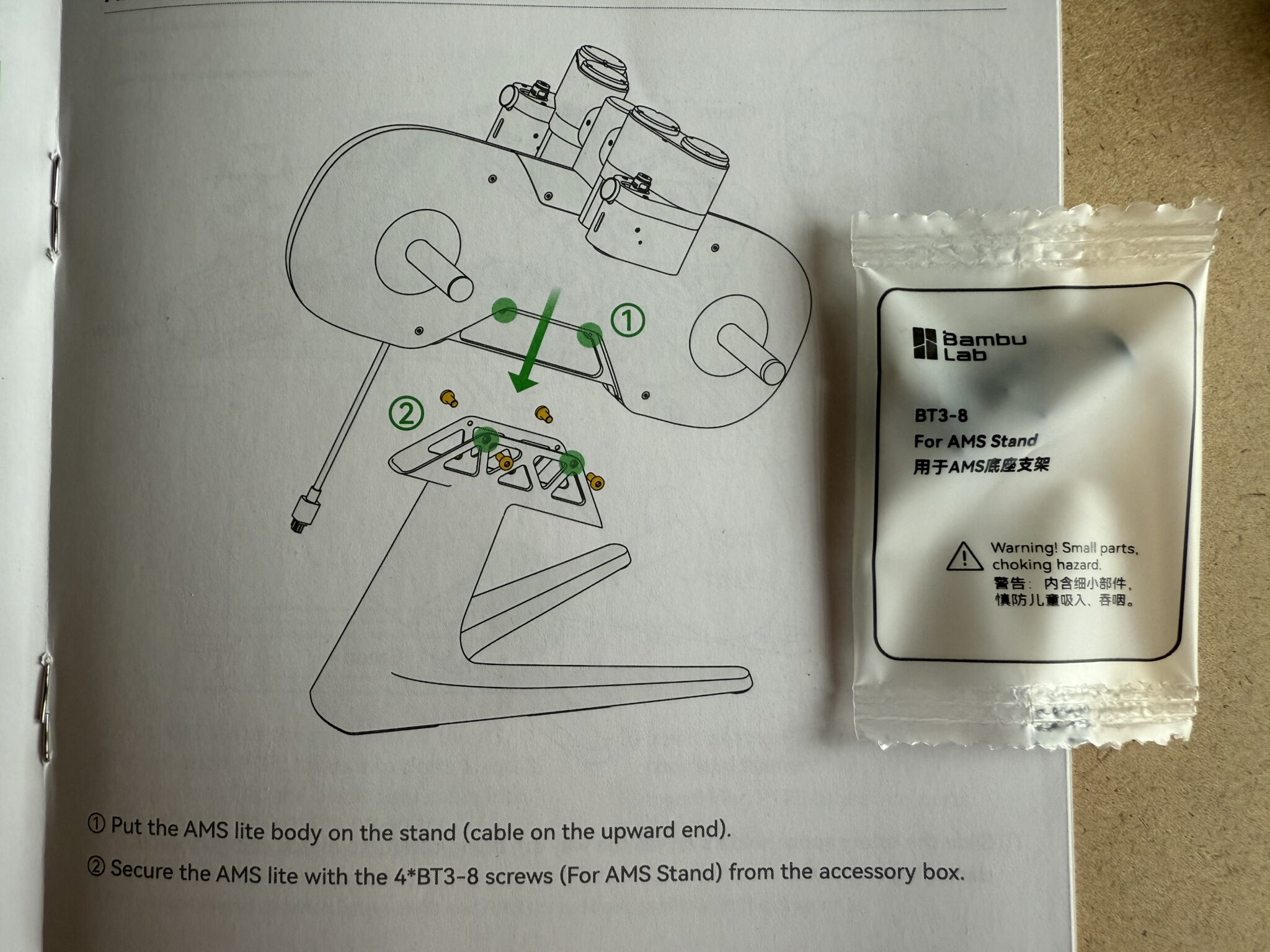
Upon opening the printer box I found it was extremely well packed. The printer comes in a partially assembled form and requires some assembly by the end user. All the parts are really well labelled right down to each packet of screws being labelled with their exact use. All the tools needed to assemble the printer are included as is the easy to follow manual.

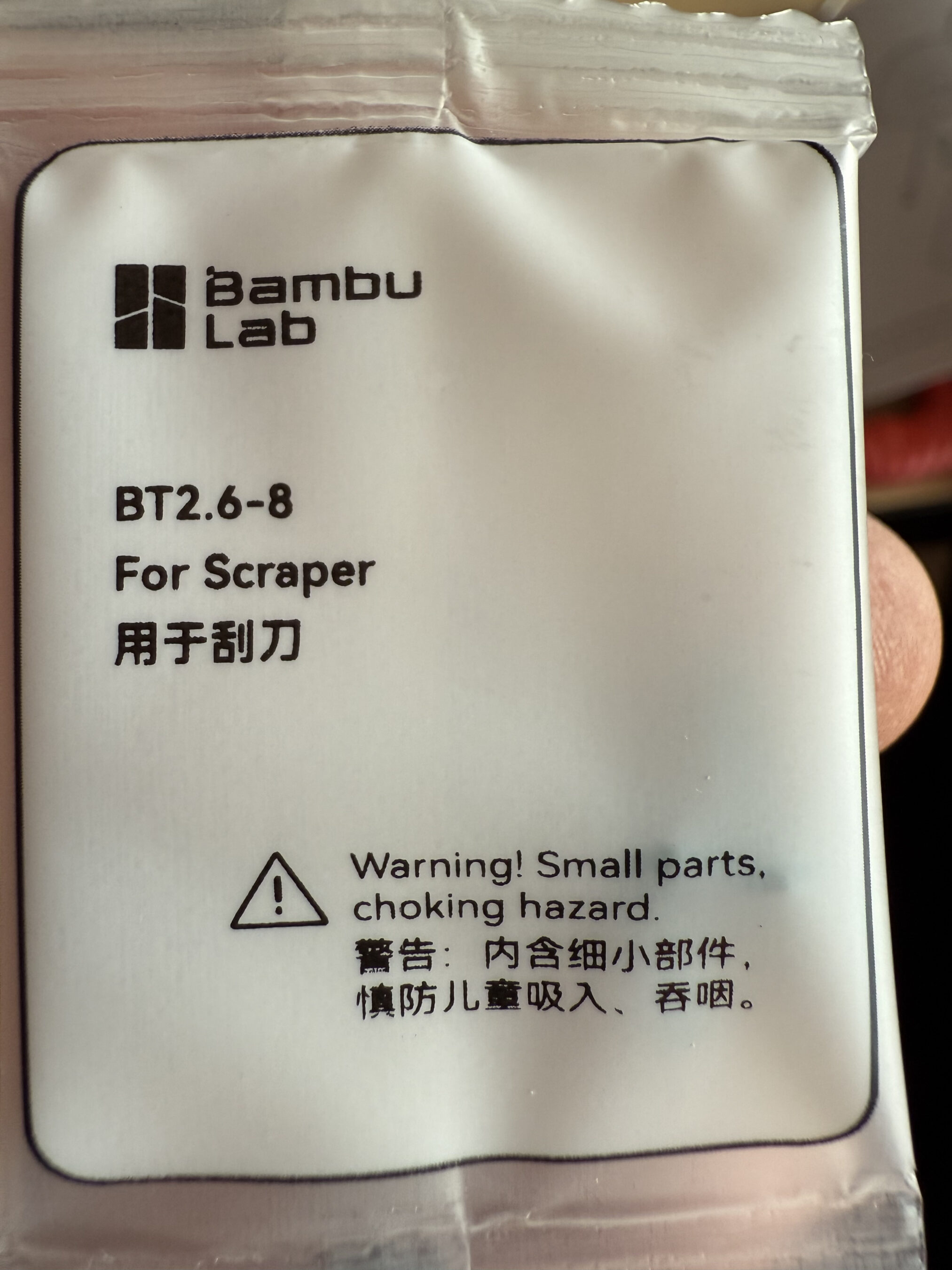
Another thing I really liked about Bambu Lab is that they supply you with screws for things that aren’t in the box, like the scraper screws shown above. At first I thought this was a bit weird but, in reality this makes complete sense as printing your own tool set is a great introduction to making your first prints.

Next I attacked the heavy box, this contained the 10 reels of filament I’d purchased at the same time. I’d ordered a good assortment of colours that would keep everyone in the family happy.

Installing the BambuStudio software on my MacBook Pro was a breeze. Using the account I setup at purchase time I was soon hooked into the Bambu Lab Makerworld community.

I immediately found the tools I needed to print and set about making my first 3D prints. The software has a lot of functionality, especially when it comes to the designing of your own objects. It’s fair to say the initial learning curve is vertical however, there are some great videos on YouTube on printing downloaded objects using the BambuStudio software.

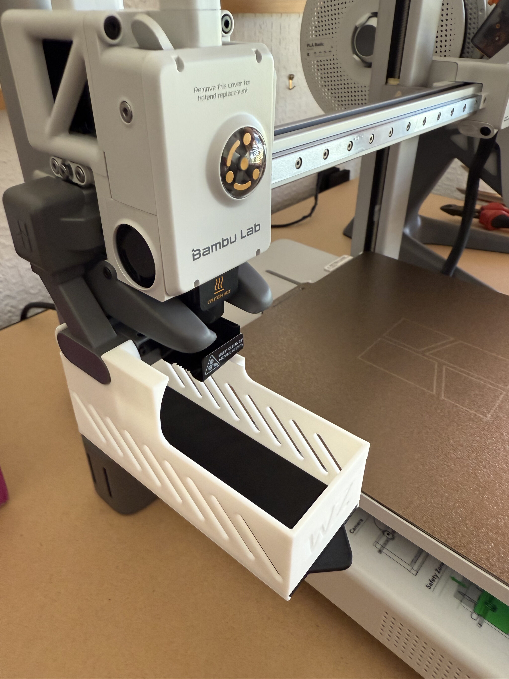
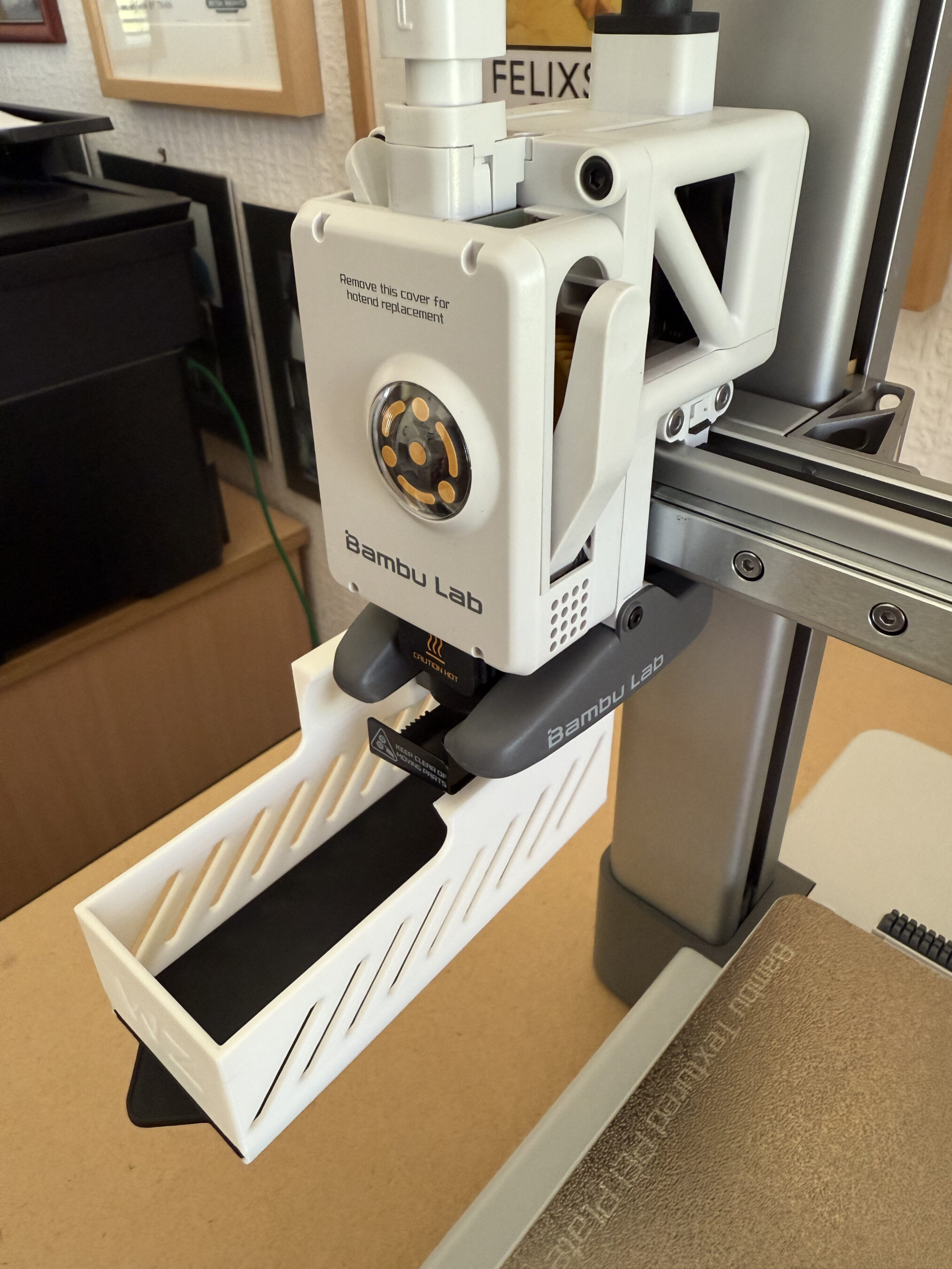
Whilst searching for 3D Print tools on the MakerWorld I stumbled across this really neat filament waste collector that fits nicely onto the X axis support. During the print there is a small amount of waste filament, especially if you are printing a multi-colour object as the print head has to be purged each time a new colour is required. Out the box there is nothing to catch the waste filament and so, it ends up on the floor. Fortunately the MakerWorld community resolved this issue with a multitude of options for collecting and storing the waste, all of which you can print yourself.

The print speed is incredibly quick, much quicker than I ever imagined and it’s addictive to stand and watch the print take form right in front of your eyes.

Printing an iPhone Stand for my sister-in-law

Once I’d printed the necessary tools and a few downloaded iPhone stands for the family I set about looking at designing my own objects.

The Bambu Studio software does have the capability to design objects built in but, the learning curve is vertical and there are very few videos on YouTube showing how to use the object creation section of the software. This lead me to look for an alternative 3D CAD package that had tutorials on how to create 3D print objects. After a little searching online i found that Tinkercad has a great range of tutorials online to get people started with designing their own 3D print objects.

In no time at all I had an account created on the tinkercad site and was going through the online tutorials to learn how to use all the functionality offered in the free tier.

TinkerCAD - Designing a cooling fan mount
TinkerCAD – Designing a cooling fan mount

The online tutorials are very good and move along at a good pace with interactive examples that show you how things work. Once I’d completed the tutorials I dived straight into designing some objects of my own.

I’ve still got a lot to learn about 3D printing but, I have to say that TinkerCAD really does simplify the whole design process. Once my object designs were complete, all I had to do was export them in .stl format and then import the STL file into Bambu Studio and send it to the printer.

So far my prints have come out great and I’ve been really impressed with the quality of the finished articles.

I’ve now started on my list of HAM Radio 3D print projects and will document my progress over the next few weeks and months as I progress.

More soon …

1946 Philips 170A-15 RadioBerry Receiver Project

Back in January 2025 I wrote an article about a little RadioBerry Project I’d started that was based around a very old Philips 170A-15 receiver from 1946.

The idea of the project was to build a nice shortwave receiver for the radio shack based around the RadioBerry HAT on a RaspberryPi 4 housed in a vintage receiver cabinet.

The project has taken longer than I imagined due to getting side-tracked by other projects that I already had ongoing.

1946 Philips 170A-15 Shortwave Receiver Internal View

With the original internals removed there’s plenty of room inside for the RadioBerry, RaspberryPi 4 and the small 15w audio amplifier. The audio is delivered via a pair of Celestion speakers that I had that were originally part of an old surround sound TV system.

Power distribution is achieved very simply using a multi-plug adapter that also has USB A connections in it. The whole thing is then powered via one 240v mains cable.

The screen fits over the original opening for the glass tuning display and is held in place by two mounting screws on the rear of the LCD panel.

I purchased some new speaker grill cloth from Amazon and remade the speaker grill front with cut outs for the speakers. It looks really tidy and matches the rest of the bakelite cabinet nicely.

1946 Philips 170A-15 Shortwave Receiver RadioBerry HAT on RaspberryPi 4

To finish the project off I need to purchase 3 rotary encoders so that I can have a VFO knob and two more knobs for other things (to be determined). The Volume control is already in place with the original knob fitted to it. It will be nice to complete the 4 knob line up.

1946 Philips 170A-15 Shortwave Receiver Rear Panel

I had to make a couple of fittings top and bottom to hold the original rear panel in place but, it worked out just fine and I only had to fit an SO239 antenna connector and ethernet RJ45 port so that it can be connected to my local LAN.

Receiving radio Caroline on 648Khz

The audio quality from the little RadioBerry and 15w amp is pretty good. With the speakers hidden nicely behind the refurbished speaker grill the project looks quite tidy!

It also makes a great receiver for the HAM bands with it’s coverage of 100Khz to 30Mhz.

The DL1YCF Enhanced fork of PiHPSDR works really well on the touchscreen and provides a modern control interface to the RadioBerry HAT.

Listening to the 20m HAM Band

I’ll drop a final article once I have purchased the 3 rotary encoders to fill the 3 remaining holes in the front of the cabinet.

More soon …

Home-Brew 12v DC Distribution Box

I’ve been wanting to tidy up the cabling to the 12v DC PSU for some time in the radio shack as like many HAMs I have a number of radios/devices that all need a 12v feed but, only two connectors on the front of the PSU. The net result was a birds nest of wires all connected to the PSU making it impossible to disconnect one device without others getting disconnected at the same time.

Looking online I found that many of the HAM outlets stores sell nice little 12v DC distribution boxes that would be ideal however, they’re all priced somewhat high for what they are so, I decided to purchase the parts and make one myself.

Searching on Amazon I found all the necessary parts for less than a quarter of the cost of commercially made units. A couple of days later the parts arrived and sat on my desk in the shack for a few weeks. Yesterday I finally found the time to make a start on the project.

M0AWS home-brew 12v DC Distribution Box

After much drilling and filing I had the necessary holes/slots cut in the plastic box for the 4mm connectors and fuse holders and started wiring them up. Part way through my 30 year old soldering iron decided to die and so I had to stop and wait for a replacement to arrive.

M0AWS completed 12v DC Distribution Box

With the new soldering iron in hand it only took 30mins or so to complete all the joints and I soon had the box together ready to test with my multimeter to ensure I didn’t have any shorts or crossed wires.

With testing complete and fuses in place I connected it up to the PSU and then connected all the devices one by one checking for voltage drops as I went.

M0AWS 12v DC Distribution Box

I now have my CG3000 remote auto ATU, GPSDO, QO-100 ground station and IC-705 all nicely connected in a much tidier fashion than before, all for considerably less than the commercially available alternatives.

More soon …

13m Multiband Vertical Antenna – 18 Month Summary

Following on from the article I wrote about the performance of my multi band vertical antenna I’ve now put together a table showing it’s performance on each band as experienced over a period of 18 months.

It’s interesting to note the antenna wavelength measurements on each band as 13m (43FT) seems to be an almost perfect length for a simple multi band vertical HF antenna with excellent DX capabilities.

M0AWS 13m (43FT) Multiband Vertical HF Antenna Info
M0AWS 13m (43FT) Multiband Vertical HF Antenna Info (Click to Enlarge)

Looking at the information you can see that performance on the 160m band is poor. This is to be expected as the antenna is far too short for a band with such a long wavelength. I knew this would be the case from the outset and never planned to use this antenna on the 160m band. I’ve included the data here just for completeness. If you’re looking for a reasonable 160m band antenna that can fit into an average UK garden then take a look at my Inverted-L antenna article.

Performance on the 80m band is surprisingly good considering the antenna is only 1/6th of a wavelength long. With contacts into Indonesia achieved using relatively low power levels this antenna surprised me with its performance on the 80m band. A 1/4 wavelength antenna would of course perform better but, like all multi band vertical antennas for the HF bands there is always a compromise.

On the 60m band the antenna is pretty much a 1/4 wave vertical, it works great on this band and I’ve had a lot of fun chasing DX in the winter months. With the longest contact being into Brazil at 6144 miles this antenna performs extremely well for such a simple design.

On the 40m band performance is better still. With the antenna being just over a 1/4 wavelength long the point of max current is above ground level making this a very good DX antenna. With multiple contacts into Australia at distances over 10,000 miles this antenna is the ideal 40m band DX chaser for small gardens.

Moving up onto the 30m band this antenna now begins to really shine. Being a half wave long on 30m the point of max current is half way up the wire lowering the angle of radiation considerably. This results in excellent global coverage with contacts into Australia being a breeze. With the longest distance achieved being 11,776 miles into New Zealand this really is the goto antenna for fans of the 30m band with small gardens. This antenna easily out performs my 30m band Delta Loop design whilst giving better global coverage.

On the 20m band this antenna performs very well indeed. Considering it’s 3/5th of a wavelength long which is a strange length to have, it’s no slouch. Global coverage is excellent and working into Australia is relatively easy. I’ve yet to work into New Zealand on the 20m band using this antenna but, that’s mainly due to me not being on air at the right times. Best distance worked so far on this band is 10,656 miles.

On the 17m band the antenna is 3/4 wavelength long. This is a very useful length and easy to tune as it presents pretty much 50 ohm impedance at the feed point. Performance is simply stunning on 17m, if you can hear the DX you can work them. I am amazed at how well this antenna works on this band. It seems to have a low angle of max radiation making it excellent for chasing DX stations. Giving me my first contacts into Alaska and New Zealand this is my goto antenna for the 17m band.

On the 15m band this antenna is 7/8th of a wavelength long. Performance doesn’t feel as good as it does on 17m but, with the longest distance achieved being 8023 miles there’s really no reason to doubt it. With only 87 contacts being made on this band due to the fact that I always get trapped chasing DX on the 17m band and never make it any further up the bands, I’m sure this antenna will perform extremely well long term on 21Mhz. I just need to make more effort to get on this band.

The 12m band is one of the bands I didn’t expect this antenna to perform well on.
Being 1 and 1/8th wavelengths long it’s not a length that you would normally consider using for an antenna however, performance is excellent. This is most likely due to the point of max current being a fair way up the wire resulting in a low angle of maximum radiation. DXing is great fun with this antenna on the 12m band and it’s surprised me time and time again at how easily I’ve been able to work DX stations. With the best distance worked so far being into the Falkland Islands at 7973 miles, this antenna has huge potential on this band. Like the 15m band, I need to make an effort to spend more time on the 12m band and see how far I can push this antenna.

Finally we reach the dizzy heights of 28Mhz on the 10m band where the antenna is 1 and 1/4 wavelengths long. Again this is a useful length as it presents almost 50 ohm impedance at the feed point. DX performance on the 10m band is good. It’s probably very good however, like the 15m and 12m bands, I rarely make it up onto the 10m band and so I’ve not really given the antenna the time to prove itself at 28Mhz. My best distance worked so far on this band is 4872 Miles into the USA but, I’m sure I could easily do better if I committed more time to it.

I’ve pretty much covered all the good points of this simple multi band antenna so, now let’s look at the not so good points.

If you’re in the UK and are looking to work other UK stations then this antenna isn’t for you. Like all vertical antennas there isn’t much in the way of NVIS radiation and so you’ll find UK stations just won’t hear you. You’ll also often find you won’t hear UK stations at all due to the null at the top of the antenna that attenuates signals arriving from high/very high angles. For me this is fine as I wanted an antenna that was focused on DXing as much as possible.

From 10Mhz upwards the antenna also isn’t that good for working stations in nearby Europe. Most of the time you will only hear European stations that are more than 1000 – 1500 miles away, anything closer just doesn’t appear in the receiver. On the 15m and 12m bands often you will never hear European stations at all, only DX stations. This does of course reduce the QRM from UK/EU stations considerably making it easier to work those weak/QRP DX stations.

So as you can see, 13m (43FT) of vertical wire is probably one of the best lengths you can possibly use for a multi band vertical HF antenna especially if like me, you have a small garden to squeeze your antennas into. I don’t like to say it but, this could be the magical length we’re all looking for when making a multi band HF vertical antenna.

Tuning of the 13m (43FT) vertical antenna is achieved using my CG3000 remote auto ATU. I initially started off using my home-brew Pi-Network ATU but, changed over to the CG3000 so that in the winter months I don’t have to run out into the rain and wind to change bands. It’s important to note that the ATU must be at the base of the wire and not in the radio shack. It’s also important to note that I have 4 x 20m long radials connected to the CG3000 along with an earth spike at the base of the wire. This combination of ground and tuner works incredibly well with the ATU tuning on each band with ease in less than 3 seconds. I’ve also not had any issues with the CG3000 attempting to retune whilst in the middle of a QSO, once it’s initially tuned it doesn’t retune again until I either change band or make a large change in frequency.

The achieved SWR on all bands is <1.5:1 except for 160m where it is 1.8:1.

More soon …

Modelling my Inverted-L Antenna

Since I put together my Inverted-L antenna and Pi-Network ATU I’ve been having a lot of fun on the low bands.

Getting back onto 160m has been most enjoyable and I’ve now had over 100 ‘Top Band’ contacts with distances covered as far as 3453 Miles into Sosnovoborsk Asiatic Russia.

I must admit I am amazed at the distances achieved on the 160m band as the antenna isn’t very high above ground level when compared to a single wave length on 160m.

M0AWS Inverted-L Antenna View

The Inverted-L antenna at the M0AWS QTH was designed purely around the size of the back garden. Using a couple of 10m Spiderpoles the vertical section of the antenna is 10m tall and the horizontal section is 28m long. Naturally the antenna resonates around 2.53Mhz but, can be tuned to resonate anywhere on any band using the Pi-Network ATU I built that is situated at the base of the vertical section of the antenna.

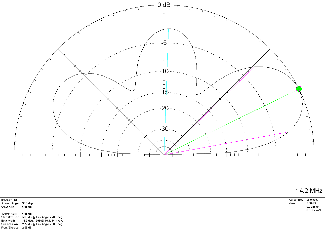
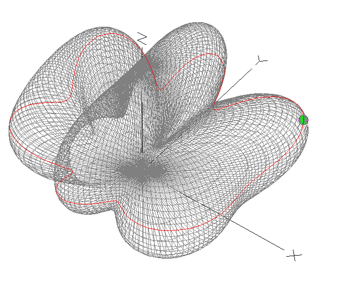
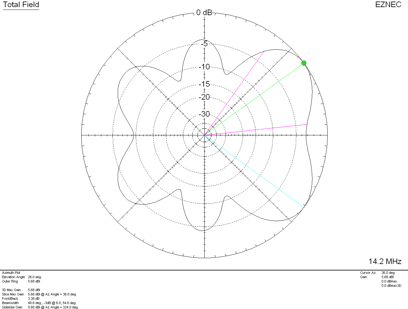
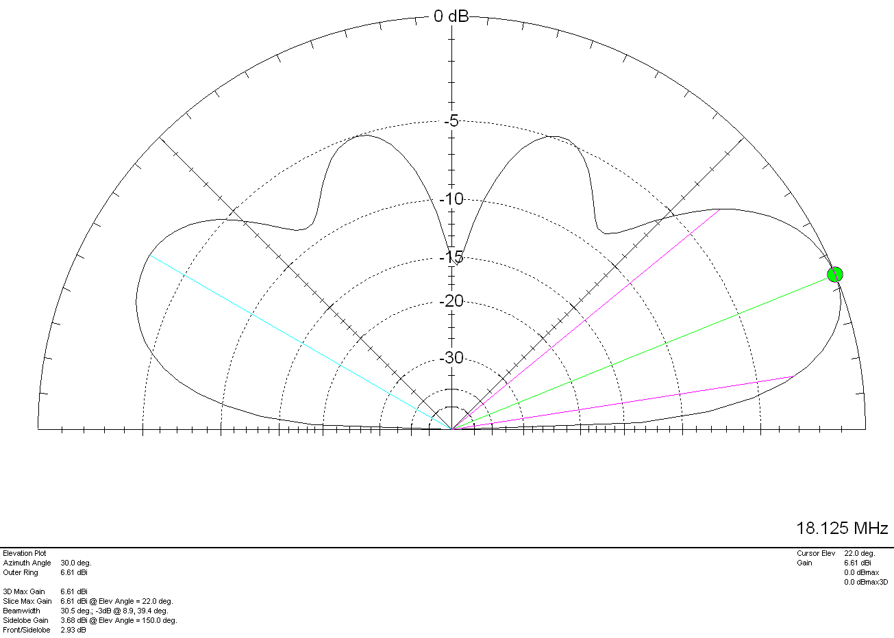
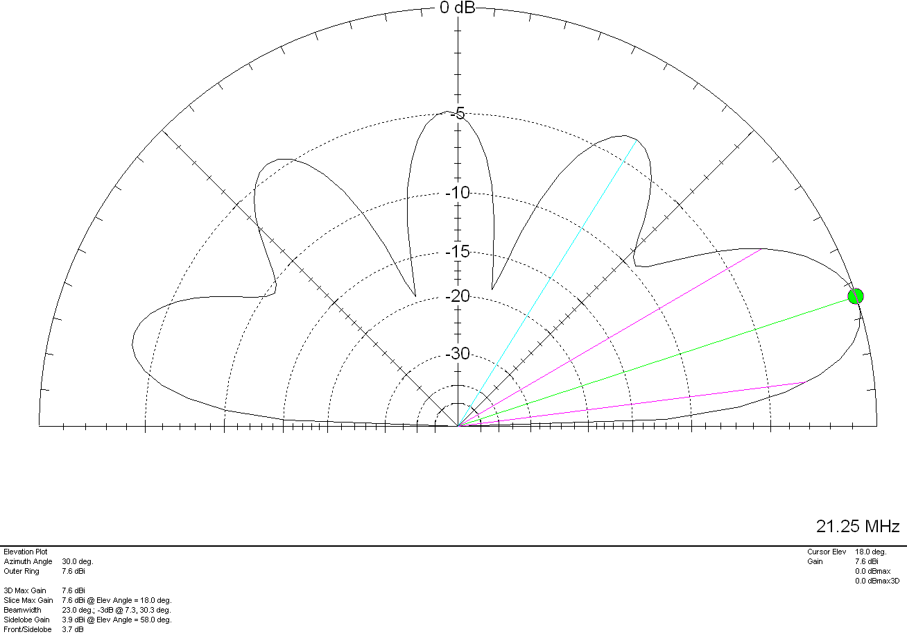
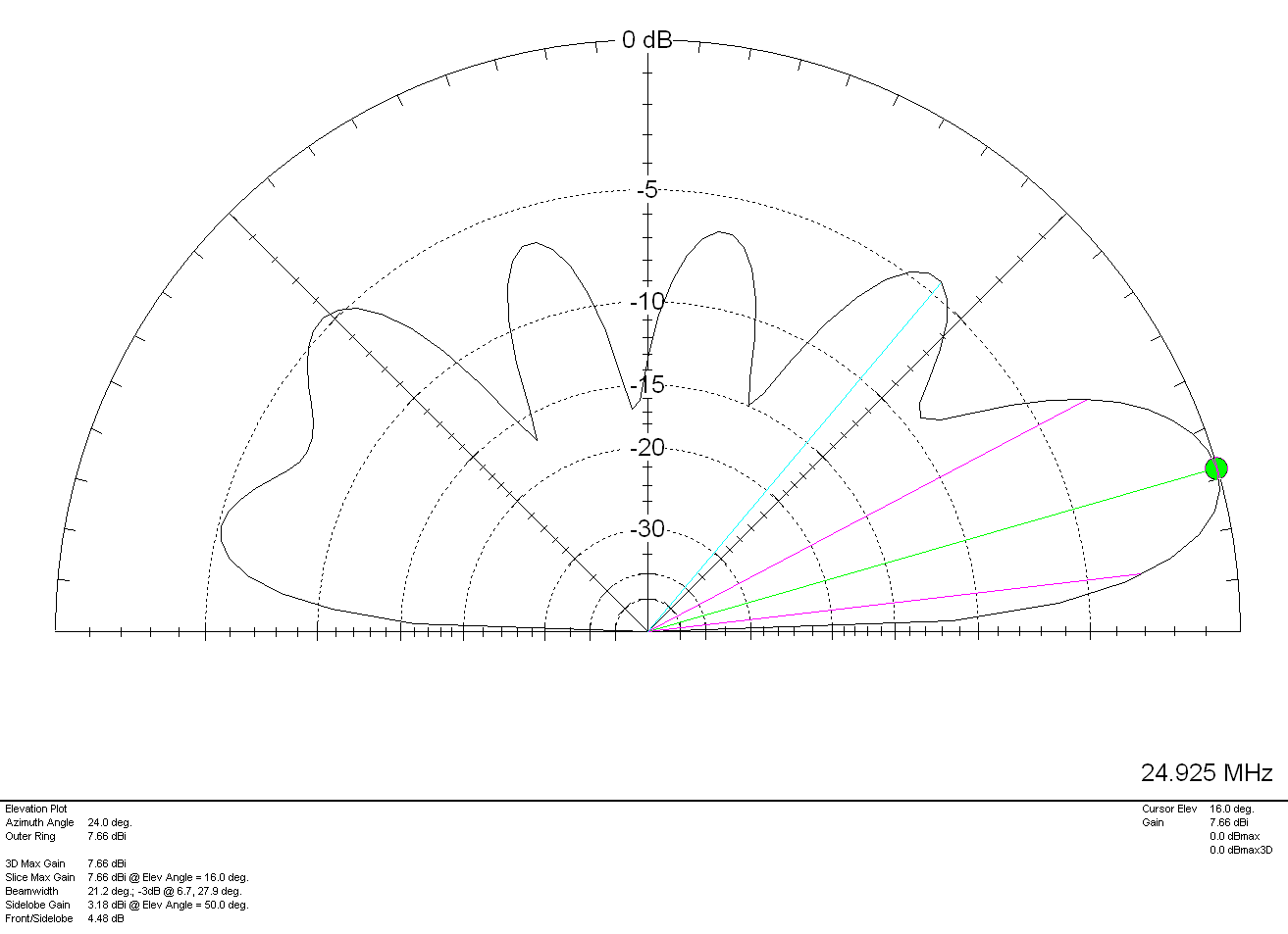
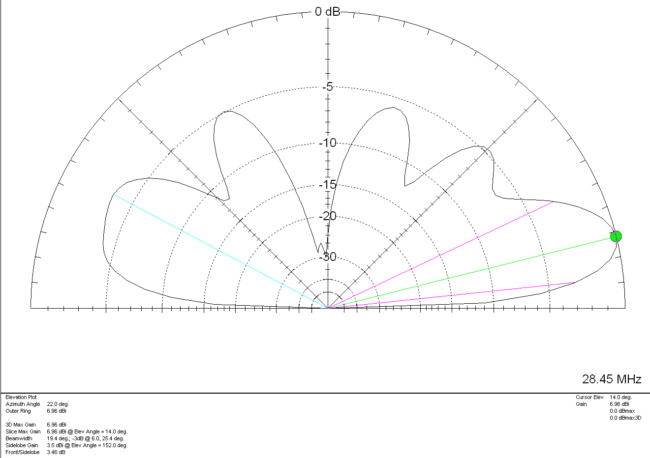
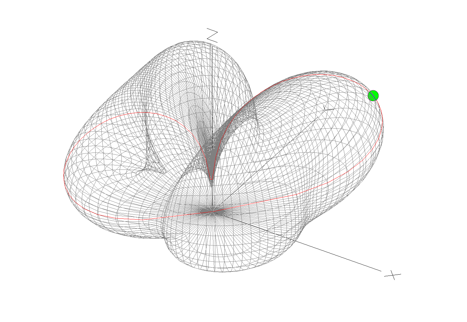
Looking at the far field plots for the antenna on each band we see that as we move higher in frequency the radiation pattern becomes more complex and the radiation angle gets lower, exactly what we would expect from such an antenna. The antenna runs pretty much North/South in the garden ( X axis on the diagram above) and so we would expect the antenna to radiate East/West (Y axis on the diagram above) however, this isn’t always the case.

(Click Far Field Plots for full screen view)

On 160m the antenna favours the South (-X Axis) and presents some usable high angle gain although, from using the antenna you would never know this to be the case as it seems to have pretty good all round coverage. With the best distance of 3453 Miles being covered to the East into Asiatic Russia the antenna performs well even though the far field plot is slightly biased to the South.

On the 80m band the Inverted-L antenna becomes a cloud warmer and exhibits very high angle radiation. On 80m the antenna is ideal for NVIS Inter-G propagation and is great for rag chewing with other UK/Near EU stations.

Looking at the far field plots for the 60m band once again the antenna provides lots of high angle gain however, there is also some very useable lower angle gain that has proven to be excellent for working long hauls into North America and east into Central Asia. On the 60m band during the day the antenna is excellent for Inter-G chatting, using just 20w-40w I can very easily chat with other UK HAMs even when the band is noisy.

Moving on up to the 40m band we find the far field plot starts to get a little more complex. Looking at the 3D plot you’d think that the antenna favoured the South (-X Axis) however, in reality it favours the NorthWest with both some high and low angle gain. This antenna has proven to be excellent for DXing into North America on 40m but, has also been great for DXing into South America getting great signal reports from stations in Panama at a distance of 5415 Miles. During the day NVIS propagation is excellent and I find I can chat with other UK and near EU stations with ease using just 25w.

M0AWS Inverted-L Antenna 60m/40m Global Coverage

Above is a screen shot from PSKReporter showing stations that have heard me on the 40m and 60m bands. As you can see, global coverage is excellent with stations as far as Australia and New Zealand hearing me on the 40m band and stations on the West Coast USA hearing me on the 60m band. I was also pleased to see I was heard in Africa on both bands, a region of the world I would like to get more contacts from.

On the 30m band the Inverted-L antenna starts to exhibit two lobes with gain to the NorthEast and NorthWest. This makes the antenna ideal for working into the USA and Australia/New Zealand over the North Pole. Working US stations is a breeze with relatively low power and I almost got a contact with New Zealand during the evening greyline but, unfortunately the DX station dropped out before I managed to get my signal report back to him. As time goes on I’m sure the antenna will more than prove itself on the 30m band.

So far I’ve not ventured above the 30m band with the Inverted-L antenna as I’ve really been enjoying access to Inter-G chats on 80m, 40m and 60m and chasing DX on 160m, 60m, 40m and 30m. I need to venture up onto the higher bands before the long winter nights settle in and the higher HF bands close for the winter season.

Looking at the far field plots on the higher HF bands the antenna has huge potential as it provides some nice low angle radiation in useful directions.

On the 20m band the far field plot starts to get much more complex with lobes at many different angles. The main gain lobe is to the NorthEast towards the USA and is at a fairly low angle and so this antenna should be great for working stateside on the 20m band. There are also lobes to the NorthEast and so hopefully working VK/ZL over the pole should also be possible. As I said above I’ve not yet used the antenna above the 30m band and so at this time cannot confirm performance but, it looks promising.

The 17m band also looks promising with a similar far field plot as the 20m band but, with lower angle of maximum radiation and more gain. It will be very interesting to test this antenna on 17m especially since the noise level is below S0 and I can very easily hear the weakest of stations on this band.

Once again the 15m band looks very similar to the 17m band, low angle radiation but, with a slightly more complex far field plot.

The 12m band far field plots continue the theme with the angle of maximum radiation slightly lower than on the 15m band and slightly more gain. This antenna should be great for chasing the DX on the very quiet 12m band.

Finally the 10m band is very similar to the 12m band in that the far field plots show low angle gain albeit with an even more complex radiation pattern.

I originally put this antenna up so that I could work Inter-G on the low bands but, it has proven to be a much more worthy antenna than I originally thought it would be. I need to spend more time with this antenna on the bands above 30m to really see how it performs on the higher HF bands but, so far I’m really pleased with it’s overall performance on all the bands tested to date.

I can highly recommend using FT8 to test new antennas. With PSKReporter and my own NodeRed World Map WSJT-X interface I can see realtime the antenna performance on each band. FT8 is an extremely useful tool when it comes to testing antennas to see if they perform as per the modelling and can often provide some performance surprises!

More soon …

20m Band Delta Loop Antenna

I’ve had this antenna model for ages now but, never got round to putting it onto the website until Alex, GM5ALX was talking about making one the other day whilst chatting on the QO-100 satellite.

The 20m band delta loop follows exactly the same design principles as all the other delta loop designs I’ve already put on the website. They are designed such that they present a 50 ohm impedance at the feed point and thus have no requirement for complex impedance matching circuits/transformers.

M0AWS 20m Band Delta Loop Antenna - Antenna View
M0AWS 20m Band Delta Loop Antenna – Antenna View

The dimensions for the antenna are as follows:

Wire 1 – Horizontal exactly 1m above the ground for its entire 10.2m length.
Wires 2 & 3 are exactly 6.18m long each with the top being 4.5m above the ground.

M0AWS 20m Band Delta Loop Antenna - 3D Far Field Plot
M0AWS 20m Band Delta Loop Antenna – 3D Far Field Plot

The 3D far field plot shows a typical delta loop radiation pattern with the maximum radiation through the loop and a deep null in the centre.

M0AWS 20m Band Delta Loop Antenna - 2D Far Field Plot
M0AWS 20m Band Delta Loop Antenna – 2D Far Field Plot

The 2D elevation plot shows that the antenna will give a maximum gain of -0.79dBi at 30 degrees when used over average/poor soil types. If like me you use your Delta Loop antennas on the beach then the antenna will present considerably more gain as it will benefit from the salt water reflection.

If you want to lower the angle of maximum radiation and increase the gain over average ground just raise the antenna up so that the top is around 7m above ground. This will give a much lower angle of radiation and improve the gain figure by 2-3dBi. Don’t forget that if you raise the antenna the point of resonance will also rise in frequency and so you may need to shorten the wires a little to get the point of resonance back to where you want it.

The SWR plot shows that the antenna will have a fairly wide bandwidth and match to 50 ohm coax extremely well. The antenna is designed to be fed in one of the lower corners via a 1:1 balun for best results.

M0AWS 20m Band Delta Loop Antenna - SWR Curve
M0AWS 20m Band Delta Loop Antenna – SWR Curve

Summary:

Total Wire Length: 22.56m
Horizontal Wire Length: 10.2m @ 1m above ground
Diagonal Wire Lengths: 6.18m
Wire Dia: 2.5mm
Height at Centre: 4.5m
Feed Type: 1:1 Balun in bottom corner (Can use coax if necessary)
Impedance: 50 Ohm
SWR: <1.5:1 at resonance