QO-100 Satellite Ground Station Complete Build

I get quite a few emails from readers of my blog asking how my QO-100 satellite station is put together and so, I thought perhaps now is a good time to put together an article detailing the complete build.

My QO-100 satellite ground station is built around my little Icom IC-705 QRP transceiver, it’s a great little rig and is ideal for the purpose of driving a 2.4Ghz transverter/up-converter.

Of course all the software used for the project is Opensource and freely available on the internet.
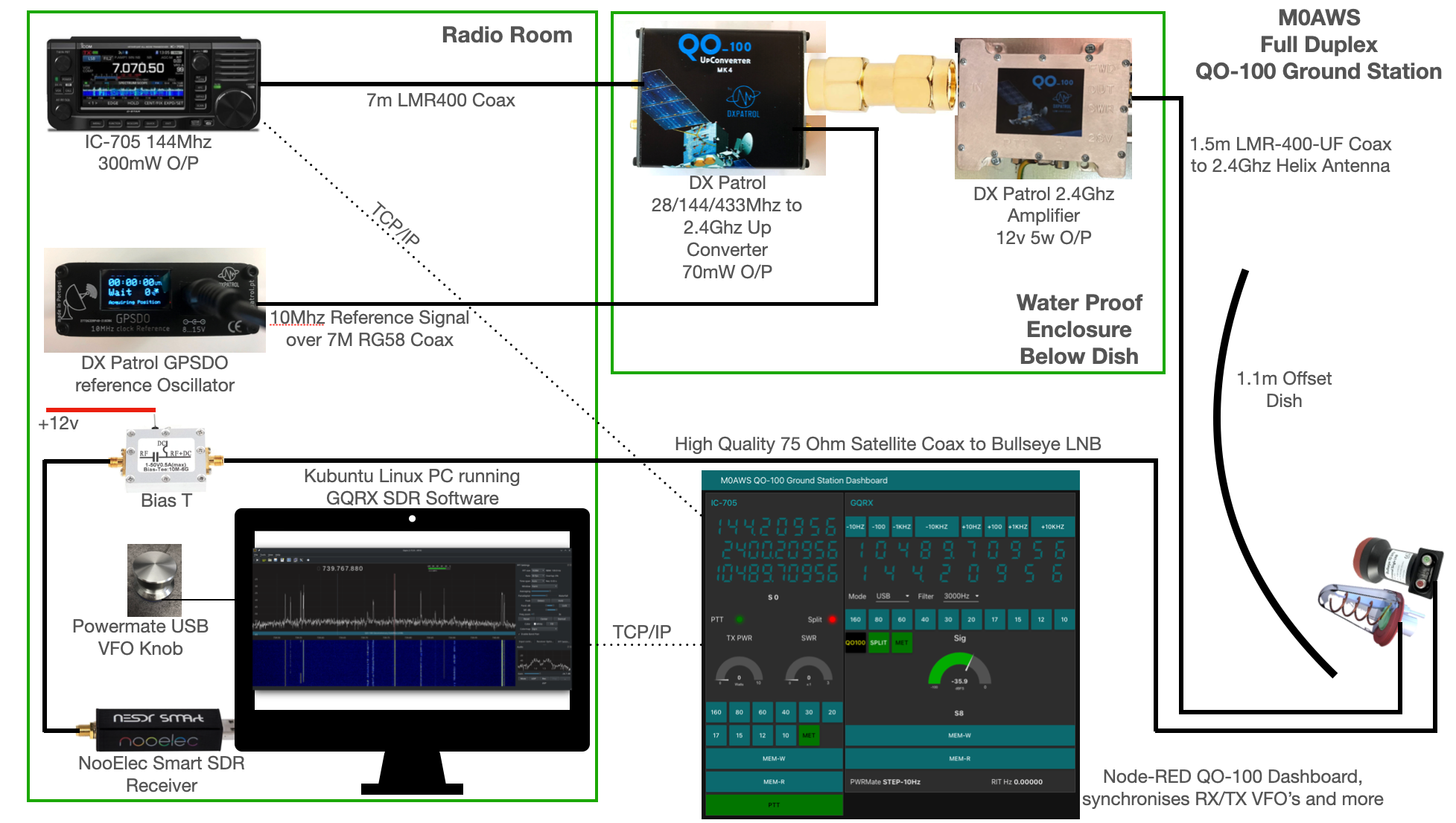
M0AWS QO-100 Ground Station Build Visual
M0AWS QO-100 Ground Station Build Visual (Click to Enlarge)

The station comprises of the following building blocks:

  • Icom IC-705 Transceiver
  • DXPatrol 28/144/433Mhz to 2.4Ghz Up-Converter
  • DXPatrol GPSDO Reference Oscillator
  • DXPatrol 2.4Ghz 5/12w Amplifier
  • Nolle Engineering 2.2 turn 2.4Ghz IceCone Helix Antenna
  • 1.1m (110cm) Off-set Dish
  • Bullseye 10Ghz LNB
  • Bias-T to feed 12v to LNB
  • NooElec SmartSDR Receiver
  • PC Running Kubuntu Linux Operating System
  • GQRX SDR Opensource Software
  • Griffin Powermate USB VFO Knob
  • QO-100 Ground Station Dashboard developed using Node-RED
  • LMR400-UF/RG58 Coax Cable
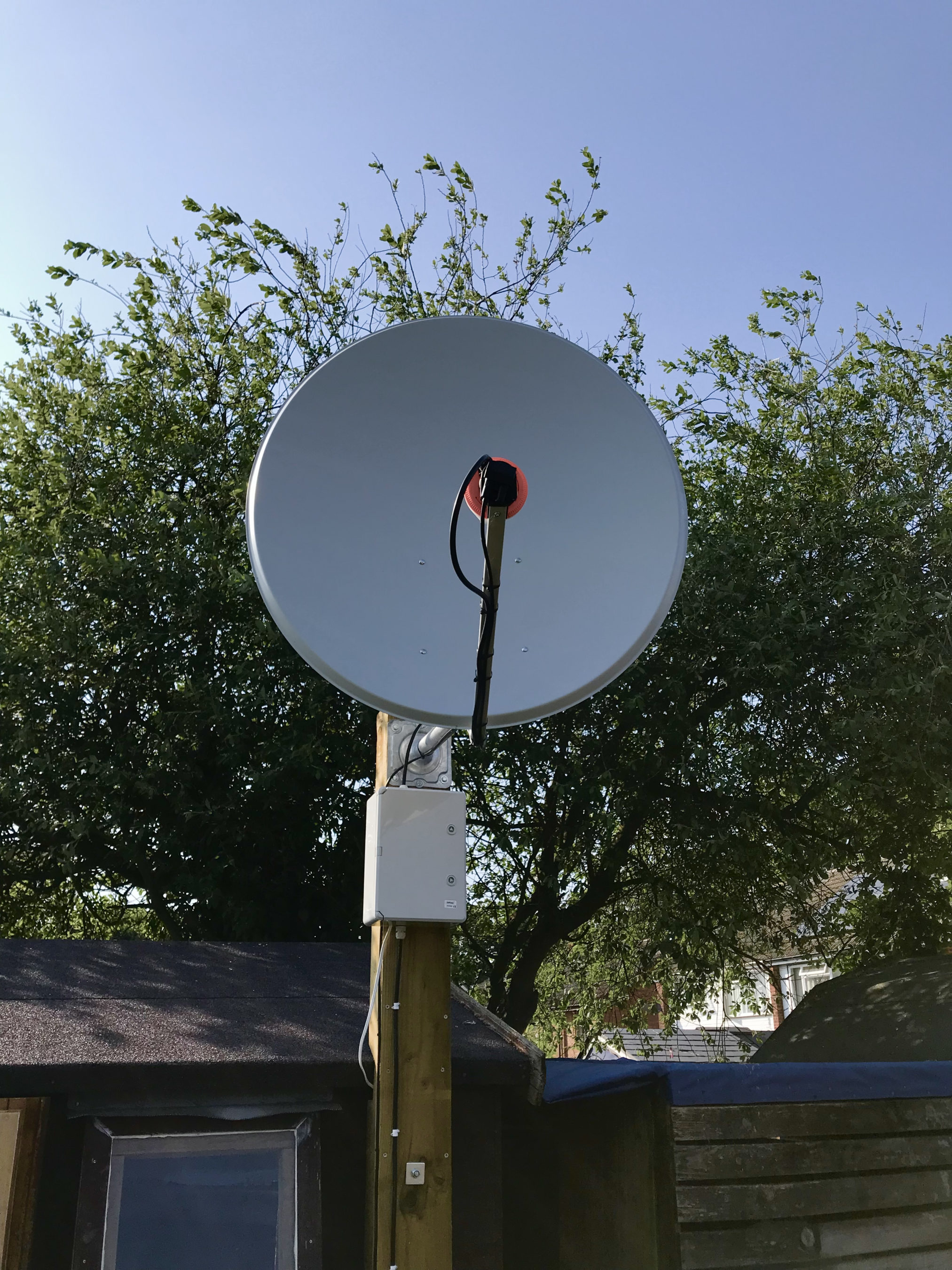
M0AWS QO-100 1.1m off-set Dish and IceCone Helix antenna ground station
M0AWS QO-100 1.1m (110cm) off-set Dish with IceCone Helix antenna and Bullseye LNB.

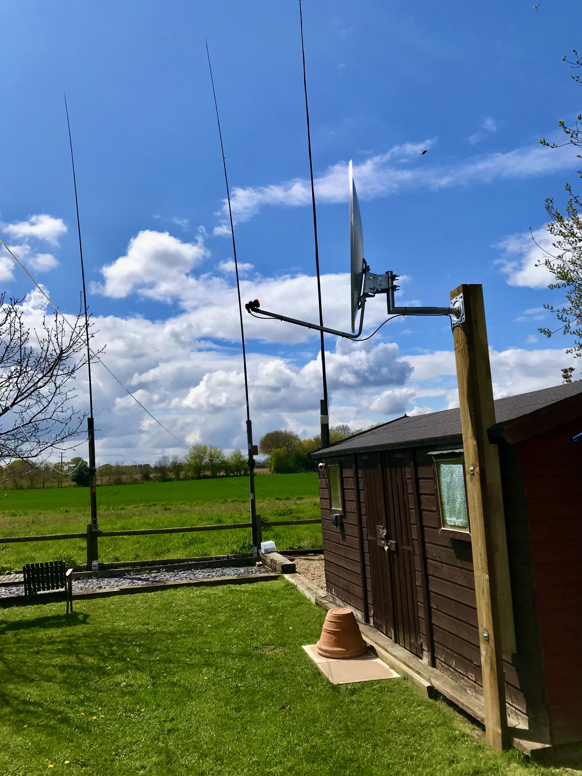
To get a good clear view of the QO-100 satellite I have the dish mount 3.2m above the ground. This keeps it well clear of anyone walking past in the garden and beams the signal up at an angle of 26.2 degrees keeping well clear of neighbouring gardens.

The waterproof enclosure below the dish houses all the 2.4Ghz equipment so that the distance between the feed point and the amplifier are kept to a minimum.

The DXPatrol amplifier is spec’d to run at 28v/12w or 12v/5w, I found that running it at 28v produced too much output for the satellite and would cause the LEILA alarm on the satellite to trip constantly. Running the amp at 12v with a maximum of 5w output (average 2.5-3.5w) is more than enough for me to have a 5/9+10 signal on the transponder.

The large 1.1m dish gives me quite an advantage on receive enabling me to hear the very weak stations with ease compared to other stations.
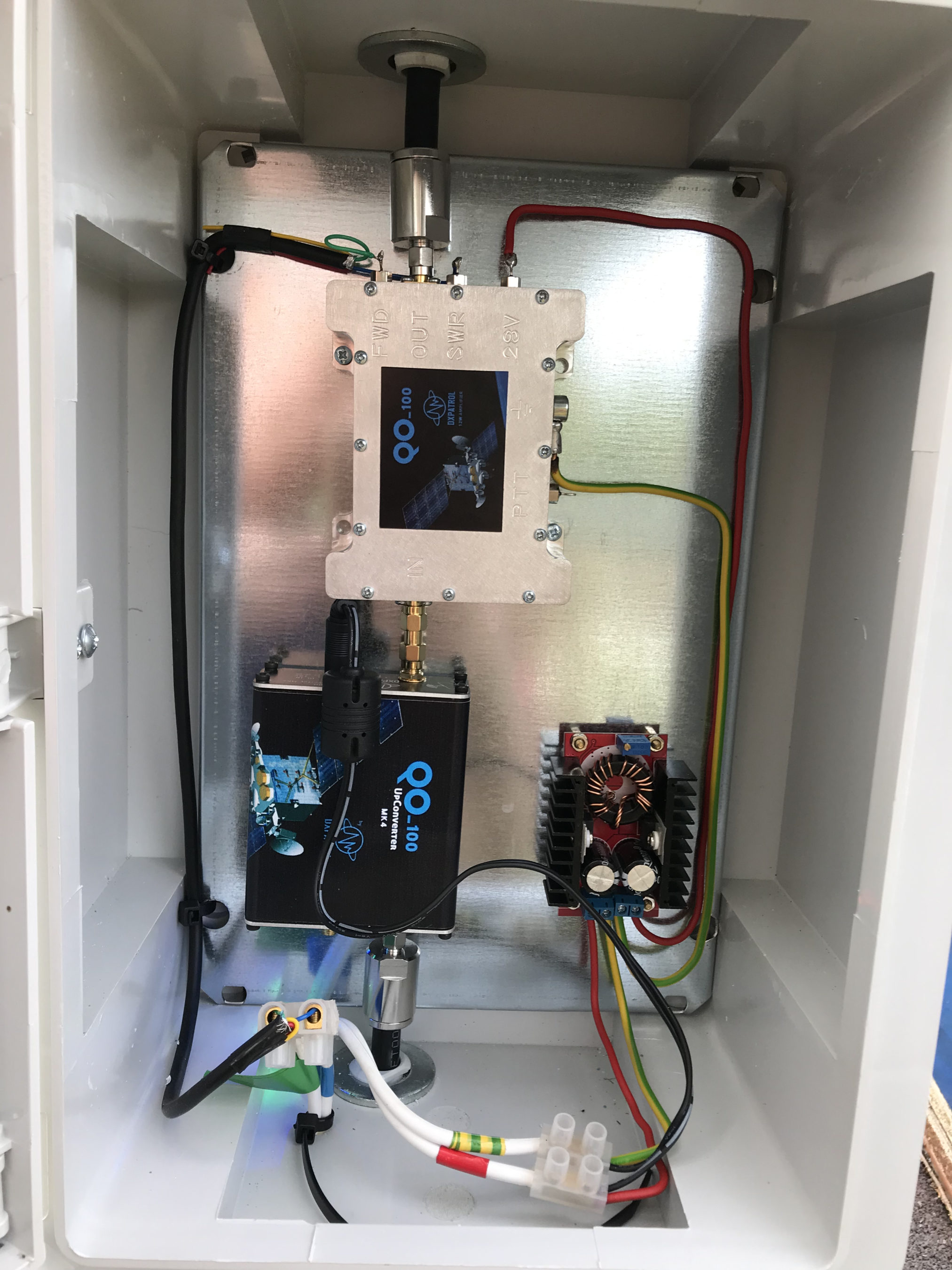
2.4Ghz ground station enclosure ready for testing

The photo above shows the 2.4Ghz equipment mounted in the waterproof enclosure below the dish. This photo was taken during the initial build phase before I rewired it so, the amplifier is shown connected to the 28v feed. To rewire the amp to 12v was just a matter of removing the 28v converter and connecting the amp directly to the 12v feed instead. This reduced the output from a maximum of 12w down to a maximum of 5w giving a much better (considerate) level on the satellite.

It’s important to keep all interconnects as short as possible as at 2.4Ghz it is very easy to build up a lot of loss between devices.

For the connection from the IC-705 to the 2.4Ghz Up-Converter I used a 7m run of
LMR-400 coax cable. The IC-705 is set to put out just 300mW on 144Mhz up to the 2.4Ghz converter and so it’s important to use a good quality coax cable.

Once again the output from the 2.4Ghz amplifier uses 1.5m of LMR-400-UF coax cable to feed up to the 2.2 turn Icecone Helix Antenna mounted on the dish. This keeps loss to a minimum and is well worth the investment.
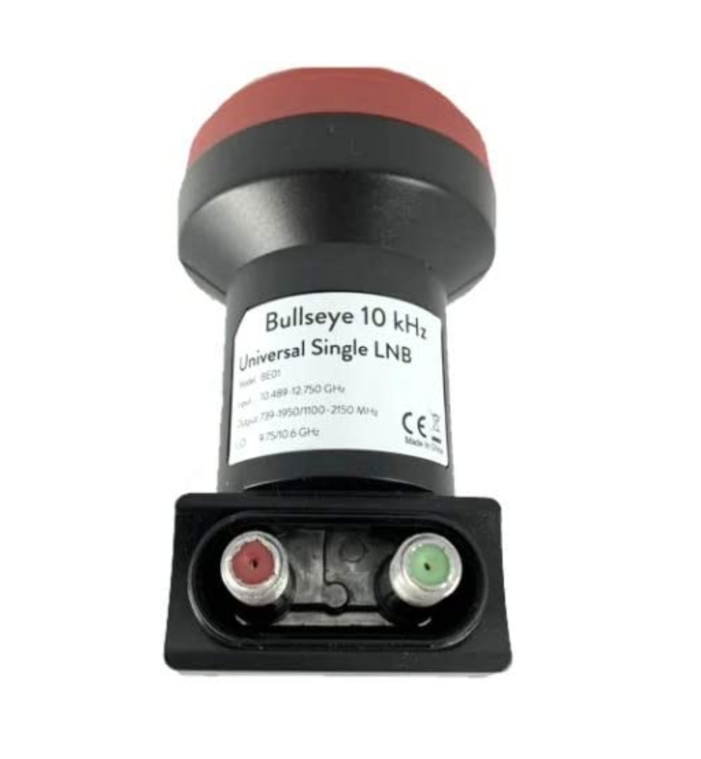
Bullseye 10Khz High Stability Unversal Single LNB for 10.489-12.750Ghz

The receive path starts with a Bullseye LNB, this is a high gain LNB that is probably one of the best you could use for QO-100 operations. It’s fairly stable frequency wise but, does drift a little in the summer months with the high temperature changes but, overall it really is a very good LNB.

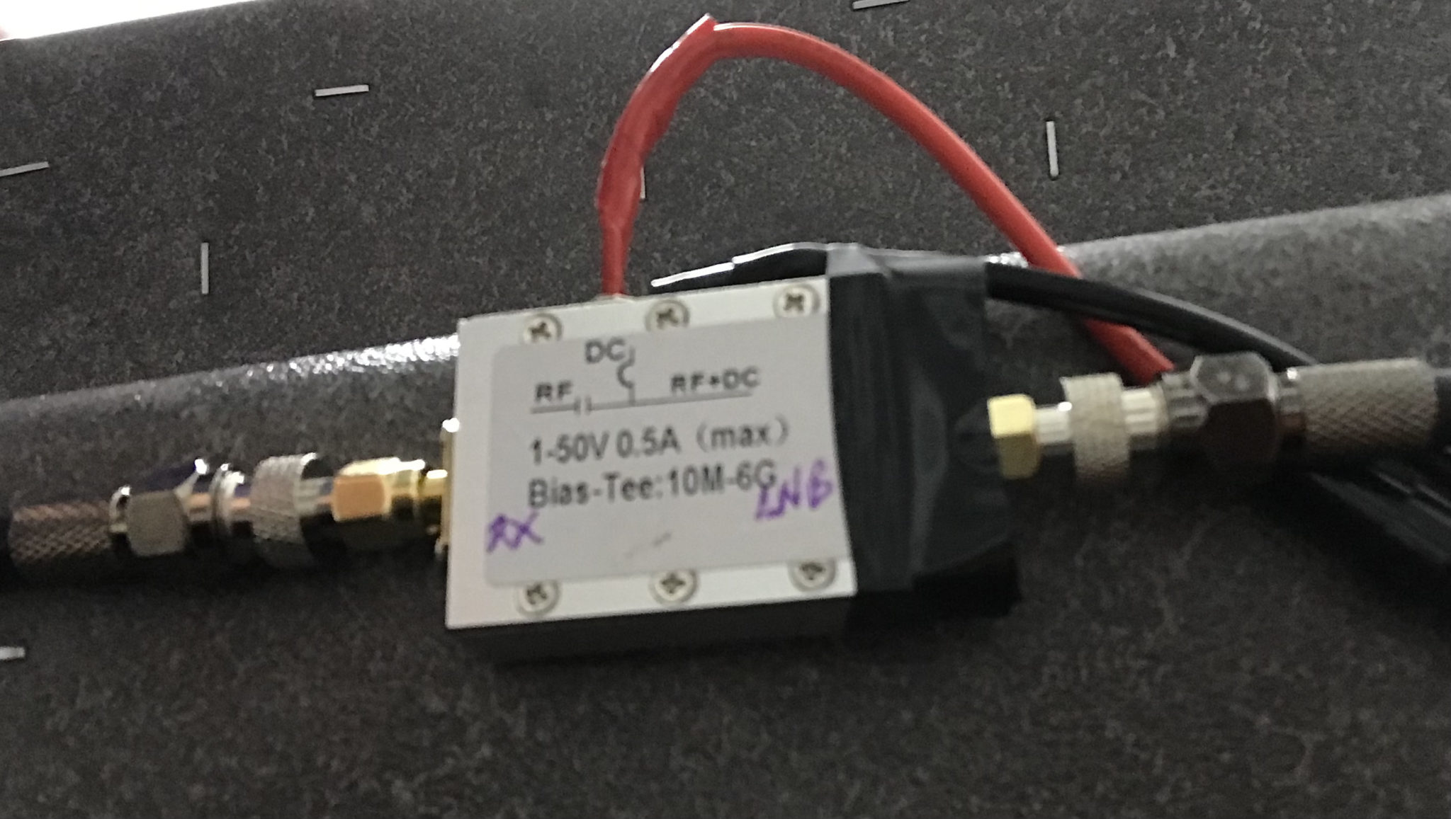
The 12v feed to the LNB is via the coax and is injected by the Bias-T device that is in the radio shack. This 12v feed powers the LNA and associated electronics in the LNB to provide a gain of 50-60dB.
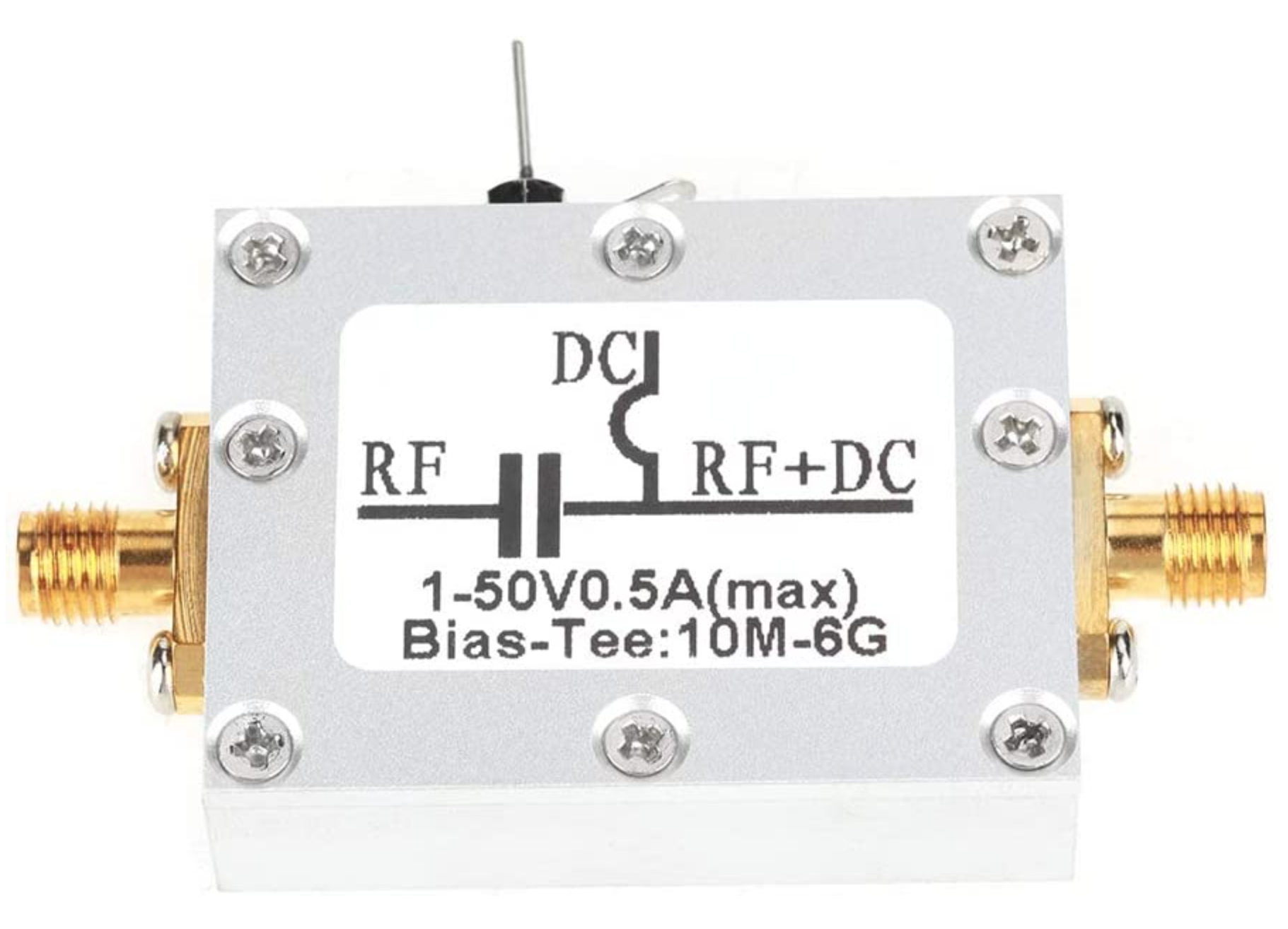
Bias-T to inject 12v feed into the coax for the Bullseye LNB

From the Bias-T the coax comes down to the NooElec SmartSDR receiver. This is a really cheap SDR device (<£35 on Amazon) based on the RTL-SDR device but, it works incredibly well. I originally used a Funcube Dongle Pro+ for the receive side however, it really didn’t handle large signals very well and there was a lot of signal ghosting so, I swapped it out for the NooElec SDR and haven’t looked back since.

The NooElec SmartSDR is controlled via the excellent Opensource software GQRX SDR. I’ve been using GQRX SDR for some years now and it’s proven itself to be extremely stable and reliable with support for a good number of SDR devices.

To enhance the operation of the SDR device I have added a Griffin Powermate VFO knob to the build. This is an old USB device that I originally purchased to control my Flex3000 transceiver but, since I sold that many moons ago I decided to use it as a VFO knob in my QO-100 ground station. Details on how I got it working with the station are detailed in this blog article.

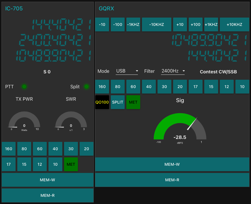
Having the need for full duplex operation on the satellite this complicates things when it comes to VFO tracking and general control of the two radios involved in the solution and so I set about creating a QO-100 Dashboard using the great Node-RED graphical programming environment to create a web app that simplifies the management of the entire setup.
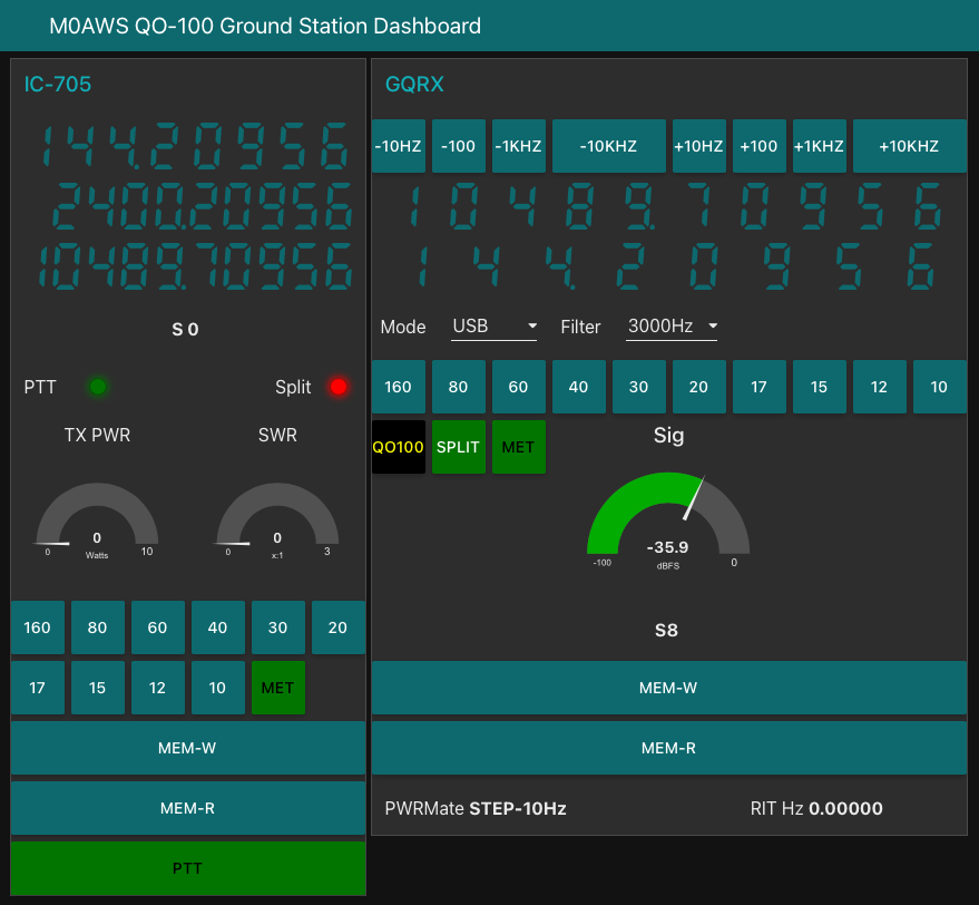
M0AWS QO-100 ground Station Control Dashboard built using Node-RED.

The QO-100 Dashboard synchronises the transmit and receive VFO’s, enables split operation so that you can transmit and receive on different frequencies at the same time and a whole host of other things using very little code. Most of the functionality is created using standard Node-RED nodes. More info on Node-RED can be found on the Opensource.radio Wiki or from the menu’s above.

I’ll be publishing an article all about the QO-100 Dashboard in the very near future along with a downloadable flow file.

I’m extremely pleased with how well the ground station works and have had well in excess of 500 QSO’s on the QO-100 satellite over the last last year.

More soon …

QO-100 Satellite Ground Station Build

Over the long bank holiday weekend I started putting together my QO-100 ground station. To start with I’ve concentrated solely on the receive path. I’ll start the transmit path once I have the receive path operational at a satisfactory level.

A few weeks ago I purchased a 1.1m off-set dish antenna and a Bullseye LNB. These have been sat in my garage waiting for the weather to improve so that I could start the build in the dry.

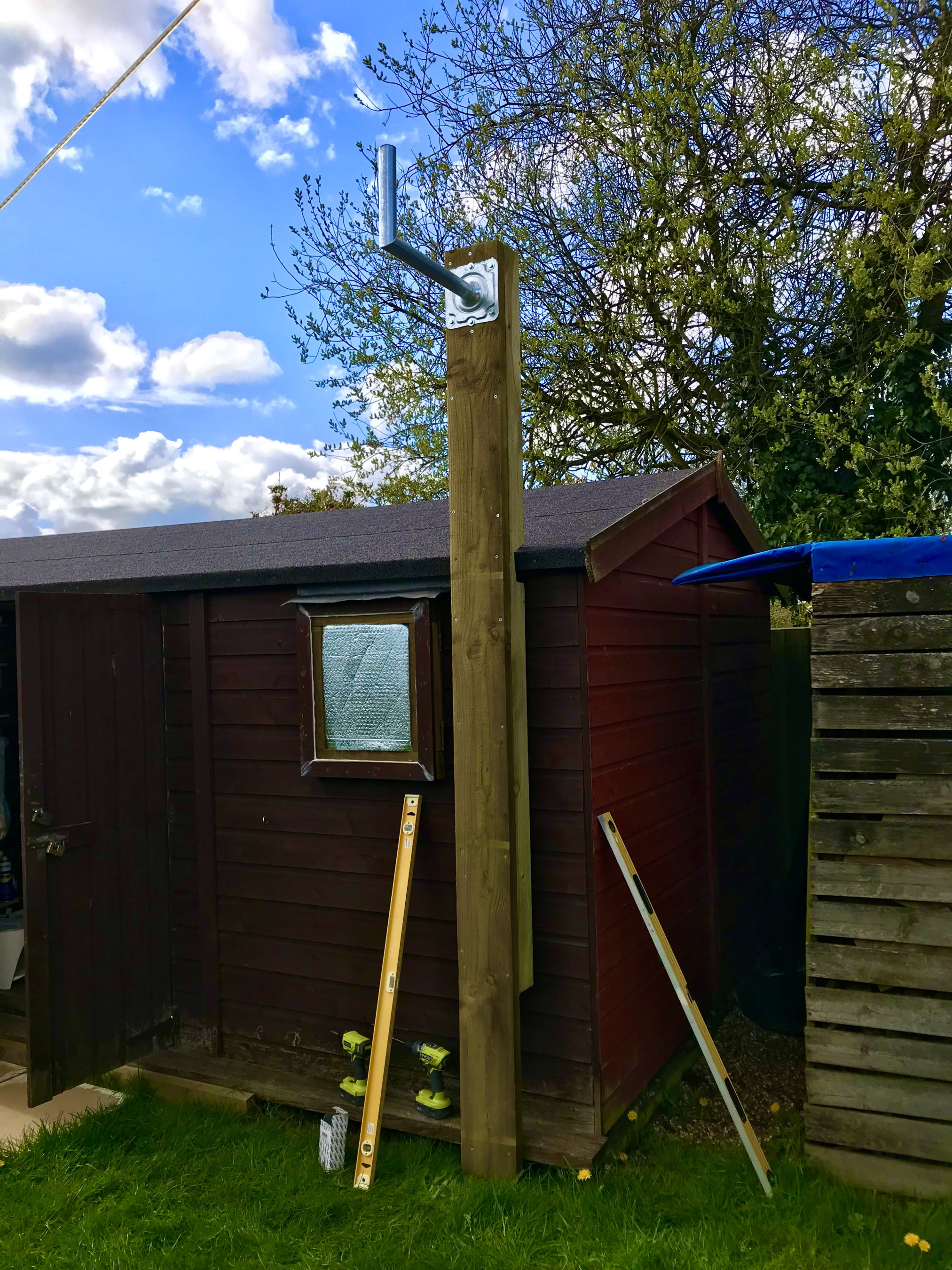
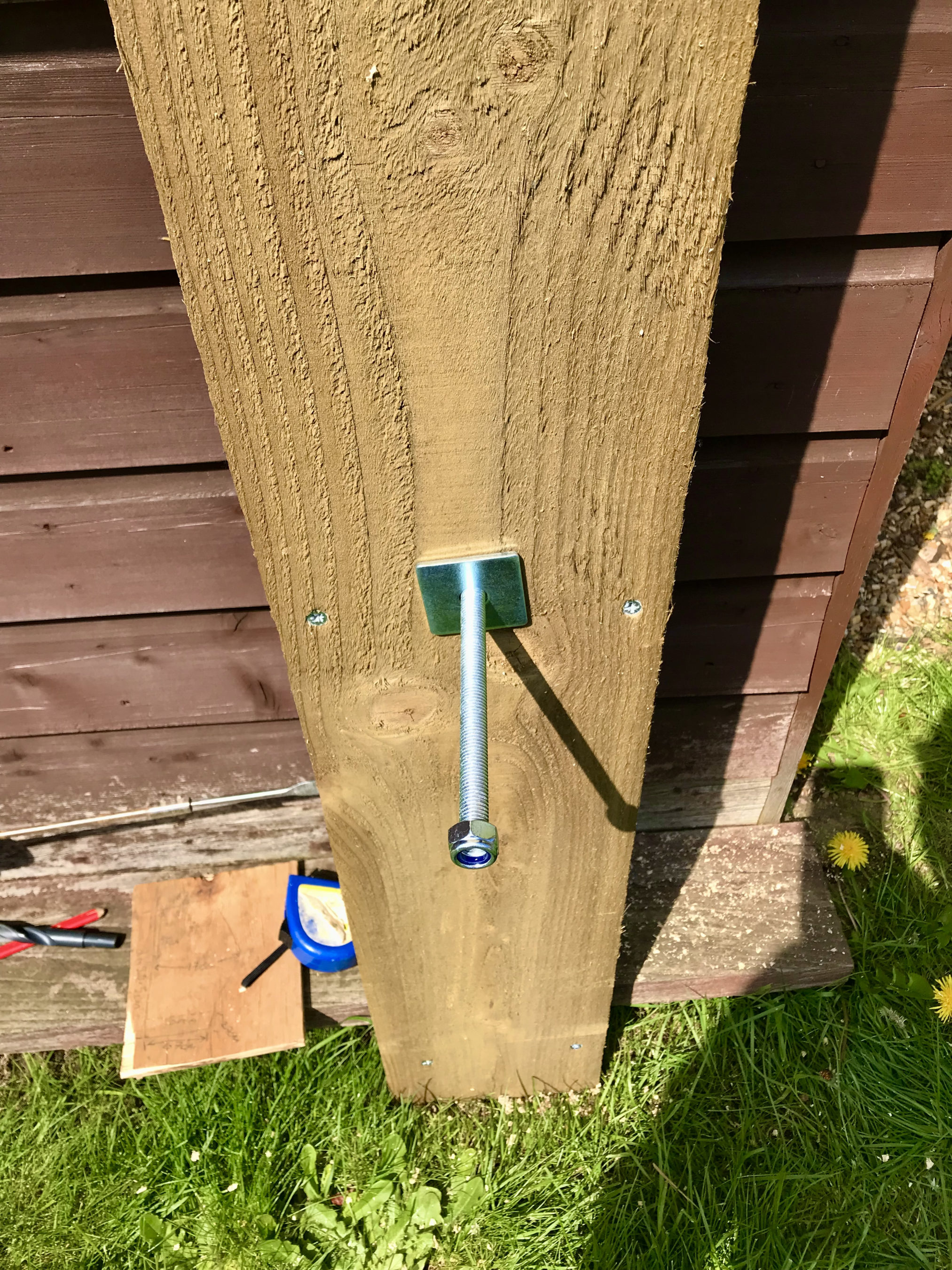
Fortunately we’ve had a mini-summer for the last 2 days and so I started work on getting the dish mount built. Using some timber from the local saw mill I made a braced 3m tall post which I screwed to the side of the cabin to provide a stable fixing platform. I used a couple of threaded bars to bolt through the walls of the cabin to ensure a solid fixing.

Next I mount the metal dish bracket to the top of the wooden post taking the total height up to around 3.2m above ground. This gives plenty of head clearance down below.

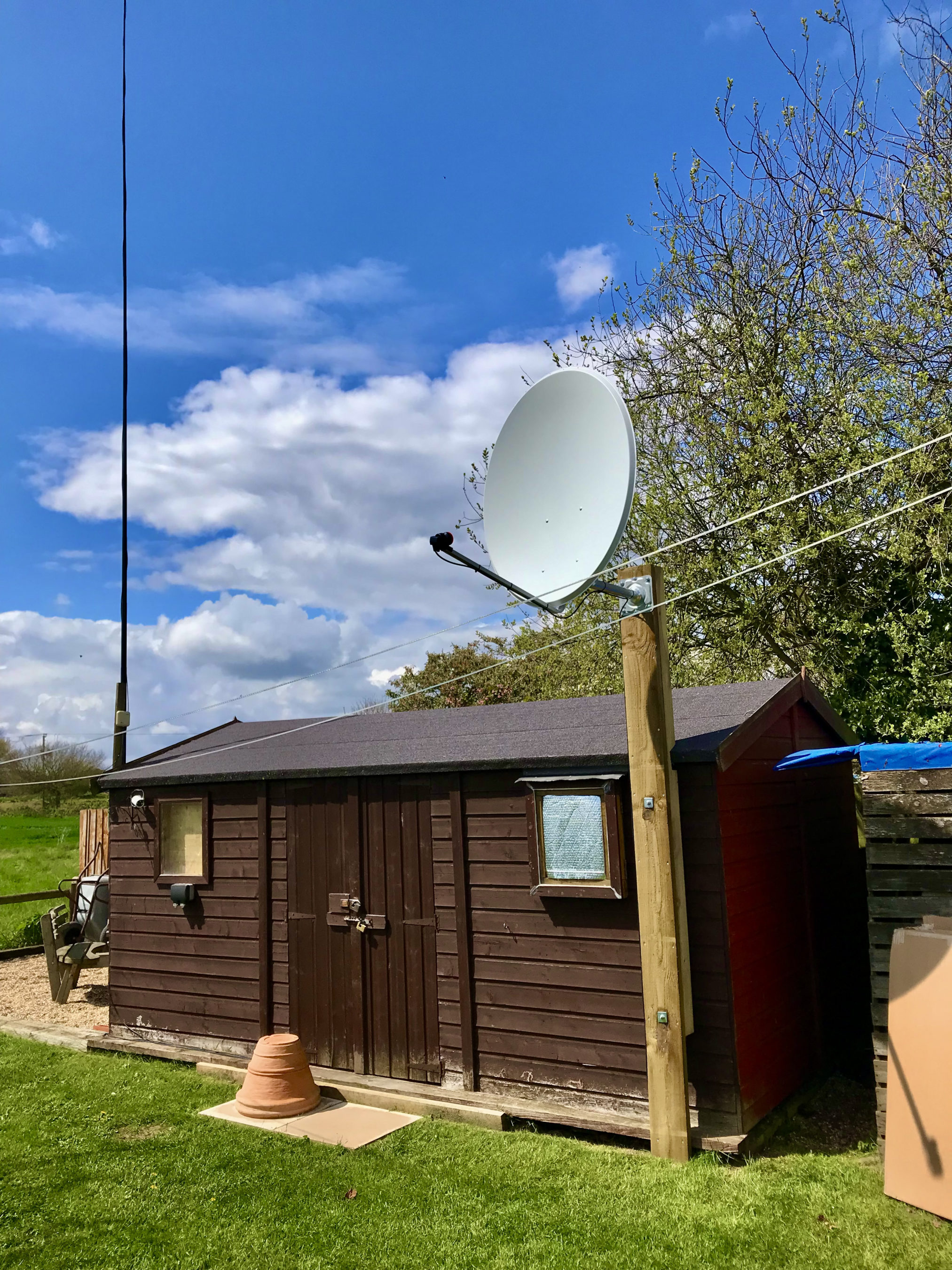
Next I assembled the dish and and attached it to the metal dish bracket at the top of the wooden post.

QO-100 1.1m dish mounted on the 3.2m AGL fixing

Attaching and cabling the Bullseye LNB was an easy job. I used some high quality coax cable that I purchase from the Satellite Superstore when I purchase the dish. I also had to set the LNB skew to -17.8 degrees. The marking on the LNB are tiny and go up in fives and so it’s pretty much impossible to get exactly -17.8 degrees so I turned it to 15 and then a tiny bit. It was as close I could get it!

Next I needed the information on where to point the dish. Fortunately there is a great web app on the BATC website where you can move a pin on a map to your location and all the information you need to align the dish is automagically calculated for you.

Armed with this info I set about aligning the dish. Getting it as close as possible I lightly locked off the dish and continued getting the coax in to the radio room so that I could connect it to my Funcube Dongle Pro+ (FCD) SDR receiver. Since the LNB needs a 12v DC feed I had to put inline a “Bias Tee” unit. This unit allows you to inject 12v onto the coax going up to the LNB but, stops it from coming back into the receiver. I used a Bias Tee that I purchased from Amazon with the Bullseye LNB.

Bias Tee mounted under the station desk

Connecting the coax to my Funcube Dongle Pro+ I was really pleased to see that I was receiving signals from the satellite perfectly well. I decided to take my laptop up onto the roof of the cabin and see if I could improve the reception further. To my amazement with very tiny changes in elevation and azimuth I was able to improve the QO-100 beacon signal by a further 10dB.

Being pleased with the dish alignment I started to tighten it so that it couldn’t move in the wind. Unfortunately this caused the dish to move a tiny amount which reduced the signal strength. I loosened the bolts off again and realigned the dish once more. This time when I tightened the clamps I did it a bit at a time on each bolt working my way round them so that the dish didn’t move. Doing it this way I still lost 1dB off the QO-100 beacon signal due to tiny amounts of movement but, decided I could live with the 1dB reduction.

QO-100 dish successfully mounted & aligned with HF antennas in the background

Below is a very short video clip showing a German station talking on the QO-100 satellite. As you can see the signal is nice and strong and extremely clear. I did find that the output from the LNB was actually too much for the FCD SDR and so I reduced the LNA setting in GQRX to 0dB. This reduced the background noise level considerably as the receiver was no longer being overloaded and made the signals much more prevalent above the noise floor.

Short video clip showing signal clarity from the QO-100 Satellite

I’m really pleased at the performance of the receive path and have now ordered the 2.4Ghz hardware from DXPatrol and Nolle Engineering so that I can build the transmit path.

I have also made some improvements to my QO-100 Node Red Dashboard so that I can work split on the satellite using my IC-705 and FCD SDR.

QO-100 Node Red Dashboard with ‘Split’ capability

Once the 2.4Ghz hardware arrives I’ll update the blog with progress.

More soon …

QO-100 Station – Initial parts purchase

After much reading and viewing of youtube videos I have finally settled on the parts that I want to use to build my QO-100 Satellite ground station.

Initially I’m only going to build the receive path of the QO-100 station. From the articles and blogs I’ve read online all the experienced Amateur Radio satellite Op’s recommend getting the receive side sorted first and then moving onto the transmit path.

I need to stress here that I have no experience of radio above 433Mhz (70cm), a band that I have only used a handful of times. 99% of my Amateur Radio life has been spent below 30Mhz and so this is going to be a very new experience for me.

So, what am I going to purchase for the receive path?

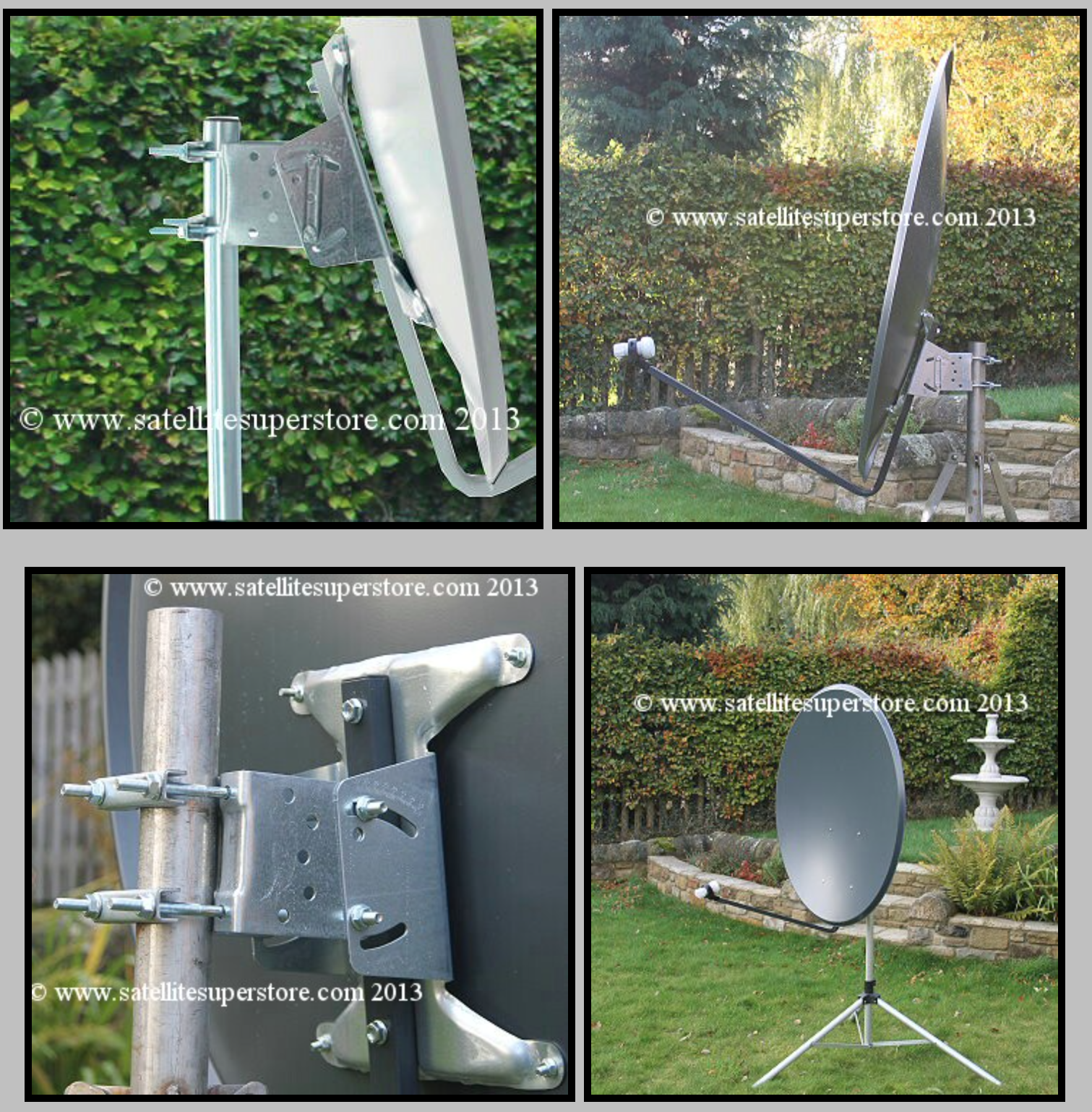
I’ve settled on a 1.1m off-set dish from the Satellite Super Store that should give me plenty of gain if I manage to get it pointed successfully at the bird.

I’ll pair a Bullseye 10Ghz TCXO LNB with the dish to give me a high stability receive path that shouldn’t wander too much up and down the band with temperature changes throughout the seasons.

1.1m Off-Set Dish for QO-100

The Bullseye LNB gets extremely good reviews from the HAM Satellite community, although it is a little on the expensive side compared to many others available. Since I only want to do this once I’ve gone with the more expensive option in the hope that it gives me the stability I’m looking for.

Since we’ve never had satellite TV here at home I’ve only just learnt that LNBs require a voltage feed since reading about other peoples QO-100 station builds. Most LNBs can be used for either horizontal or vertical polarisation and are switched by feeding with either 12v or 18v respectively. The LNBs also use this same voltage feed to do the frequency down conversation and some amplification of the received signal.

At the moment I’m only looking to get onto the narrowband part of the QO-100 satellite service and so I will need to feed the LNB with around 12v to ensure vertical polarisation is achieved. The easiest way to do this is to inject the 12v feed up the coax cable to the LNB.

Bullseye 10Ghz TCXO LNB

To achieve this I will need to purchase a little circuit called a Bias Tee. This relatively simple circuit consists of a capacitor and inductor combination that stops the 12v from going back into the receiver whilst at the same time stopping the RF from going back into the power supply.

Bias Tee units are relatively cheap to buy online and I have decided to get one from Amazon that has been recommended in a number of blogs posts I have read during my research.

Broco Bias Tee

With these parts ordered I now need to source the materials to mount the dish up above head height in the garden with a clear view of the sky in the direction of the satellite.

Getting the dish up high enough to be above head height will be important for when I get the 2.4Ghz uplink path in place. At these frequencies it’s important to ensure that no one is able to walk across the front of the dish whilst I’m transmitting. I’m hoping to get the dish up about 3m in the air in such a fashion that it is rigid enough to stop the dish moving around in the wind. I must admit I’ve not done any wind load calculations for the 1.1m dish so I’ll have to see how it goes over time. Fortunately where I want to put the dish is fairly well sheltered from the north wind that often howls through here so, hopefully it won’t be an issue.

More soon …