Since setting up the new HAM station here in the UK the one band I’ve not yet got back onto is 160m, one of my most favourite bands in the HF spectrum and one that I was addicted to when I live in France (F5VKM).
Having such a small garden here in the UK there is no way I can get any type of guyed vertical for 160m erected and so I needed to come up with some sort of compromise antenna for the band.
Only being interested in the FT4/8 and CW sections of the 160m band I calculated that I could get an inverted-L antenna up that would be reasonably close to resonant. It would require some additional inductance to get the electrical length required and some impedance matching to provide a 50 Ohm impedance to the transceiver.
Measuring the garden I found I could get a 28m horizontal section in place and a 10m vertical section using one of my 10m spiderpoles. This would give me a total of 38m of wire that would get me fairly close to the quarter wave length.
For impedance matching I decided to make a Pi-Network ATU. I’ve made these in the past and found them to be excellent at matching a very wide range of impedances to 50 Ohm.
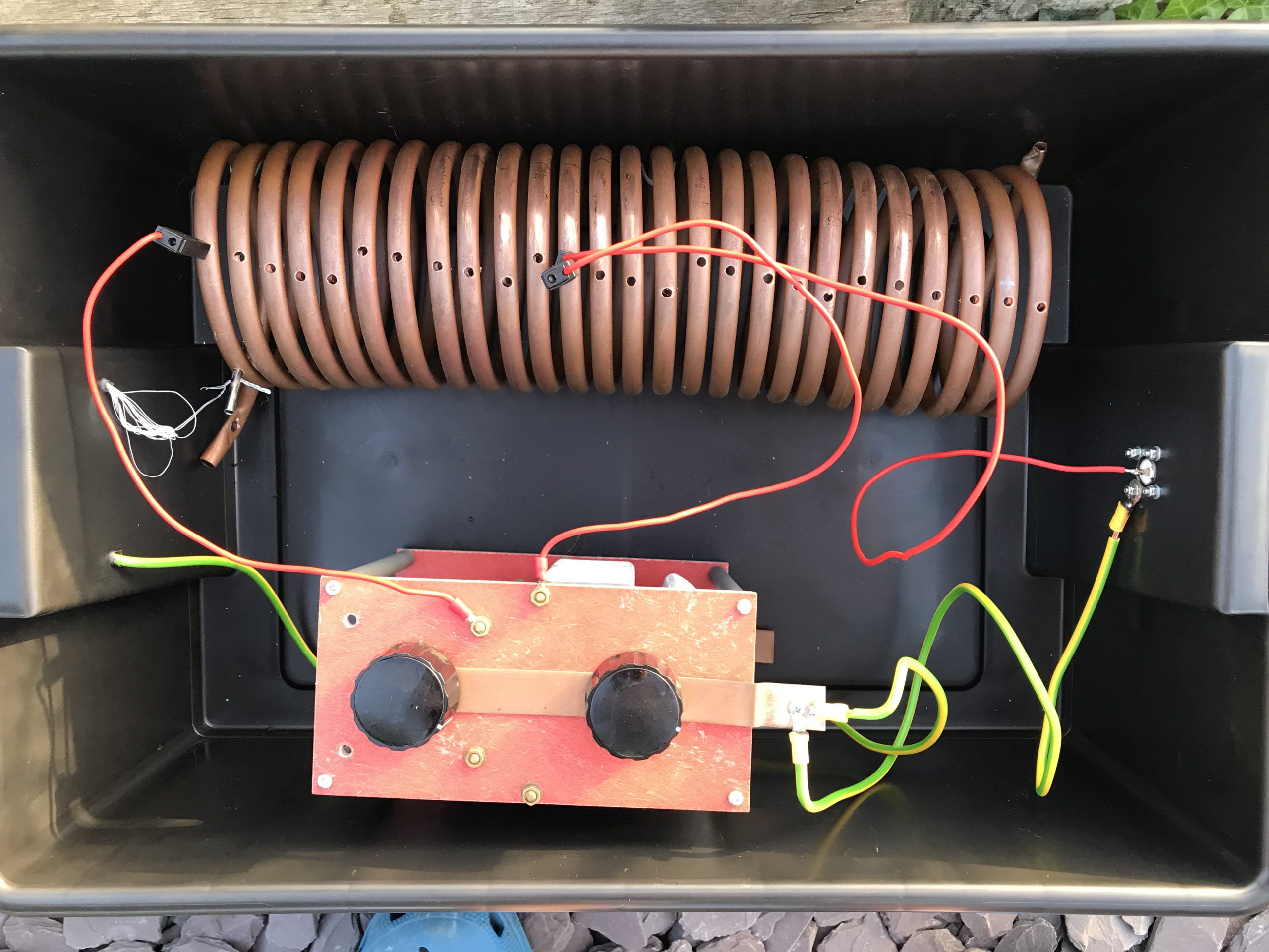
M0AWS Homebrew Pi-Network ATU
Since I still had the components of the Pi-Network ATU that I built when I lived in France I decided to reuse them as it saved a lot of work. The inductor was made from some copper tubing I had left over after doing all the plumbing in the house in France and so it got repurposed and formed into a very large inductor. The 2 x capacitors I also built many years ago and fortunately I’d kept locked away as they are very expensive to purchase today and a lot of work to make.
Getting the Inverted-L antenna up was easy enough and I soon had it connected to the Pi-Network ATU. I ran a few radials out around the garden to give it something to tune against and wound a 1:1 choke balun at the end of the coax run to stop any common mode currents that may have appeared on the coax braid.
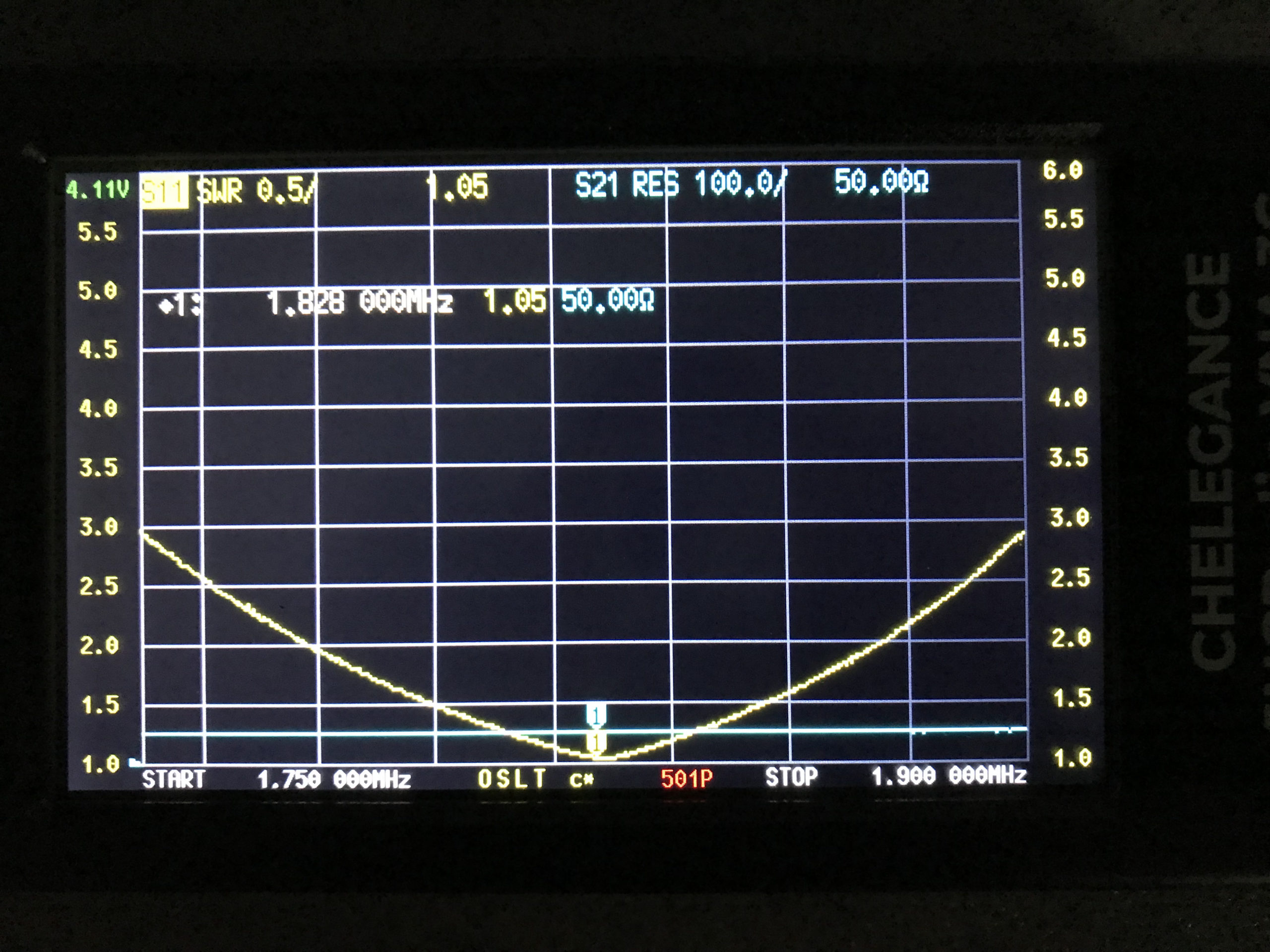
Connecting my JNCRadio VNA I found that the Inverted-L was naturally resonant at 2.53Mhz, not too far off the 1.84Mhz that I needed. Adding a little extra inductance and capacitance via the ATU I soon had the antenna resonant where I wanted it at the bottom of the 160m band.
M0AWS 160m Inverted L Antenna SWR Curve
With the SWR being <1.5:1 across the CW and FT8 section of the band I was ready to get on 160m for the first time in a long.
Since it’s still summer in the UK I wasn’t expecting to find the band in very good shape but, was pleasantly surprised. Switching the radio on before full sunset I was hearing stations all around Europe with ease. In no time at all I was working stations and getting good reports using just 22w of FT8. FT8 is such a good mode for testing new antennas.
As the sky got darker the distance achieved got greater and over time I was able to work into Russia with the longest distance recorded being 2445 Miles, R9LE in Tyumen Asiatic Russia.
In no time at all I’d worked 32 stations taking my total 160m QSOs from 16 to 48. I can’t wait for the long, dark winter nights to see how well this antenna really performs.
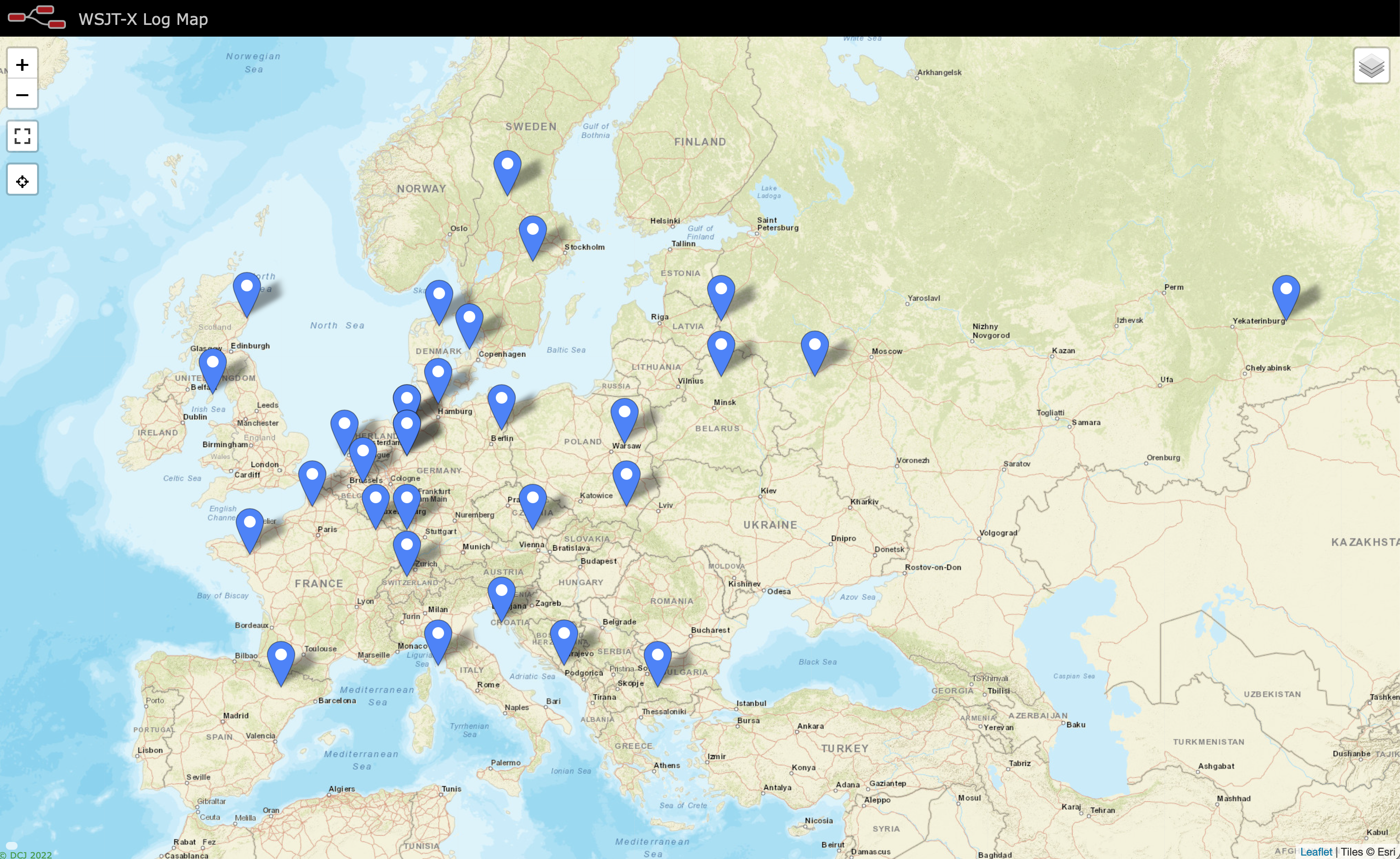
M0AWS Map showing stations worked on 160m using Inverted L Antenna
The map above shows the locations of the stations worked on the first evening using the 160m Inverted-L antenna. As the year moves on and we slowly progress into winter it will be fun to start chasing the DX again on the 160m band..
UPDATE 6th October 2023. Been using the antenna for some time now with over 100 contacts on 160m. Best 160m DX so far is RV0AR in Sosnovoborsk Asiatic Russia, 3453 Miles using just 22w. Pretty impressive for such a low antenna on Top Band.
I’ve been gradually building my QO-100 ground station over the last few months and have had the receive path working for some time now. One of the things I really miss with the Funcube Dongle Pro+ (FCD) SDR is a real VFO knob for changing frequency.
My QO-100 Node Red dashboard is configured so that I can have the FCD track the uplink frequency from the IC-705 but, sometimes I use the FCD without the IC-705 in the shack and so a physical VFO would be handy.
Many years ago when I lived in France (F5VKM) I had a Flexradio Flex-3000 SDR, a great radio in it’s time and one that gave me many hours of enjoyment. One addition I bought for that station was a Griffin Technology Powermate VFO knob. It worked extremely well with the PowerSDR software for the Flex-3000 and I used it for many years.
Many years later I’m back in the UK and much of my equipment is packed away in the attic, including the Griffin Technology Powermate VFO.
I decided to dig it out and see if I could get it working with GQRX SDR software. Sadly I couldn’t get it working with GQRX however, I did find a way of getting it working with Node Red and thus could add it to my QO-100 Node Red Dashboard and then control GQRX with it via a simple Node Red flow.
Griffin Technology Powermate VFO
Plugging the Powermate VFO into my Kubuntu PC it wasn’t immediately recognised by the Linux O/S. After a little searching I found the driver on Github. I added the PPA to my aptitude sources and installed the driver using apt.
Once installed the default config for the Powermate device is to control the default audio device volume. To make the device available for use as a VFO knob you need to change the configuration so that the default setting is disabled. To do this is relatively easy, just edit the config file using your favourite command line editor (Vi/Vim in my case) and add the following entry.
vi /etc/powermate.toml

# Entry to control HDMI volume with Powermate
#sink_name = "alsa_output.pci-0000_01_00.1.hdmi-stereo"

# Set powermate not to work with volume control
sink_name = ""
As shown above, comment out the default “sink_name” entry (Yours may be different depending on audio device in your PC) and add in the Powermate “sink_name” entry that effectively assigns it to nothing.
Once this is done, save the file and exit your editor and then reboot the PC.
Next you’ll need to install a small program called evtest.
sudo apt install evtest
To check the evtest program has installed correctly, plugin your Powermate VFO to any available USB port and run the following command in a terminal.
evtest /dev/input/powermate
Turning the Powermate knob you should see output on the screen showing the input from the device. You should also see BTN events for each press of the Powermate device.
Input driver version is 1.0.1
Input device ID: bus 0x3 vendor 0x77d product 0x410 version 0x400
Input device name: "Griffin PowerMate"
Supported events:
  Event type 0 (EV_SYN)
  Event type 1 (EV_KEY)
    Event code 256 (BTN_0)
  Event type 2 (EV_REL)
    Event code 7 (REL_DIAL)
  Event type 4 (EV_MSC)
    Event code 1 (MSC_PULSELED)
Properties:
Testing ... (interrupt to exit)
Event: time 1685816662.086666, type 2 (EV_REL), code 7 (REL_DIAL), value -1
Event: time 1685816662.086666, -------------- SYN_REPORT ------------
Event: time 1685816662.318638, type 2 (EV_REL), code 7 (REL_DIAL), value -1
Event: time 1685816662.318638, -------------- SYN_REPORT ------------
Event: time 1685816662.574615, type 2 (EV_REL), code 7 (REL_DIAL), value -1
Event: time 1685816662.574615, -------------- SYN_REPORT ------------
Event: time 1685816663.670461, type 2 (EV_REL), code 7 (REL_DIAL), value 1
Event: time 1685816663.670461, -------------- SYN_REPORT ------------
Event: time 1685816664.030421, type 2 (EV_REL), code 7 (REL_DIAL), value 1
Event: time 1685816664.030421, -------------- SYN_REPORT ------------
Event: time 1685816664.334389, type 2 (EV_REL), code 7 (REL_DIAL), value 1
Event: time 1685816664.334389, -------------- SYN_REPORT ------------
Event: time 1685816665.334255, type 1 (EV_KEY), code 256 (BTN_0), value 1
Event: time 1685816665.334255, -------------- SYN_REPORT ------------
Event: time 1685816665.558230, type 1 (EV_KEY), code 256 (BTN_0), value 0
Event: time 1685816665.558230, -------------- SYN_REPORT ------------
Event: time 1685816666.030161, type 1 (EV_KEY), code 256 (BTN_0), value 1
Event: time 1685816666.030161, -------------- SYN_REPORT ------------
Event: time 1685816666.182151, type 1 (EV_KEY), code 256 (BTN_0), value 0
Event: time 1685816666.182151, -------------- SYN_REPORT ------------
At this point you’re ready to stop evtest (CTRL-C) and then create the following little BASH shell script that Node Red will run to collect the O/P from the Powermate USB device.
#!/bin/bash

###############################################
# Griffin Technology Powermate control script #
# for Node Red.                               #
#                                             #
# 04/06/23 - M0AWS - v0.1                     #
#                                             #
###############################################

VAL="1"
echo "STEP-1Hz"

/usr/bin/evtest /dev/input/powermate | while read LINE
do
   case $LINE in

      *"(REL_DIAL), value 1") echo "$VAL"
           ;;

      *"(REL_DIAL), value -1") echo "-$VAL"
           ;;

      *"(BTN_0), value 1") case $VAL in

                              "1") VAL="10"
                                   echo "STEP-10Hz"
                                      ;;

                             "10") VAL="100"
                                   echo "STEP-100Hz"
                                      ;;

                             "100") VAL="1000"
                                    echo "STEP-1Khz"
                                       ;;

                             "1000") VAL="10000"
                                     echo "STEP-10Khz"
                                         ;;

                             "10000") VAL="1"
                                       echo "STEP-1Hz"
                                          ;;
                              esac
                                 ;;
        esac
done
Once the BASH script is copied and pasted into a file called powermate.sh you need to make it executable by using the following command.
chmod 700 ./powermate.sh
If you now run the shell script in a terminal you’ll see a similar output to that shown below from the device when used.
As you can see above the shell script outputs a positive or negative number for VFO tuning and changes the VFO step size each time the Powermate is depressed.
Getting this output from the BASH shell script into Node Red is really simple to achieve using just 3 or 4 nodes.
In the Node Red development UI create the following nodes.
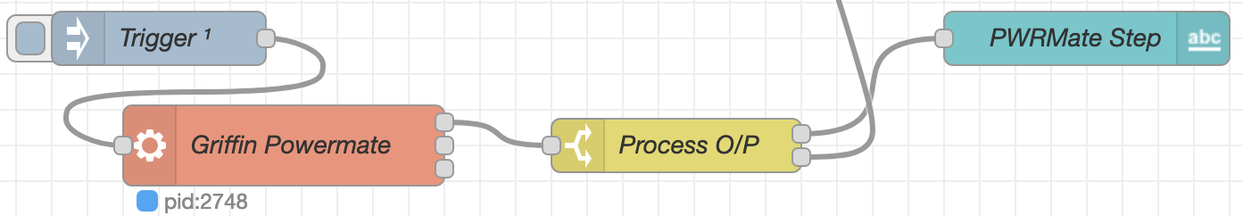
Griffin Powermate Node Red Nodes
The first node in the flow is a simple inject node, here I called it trigger. This sends a timestamp into the next node in the flow at startup to set the flow running.
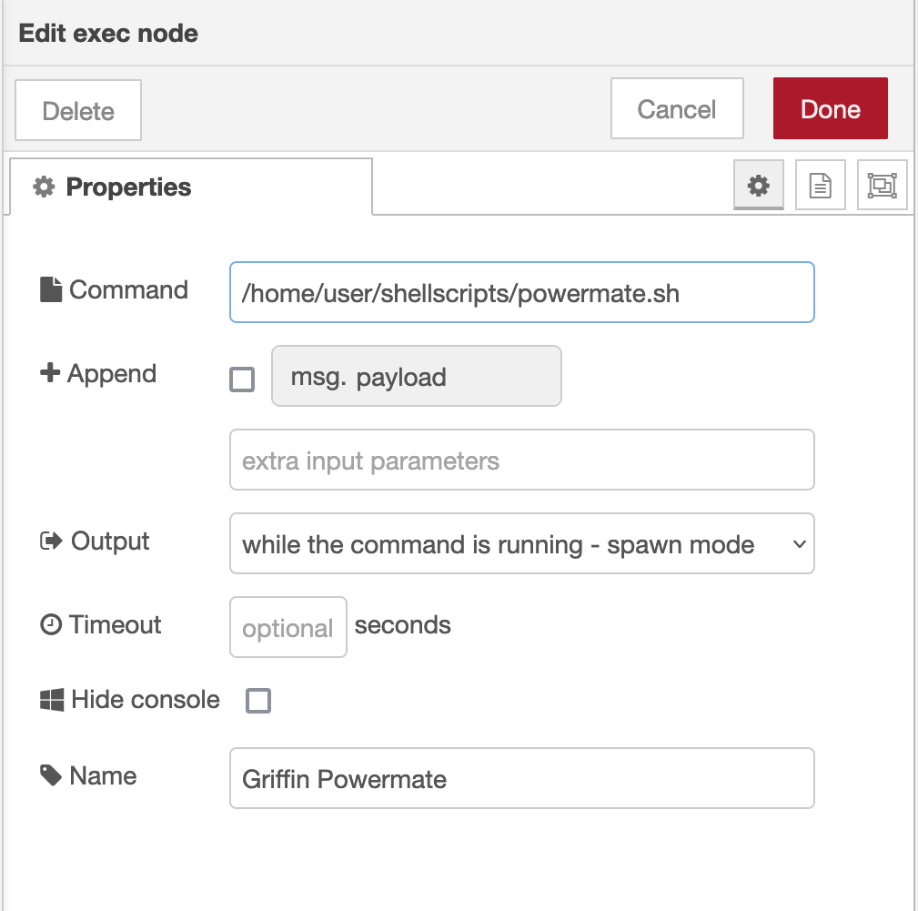
The Griffin Powermate node is a simple exec node that runs the script we created above.
M0AWS Powermate exec node
Configure the node as shown above and connect it to the inject node that’s used as a trigger. Note: Change “user” in the Command field shown above to that of your username on your Linux PC)
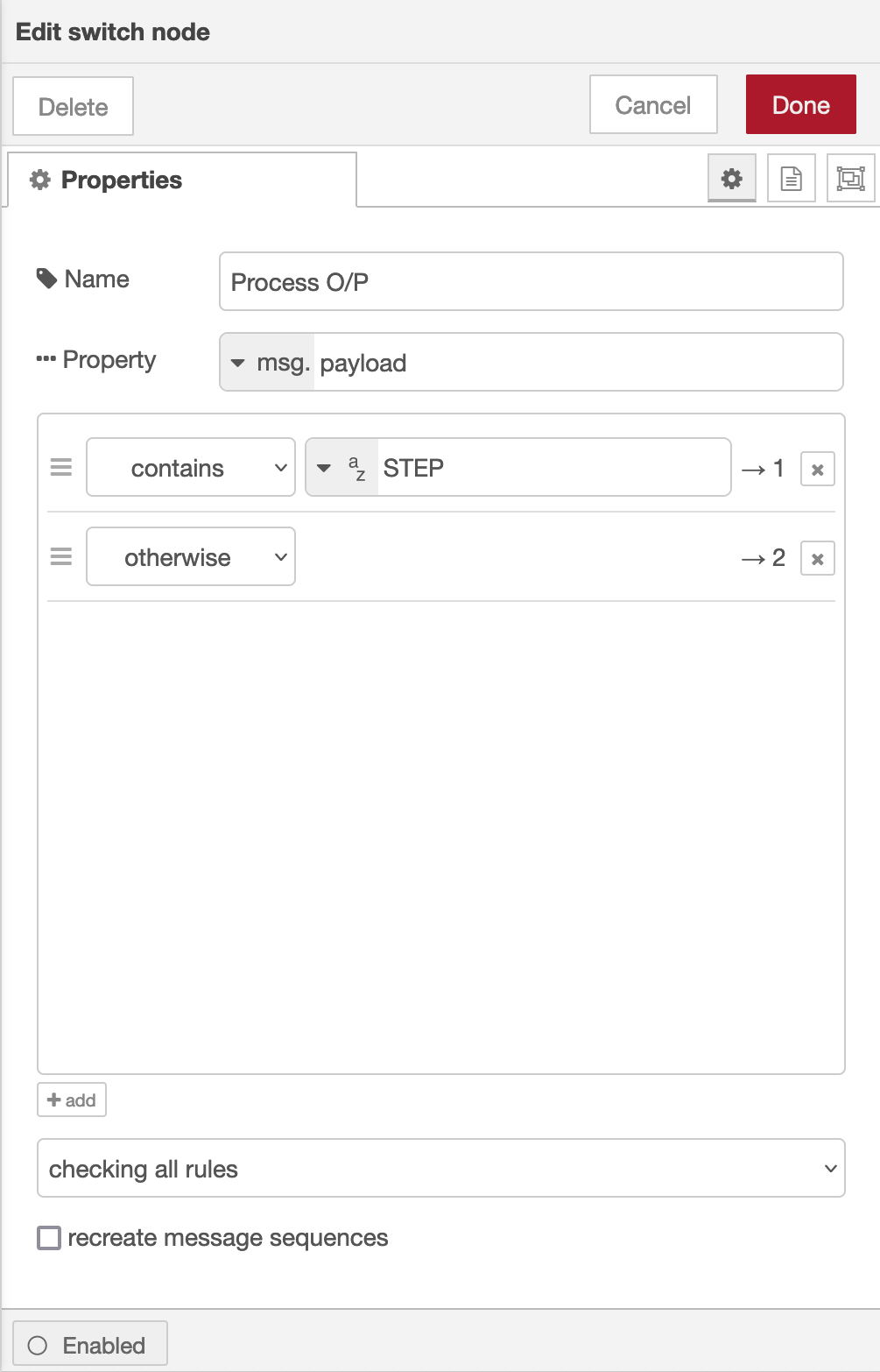
Once done create the third node in the flow, a simple switch node and configure as shown below.
Switch Node for Powermate
The switch node has two outputs, the top one is a text output that is fed into a text field to show the current step size of the Powermate device and the lower output is the numeric output that must be fed into your VFO control flow so that the VFO value is incremented/decremented by the amount output by the Powermate device.
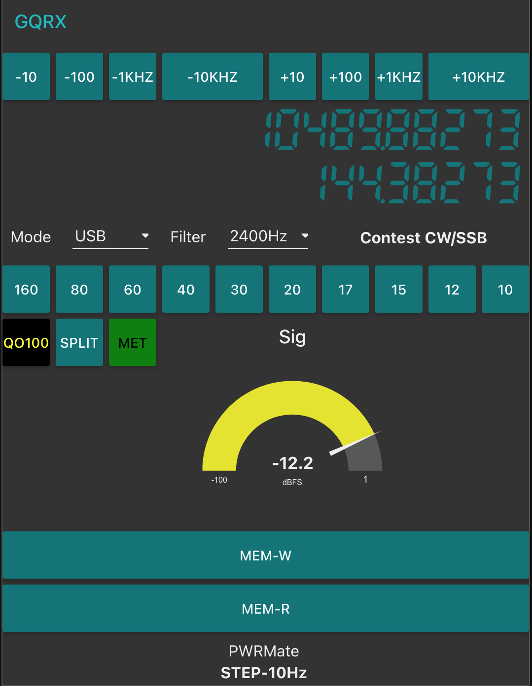
I’ve found the Griffin Technology Powermate USB device works extremely well with Node Red and GQRX that I use for controlling the FCD SDR radio and it’s now part of my QO-100 ground station build.
M0AWS QO-100 Dashboard with Powermate Step Display at bottom
As shown above you can see the Powermate Step size at the bottom of the dashboard, this text changes each time the Powermate device is depressed and will set a step size of 1Hz, 10Hz, 100Hz, 1Khz, 10Khz in a round-robin fashion.
The next stage of the build is the 2.4Ghz transmit path. I now have all the necessary hardware and so this part of the build can finally commence.
More soon …
We use cookies to ensure that we give you the best experience on our website. If you continue to use this site we will assume that you are happy with it.Ok