868Mhz Ground Plane Vertical Antenna

In my quest to improve my Meshtastic signal range using home-brew antennas I’ve finally put together a neat little ground plane vertical antenna for the 868Mhz ISM band.

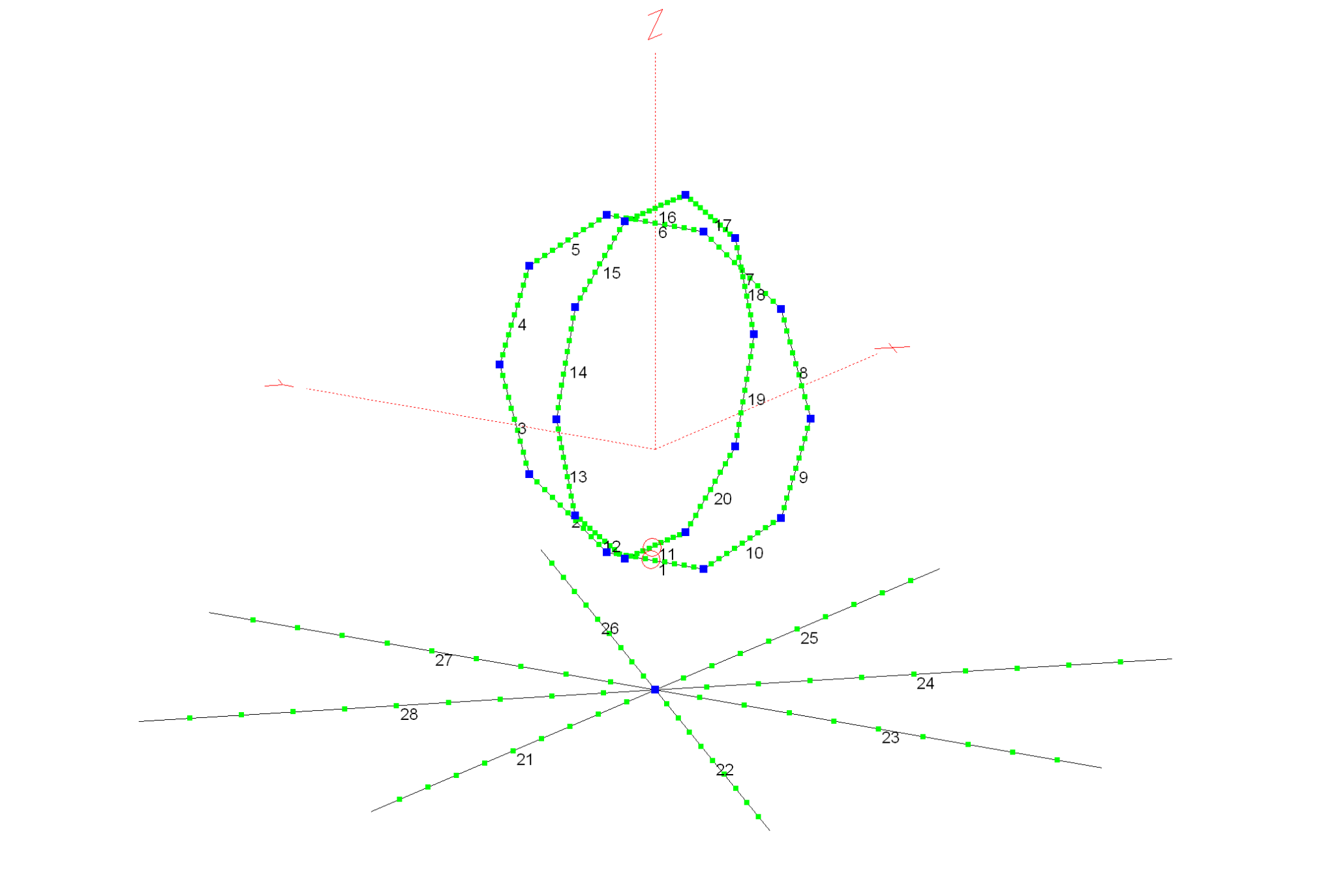
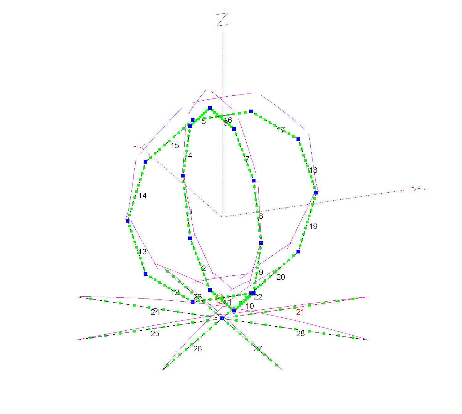
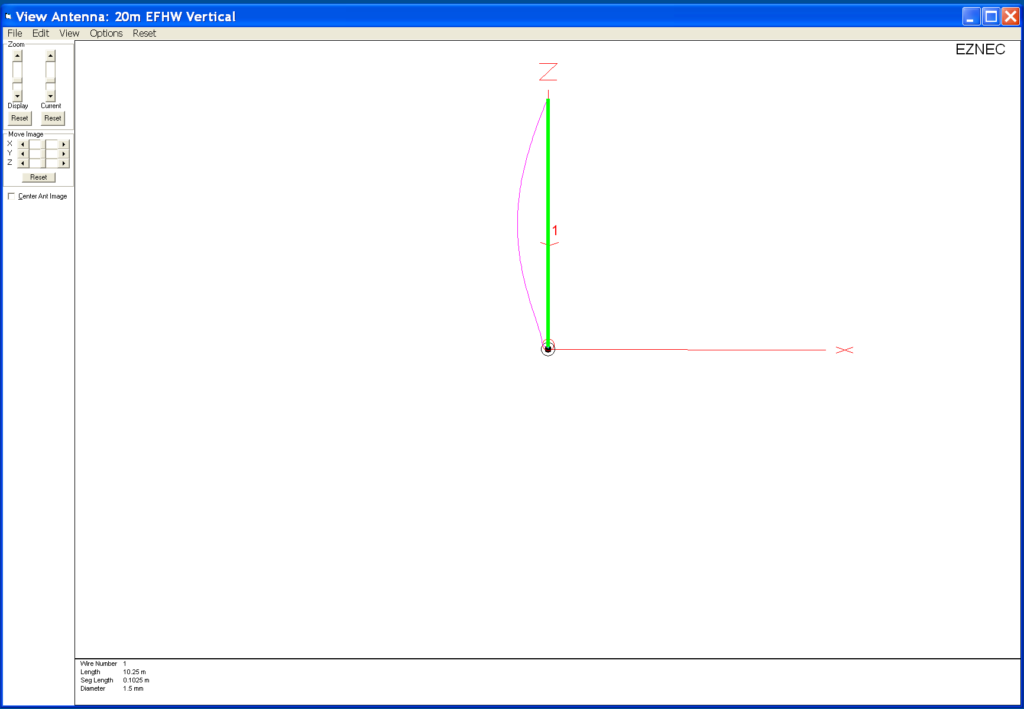
The design follows the normal ground plane simplicity using 4 radials and a vertical radiating element albeit on a tiny scale. The radiating element is 82mm long and the radials are each 92mm long.

M0AWS 868Mhz Ground Plane Vertical Antenna

Initially I modelled the antenna at a height of 3m above the ground with the radials tilted downwards at 45 degrees. I took this approach as this is how I have built ground plane verticals for the 70cm band in the past and so I thought I’d try the same approach on the 868Mhz ISM band. (I later found this to be detrimental to tuning!)

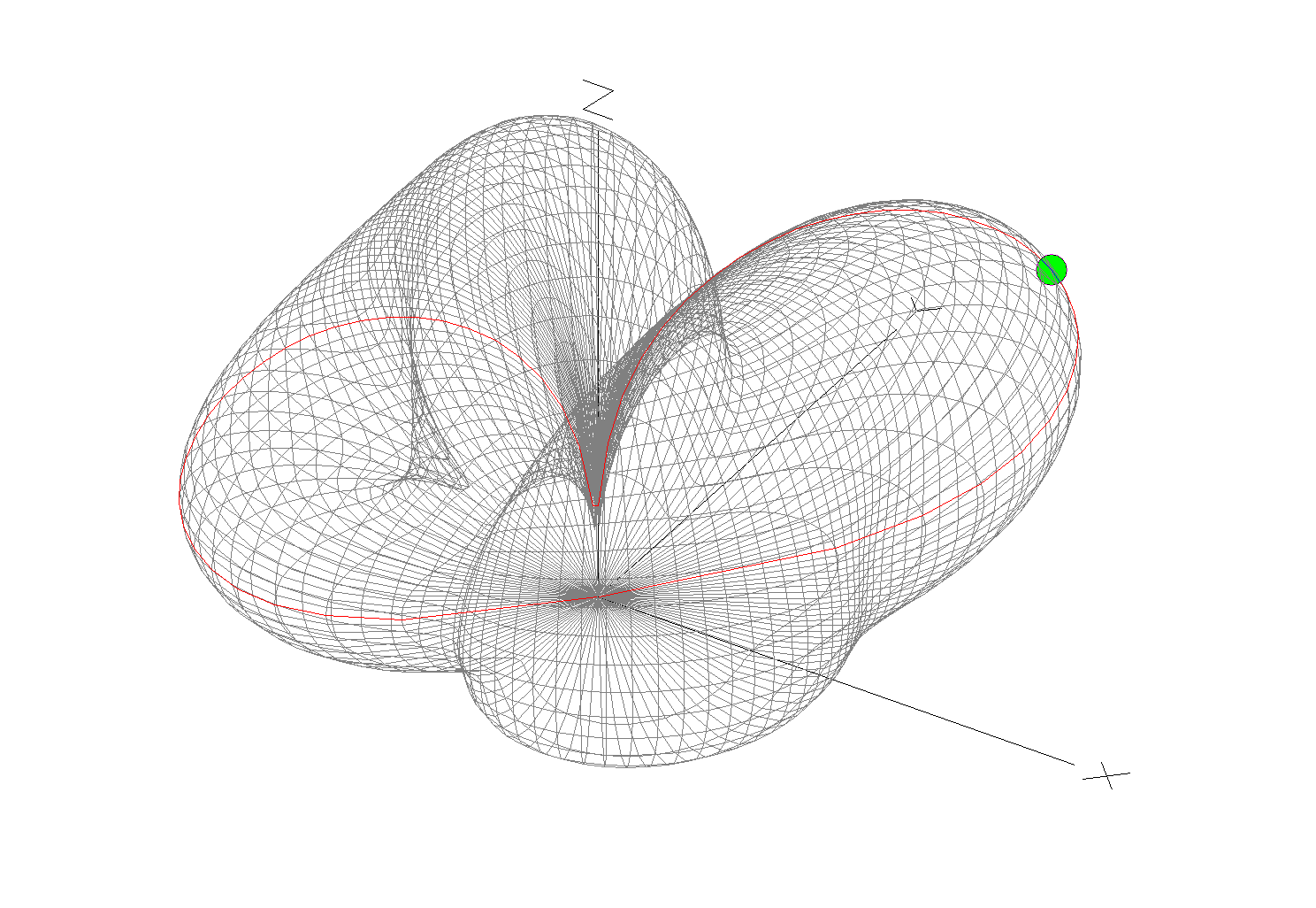
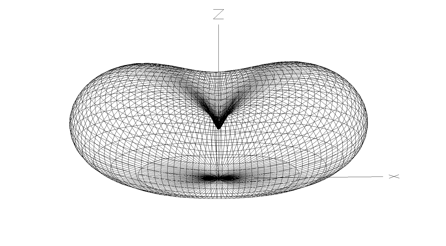
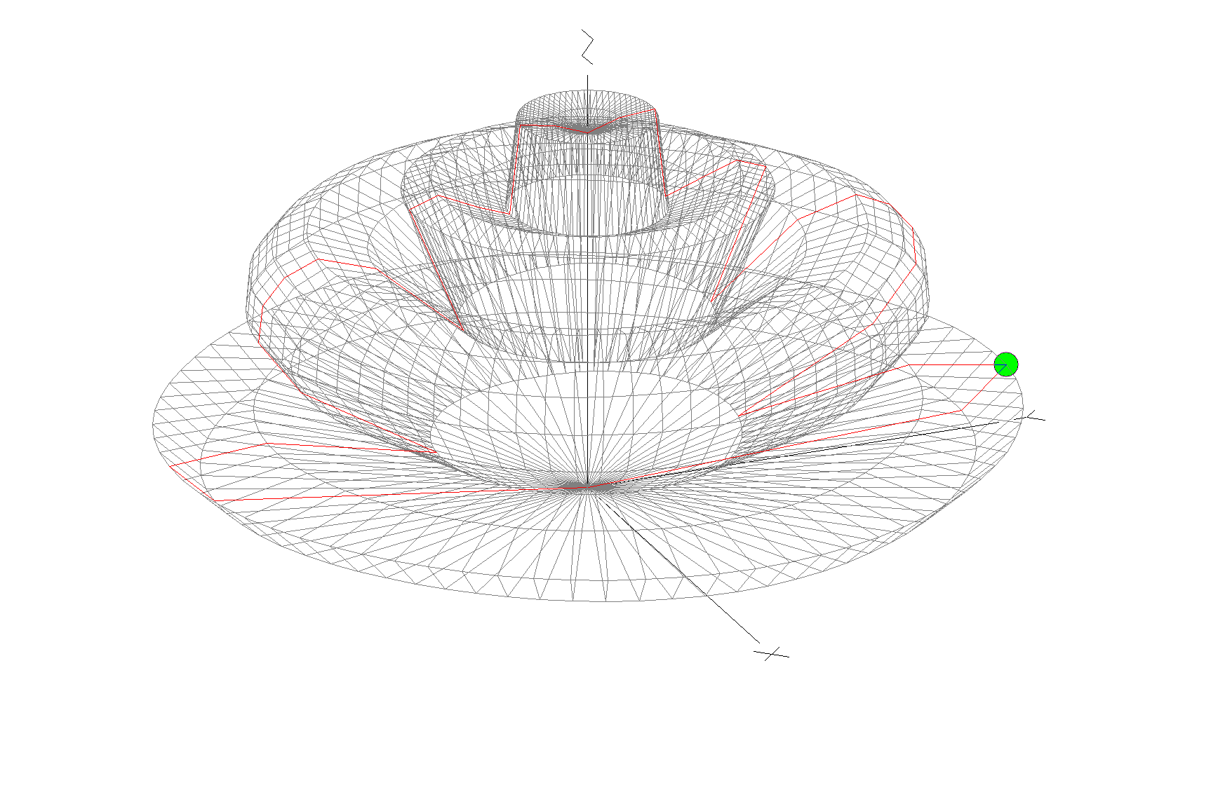
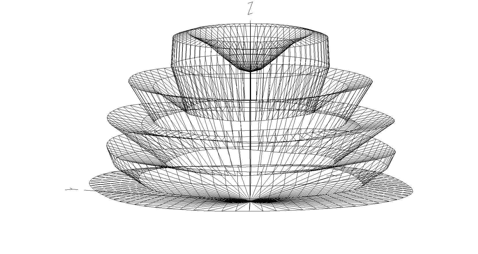
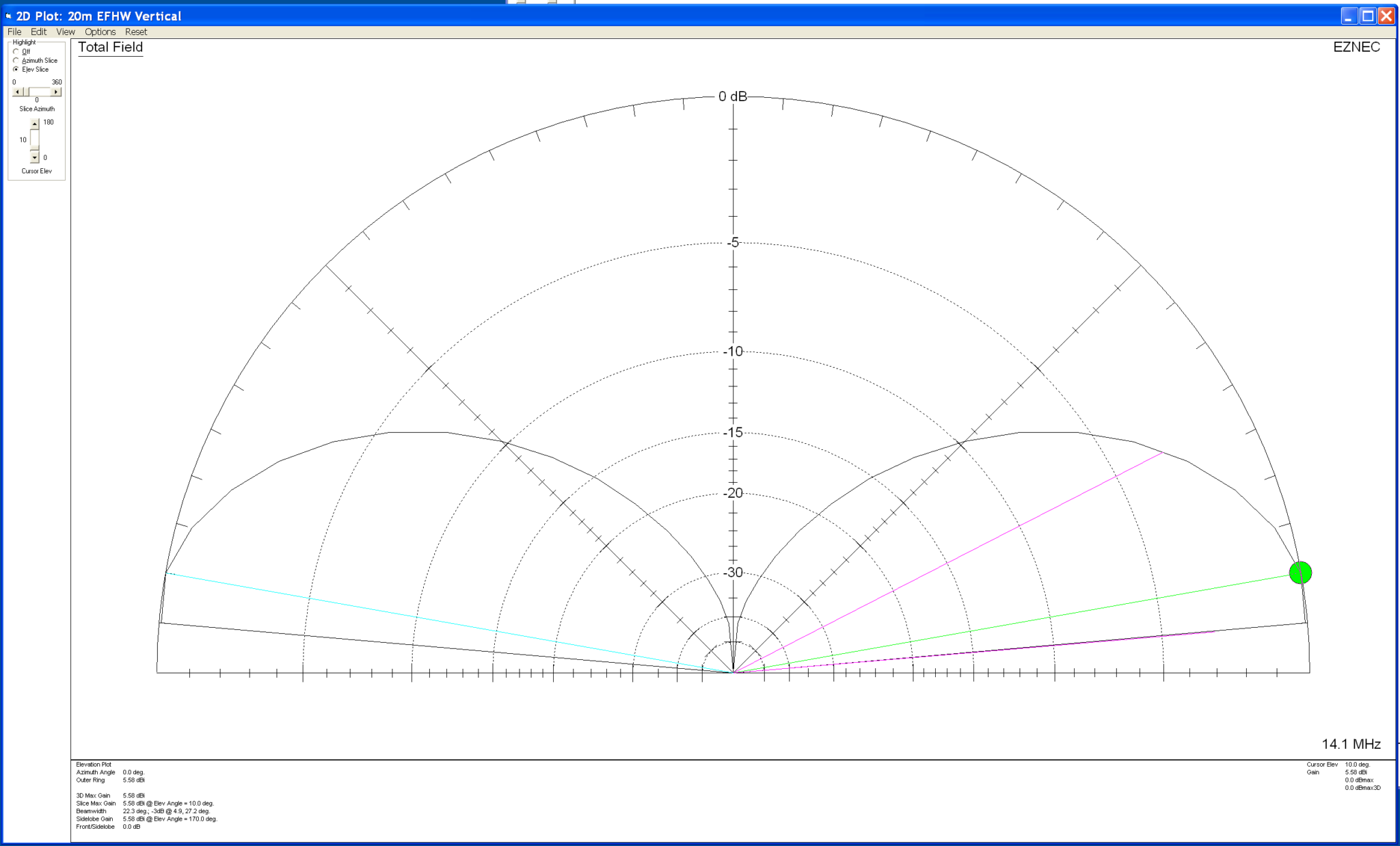
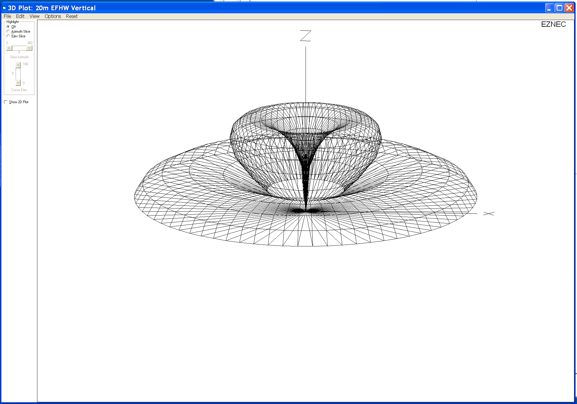
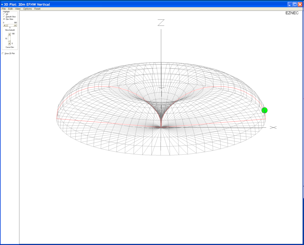
The 3D far field plot for the antenna shows it has a very nice, relatively high gain lobe at just 2 degrees elevation with a number of lower gain lobes higher up.

M0AWS 868Mhz Ground Plane Vertical Antenna 3D Far Field Plot

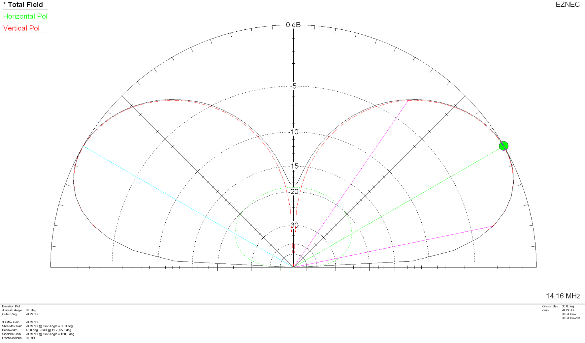
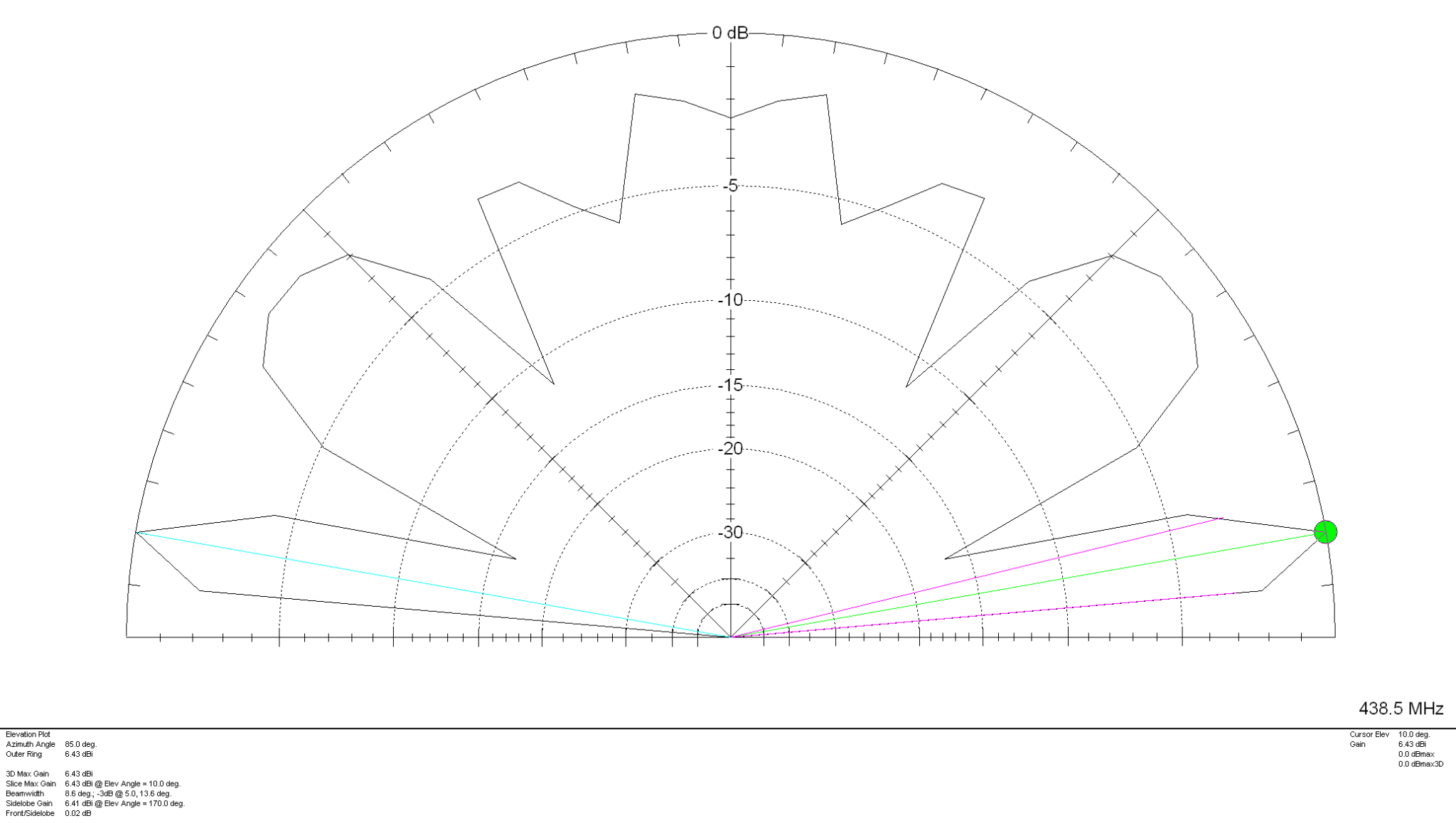
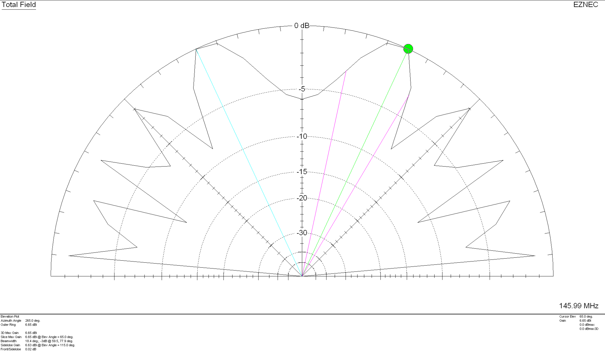
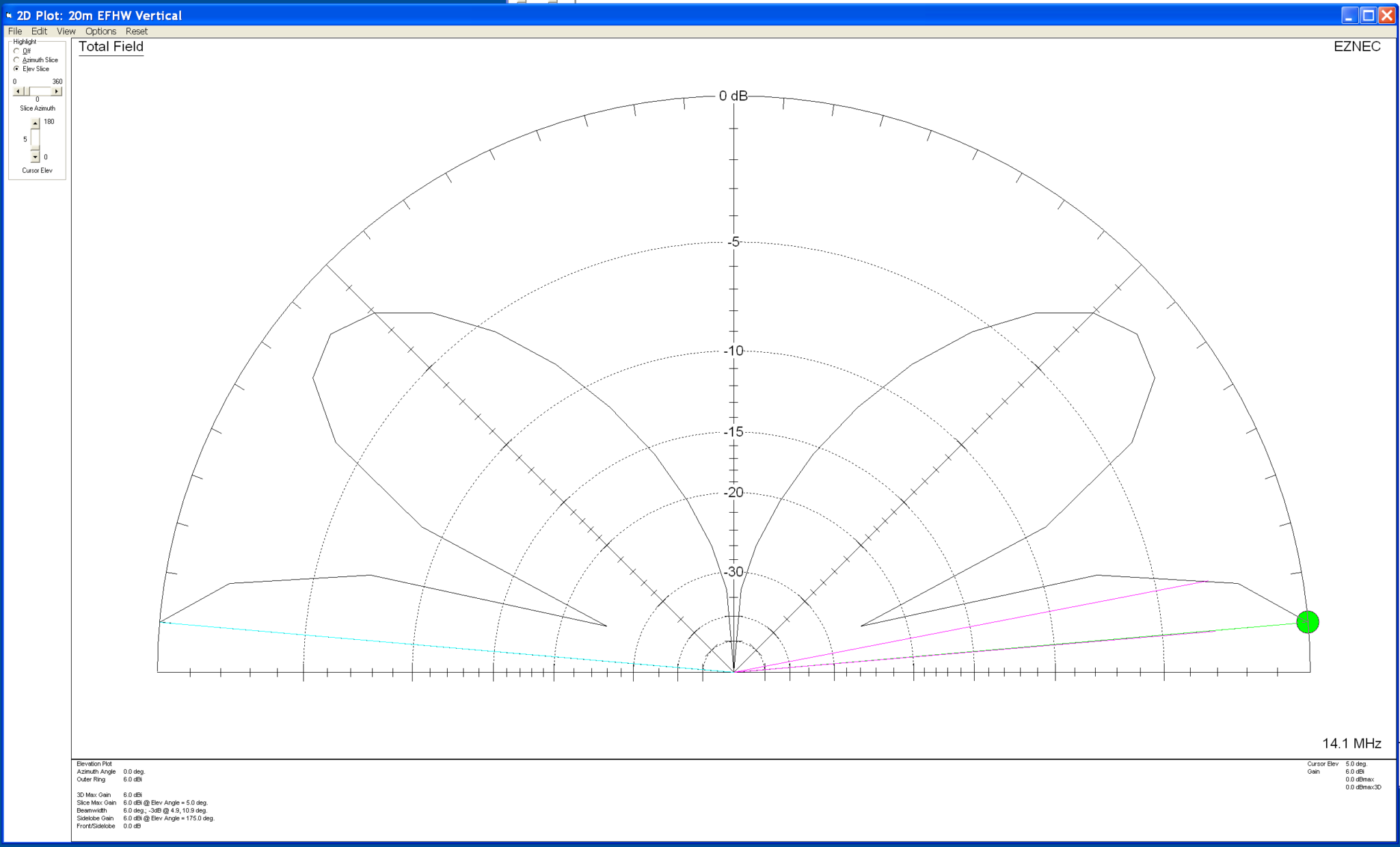
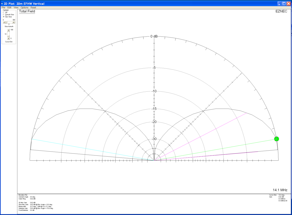
Looking at the 2D far field plot you can get a better understanding of the radiation pattern and gain figures at various angles. At 2 degrees there is 6.7dBi gain with the next major lobe being at 8 degrees with 4.36dBi gain, far more than I imagined I’d see for such a simple antenna.

M0AWS 868Mhz Ground Plane Vertical Antenna 2D Far Field Plot

Putting the antenna together was easy enough with particular attention being paid to the measurements of both the radials and radiating element. I soldered some lugs to the ends of the 2.5mm diameter solid core wire radials to enable easy attachment to the N Type chassis socket that I decided to use as the base for the antenna. This worked out well and provided a good solid mechanical and electrical connection for the 4 radials.

For the radiating element I used an N Type plug with the vertical 2.5mm solid core wire element soldered to the inner centre pin of the male connector. I also slid a small piece of insulation down the wire to stop it from shorting against the metal outer of the plug and then pushed in a tight rubber plug to stop water ingress.

M0AWS 868Mhz Ground Plane Antenna Close Up

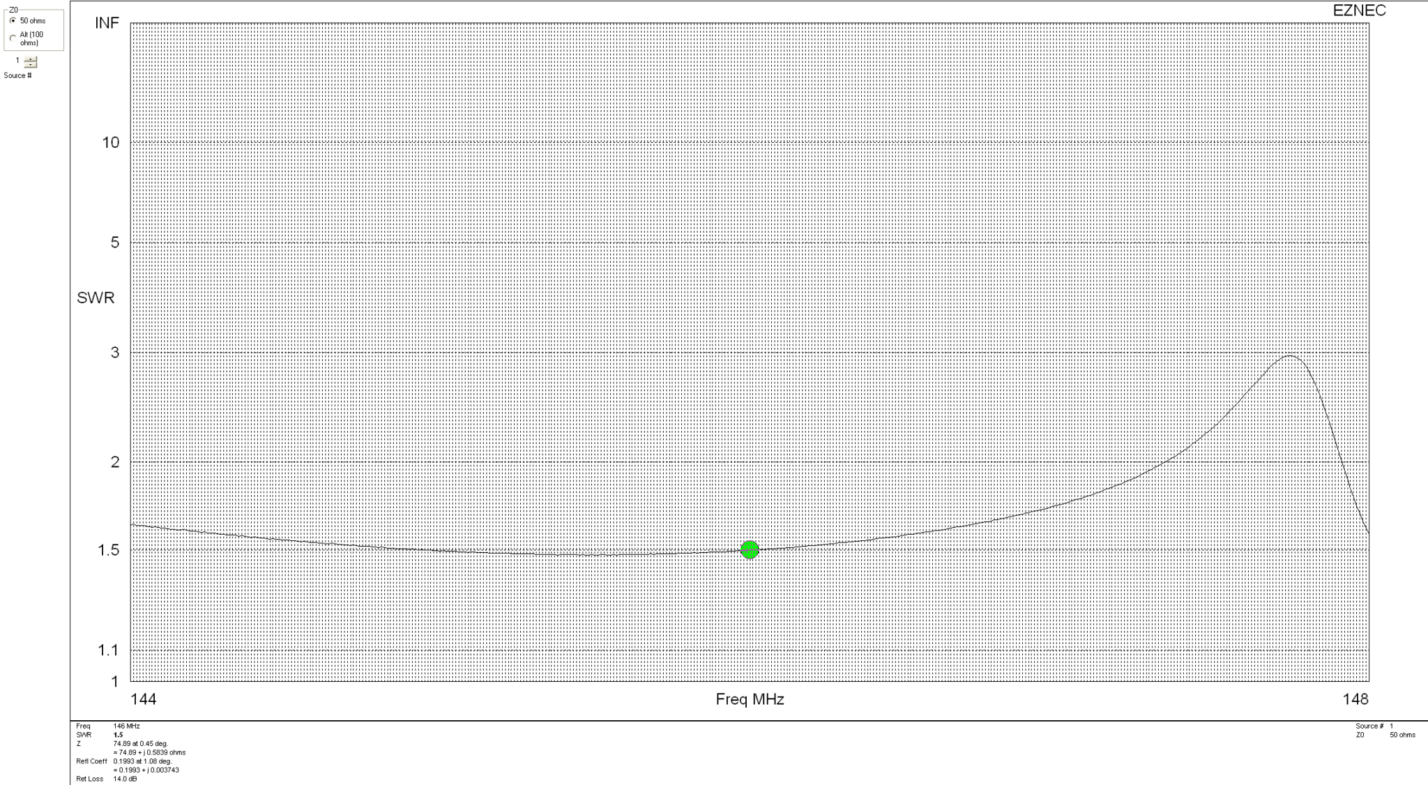
Connecting my VNA I found the antenna was mostly resonant at 790Mhz with an SWR of 2.5:1. I knew this would be the case and that the wires would need a little trimming.

Trimming the wires a couple of times in 1mm nibbles I got the point of resonance up to 868Mhz but, the antenna was still exhibiting a lot of reactance that was keeping the SWR above 2:1. Trimming the radials reduced this slightly but, I could not get an SWR much lower than 1.95:1.

Scratching my head I decided to try moving the radials back up so that they were horizontal rather than at 45 degrees downwards, this had the immediate effect of the SWR dropping to 1.1:1.

M0AWS A rather fuzzy photo of the 868Mhz SWR curve for the GP Antenna

The SWR stays below 1.2:1 from 868Mhz to 871Mhz which is plenty wide enough for the Meshtastic devices. Why there is so much reactance when the radials are bent down at 45 degrees I am not sure, but it was easy enough to resolve.

M0AWS 868Mhz Ground Plane Antenna

The finished antenna is tiny but, seems to work well. Signals from my other nodes are up by 6-9dB according to the SNR reports in the Meshtastic app. I now need to make a couple more of these for my other nodes and then hope to hear some other nodes locally once they appear on air.

Remodelling the antenna in EzNEC with the radials as shown above the gain at 2 degrees is now 5.5dBi, down 1.2dBi but, the overall radiation pattern is identical to the original.

Total cost of the build is about £1 and an hour of my time tinkering with it, bargain!

M0AWS-4 Meshtastic Node 868Mhz Antenna Deployment

More soon …

Modelling my Inverted-L Antenna

Since I put together my Inverted-L antenna and Pi-Network ATU I’ve been having a lot of fun on the low bands.

Getting back onto 160m has been most enjoyable and I’ve now had over 100 ‘Top Band’ contacts with distances covered as far as 3453 Miles into Sosnovoborsk Asiatic Russia.

I must admit I am amazed at the distances achieved on the 160m band as the antenna isn’t very high above ground level when compared to a single wave length on 160m.

M0AWS Inverted-L Antenna View

The Inverted-L antenna at the M0AWS QTH was designed purely around the size of the back garden. Using a couple of 10m Spiderpoles the vertical section of the antenna is 10m tall and the horizontal section is 28m long. Naturally the antenna resonates around 2.53Mhz but, can be tuned to resonate anywhere on any band using the Pi-Network ATU I built that is situated at the base of the vertical section of the antenna.

Looking at the far field plots for the antenna on each band we see that as we move higher in frequency the radiation pattern becomes more complex and the radiation angle gets lower, exactly what we would expect from such an antenna. The antenna runs pretty much North/South in the garden ( X axis on the diagram above) and so we would expect the antenna to radiate East/West (Y axis on the diagram above) however, this isn’t always the case.

(Click Far Field Plots for full screen view)

On 160m the antenna favours the South (-X Axis) and presents some usable high angle gain although, from using the antenna you would never know this to be the case as it seems to have pretty good all round coverage. With the best distance of 3453 Miles being covered to the East into Asiatic Russia the antenna performs well even though the far field plot is slightly biased to the South.

On the 80m band the Inverted-L antenna becomes a cloud warmer and exhibits very high angle radiation. On 80m the antenna is ideal for NVIS Inter-G propagation and is great for rag chewing with other UK/Near EU stations.

Looking at the far field plots for the 60m band once again the antenna provides lots of high angle gain however, there is also some very useable lower angle gain that has proven to be excellent for working long hauls into North America and east into Central Asia. On the 60m band during the day the antenna is excellent for Inter-G chatting, using just 20w-40w I can very easily chat with other UK HAMs even when the band is noisy.

Moving on up to the 40m band we find the far field plot starts to get a little more complex. Looking at the 3D plot you’d think that the antenna favoured the South (-X Axis) however, in reality it favours the NorthWest with both some high and low angle gain. This antenna has proven to be excellent for DXing into North America on 40m but, has also been great for DXing into South America getting great signal reports from stations in Panama at a distance of 5415 Miles. During the day NVIS propagation is excellent and I find I can chat with other UK and near EU stations with ease using just 25w.

M0AWS Inverted-L Antenna 60m/40m Global Coverage

Above is a screen shot from PSKReporter showing stations that have heard me on the 40m and 60m bands. As you can see, global coverage is excellent with stations as far as Australia and New Zealand hearing me on the 40m band and stations on the West Coast USA hearing me on the 60m band. I was also pleased to see I was heard in Africa on both bands, a region of the world I would like to get more contacts from.

On the 30m band the Inverted-L antenna starts to exhibit two lobes with gain to the NorthEast and NorthWest. This makes the antenna ideal for working into the USA and Australia/New Zealand over the North Pole. Working US stations is a breeze with relatively low power and I almost got a contact with New Zealand during the evening greyline but, unfortunately the DX station dropped out before I managed to get my signal report back to him. As time goes on I’m sure the antenna will more than prove itself on the 30m band.

So far I’ve not ventured above the 30m band with the Inverted-L antenna as I’ve really been enjoying access to Inter-G chats on 80m, 40m and 60m and chasing DX on 160m, 60m, 40m and 30m. I need to venture up onto the higher bands before the long winter nights settle in and the higher HF bands close for the winter season.

Looking at the far field plots on the higher HF bands the antenna has huge potential as it provides some nice low angle radiation in useful directions.

On the 20m band the far field plot starts to get much more complex with lobes at many different angles. The main gain lobe is to the NorthEast towards the USA and is at a fairly low angle and so this antenna should be great for working stateside on the 20m band. There are also lobes to the NorthEast and so hopefully working VK/ZL over the pole should also be possible. As I said above I’ve not yet used the antenna above the 30m band and so at this time cannot confirm performance but, it looks promising.

The 17m band also looks promising with a similar far field plot as the 20m band but, with lower angle of maximum radiation and more gain. It will be very interesting to test this antenna on 17m especially since the noise level is below S0 and I can very easily hear the weakest of stations on this band.

Once again the 15m band looks very similar to the 17m band, low angle radiation but, with a slightly more complex far field plot.

The 12m band far field plots continue the theme with the angle of maximum radiation slightly lower than on the 15m band and slightly more gain. This antenna should be great for chasing the DX on the very quiet 12m band.

Finally the 10m band is very similar to the 12m band in that the far field plots show low angle gain albeit with an even more complex radiation pattern.

I originally put this antenna up so that I could work Inter-G on the low bands but, it has proven to be a much more worthy antenna than I originally thought it would be. I need to spend more time with this antenna on the bands above 30m to really see how it performs on the higher HF bands but, so far I’m really pleased with it’s overall performance on all the bands tested to date.

I can highly recommend using FT8 to test new antennas. With PSKReporter and my own NodeRed World Map WSJT-X interface I can see realtime the antenna performance on each band. FT8 is an extremely useful tool when it comes to testing antennas to see if they perform as per the modelling and can often provide some performance surprises!

More soon …

20m Band Delta Loop Antenna

I’ve had this antenna model for ages now but, never got round to putting it onto the website until Alex, GM5ALX was talking about making one the other day whilst chatting on the QO-100 satellite.

The 20m band delta loop follows exactly the same design principles as all the other delta loop designs I’ve already put on the website. They are designed such that they present a 50 ohm impedance at the feed point and thus have no requirement for complex impedance matching circuits/transformers.

M0AWS 20m Band Delta Loop Antenna - Antenna View
M0AWS 20m Band Delta Loop Antenna – Antenna View

The dimensions for the antenna are as follows:

Wire 1 – Horizontal exactly 1m above the ground for its entire 10.2m length.
Wires 2 & 3 are exactly 6.18m long each with the top being 4.5m above the ground.

M0AWS 20m Band Delta Loop Antenna - 3D Far Field Plot
M0AWS 20m Band Delta Loop Antenna – 3D Far Field Plot

The 3D far field plot shows a typical delta loop radiation pattern with the maximum radiation through the loop and a deep null in the centre.

M0AWS 20m Band Delta Loop Antenna - 2D Far Field Plot
M0AWS 20m Band Delta Loop Antenna – 2D Far Field Plot

The 2D elevation plot shows that the antenna will give a maximum gain of -0.79dBi at 30 degrees when used over average/poor soil types. If like me you use your Delta Loop antennas on the beach then the antenna will present considerably more gain as it will benefit from the salt water reflection.

If you want to lower the angle of maximum radiation and increase the gain over average ground just raise the antenna up so that the top is around 7m above ground. This will give a much lower angle of radiation and improve the gain figure by 2-3dBi. Don’t forget that if you raise the antenna the point of resonance will also rise in frequency and so you may need to shorten the wires a little to get the point of resonance back to where you want it.

The SWR plot shows that the antenna will have a fairly wide bandwidth and match to 50 ohm coax extremely well. The antenna is designed to be fed in one of the lower corners via a 1:1 balun for best results.

M0AWS 20m Band Delta Loop Antenna - SWR Curve
M0AWS 20m Band Delta Loop Antenna – SWR Curve

Summary:

Total Wire Length: 16.38m
Horizontal Wire Length: 10.2m @ 1m above ground
Diagonal Wire Lengths: 6.18m
Wire Dia: 2.5mm
Height at Centre: 4.5m
Feed Type: 1:1 Balun in bottom corner (Can use coax if necessary)
Impedance: 50 Ohm
SWR: <1.5:1 at resonance

70cm Band Eggbeater Satellite Antenna

Following on from my 2m Band Eggbeater Satellite Antenna here’s the design for the 70cm Band version that will enable duplex satellite operation.

The design is basically the same as the 2m antenna but, with smaller dimensions. All modelling has been done with the antenna at 5m AGL.

70cm Band Eggbeater Satellite Antenna

Each of the Eggbeater loops has a conductor size of 5mm and a circumference of 73.5cm with the radials exactly 5cm below the bottom of the loops. The 8 radials are exactly 34.15cm long each. The distance between the bottom of the eggbeater loops and the radials must be 5cm to get the best radiation pattern from the antenna.

With these dimensions the antenna has an SWR of <1.5:1 across the whole 70cm band making it ideal for both satellite and general repeater/SSB working.

70cm Band Eggbeater Satellite Antenna 3D Far Field Plot

The 3D far field plot shows that the antenna has a good mix of high and low angle radiation that makes it ideal for working satellites at all elevation angles.

70cm Band Eggbeater Satellite Antenna 2D Far Field Plot

The 2D far field plot shows that the antenna has the following high gain lobes:

6.43dBi @10 Deg
5.15dBi @40 Deg
3.4dBi @60 Deg
4.83dBi @80 Deg

The null at the top of the antenna isn’t as pronounced as on the 2m model and so this antenna should perform better when the satellite is directly above. Just like on the 2m band version, this antenna must also have a feed phase angle of 90 degrees between the two eggbeater elements. It’s very important that the phasing harness is built accurately as it can impact the radiation pattern of the antenna if the phase angle isn’t correct.

ON6WG has written an excellent article on how to create the phasing harness using 2 pieces of coax cable, this is an ideal solution for this antenna.

More soon …

2m Band Eggbeater Satellite Antenna

I’ve been chatting a lot recently on Matrix about antennas for the amateur satellites.

Since I’m currently working on building a ground station for the QO-100 satellite a group of satellite enthusiasts having been talking about the other satellites that are in orbit around this little planet of ours.

The ISS FM voice repeater on 145.990Mhz is very popular and is one of the easiest satellite stations to get into apparently. Many are using Eggbeater antennas to get an all round radiation pattern.

I’ve never looked into building or modelling such antennas and so I decided to have a go at modelling one and use it as an opportunity to see how it works.

All the modelling has been done with the antenna at 5m above ground level.

2m Band Eggbeater satellite Antenna with 8 Radials

Each loop has a circumference of 2.17m and each of the 8 radials is 0.5425m long and 5cm below the eggbeater elements. I’ve modelled the antenna using 5mm diameter conductors as this should make them resistant to wind etc. I am planning on using 5mm copper tubing for the build.

2m Band Eggbeater Satellite Antenna 3D Far Field Plot

The 3D far field plot shows a typical radiation pattern for such an antenna with a very good low angle gain for working satellites on the horizon and multiple high gain lobes as the radiation angle increases. At 5 degrees the RF is horizontally polarised, ideal for shooting directly out at the horizon. This is mainly due to the phasing of the two elements. At the higher angles the RF is vertically polarised thus giving the ability to receive both horizontal, vertical and some circular radiation at a good range of angles. There is however, a very slight null directly above the antenna and so signals to satellites directly above will be attenuated slightly compared to the other two high angle high gain lobes. This will also be the case on receive.

2m Band Eggbeater Satellite Antenna 2D Far Field Elevation Plot

With 5.42dBi gain at 5 Deg this antenna has a real good shot at the horizon with the maximum gain of 6.65dBi being at the much higher angle of 65 Deg. Overall this antenna should work well for all satellites from the horizon up to almost directly above the antenna.

2m Band Eggbeater satellite Antenna SWR Curve

With an SWR of 1.5:1 across most of the 2m band this antenna will match perfectly to 50 Ohm coax feed. It’s really important to remember that when building this antenna the loops must be fed with a phase angle difference of exactly 90 degrees. If this isn’t accurate then the radiation pattern is affected quite drastically and spoils the overall performance of the antenna.

Details on how to create the 90 Degree phase shift between the two elements using 2 pieces of 50 Ohm coax can be found in the excellent article by ON6WG.

More soon …

Something for the weekend?

Since purchasing the Yaesu FTDX10 and getting some wire into the air I’ve been working DX all over the world with ease. So far I’ve not exceeded 25w total output and yet I’ve worked as far as Australia, South America and West Coast USA and Canada. I’m often found to be using far less than 25w, even 5w on the 60m band is a huge amount of fun!

The FTDX10 has an incredible receiver, the best I have ever owned, for the money it really is an amazing bit of kit. The only thing about it that doesn’t work for me is the size when trying to go portable. It’s just a tad too big and requires a huge battery to power it. I love everything else about the FTDX10 apart from this one thing.

So, with the FTDX10 now being the prime shack radio I decided to look into a solution for portable operations. There are many options available today from the cheap Chinese made radios to the old reliable FT817/818 (which I used to own and had a lot of fun with) through to a multitude of newer, more modern full functionality radios. We are truly spoilt for choice these days!

One radio I have read a lot about is the Icom IC-705, it’s an incredibly feature packed little radio with a max output of 10w that covers 160m all the way up to 70cms. With its large super clear colour touch screen and easy swap battery solution it ticks all the boxes.

Icom IC-705 Portable HF/VHF/UHF Transceiver

One thing many people complain about is the fact that the IC-705 doesn’t have a built in ATU. This has never bothered me as I am a firm believer that the ATU should be at the antenna and not in the radio at the end of a long coax run. Running various antenna models on my EzNEC software has shown that keeping the ATU at the antenna is by far the best solution.

Of course Icom have this covered with their AH-705 remote auto ATU that’s specifically designed to compliment the IC-705. Powered by just two AA batteries and utilising latching relays the unit is both very quick to tune and uses next to no power at all, ideal for those Parks on the Air (POTA) or in my case, Beaches on the Air (BOTA) activations.

Being a quality Icom product the AH-705 isn’t cheap, at £299.99 it’s actually one of the most expensive auto ATUs available for the IC-705.

Icom AH-705 Remote Auto ATU

The other thing I wanted was some kind of stand for the IC-705 that would allow me to angle the radio such that the display and controls are always easily useable. On the ML&S site I found a nifty little tripod that will do the job nicely and so, that had to be included in the bundle.

Icom IC-705 Tripod stand

Fortunately for me the AH-705 was on special offer over the Easter Bank Holiday with 40% off making it the same price as the cheaper MAT tuner from china.

So I have now ordered an IC-705, matching AH-705 and the tripod all for the bundle price of £1504.87 including VAT, I even got free shipping thrown in too!

So that leaves just one more thing that I need to complete my radio solution, a morse key!

Having sold my Schurr Profi II Twin Paddle key (Been kicking myself ever since!!) a few years ago when I decided to take a break from radio I’m now in the position of not owning a morse key.

I did order a Vine Antenna RST-TP1 key from ML&S but, that had to go back (There’ll be an article about it coming very soon!) and so, I decided to spend a bit more and get a much better quality key.

Talking to many people online and Tony at ML&S it’s apparent that the Begali Morse keys are some of the best available these days. Looking on the Begali website they certainly have a great selection of high quality keys available, some for much more than I want to spend.

Begali Pearl Twin Paddle Morse Key

So after much consideration I decided to purchase a Begali Pearl Twin Paddle Morse key in Palladium and Gold with red paddles. It’s a super looking key and gets great write ups. It’s also their biggest seller, that says a lot.

More soon …

Will raising my vertical antenna make it work better?

A question I get asked regularly is:

“Why don’t you mount your 20m EFHW Vertical antenna higher up in the air?
It’ll work much better the higher you get it”.

I have over the years tried raising and lowering my vertical antennas for DXing and found that keeping the base of the antenna and feed point low has advantages over a raised installation. I’ll try and explain this using some 3D and 2D far field plots from the EzNEC antenna modelling software that I use.

Below are the 3D and 2D far field plots as I have it setup at the moment. The 49:1 Unun is at ground level with the base of the antenna also at ground level.

20m EFHW vertical fed at ground level 3D Plot
20m EFHW vertical fed at ground level 2D Plot

Forgetting about the dBi gain figures for the time being and just concentrating on the overall radiation pattern you can see that with the antenna fed at ground level it has a typical circular radiation pattern with a deep null in the centre and a very low angle of maximum radiation. This makes the antenna perfect for DXing and is backed up by the success I’ve had on the 20m band working Australia, Thailand, Indonesia, South America, West Coast USA and Canada. This is exactly what I wanted and I’m extremely happy with it’s performance. I must add that I’m not looking to work European stations with this antenna, I’m only looking for DX stations especially those with very weak signals.

So now let’s take a look at what happens to the radiation pattern when we raise the antenna and the feed point above ground level.

First let’s raise the antenna so that the base and feed point are 3m above ground level.

20m EFHW Vertical with base and feed point 3m above ground 3D Far Field Plot
20m EFHW Vertical with base and feed point 3m above ground 2D Far Field Plot

Looking at the two far field plots above you can see that with the antenna and feed point raised by 3m we start to get some high angle lobes appearing in the centre of the radiation pattern. The overall maximum radiation is still at a low angle and so this would still be good for DXing but, does have an element of high angle radiation to it now. This will of course mean we’ll start to be able to work stations much closer to us and also be able to hear them better.

Raising the base of the antenna and feed point to 5m above the ground we see that the high angle lobes get even bigger and start to distort the overall radiation pattern of the antenna.

20m EFHW Vertical with base and feed point 5m above ground 3D Far Field Plot
20m EFHW Vertical with base and feed point 5m above ground 2D Far Field Plot

At 5m above ground the two high angle lobes have increased considerably which will result in more high angle radiation from the antenna. Maximum radiation is still at a low level though and so DXing will still be good with this setup but, from experimentation and experience I know that there are times when closer stations start to affect the ability to pick out the weaker DX stations. This is exactly what I don’t want.

Raising the antenna up even further to 10m above ground we get the following result.

20m EFHW Vertical with base and feed point 10m above ground 3D Far Field Plot
20m EFHW Vertical with base and feed point 10m above ground 2D Far Field Plot

At 10m above the ground the two high angle lobes shown on the 2D elevation far field plot are now almost as big as the main lobe below it. This means there will be considerable high angle radiation from the antenna which will result in the ability to communicate with stations much closer to your QTH rather than focusing just on the DX stations.

If you’re looking for the best of both worlds then getting your antenna up higher is the way to go, you’ll be able to work stations in the 300-1500 miles range with ease and the DX stations thousands of miles away.

From my experience there is one disadvantage with this in that the closer stations tend to drown out the weaker DX stations reducing the overall DX capability of the antenna and this is why I keep the antenna feed point at ground level. From experimentation and experience gained over the years I’ve found that keeping the antenna base and feed point at ground level gives me a better chance at working the DX than I have if I raise the antenna up higher.

As with everything in life there’s always a compromise!

So it really does depend what you want to use your antenna for. If like me you only want to chase those rare DX stations that are always difficult to get then keep the base of the antenna and feed point low. This will maximise the null in the centre of the radiation pattern and keep interference from “local” stations to a minimum. The draw back to this of course is that you won’t be able to work the closer stations when there is no DX around.

However, if you want the ability to work more “local” stations and the stronger DX stations raise your antenna and feed point up to a more suitable level above ground so that you obtain more high angle radiation from your vertical antenna. Then when there’s no DX around you’ll still be able to chat with the more local stations.

I hope this helps all the people that read my blog understand the choice I have made and why I keep the base of the antenna and feed point at ground level.

More soon …

Going up in Frequency!

Ever since I got my Class A HAM Radio licence I’ve always been fascinated by the low bands.

160m, 80m and 40m have been my favourite go to bands for chasing DX for many years and I’ve really enjoyed overcoming the challenges that come with such low frequency radio operations. Working DX on 160m I learnt a lot, having a good receiver and a quiet antenna are far more important than having a lot of power. The QRM/QRN on top band often masks the weak DX signals and so designing and building antennas that have a relatively low angle of radiation but, are super quiet on receive is a skill that all top band DXers should embrace.

It’s particularly hard to work DX on 160m in the summer months however, all those DX signals are still there, they’re just masked by the static crashes that plague top band throughout the warmer months.

Discovering the grey line was a real eye opener too. Getting up early in the morning to catch that magic moment that starts just before the sun rises to about an hour afterwards, with DX signals pouring in from VK/ZL before the D layer gets established again. Discovering that on the grey line signals from afar often arrive from a very high angle and can be heard much better on a large horizontal loop near the ground than a large vertical.

As you can tell, I’m passionate about the low bands but, now I’m back in the U.K. and have a U.K. sized garden again those days of large full wave antennas on the low bands are gone and so I must look to pastures new.

To this end I’m going to get onto the higher frequency bands, 20m and upwards. I must admit that I’ve hardly used these bands as I’ve always been so focused on the lower bands.

Currently I have delta loop for 30m up in the garden, this is a great band for us CW and digital guys, it’s a band I really enjoy and so will continue to use it whilst discovering the higher bands.

So I thought I’d start with the 20m band, it’s a band that I’ve heard is really easy to work DX on. Being much quieter than the low bands I’ll give the delta loop antennas a rest and venture into the land of vertical antennas again.

Doing some antenna modelling on EzNEC the End Fed Half Wave (EFHW) antenna has a great radiation pattern with a nice low angle of radiation and even some gain compared to a dipole.

Construction will be easy as the antenna is so small compared to the low band antennas I’ve built in the past.

20m Band EFHW Vertical Antenna

An EFHW antenna is a relatively simple affair and for 20m it’ll be somewhere around 10.25m tall depending on where on the band I resonate it.

The difficult thing about half wave or any multiple of half wave antenna is that they present a very high impedance at the feed point. Unlike a half wave dipole that is made up of two quarter wave legs that present an almost perfect match to 50 Ohm coax cable (or a 1:1 balun), the EFHW will have a much higher impedance, normally in the range of 2000 Ohms or more. Having such a high impedance also means high voltages at the ends, something to be very aware of especially if you have children or pets in the garden!

Matching to this type of antenna can be done two ways, a simple LC circuit for high impedance feed points or via a 49:1 Unun.

Since I’ve built 1:1 baluns in the past for my delta loop antennas I’ve decided to go the way of the 49:1 Unun.

Looking online for parts to build a 49:1 Unun I stumbled across UK Antennas, they seem to have a wide selection of pre-built EFHW solutions and some very nice looking 49:1 Ununs capable of handling 400w, much more than I will ever throw at it. Contacting Ian the owner of the company via Ebay I found he has a 49:1 Unun in stock that he can ship to me next day so I decided to go ahead and order one rather than source the parts and build it myself.

UK Antennas 49:1 Unun

With the Unun sorted, let’s take a look at the radiation pattern for an EFHW Vertical on the 20m band.

Since I’m looking to do mainly CW and digital modes I’ll be tuning it for the lower end of the band.

Modelling this on EzNEC I’m pleasantly surprised at the radiation pattern of such a simple vertical.

20m EFHW Vertical 3D Field Plot

To get a radiation pattern like this on the low bands requires a very large vertical, on 160m we’re talking 80m in height!

On 20m an EFHW is only around 10.25m long, very easy to put up in most U.K. sized gardens using nothing more than an extendable fibre glass pole. The 3D Field Plot shows the lovely deep null in the centre as you’d expect and a great low angle circular radiation pattern.

20m EFHW 2D Field Plot

The elevation 2D field plot really shows the beauty of this antenna.

5.62dBi at 10 Deg and 5.56dBi at 5 Deg, perfect for the long haul DX chaser. The wide deep null in the centre will help attenuate the signals arriving at high angles from the EU that plague us on the East Coast of the UK.

So, it’s time to go find some wire, get cutting and get a fibre glass extendable pole mounted in the garden ready for the arrival of the 49:1 Unun.

More soon ….

UPDATES:

More info on antenna performance here.

Going QRP with the 20m EFHW Vertical and IC-705

Keeping it simple but effective – 20m EFHW Vertical