Yesterday morning I ventured up onto the 20m band and to my surprise, found that the band was open to inter-G, unusually short skip for the 20m band.
Wanting to take advantage of the conditions I kicked off with a QSO with David, MI0AIH in Cookstown Northern Ireland. With 59+ signals both ways, it was like being on 40/60/80m with a crystal clear path between us.
Next was GB0BBF operating POTA GB-0619, again 59 both ways and a really easy contact.
My third contact was with Aled, MW0UPH who was parked up in his car on a hill in North Wales. The path between us was incredibly good. With 59 signals both ways and an FM like arm chair copy, we chatted for a few minutes making the most of the short skip.
Aled very kindly made a quick video of our conversation and sent a copy over to me to watch. It’s always nice to hear what you sound like on the other end.
M0AWS as heard by MW0UPH on the 20m Band
Unfortunately I didn’t think to make a video of the conversation at my end but, it was exactly the same, crystal clear arm chair copy, just like a 2m FM contact.
It was great fun working UK stations on a band that I would normally only ever hear EU and DX stations. It was interesting to note that Inter-G on 40m was really poor at the same time.
I had a fun day on the radio yesterday. It started with the Matrix QO-100 Satellite Impromptu Net at 16:00 BST on 10489.873Mhz. A net that started off as an impromptu event that over the last couple of years has become a weekly staple. Hardly impromptu at all but, we liked the name and so stuck with it.
During the Impromptu net I noticed that my 2m radio was burbling away in the background and that a lot of European repeaters were coming through so, as soon as the net had finished I quickly switched over to my trusty Wouxun KG-UV980PL and started tuning around the 2m band.
2m was alive with repeaters from France, Belgium, The Netherlands and the UK, often beating against each other on the same frequency.
Being near the East Coast and closer to Belgium than I am to many parts of the UK I jumped onto the ON0WV repeater in Bruges. Being S9+ with me I called a few times but, no one came back to me so, I moved on.
Tuning across my Norwich Repeater memory slot I heard two French stations chatting, it was obvious they weren’t on GB3NB as the bell between overs was not the normal chime.
I quickly opened RepeaterBook on my iPhone and searched for repeaters on the same frequency, there are many!
Eventually I worked out that it was ON0HT so I quickly set about loading the repeater settings into the next available radio memory channel. I loaded a few others from The Netherlands at the same time as I was hearing more than normal from that part of the world.
2 French Operators on the ON0HT repeater in Belgium close to the French border.
Having the correct settings in place for the repeater I was now able to call in and have chat with the two stations.
Jean-Claude F5JOX and Didier F6DKO were surprised to hear an English station call in but, were most welcoming. We had a chat for a few minutes exchanging details and commenting on the great conditions. Sadly the conversation was eventually brought to an end as there were so many repeaters on the same frequency it became impossible for me to hear them clearly so, I gave them 73 and went tuning around.
The 2m band was absolutely full of UK and EU repeaters with many beating against each other on the same frequency. Wouldn’t it be nice if there was more of a split between the UK repeater frequencies and the EU allocation. Would certainly make it easier to use the EU repeaters in lift conditions.
Later in the evening Roger G8VLR, Steve M0XVT and I were having one of our Impromptu Nets on the 60m band. Often there are others from the Matrix that join in too but, on this occasion there were just the 3 of us.
I’m acutely aware that we often have listeners to our on air chats as I quite often get emails from SWL’s and licenced HAMs commenting on how much they enjoy our conversations. Yesterday evening was no exception as it turns out that we were once again attracting listeners albeit, unbeknown to us at the time.
Later in the evening Alan, G1SQB sent me a message via the Matrix with a YouTube link to a recording of us on the 60m band from that very same evening made by @KevinOReillyswl.
Yes, that’s yours truly waffling on about satellites as normal.
Kevin O’Reilly is clearly a very active SWL as he has many interesting videos on his Youtube Channel that are worth a look.
I must confess that I’ve never heard of the MLITE-880 receiver before but, after running a search I found it to be quite a popular radio in the SWL community.
There’s a very good review on swling.com that’s worth a read.
The short video above shows it to be a surprisingly good shortwave receiver in a very compact, portable package that’s ideal for listening whilst out and about on camping trips or other outdoor activities.
A big thanks to Kevin O’Reilly for posting the video and letting us see how we sound on the other end.
I’ve not been on the radio much over the last few weeks as I’ve had my head down other radio related rabbit holes.
One of the rabbit holes is a Node-Red project to make my online logs a little more interactive. For sometime now my logs have been displayed on my website as nicely formatted, searchable HTML pages however, they don’t really allow the viewer (myself included) to see the global coverage of all the contacts so, I decided to write a Node-Red flow that would do just that.
M0AWS Interactive Log Flow
The flow itself isn’t too complicated and basically consists of reading in the individual ADIF formatted log files, processing the data and then sending the data in the correct format to the map node for display.
I’ve had to write a few functions to handle the processing of the ADIF formatted data but, these aren’t particularly complex and are fairly easy to understand even if like me, you’re not a Javascript programmer.
The flow is working perfectly however, I’m in the process of reworking the format generic payload function to reduce the amount of code and make it more efficient.
M0AWS SSB / CW / FreeDV Interactive Log World Map
M0AWS Interactive Log Map Layers Menu
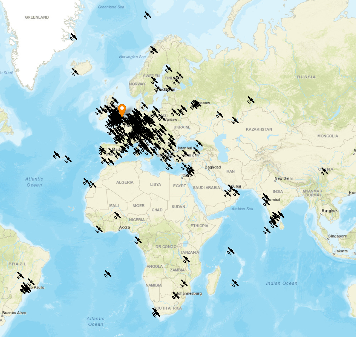
The flow generates two maps, one for voice / CW /Satellite contacts and the other for WSJT-X FT4/8 contacts. Every pin on the map is colour coded by band with satellite contacts being denoted by a satellite icon.
Each pin / icon on the map is clickable and reveals the data of the QSO being displayed.
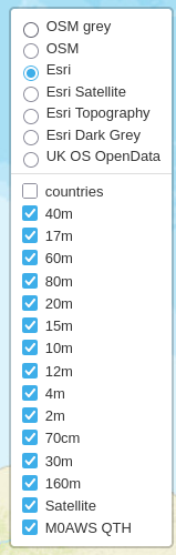
In the top right-hand corner of the map there is a drop down layermenu that allows the viewer to filter by band thus reducing the number of icons on the screen at any one time.
Seeing the data presented on a map really brings my logs alive. An example of this is that I had no idea I’d worked so many stations in India on the QO-100 Satellite.
The small icons in the pins show a microphone for SSB/FM/FreeDV contacts and a downwards pointing triangle in a box for CW contacts. Sadly I couldn’t find a Morse key icon in the collection available.
M0AWS filtered view of QO-100 Satellite contacts
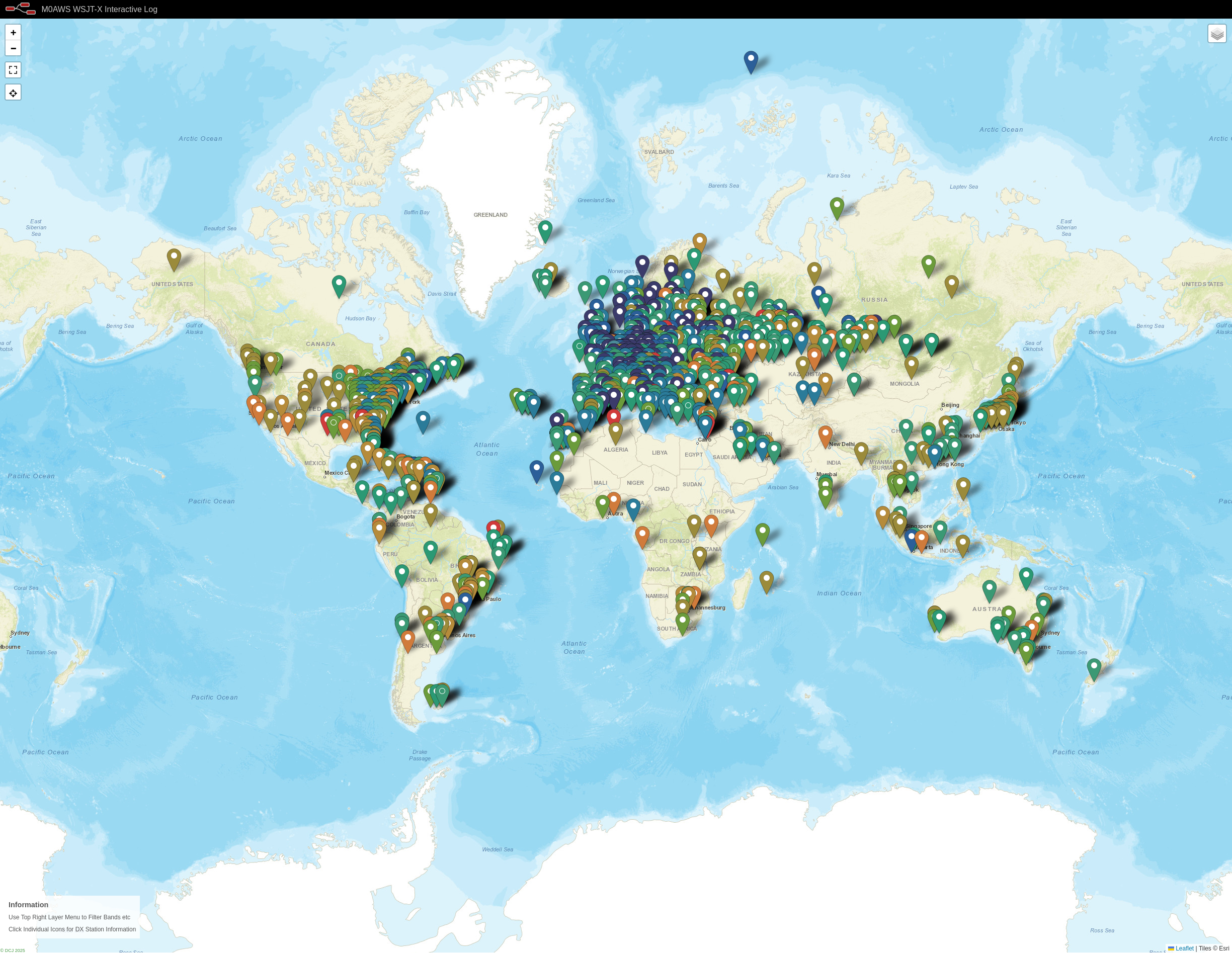
I only use FT4/8 for testing new antenna designs however, it’s interesting to see the global coverage accomplished with this weak signal mode.
M0AWS WSJT-X FT4/8 Interactive Log World Map
Once I’ve finished rewriting the format generic payload function I will make the flow available for download here so that others can also create an interactive view of their radio logs.
If you want to have a look at the maps and try them out for yourself, they are available under the Logs menu above.
This Node-Red instance is running in a virtual machine (VM) on a 16GB RAM RaspberryPi 5 that is also running a number of other VMs at the same time so, it’s safe to say it’s not heavy on CPU and will run on the older Pi4 as well.
Back in January 2025 I wrote an article about a little RadioBerry Project I’d started that was based around a very old Philips 170A-15 receiver from 1946.
The idea of the project was to build a nice shortwave receiver for the radio shack based around the RadioBerry HAT on a RaspberryPi 4 housed in a vintage receiver cabinet.
The project has taken longer than I imagined due to getting side-tracked by other projects that I already had ongoing.
With the original internals removed there’s plenty of room inside for the RadioBerry, RaspberryPi 4 and the small 15w audio amplifier. The audio is delivered via a pair of Celestion speakers that I had that were originally part of an old surround sound TV system.
Power distribution is achieved very simply using a multi-plug adapter that also has USB A connections in it. The whole thing is then powered via one 240v mains cable.
The screen fits over the original opening for the glass tuning display and is held in place by two mounting screws on the rear of the LCD panel.
I purchased some new speaker grill cloth from Amazon and remade the speaker grill front with cut outs for the speakers. It looks really tidy and matches the rest of the bakelite cabinet nicely.
1946 Philips 170A-15 Shortwave Receiver RadioBerry HAT on RaspberryPi 4
To finish the project off I need to purchase 3 rotary encoders so that I can have a VFO knob and two more knobs for other things (to be determined). The Volume control is already in place with the original knob fitted to it. It will be nice to complete the 4 knob line up.
I had to make a couple of fittings top and bottom to hold the original rear panel in place but, it worked out just fine and I only had to fit an SO239 antenna connector and ethernet RJ45 port so that it can be connected to my local LAN.
Receiving radio Caroline on 648Khz
The audio quality from the little RadioBerry and 15w amp is pretty good. With the speakers hidden nicely behind the refurbished speaker grill the project looks quite tidy!
It also makes a great receiver for the HAM bands with it’s coverage of 100Khz to 30Mhz.
The DL1YCF Enhanced fork of PiHPSDR works really well on the touchscreen and provides a modern control interface to the RadioBerry HAT.
Listening to the 20m HAM Band
I’ll drop a final article once I have purchased the 3 rotary encoders to fill the 3 remaining holes in the front of the cabinet.
For the last week or so I’ve been playing with a RadioBerry HAT for my RaspberryPi computer. The RadioBerry is a cut down version of the Hermes Lite 2 with just 20mW output power and separate TX and RX antenna ports. It’s a really neat little package that sits on top of a RaspberryPi4/5 and creates a neat little HF transceiver.
RadioBerry HAT
I initially started with the RadioBerry HAT on my Pi5 but, I soon realised that the software really doesn’t work well at all on the Pi5. I’m not 100% sure as to why but, for some reason it holds one core at 100% continuously. It seems that the RadioBerry software is single threaded. The end result is that on the Pi5 you cannot use a sample rate above 9600 before the IQ stream starts to stutter.
By contrast, installing the RadioBerry software onto a Pi4 it performs perfectly upto the maximum sample rate of 384000 without any stuttering. I’ll need to spend some time going through the source code to try and determine why it doesn’t work correctly on a Pi5.
Whilst going through the source I discovered that the developer has put some code in that collects data from the running computer and sends it to the developer’s website. Some of this data is then made public via his website, http://www.pa3gsb.nl/radioberry/api/read.php
One of the things displayed on the website is the Mac address of the RaspberryPi on which the RadioBerry is running. This is a security risk and should never be done!
The most annoying thing is that this is done without authorisation. The installation doesn’t state that it’s going to collect data every time you start your RaspberryPi computer nor does it offer the ability to opt out. It also doesn’t inform the user that it’s going to pass the data on to a third party. In some cases it even collects HAM Radio Callsign and location data and displays it on a public website, a clear breach of the UK/European Data Protection Law.
Finding spyware in open source software is really poor and something most open source developers would never consider doing.
To this end I have disabled the spyware in the version of the RadioBerry software that I am using and am making it available to everyone else to use via this blog.
So, to install the RadioBerry software you just need to download the installation script and run it in a terminal on your RaspberryPi computer.
The script will download the modified source code, compile it and install it on your RaspberryPi ready for you to use.
I encourage everyone that downloads the script and the source code to take a look at it and ensure you are happy with it. It’s important to know what you are running on your computer and what it does.
You can find the spyware code in the register.c file (It’s all commented out with “//” marks). The function now doesn’t pass any data at all to the public website.
I hope some of my readers who are experimenting with the RadioBerry transceiver find this useful.
I will soon be publishing an article on an enhanced version of PiHPSDR from DL1YCF to use with the the RadioBerry to complete the project.
Important Update:
There is an issue with the RadioBerry code that renders it useless if you use a kernel later than the version shown below:
Updating the O/S Kernel to any version later than the version shown above will stop the RadioBerry software from working. Recompiling of the code also fails due to the Kernel update and at the time of writing this cannot be fixed without a code rewrite by the original developer.
I also recommend that once you have built a working RadioBerry on a RaspberryPi 4 you should disable the automatic updates of the O/S to stop the system from failing in the future.
You can disable the automatic updates by entering the following commands into a terminal:
This antenna modelling session came about after a conversation with Michael, DK1MI on the Matrix. I believe the antenna design was originally done by Artur, M0PLK with reviews being on EHAM.
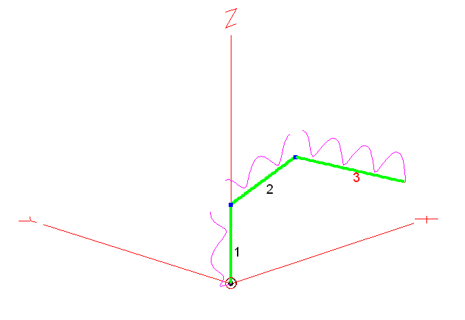
The antenna takes the form of a simple inverted triangular loop with a 5.8m flat top and two diagonals each 5.6m long coming down to a point. The antenna is fed in the centre of the flat top with 450 Ohm open ladder line and a 4:1 Balun. This antenna will require an ATU on all bands as the modelling shows a very wide range of impedances at the feed point.
Multi-Band Delta Loop Antenna View
The design seems to suggest using two fixed aluminium tubes with the wire fed up through them for the two diagonal elements of the antenna however, it would probably be easier to use a pair of collapsable fibre glass poles (Not Carbon fibre) with the wire attached via some clips or tape.
I decided to model the antenna with the top horizontal wire 10m above ground putting the point of the triangle 5.2m above ground. I felt this was an achievable height for most HAMs. Lowering the antenna will raise the resultant angle of maximum radiation on all bands.
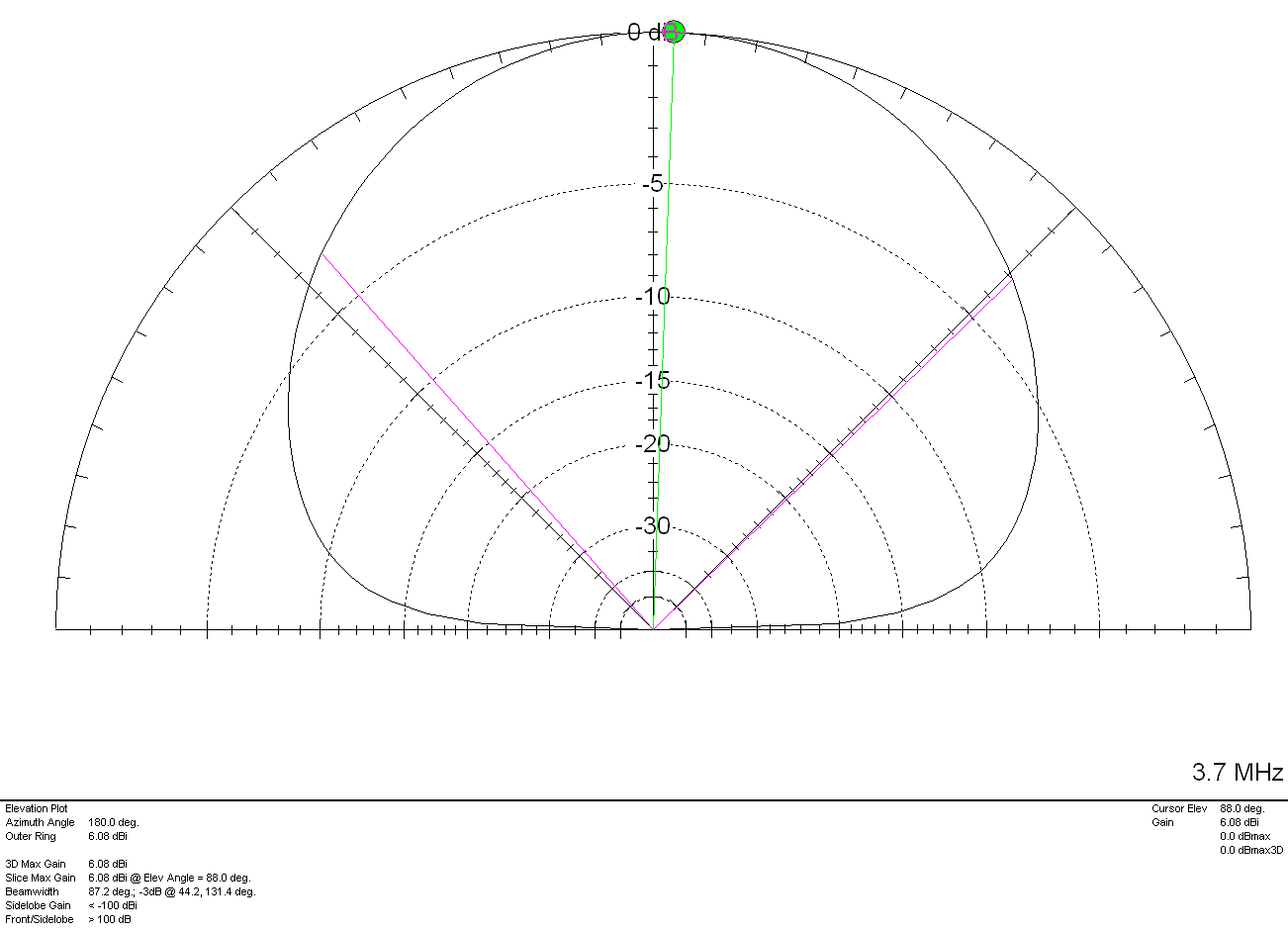
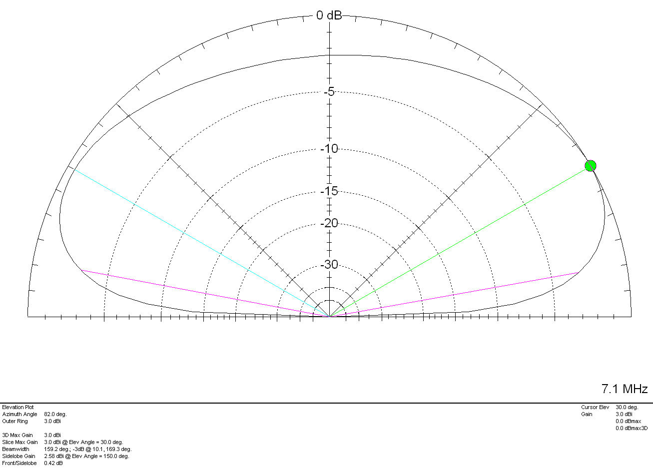
Looking at the 2D Far Field Plots (2DFFP) the antenna radiates through the loop as expected with a higher radiation angle on the lowest band and the lowest radiation angle on the highest band. The antenna is of course bi-directional and so could be rotated just 180 degrees to obtain global coverage.
On the 30m band the antenna has a very high angle of maximum radiation making it ideal for short distances. There is a little gain to be had at 25 degrees however, this is nowhere near the maximum but, will possibly aid working longer distances. A maximum gain of 5.31dBi is obtained at 72 Degrees on the 30m band.
Multi-Band Delta Loop Antenna 30m 2D Far Field Plot
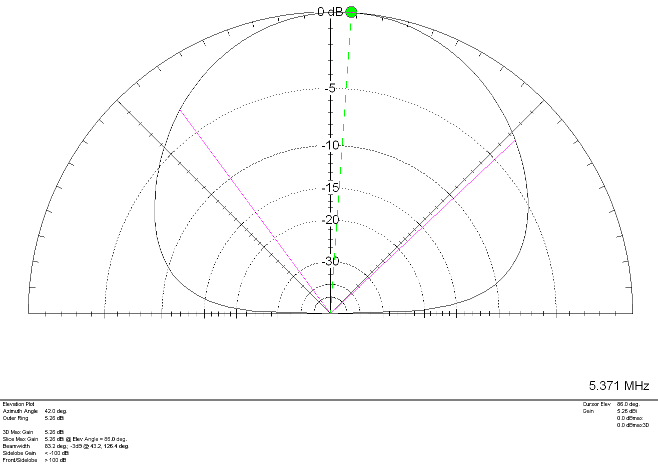
On the 20m band the 2DFFP is fairly similar to that of the 30m band but, with 5.57dBi gain at a lower angle of 34 Degrees. This will provide excellent results on medium distance contacts and reasonable results on the long haul.
Multi-Band Delta Loop Antenna 20m 2D Far Field Plot
Once above 14Mhz things start to get more interesting. From the 17m band upwards the radiation pattern changes quite drastically and starts to provide some excellent gain at relatively low angles. This will improve the antenna’s DX performance considerably on the higher bands.
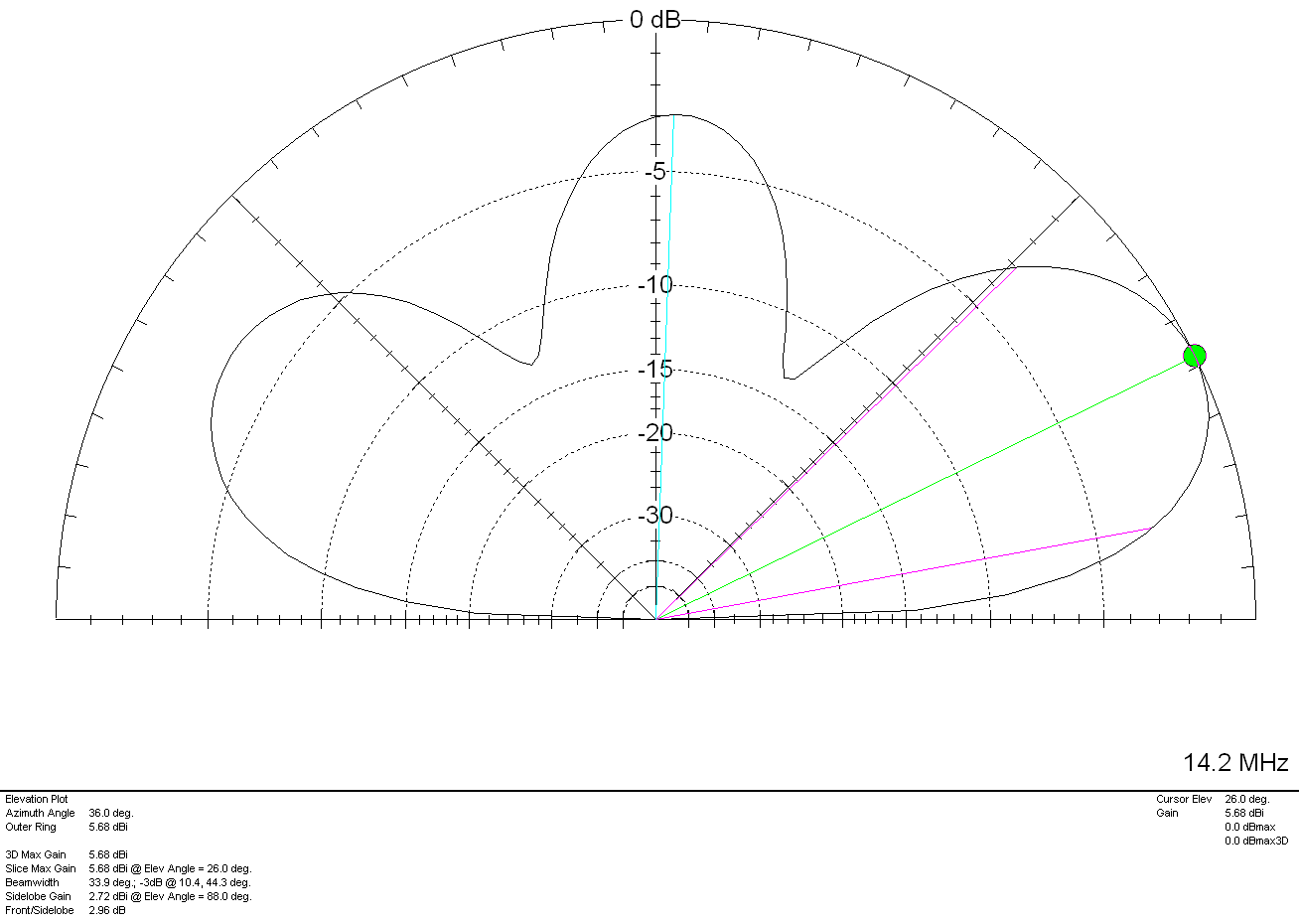
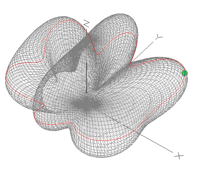
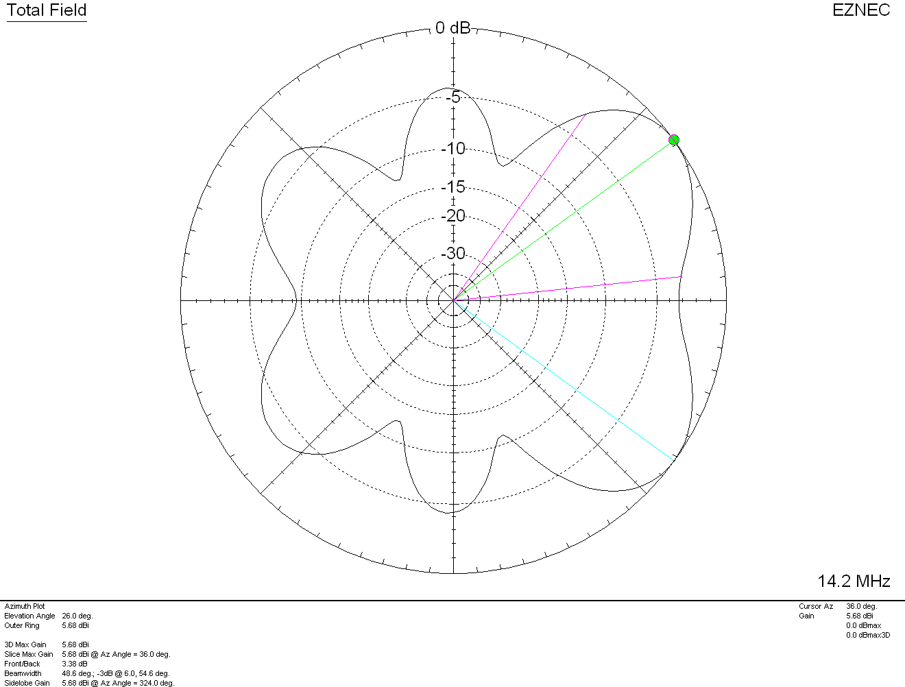
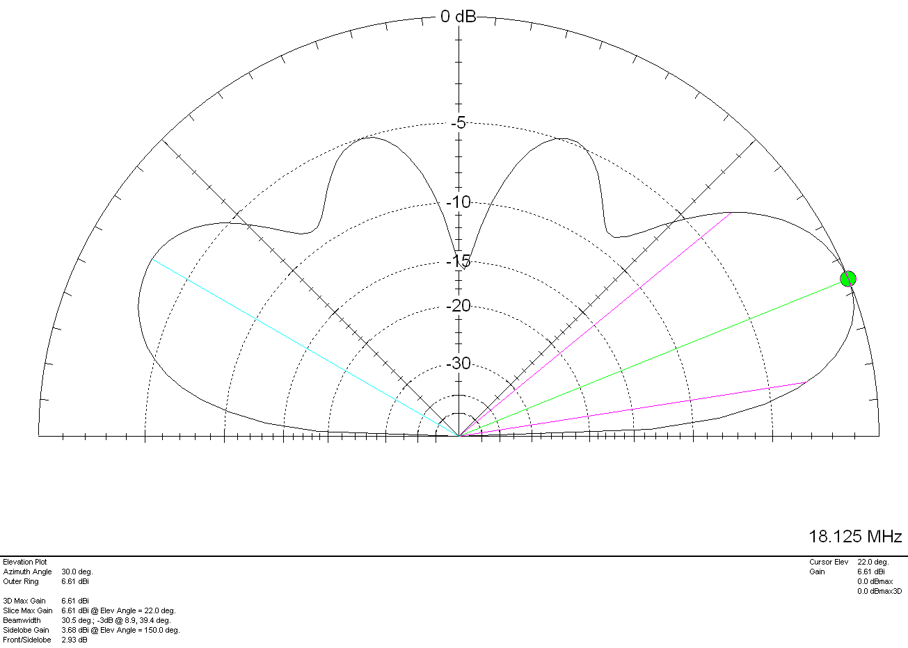
Looking at the 17m band the angle of maximum radiation is now down to 26 degrees with a gain of 7.64dBi. At 12 degrees there is a gain of 4.59dBi. This radiation pattern will make this antenna ideal for the medium to long haul contact with very little interference from NVIS signals.
Multi-Band Delta Loop Antenna 17m 2D Far Field Plot
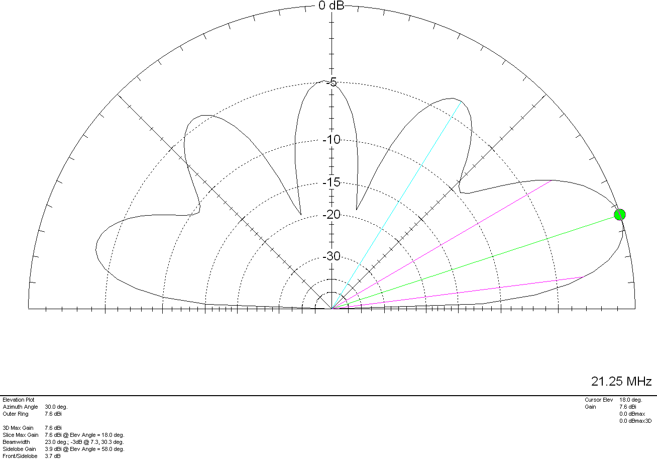
The 15m band follows the trend with the angle of max radiation now down to 22 degrees with a max gain of 8.54dBi. Even at 10 degrees there is a gain of 5.34dBi which will be very welcome for DXing. There is slightly more near vertical incident skywave (NVIS) radiation on the 15m band and so the antenna should provide short, medium and long haul contacts with the latter being favoured.
Multi-Band Delta Loop Antenna 15m 2D Far Field Plot
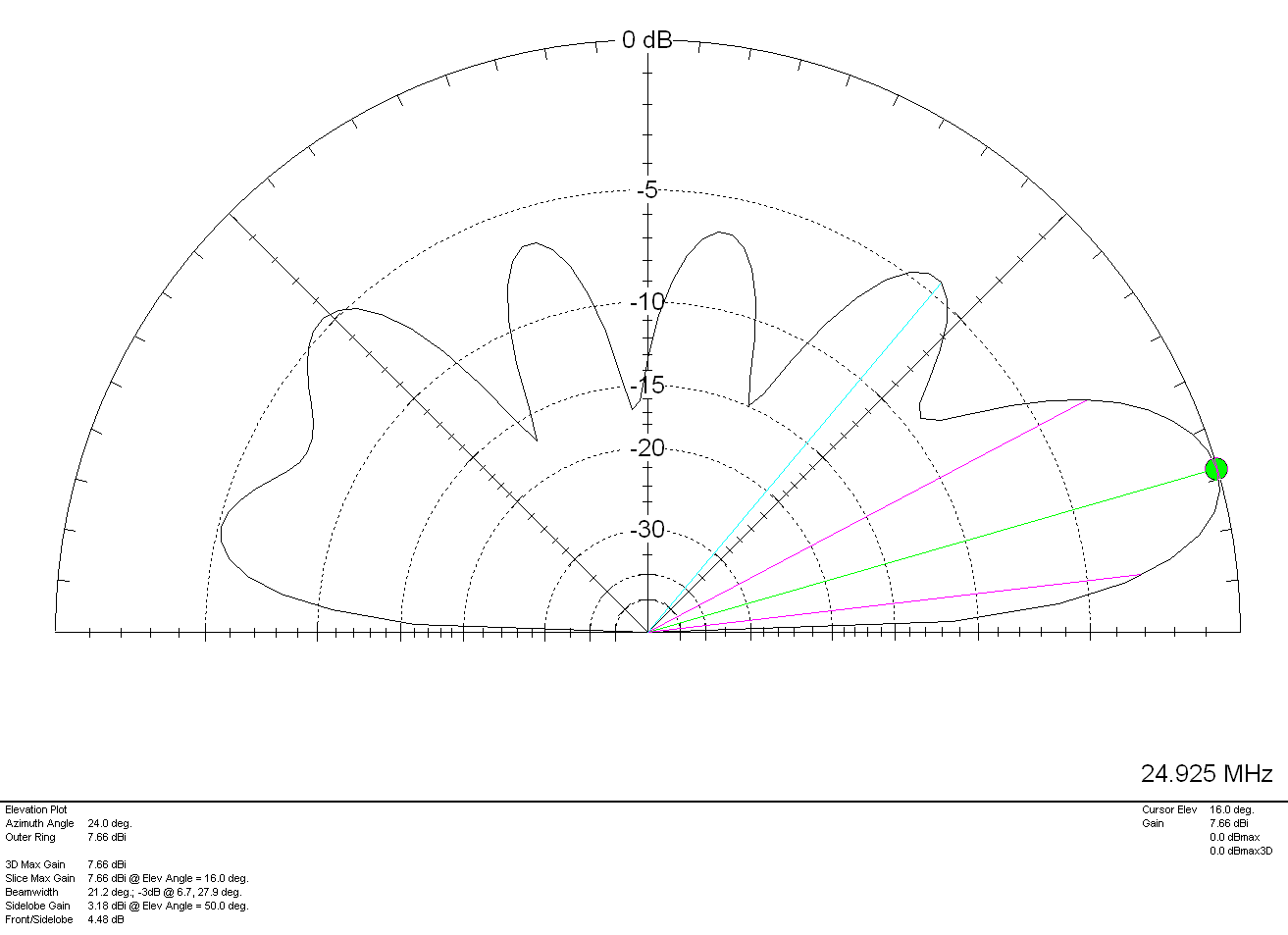
Moving up to the 12m band the angle of maximum radiation now comes down to 18 degrees with a gain of 8.61dBi. There is also 5dBi of gain to be had at 8 degrees which is ideal for DXing. Unfortunately there is slightly more NVIS radiation on the 12m band than there is on the 15m band. I’m sure with a little change in height this could be reduced such that the antenna provides only low angle radiation.
Multi-Band Delta Loop Antenna 12m 2D Far Field Plot
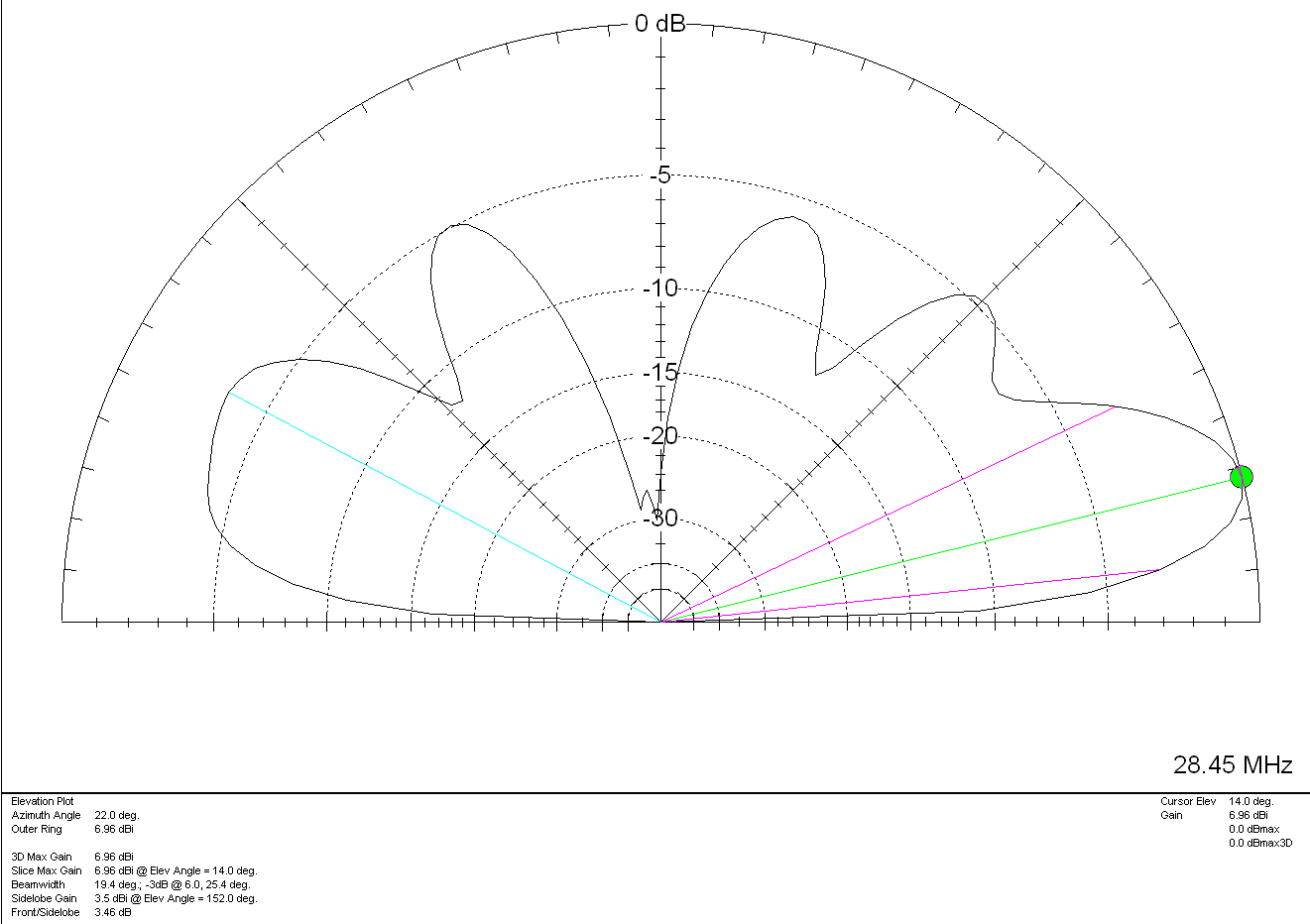
Finally we reach the 10m band, this is where the antenna has the lowest angle of maximum radiation. With 8.56dBi gain at 16 Degrees, 5.59dBi at 8 degrees and a much reduced NVIS radiation. This antenna should be excellent for the long haul on 28-29Mhz. (It would also make an excellent 11m/CB antenna).
Multi-Band Delta Loop Antenna 10m 2D Far Field Plot
It’s interesting to note the similarities between this multi-band delta loop design and my Bi-Directional Slot Fed Antenna design. They both exhibit very similar radiation patterns and gain figures with the Slot Fed Antenna providing slightly more gain and an even lower angle of maximum radiation on the supported bands.
Overall this easy to construct multi-band delta loop antenna would be ideal for the HAM that just wants a single antenna for 30m and upwards or is looking to go portable. The only disadvantage is that a good Remote Auto ATU is required to provide matching of the antenna to the 50 ohm coax at the feed point. Something like the LDG RT100 would be an ideal ATU choice for this application and would remove the losses caused by having a high SWR on the coax feed to the antenna.
Using an ATU in the radio in the shack isn’t going to provide the same results as the coax cable from the antenna to the shack will become part of the antenna and will be detrimental to the antenna performance. It will also create high losses on the coax feed to the antenna due to high SWR being present over the length of the coaxial feed.
Following on from the article I wrote about the performance of my multi band vertical antenna I’ve now put together a table showing it’s performance on each band as experienced over a period of 18 months.
It’s interesting to note the antenna wavelength measurements on each band as 13m (43FT) seems to be an almost perfect length for a simple multi band vertical HF antenna with excellent DX capabilities.
M0AWS 13m (43FT) Multiband Vertical HF Antenna Info (Click to Enlarge)
Looking at the information you can see that performance on the 160m band is poor. This is to be expected as the antenna is far too short for a band with such a long wavelength. I knew this would be the case from the outset and never planned to use this antenna on the 160m band. I’ve included the data here just for completeness. If you’re looking for a reasonable 160m band antenna that can fit into an average UK garden then take a look at my Inverted-L antenna article.
Performance on the 80m band is surprisingly good considering the antenna is only 1/6th of a wavelength long. With contacts into Indonesia achieved using relatively low power levels this antenna surprised me with its performance on the 80m band. A 1/4 wavelength antenna would of course perform better but, like all multi band vertical antennas for the HF bands there is always a compromise.
On the 60m band the antenna is pretty much a 1/4 wave vertical, it works great on this band and I’ve had a lot of fun chasing DX in the winter months. With the longest contact being into Brazil at 6144 miles this antenna performs extremely well for such a simple design.
On the 40m band performance is better still. With the antenna being just over a 1/4 wavelength long the point of max current is above ground level making this a very good DX antenna. With multiple contacts into Australia at distances over 10,000 miles this antenna is the ideal 40m band DX chaser for small gardens.
Moving up onto the 30m band this antenna now begins to really shine. Being a half wave long on 30m the point of max current is half way up the wire lowering the angle of radiation considerably. This results in excellent global coverage with contacts into Australia being a breeze. With the longest distance achieved being 11,776 miles into New Zealand this really is the goto antenna for fans of the 30m band with small gardens. This antenna easily out performs my 30m band Delta Loop design whilst giving better global coverage.
On the 20m band this antenna performs very well indeed. Considering it’s 3/5th of a wavelength long which is a strange length to have, it’s no slouch. Global coverage is excellent and working into Australia is relatively easy. I’ve yet to work into New Zealand on the 20m band using this antenna but, that’s mainly due to me not being on air at the right times. Best distance worked so far on this band is 10,656 miles.
On the 17m band the antenna is 3/4 wavelength long. This is a very useful length and easy to tune as it presents pretty much 50 ohm impedance at the feed point. Performance is simply stunning on 17m, if you can hear the DX you can work them. I am amazed at how well this antenna works on this band. It seems to have a low angle of max radiation making it excellent for chasing DX stations. Giving me my first contacts into Alaska and New Zealand this is my goto antenna for the 17m band.
On the 15m band this antenna is 7/8th of a wavelength long. Performance doesn’t feel as good as it does on 17m but, with the longest distance achieved being 8023 miles there’s really no reason to doubt it. With only 87 contacts being made on this band due to the fact that I always get trapped chasing DX on the 17m band and never make it any further up the bands, I’m sure this antenna will perform extremely well long term on 21Mhz. I just need to make more effort to get on this band.
The 12m band is one of the bands I didn’t expect this antenna to perform well on. Being 1 and 1/8th wavelengths long it’s not a length that you would normally consider using for an antenna however, performance is excellent. This is most likely due to the point of max current being a fair way up the wire resulting in a low angle of maximum radiation. DXing is great fun with this antenna on the 12m band and it’s surprised me time and time again at how easily I’ve been able to work DX stations. With the best distance worked so far being into the Falkland Islands at 7973 miles, this antenna has huge potential on this band. Like the 15m band, I need to make an effort to spend more time on the 12m band and see how far I can push this antenna.
Finally we reach the dizzy heights of 28Mhz on the 10m band where the antenna is 1 and 1/4 wavelengths long. Again this is a useful length as it presents almost 50 ohm impedance at the feed point. DX performance on the 10m band is good. It’s probably very good however, like the 15m and 12m bands, I rarely make it up onto the 10m band and so I’ve not really given the antenna the time to prove itself at 28Mhz. My best distance worked so far on this band is 4872 Miles into the USA but, I’m sure I could easily do better if I committed more time to it.
I’ve pretty much covered all the good points of this simple multi band antenna so, now let’s look at the not so good points.
If you’re in the UK and are looking to work other UK stations then this antenna isn’t for you. Like all vertical antennas there isn’t much in the way of NVIS radiation and so you’ll find UK stations just won’t hear you. You’ll also often find you won’t hear UK stations at all due to the null at the top of the antenna that attenuates signals arriving from high/very high angles. For me this is fine as I wanted an antenna that was focused on DXing as much as possible.
From 10Mhz upwards the antenna also isn’t that good for working stations in nearby Europe. Most of the time you will only hear European stations that are more than 1000 – 1500 miles away, anything closer just doesn’t appear in the receiver. On the 15m and 12m bands often you will never hear European stations at all, only DX stations. This does of course reduce the QRM from UK/EU stations considerably making it easier to work those weak/QRP DX stations.
So as you can see, 13m (43FT) of vertical wire is probably one of the best lengths you can possibly use for a multi band vertical HF antenna especially if like me, you have a small garden to squeeze your antennas into. I don’t like to say it but, this could be the magical length we’re all looking for when making a multi band HF vertical antenna.
Tuning of the 13m (43FT) vertical antenna is achieved using my CG3000 remote auto ATU. I initially started off using my home-brew Pi-Network ATU but, changed over to the CG3000 so that in the winter months I don’t have to run out into the rain and wind to change bands. It’s important to note that the ATU must be at the base of the wire and not in the radio shack. It’s also important to note that I have 4 x 20m long radials connected to the CG3000 along with an earth spike at the base of the wire. This combination of ground and tuner works incredibly well with the ATU tuning on each band with ease in less than 3 seconds. I’ve also not had any issues with the CG3000 attempting to retune whilst in the middle of a QSO, once it’s initially tuned it doesn’t retune again until I either change band or make a large change in frequency.
The achieved SWR on all bands is <1.5:1 except for 160m where it is 1.8:1.
Since I put together my Inverted-L antenna and Pi-Network ATU I’ve been having a lot of fun on the low bands.
Getting back onto 160m has been most enjoyable and I’ve now had over 100 ‘Top Band’ contacts with distances covered as far as 3453 Miles into Sosnovoborsk Asiatic Russia.
I must admit I am amazed at the distances achieved on the 160m band as the antenna isn’t very high above ground level when compared to a single wave length on 160m.
M0AWS Inverted-L Antenna View
The Inverted-L antenna at the M0AWS QTH was designed purely around the size of the back garden. Using a couple of 10m Spiderpoles the vertical section of the antenna is 10m tall and the horizontal section is 28m long. Naturally the antenna resonates around 2.53Mhz but, can be tuned to resonate anywhere on any band using the Pi-Network ATU I built that is situated at the base of the vertical section of the antenna.
Looking at the far field plots for the antenna on each band we see that as we move higher in frequency the radiation pattern becomes more complex and the radiation angle gets lower, exactly what we would expect from such an antenna. The antenna runs pretty much North/South in the garden ( X axis on the diagram above) and so we would expect the antenna to radiate East/West (Y axis on the diagram above) however, this isn’t always the case.
M0AWS Inverted-L Antenna 160m 3D Far Field PlotM0AWS Inverted-L Antenna 160m 2D Far Field Plot
(Click Far Field Plots for full screen view)
On 160m the antenna favours the South (-X Axis) and presents some usable high angle gain although, from using the antenna you would never know this to be the case as it seems to have pretty good all round coverage. With the best distance of 3453 Miles being covered to the East into Asiatic Russia the antenna performs well even though the far field plot is slightly biased to the South.
M0AWS Inverted-L Antenna 80m 3D Far Field PlotM0AWS Inverted-L Antenna 80m 2D Far Field Plot
On the 80m band the Inverted-L antenna becomes a cloud warmer and exhibits very high angle radiation. On 80m the antenna is ideal for NVIS Inter-G propagation and is great for rag chewing with other UK/Near EU stations.
M0AWS Inverted-L Antenna 60m 3D Far Field PlotM0AWS Inverted-L Antenna 60m 2D Far Field Plot
Looking at the far field plots for the 60m band once again the antenna provides lots of high angle gain however, there is also some very useable lower angle gain that has proven to be excellent for working long hauls into North America and east into Central Asia. On the 60m band during the day the antenna is excellent for Inter-G chatting, using just 20w-40w I can very easily chat with other UK HAMs even when the band is noisy.
M0AWS Inverted-L Antenna 40m 3D Far Field PlotM0AWS Inverted-L Antenna 40m 2D Far Field Plot
Moving on up to the 40m band we find the far field plot starts to get a little more complex. Looking at the 3D plot you’d think that the antenna favoured the South (-X Axis) however, in reality it favours the NorthWest with both some high and low angle gain. This antenna has proven to be excellent for DXing into North America on 40m but, has also been great for DXing into South America getting great signal reports from stations in Panama at a distance of 5415 Miles. During the day NVIS propagation is excellent and I find I can chat with other UK and near EU stations with ease using just 25w.
M0AWS Inverted-L Antenna 60m/40m Global Coverage
Above is a screen shot from PSKReporter showing stations that have heard me on the 40m and 60m bands. As you can see, global coverage is excellent with stations as far as Australia and New Zealand hearing me on the 40m band and stations on the West Coast USA hearing me on the 60m band. I was also pleased to see I was heard in Africa on both bands, a region of the world I would like to get more contacts from.
M0AWS Inverted-L Antenna 30m 3D Far Field PlotM0AWS Inverted-L Antenna 30m 2D Far Field Plot
On the 30m band the Inverted-L antenna starts to exhibit two lobes with gain to the NorthEast and NorthWest. This makes the antenna ideal for working into the USA and Australia/New Zealand over the North Pole. Working US stations is a breeze with relatively low power and I almost got a contact with New Zealand during the evening greyline but, unfortunately the DX station dropped out before I managed to get my signal report back to him. As time goes on I’m sure the antenna will more than prove itself on the 30m band.
So far I’ve not ventured above the 30m band with the Inverted-L antenna as I’ve really been enjoying access to Inter-G chats on 80m, 40m and 60m and chasing DX on 160m, 60m, 40m and 30m. I need to venture up onto the higher bands before the long winter nights settle in and the higher HF bands close for the winter season.
Looking at the far field plots on the higher HF bands the antenna has huge potential as it provides some nice low angle radiation in useful directions.
M0AWS Inverted-L Antenna 20m 3D Far Field PlotM0AWS Inverted-L Antenna 20m 2D Far Field Plot
On the 20m band the far field plot starts to get much more complex with lobes at many different angles. The main gain lobe is to the NorthEast towards the USA and is at a fairly low angle and so this antenna should be great for working stateside on the 20m band. There are also lobes to the NorthEast and so hopefully working VK/ZL over the pole should also be possible. As I said above I’ve not yet used the antenna above the 30m band and so at this time cannot confirm performance but, it looks promising.
M0AWS Inverted-L Antenna 17m 3D Far Field PlotM0AWS Inverted-L Antenna 17m 2D Far Field Plot
The 17m band also looks promising with a similar far field plot as the 20m band but, with lower angle of maximum radiation and more gain. It will be very interesting to test this antenna on 17m especially since the noise level is below S0 and I can very easily hear the weakest of stations on this band.
M0AWS Inverted-L Antenna 15m 3D Far Field PlotM0AWS Inverted-L Antenna 15m 2D Far Field Plot
Once again the 15m band looks very similar to the 17m band, low angle radiation but, with a slightly more complex far field plot.
M0AWS Inverted-L Antenna 12m 3D Far Field PlotM0AWS Inverted-L Antenna 12m 2D Far Field Plot
The 12m band far field plots continue the theme with the angle of maximum radiation slightly lower than on the 15m band and slightly more gain. This antenna should be great for chasing the DX on the very quiet 12m band.
M0AWS Inverted-L Antenna 10m 3D Far Field PlotM0AWS Inverted-L Antenna 10m 2D Far Field Plot
Finally the 10m band is very similar to the 12m band in that the far field plots show low angle gain albeit with an even more complex radiation pattern.
I originally put this antenna up so that I could work Inter-G on the low bands but, it has proven to be a much more worthy antenna than I originally thought it would be. I need to spend more time with this antenna on the bands above 30m to really see how it performs on the higher HF bands but, so far I’m really pleased with it’s overall performance on all the bands tested to date.
I can highly recommend using FT8 to test new antennas. With PSKReporter and my own NodeRed World Map WSJT-X interface I can see realtime the antenna performance on each band. FT8 is an extremely useful tool when it comes to testing antennas to see if they perform as per the modelling and can often provide some performance surprises!
I’ve had this antenna model for ages now but, never got round to putting it onto the website until Alex, GM5ALX was talking about making one the other day whilst chatting on the QO-100 satellite.
The 20m band delta loop follows exactly the same design principles as all the other delta loop designs I’ve already put on the website. They are designed such that they present a 50 ohm impedance at the feed point and thus have no requirement for complex impedance matching circuits/transformers.
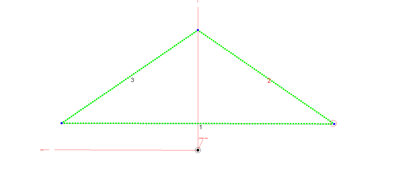
M0AWS 20m Band Delta Loop Antenna – Antenna View
The dimensions for the antenna are as follows:
Wire 1 – Horizontal exactly 1m above the ground for its entire 10.2m length. Wires 2 & 3 are exactly 6.18m long each with the top being 4.5m above the ground.
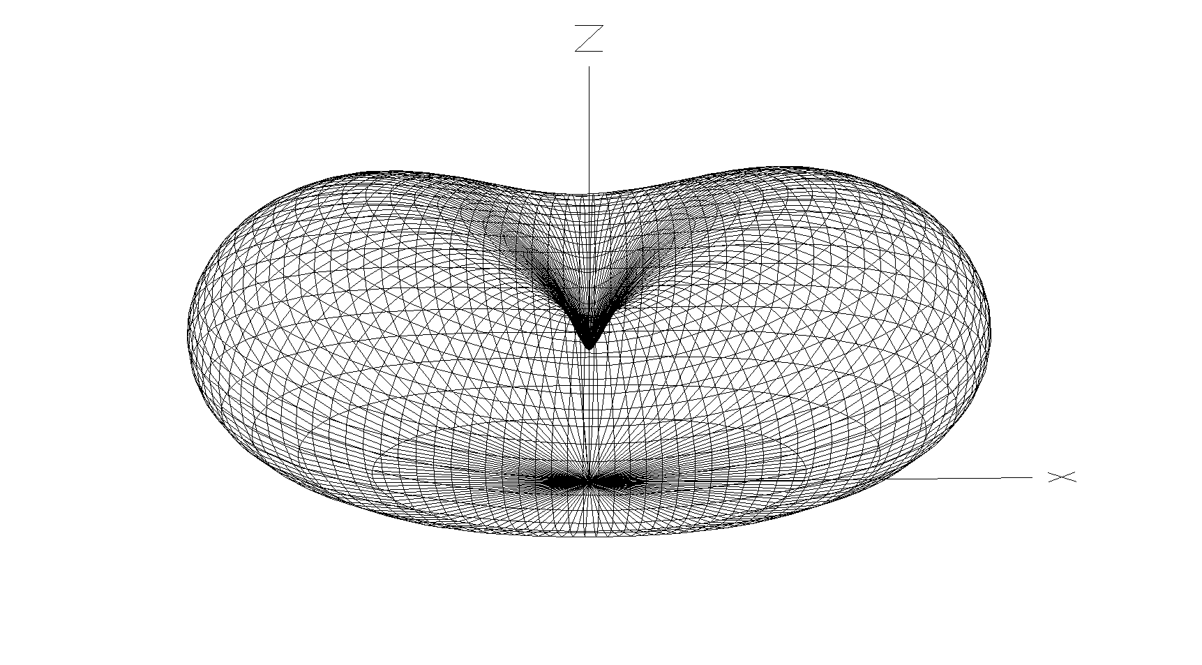
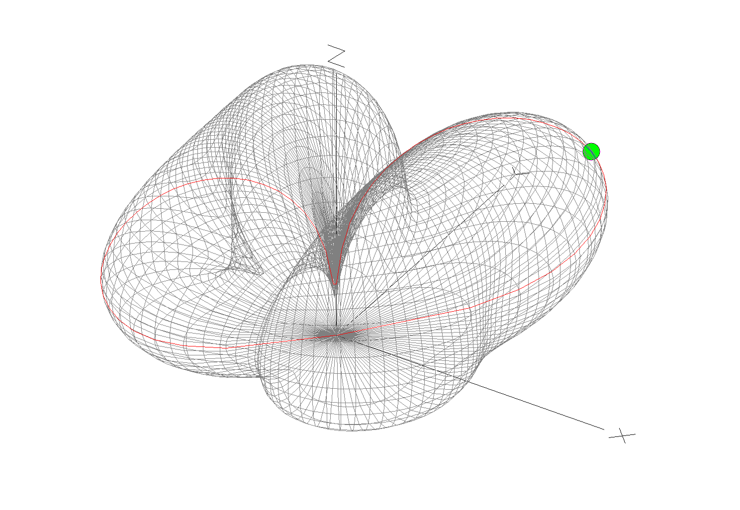
M0AWS 20m Band Delta Loop Antenna – 3D Far Field Plot
The 3D far field plot shows a typical delta loop radiation pattern with the maximum radiation through the loop and a deep null in the centre.
M0AWS 20m Band Delta Loop Antenna – 2D Far Field Plot
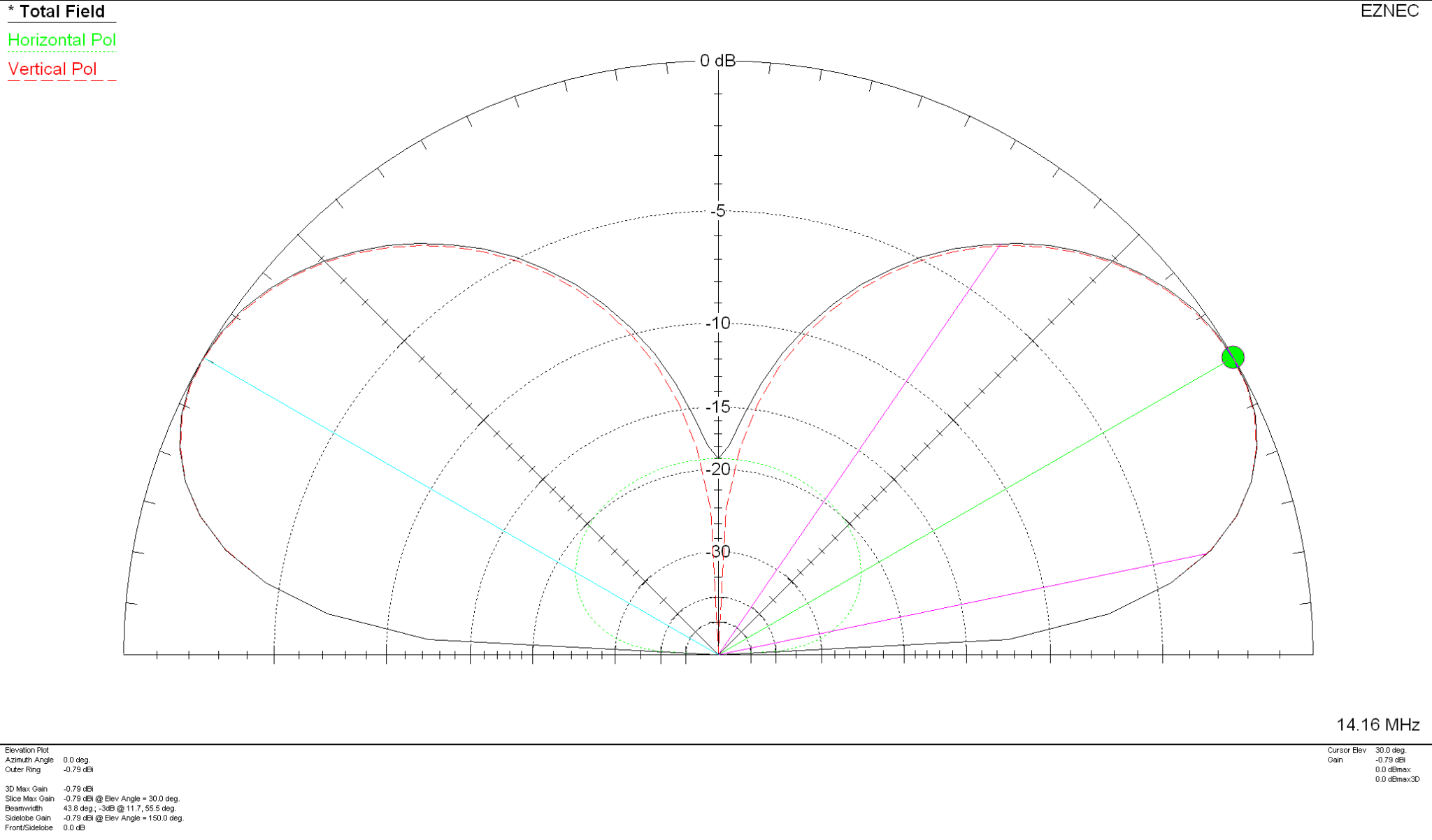
The 2D elevation plot shows that the antenna will give a maximum gain of -0.79dBi at 30 degrees when used over average/poor soil types. If like me you use your Delta Loop antennas on the beach then the antenna will present considerably more gain as it will benefit from the salt water reflection.
If you want to lower the angle of maximum radiation and increase the gain over average ground just raise the antenna up so that the top is around 7m above ground. This will give a much lower angle of radiation and improve the gain figure by 2-3dBi. Don’t forget that if you raise the antenna the point of resonance will also rise in frequency and so you may need to shorten the wires a little to get the point of resonance back to where you want it.
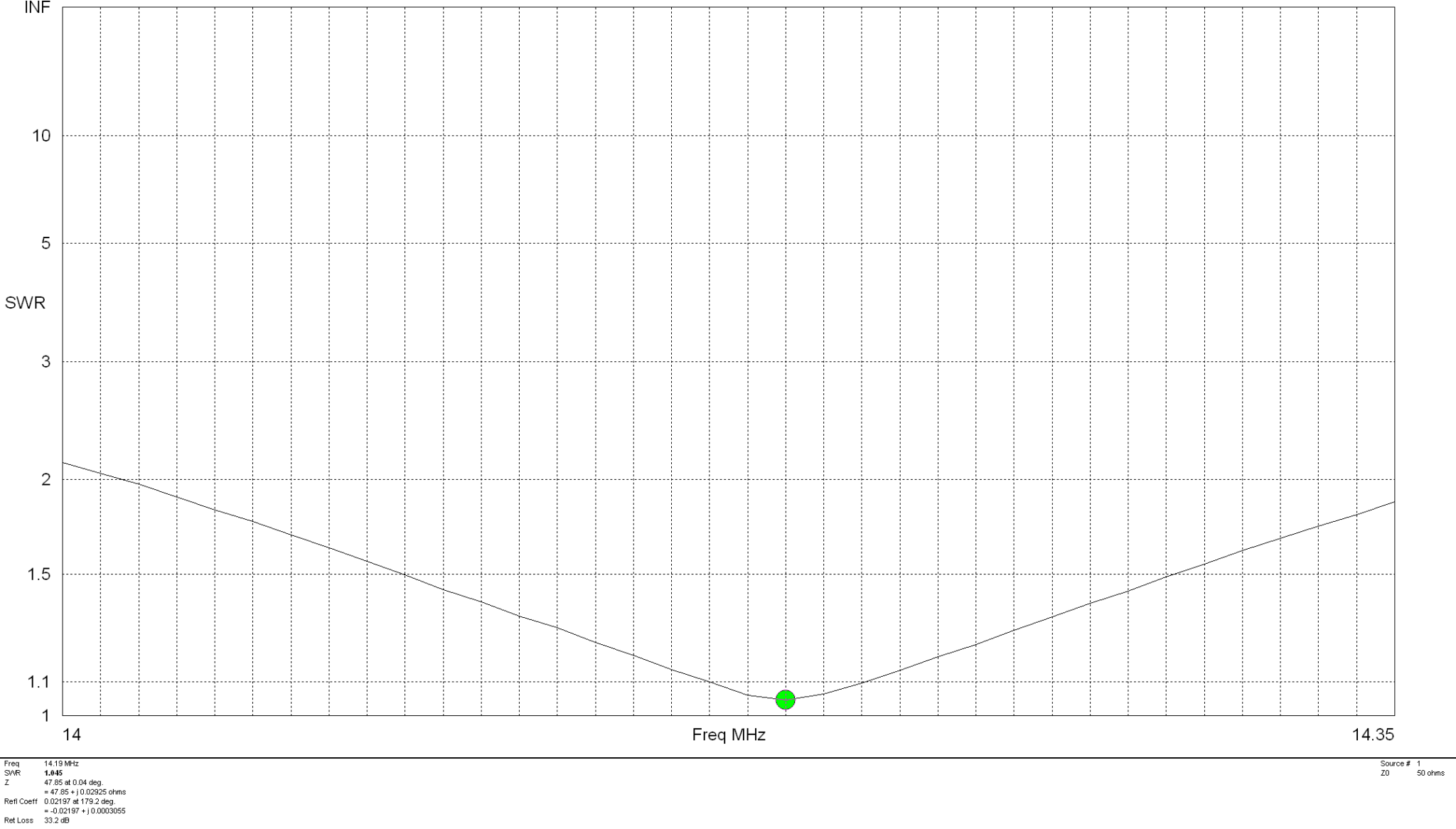
The SWR plot shows that the antenna will have a fairly wide bandwidth and match to 50 ohm coax extremely well. The antenna is designed to be fed in one of the lower corners via a 1:1 balun for best results.
M0AWS 20m Band Delta Loop Antenna – SWR Curve
Summary:
Total Wire Length: 22.56m Horizontal Wire Length: 10.2m @ 1m above ground Diagonal Wire Lengths: 6.18m Wire Dia: 2.5mm Height at Centre: 4.5m Feed Type: 1:1 Balun in bottom corner (Can use coax if necessary) Impedance: 50 Ohm SWR: <1.5:1 at resonance
Many years ago I had an MFJ-259B antenna analyser that I used for all my HF antenna projects. It was a simple device with a couple of knobs, an LCD display and a meter but, it provided a great insight into the resonance of an antenna.
MFJ-259B Antenna Analyser
Today things have progressed somewhat and we now live in a world of Vector Network Analysers that not only display SWR but, can display a whole host of other information too.
Being an avid antenna builder I’ve wanted to buy an antenna analyser for some time but, now that I’m into the world of QO-100 satellite operations using frequencies at the dizzy heights of 2.4GHz I needed something more modern.
If you search online there are a multitude of Vector Network Analysers (VNAs) available from around the £50.00 mark right up to £1500 or more. Many of the VNAs you see on the likes of Amazon and Ebay come out of China and reading the reviews they aren’t particularly reliable or accurate.
After much research I settled on the JNCRadio VNA 3G, it gets really good reviews and is very sensibly priced. Putting a call into Gary at Martin Lynch and Sons (MLANDS) we had a long chat about various VNAs, the pros and cons of each model and the pricing structure. It was tempting to spend much more on a far more capable device however, my sensible head kicked in and decided many of the additional features on the more expensive models would never get used and so I went back to my original choice.
Gary and I also had a long chat about building a QO-100 ground station, using NodeRed to control it and how to align the dish antenna. The guys at MLANDS will soon have a satellite ground station on air and I look forward to talking to them on the QO-100 transponder.
M0AWS – JNCRadio VNA 3G PackagingM0AWS – JNCRadio VNA 3G in box with connectors and cables
Initially I wanted to check the SWR of my QO-100 2.4GHz IceCone Helix antenna on my satellite ground station to ensure it was resonant at the right frequency. Hooking the VNA up to the antenna feed was simple enough using one of the cables provided with the unit and I set about configuring the start and stop stimulus frequencies (2.4GHz to 2.450GHz) for the sweep to plot the curve.
The resulting SWR curve showed that the antenna was indeed resonant at 2.4GHz with an SWR of 1.16:1. The only issue I had was that in the bright sunshine it was hard to see the display and impossible to get a photo. Setting the screen on the brightest setting didn’t improve things much either so this is something to keep in mind if you plan on using the device outside in sunny climates.
(My understanding is that the Rig Expert AA-3000 Zoom is much easier to see outside on a sunny day however, it will cost you almost £1200 for the privilege.)
A couple of days later I decided to check the SWR of my 20m band EFHW vertical antenna. I’ve known for some time that this antenna has a point of resonance below 14MHz but, the SWR was still low enough at the bottom of the 20m band to make it useable.
Hooking up the VNA I could see immediately that the point of resonance was at 13.650Mhz, well low of the 20m band and so I set about shortening the wire until the point of resonance moved up into the band.
JNCRadio VNA3G showing 20m Band EFHW Resonance
With a little folding back of wire I soon had the point of resonance nicely into the 20m band with a 1.35:1 SWR at 14.208Mhz. This provides a very useable SWR across the whole band but, I decided I’d prefer the point of resonance to be slightly lower as I tend to use the antenna mainly on the CW & FT4/8 part of the band with my Icom IC-705 QRP rig.
Popping out into the garden once more I lengthened the wire easily enough by reducing the fold back and brought the point of resonance down to 14.095Mhz.
JNCRadio VNA3G showing 20m Band EFHW Resonance 14Mhz to 14.35Mhz Sweep
The VNA automatically updated the display realtime to show the new point of resonance on the 4.3in colour screen. I also altered the granularity of the SWR reading on the Y axis to show a more detailed view of the curve and reduced the frequency range on the X axis so that it showed a 14Mhz to 14.35Mhz sweep. With an SWR of 1.34:1 at 14.095Mhz and a 50 Ohm impedance, the antenna is perfectly resonant where I want it.
It’s interesting to note that the antenna is actually useable between 13.5Mhz and 14.5Mhz with a reasonable SWR across the entire frequency spread. Setting 3 markers on the SWR curve I could see at a glance the SWR reading at 14Mhz (Marker 2) , 14.350Mhz (Marker 3) and the minimum SWR reading at 14.095Mhz (Marker 1).
I’ve yet to delve into the other functionality of the VNA but, I’m very happy with my initial experience with the device.
More soon …
We use cookies to ensure that we give you the best experience on our website. If you continue to use this site we will assume that you are happy with it.