Following on from my previous article on using Node-Red to build interactive log maps I’ve now reworked the flow to make it more efficient with less Javascript.
The original flow had a function that handled the issue of FT4 contacts being recorded in two different ways depending on which app you use for your FT4/8 operations.
<mode:4>MFSK <submode:3>FT4
or
<mode:8>MFSK FT4
The code I wrote to handle this wasn’t particularly elegant and so I decided to remove the code entirely and just use a simple change node.
M0AWS New node to handle FT4 more efficiently
This is the great thing about Node-Red, there’s always more than one way to do something.
With this fix in place and the old code stripped out of the format generic payload function, the new flow is much tidier and easier to comprehend.
M0AWs Updated ADI Log Map flow
With testing complete and the two maps now live on my website the flow is finally ready for release into the wild.
If you fancy presenting your ADIF logs in a more visual, interactive format then just download the flow below and import it into your Node-Red flow editor.
Don’t forget that you will need to change the path to the log files in the file read nodes to suit your setup and change the location data in the My QTH trigger to match your callsign and location. Other than this the flow should just work.
I’ve not been on the radio much over the last few weeks as I’ve had my head down other radio related rabbit holes.
One of the rabbit holes is a Node-Red project to make my online logs a little more interactive. For sometime now my logs have been displayed on my website as nicely formatted, searchable HTML pages however, they don’t really allow the viewer (myself included) to see the global coverage of all the contacts so, I decided to write a Node-Red flow that would do just that.
M0AWS Interactive Log Flow
The flow itself isn’t too complicated and basically consists of reading in the individual ADIF formatted log files, processing the data and then sending the data in the correct format to the map node for display.
I’ve had to write a few functions to handle the processing of the ADIF formatted data but, these aren’t particularly complex and are fairly easy to understand even if like me, you’re not a Javascript programmer.
The flow is working perfectly however, I’m in the process of reworking the format generic payload function to reduce the amount of code and make it more efficient.
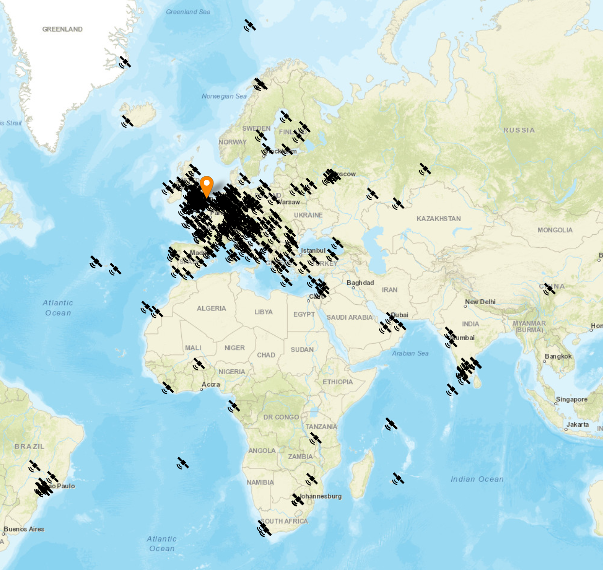
M0AWS SSB / CW / FreeDV Interactive Log World Map
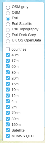
M0AWS Interactive Log Map Layers Menu
The flow generates two maps, one for voice / CW /Satellite contacts and the other for WSJT-X FT4/8 contacts. Every pin on the map is colour coded by band with satellite contacts being denoted by a satellite icon.
Each pin / icon on the map is clickable and reveals the data of the QSO being displayed.
In the top right-hand corner of the map there is a drop down layermenu that allows the viewer to filter by band thus reducing the number of icons on the screen at any one time.
Seeing the data presented on a map really brings my logs alive. An example of this is that I had no idea I’d worked so many stations in India on the QO-100 Satellite.
The small icons in the pins show a microphone for SSB/FM/FreeDV contacts and a downwards pointing triangle in a box for CW contacts. Sadly I couldn’t find a Morse key icon in the collection available.
M0AWS filtered view of QO-100 Satellite contacts
I only use FT4/8 for testing new antenna designs however, it’s interesting to see the global coverage accomplished with this weak signal mode.
M0AWS WSJT-X FT4/8 Interactive Log World Map
Once I’ve finished rewriting the format generic payload function I will make the flow available for download here so that others can also create an interactive view of their radio logs.
If you want to have a look at the maps and try them out for yourself, they are available under the Logs menu above.
This Node-Red instance is running in a virtual machine (VM) on a 16GB RAM RaspberryPi 5 that is also running a number of other VMs at the same time so, it’s safe to say it’s not heavy on CPU and will run on the older Pi4 as well.
I’ve recently been trying out the FreeDV RADEv1 digital voice mode on the HF bands with great success. The audio quality is astounding when compared to the normal analog SSB mode. Using only 20w I’ve been surprised how successful I’ve been talking to stations in the UK and Europe as can be seen in my FreeDV Log.
FreeDV has been around for quite a few years with development being funded by an ARDC grant and financial sponsorship from the Software Freedom Conservancy.
“FreeDV is a suite of digital voice modes for HF radio. Our flagship mode is the Radio Autoencoder (RADE). You can run RADE using a free GUI application for Windows, Linux and macOS that allows any SSB radio to be used for high quality digital voice.“
And the most important part:
“All software is open source, released under the (a) GNU Lesser Public License version 2.1 (GUI and legacy FreeDV modes) and two-clause BSD license (RADE).“
FreeDV running under KDE-Plasma on Kubuntu PC
Looking at the digital voice (DV) community in the HAM Radio world, it’s stuffed full with proprietary DV modes from small software houses and black box transceiver manufacturers with no real OpenSource alternatives, until now.
Installing FreeDV is pretty simple regardless of which operating system (O/S) you use. Being a Linux user I grabbed the AppImage from the website and set about reading up on how it works and how it is configured.
I decided to take the two sound card approach since I have 2 USB sound cards connected to my shack Kubuntu Linux PC.
Configuring the audio routing isn’t straight forward as both the receive and transmit audio to/from the radio needs to be routed via the FreeDV app. To make this even more complicated I am using my Hermes Lite 2 SDR transceiver and PiHPSDR software, a complete OpenSource/OpenHardware Amateur Radio Station.
M0AWS FreeDV and PiHPSDR Audio Routing Diagram
Trying to clearly describe the audio routing using words alone would be impossible and very confusing so, I put together the diagram above.
Using two USB sound cards I’ve configured the system such that USB Sound Card 1 (an old Griffin iMic USB sound device) handles just the audio from/to the headphones and microphone. All the audio at this point in the system is analogue.
The second USB sound card, a cheap Plug and Play (PNP) USB audio device from Amazon, handles all the digitised signals from/to FreeDV and PiHPSDR.
Taking this 2 sound card approach keeps confusion to a minimum and separates the analogue and digital components of the audio routing.
So, how does this translate to the FreeDV and PiHPSDR audio settings?
Transmit Audio Chain
FreeDV Transmit Audio Settings
Starting at the beginning of the transmit audio chain, let’s look at the transmit audio settings in FreeDV.
Looking at the FreeDV Transmit audio settings screenshot below we can see that the Input From Microphone to Computer device is set to:
This is the digitised audio output from FreeDV (via USB Sound Card 2) to PiHPSDR and is used as the transmit audio that is sent to the Hermes Lite 2 transceiver.
FreeDV Transmit Audio Settings
PiHPSDR Transmit Audio Setting
To complete the transmit audio path we next need to look at the PiHPSDR transmit audio setting.
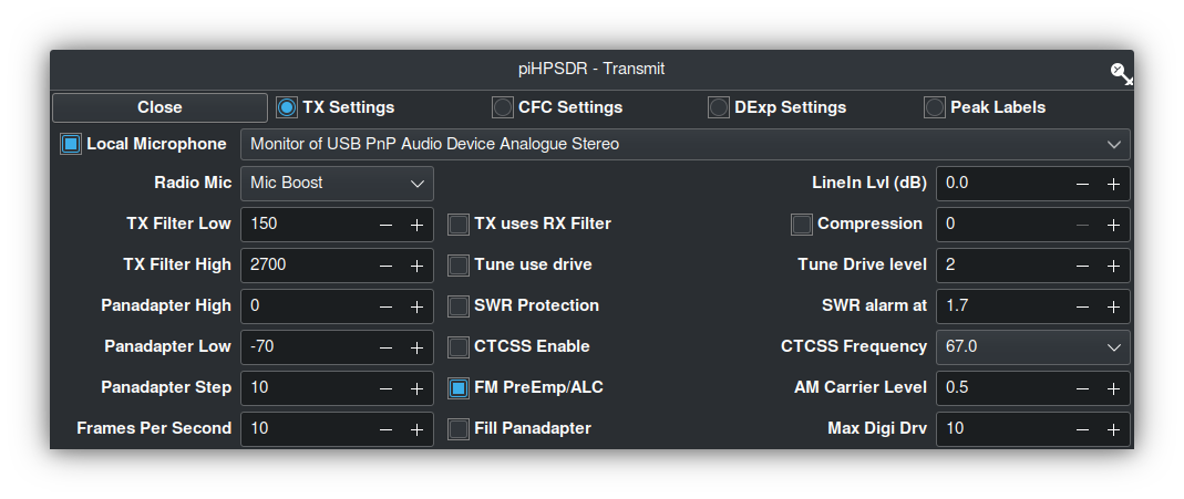
PiHPSDR Transmit Audio Settings
As can be seen in the screenshot above, the Local Microphone device in PiHPSDR is set to the Monitor of USB PnP Audio Device Analogue Stereo.
This effectively routes the digitised output audio from FreeDV (Output From Computer to Radio device) to the Input audio of PiHPSDR.
The reason for using the Monitor audio feed is because FreeDV does not recognise the Mic Input in PiHPSDR as a valid output device for FreeDV to use, hence we just need to monitor the FreeDV output device and use it as our input audio device in PiHPSDR.
This completes the transmit audio chain.
Receive Audio Chain
PiHPSDR Receive Audio Setting
Starting at the beginning of the receive audio chain we first look at the PiHPSDR receive audio setting.
PiHPSDR Receive Audio Setting
In the screenshot above we can see that the receive audio output from PiHPSDR is set to USB PnP Audio Device Analogue Stereo (USB Sound Card2). This is the DX station’s digitised audio as received by the Hermes Lite 2.
FreeDV Receive Audio Settings
Next let’s look at the receive audio setting in FreeDV.
FreeDV Receive Audio Settings
The Input To Computer from Radio device is set to the monitor of the USB PnP Audio Output Device:
This is the analogue audio output on the iMic USB Sound card (Sound Card 1) that routes the analogue audio to the headphones and completes the receive audio chain.
Summary
The audio routing required by FreeDV can appear very daunting when first attempting to configure it on the Linux platform but, hopefully the diagram and screenshots above will help in understanding the complete end-to-end audio chain that is required to make this mode work.
PiHPSDR can of course be replaced by your black box radio CODEC entries that will appear in the device lists shown above if you have your radio connected via USB. The config is basically the same but, just uses a different device instead of USB sound card 2 shown in the diagram above.
I hope this article is useful to those wanting to try FreeDV on the Linux platform and I look forward to hearing you on RADEv1.
RaspberryPi computers are now moving into the realm of being powerful enough to replace the traditional desktop PC. My most recent purchase, a RaspberryPi 500+ is proof of this as it has been my daily desktop PC since it’s arrival.
One of the things I use heavily are virtual machines. They’re great for developing, prototyping and running new services. With the ability to snapshot, rollback and backup in an instant, virtualisation helps to reduce the development and test time for many of the programs and services that I’m playing with.
With RaspberryPi computers now supporting 16GB of RAM and M.2 SSD drives there is no reason for not taking advantage of virtualisation.
To this end I decided to test running some virtualised loads on my new 500+ with the plan to deploy to 16GB Pi5’s with SSD drives in place of more expensive Intel based computers.
On my Intel based machines I use QEMU, KVM and Virt-Manager to manage the multitude of virtual machines (VMs) I have running here. Since this is a solid, high performance platform for running VMs I decided to take the same route on the 500+
Installing the necessary packages is extremely simple, just one simple apt command:
# Main ethernet
# Setup Bridge called br1 on eth0
allow-hotplug eth0
iface eth0 inet manual
auto br1
iface br1 inet static
address 192.168.0.100
network 192.168.0.0
netmask 255.255.255.0
broadcast 192.168.0.255
gateway 192.168.0.1
dns-nameservers 192.168.0.5
bridge_ports eth0
bridge_stp off
#
#
Once this is done reboot your RaspberryPi and check you have access to your local LAN and of course the internet. You will now also inherit the two new groups that you added yourself to above.
Note: If you are using NetworkManager open the network settings app and create a bridge on eth0. You can also use the nmtui copmmandline app if you prefer.
At this point you’re ready to create your first virtual machine.
It’s important to have an arm64 version of Linux in ISO format that you can use to install into your VM. My preferred distro is Debian and so I downloaded the Debian 13 Arm64 netinst ISO from the debian.org website.
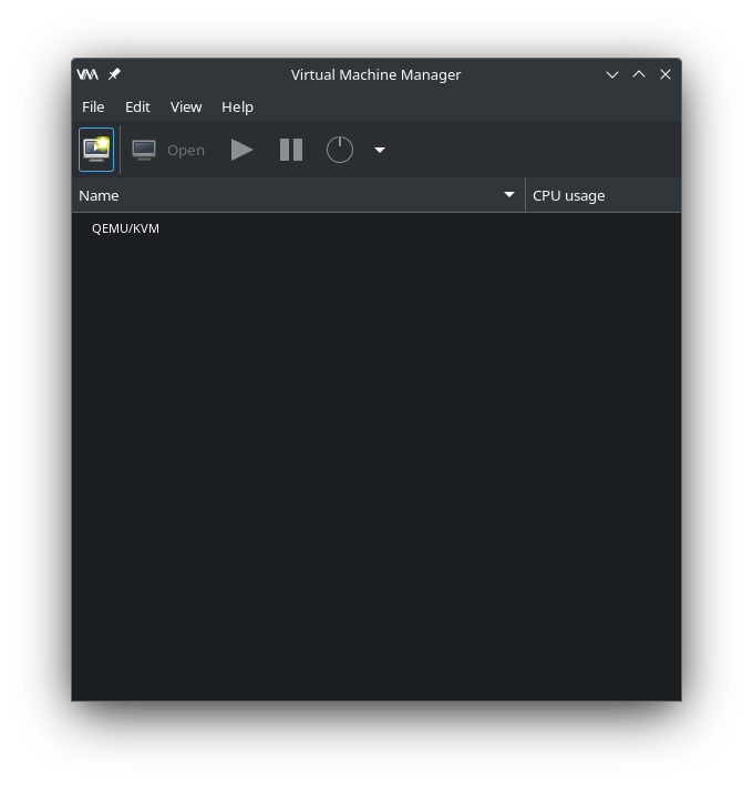
From the main menu start “Virtual machine Manager” or on the commandline type:
virt-manager
QEMU Virtual Machine Manager
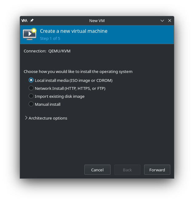
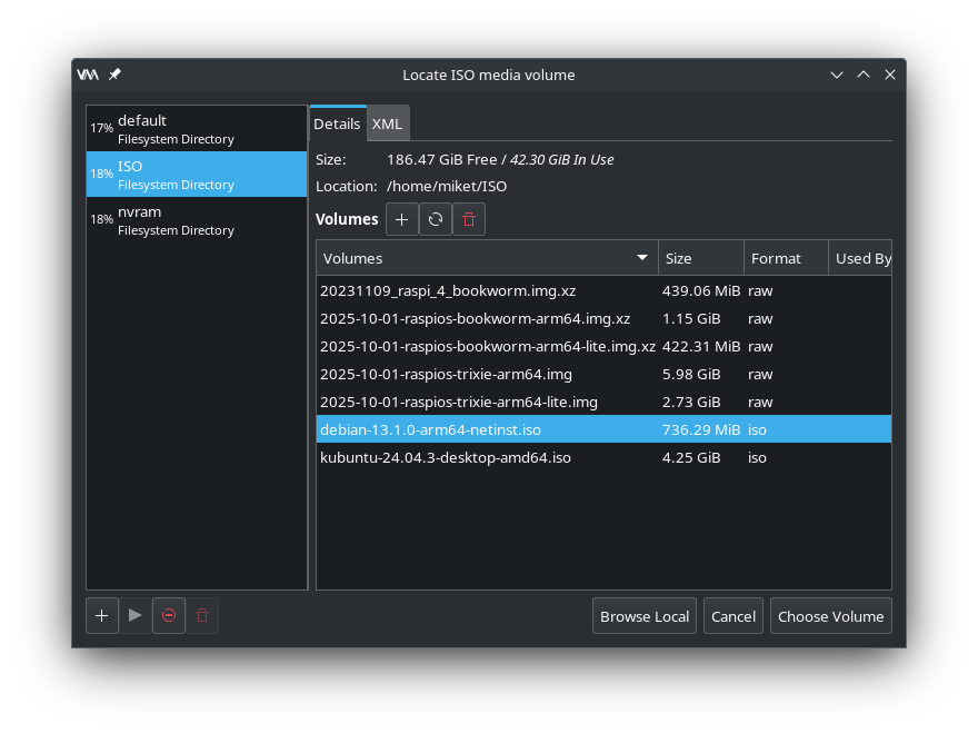
Click the Create new VM button and then navigate to where you saved your ISO file and select it as the installation media.
Virtual Machine Manager – Local install mediaVirtual Machine Manager – Select ISO file
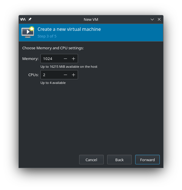
Once you’ve chosen your ISO you’ll need to configure the actual VM. Start by setting the amount of RAM and number of virtual CPUs you want the VM to have.
Virtual Machine Manager – Configure RAM and CPU
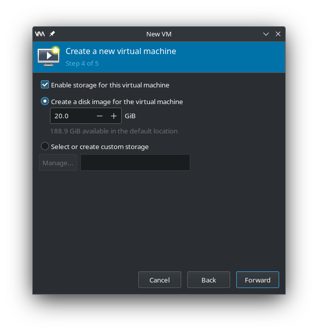
Next set the size of the virtual disk that the VM will use.
Virtual Machine Manager – Create virtual disk
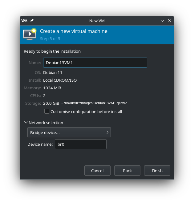
Finally, give the VM a name and set its network device to br0 as created above. Click finish and your VM will boot.
Virtual Machine Manager – Name VM and select bridge interface
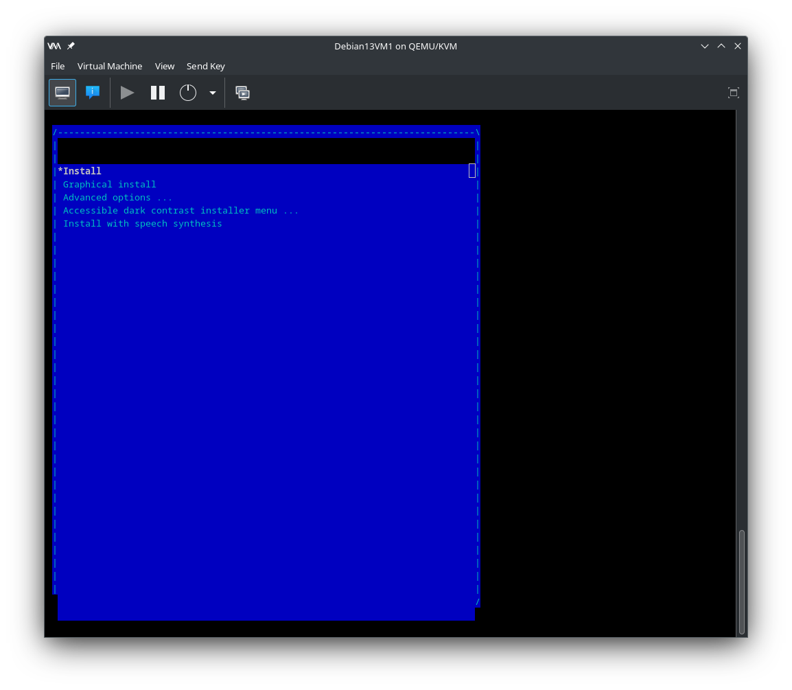
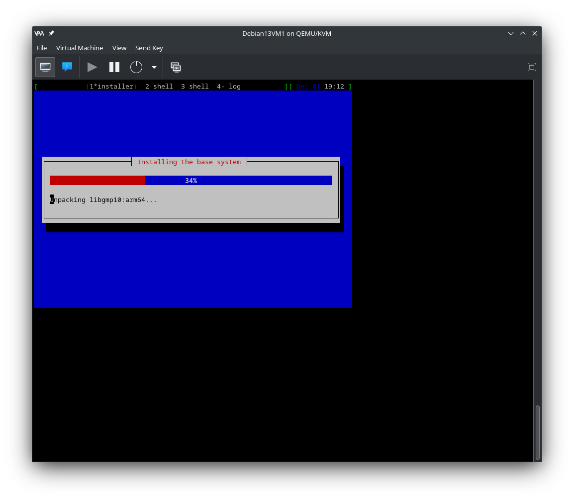
Now it’s just a case of going through the standard Debian install process to build your Debian VM.
Once the installation is complete and the VM has rebooted you will have a functional Debian computer ready to use for whatever you like, just like a physical PC but, in virtual form. You’ll find that the VM runs as fast as the actual physical machine thanks to the kernel based virtualisation.
I’ve spent some considerable time of late coding a new version of adi2html that I use to convert my ADIF log files into online web pages for all my HAM Radio logs.
The old version that I wrote quite some time ago was written using BASH shell which was quick and easy at the time but, as the logs grew in size it got slower and slower to process the ever increasing number of log entries.
Now I’m retired I have the time to revisit these things and write better, more modern versions of my various programs that run silently in the background.
Writing the new version of adi2html in Python3
It’s taken a little over a week to put this code together, test and debug it, I don’t like to rush these things!
I’ve finally put v1.2 into production today.
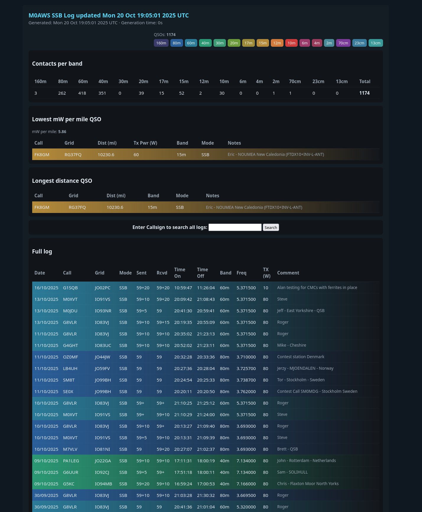
The 585 lines of code produce a very nice, modern looking web page and can be used to convert any ADIF file into HTML. The code is extremely quick, taking less than a second to process almost 2500 log entries, a huge improvement over the old version of adi2html.
New look M0AWS Log web page
All of my logs are available here on my blog under the Logs menu above, feel free to have a look at them.
I now need to rewrite the log search functionality so that it uses the same format of presentation for the results.
Since RaspberryPi are now forcing users of its SBC to use RaspberryPi OS 13 (via the RaspberryPi Imager tool) instead of the reliably stable Debian 11 or 12 several issues have come to light.
Firstly if like me you run most of the your Pi4/5 SBCs headless/lights out you’ll notice that networking is now ridiculously managed via Network Manager and Netplan.
This is a ridiculous method of managing such a simple device, it’s over complicated, messy and ill thought out. Yet another classic example of change for the sake of change and not to actually improve things.
This combination of Network Manager (often referred to as Network Mangler for good reason) and Netplan is fraught with bugs. Try setting a second IP address on an interface and you’ll find it doesn’t work. nmtui will show the ip address as being configured however, netplan never actually puts the config into play.
Having to use nmtui on the command line to manage ethernet interfaces is also ridiculous. Its badly laid out menu system takes an age to get through to do the simplest of config changes. What’s wrong with just editing the /etc/network/interfaces file?
After much frustration trying to configure the ethernet interface on my headless Pi5 I decided to get rid of this hideous method of managing ethernet interfaces and put it back to using the simple interfaces file.
I’ve documented the steps just in case anyone else wants to do the same.
Step 1: Make sure the traditional networking stack is installed:
# Example /etc/network/interfaces for Ethernet (eth0) with static IP:
#
# Loopback
auto lo
iface lo inet loopback

# Ethernet
auto eth0
iface eth0 inet static
    address 192.168.1.10
    netmask 255.255.255.0
    gateway 192.168.1.1
    dns-nameservers 1.1.1.1 8.8.8.8
Example for DHCP:
auto eth0
iface eth0 inet dhcp
If you use Wi-Fi:
auto wlan0
iface wlan0 inet dhcp
    wpa-ssid "YourSSID"
    wpa-psk "YourPassword"
Step 5 – Enable the traditional networking service
The /etc/network/interfaces method works perfectly on Pi 5 and is lighter weight and ideal for embedded or headless servers.
If you later reinstall NetworkManager, it will override interfaces again unless you mark them as unmanaged in /etc/NetworkManager/NetworkManager.conf.
You can still use ifup / ifdown commands manually for control.
You now have your Pi running the classic, lightweight networking stack which is ideal if you use your Pi as a 24/7 server like I do.
Note: This method is still supported on RaspberryPi Debian 13 but, it’s no longer the default.
As a final note, if you want to add a second IP Address to your Ethernet interface it’s extremely simple to define in the /etc/network/interfaces file. I’ve created an example of how to do this below for reference.
# Loopback
auto lo
iface lo inet loopback

#
# Primary interface - static IP
#
auto eth0
iface eth0 inet static
    address 192.168.1.10
    netmask 255.255.255.0
    gateway 192.168.1.1
    dns-nameservers 1.1.1.1 8.8.8.8

#
# Secondary IP on same interface
#
auto eth0:1
iface eth0:1 inet static
    address 192.168.1.11
    netmask 255.255.255.0
Check both IP Addresses appear on the same interface:
ip a show eth0
For the example above you’ll see:
inet 192.168.1.10/24
inet 192.168.1.11/24
Finally, if like me you use lm-sensors to keep check on how hot your Pi is running you’ll find that the sensors command no longer works, it just throws a segmentation fault. This is a nuisance as I use this as part of my Node-Red Monitoring Dashboard.
A partial work around is to use the vcgencmd command as it can return the temperature of the system on a chip (SOC) device.
vcgencmd measure_temp
You can create an alias for this command in your ~/.profile file, I’ve named the alias ‘cputemp’ in this example:
alias cputemp="vcgencmd measure_temp"
Once you’ve saved your .profile file logout and back in again and you’ll now have a new command to use to get the CPU temp.
In December 2024 the RaspberryPi 500 was announced with great fanfare in the maker world. Following on from the RaspberryPi 400 series, the 500 model moved the keyboard based 80’s style desktop computer to the new faster CPU and RP1 I/O chip technology that came with the RaspberryPi 5 model.
This was hailed as a big step forward in performance for the 500 series however, for me it was disappointing. The problem with the 500 is that it didn’t come with an M.2 NVME SSD connector and was based around the much slower SD card storage solution.
All of my Pi5 models have been upgraded with the Pimoroni SSD Baseboard and a 250GB M.2 NVME SSD drive making a huge improvement in performance for the little single board computer (SBC).
Along comes the Raspberry Pi 500 and once again it’s hobbled by the fact that it has no SSD support on the motherboard. What was ridiculous was that all the pads and tracks were on the circuit board but, not populated. This annoyed many in the RaspberryPi community, myself included as the new faster machine was once again held back by slow SD card I/O.
What made it even worse was the fact that the 500 didn’t have the facility to add an M.2 NVME SSD via the PCIe interface like on the Pi5, making it even more disappointing.
Needless to say I, along with many others didn’t put my hand in my pocket to purchase a 500 as it would be a huge step backwards from my Pi5’s.
Step forward to September 2025 and RaspberryPi announce the new RaspberryPi 500+, the computer we all hoped for 12 months earlier.
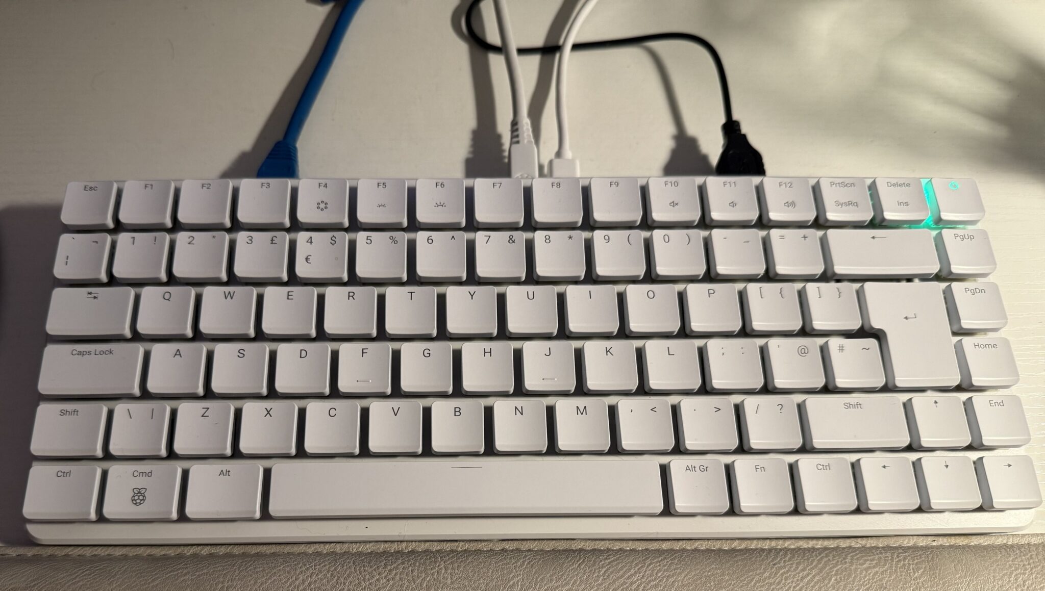
My RaspberryPi 500+ that I’m using to write this article
I ordered my 500+ from Pimoroni the moment the email saying it was available with its new high spec dropped into my inbox. Being one of the first to splash the cash I got a 20% discount off the price too, which made the purchase even easier.
A few days later the 500+ landed on my doorstep and I hastily unpacked it.
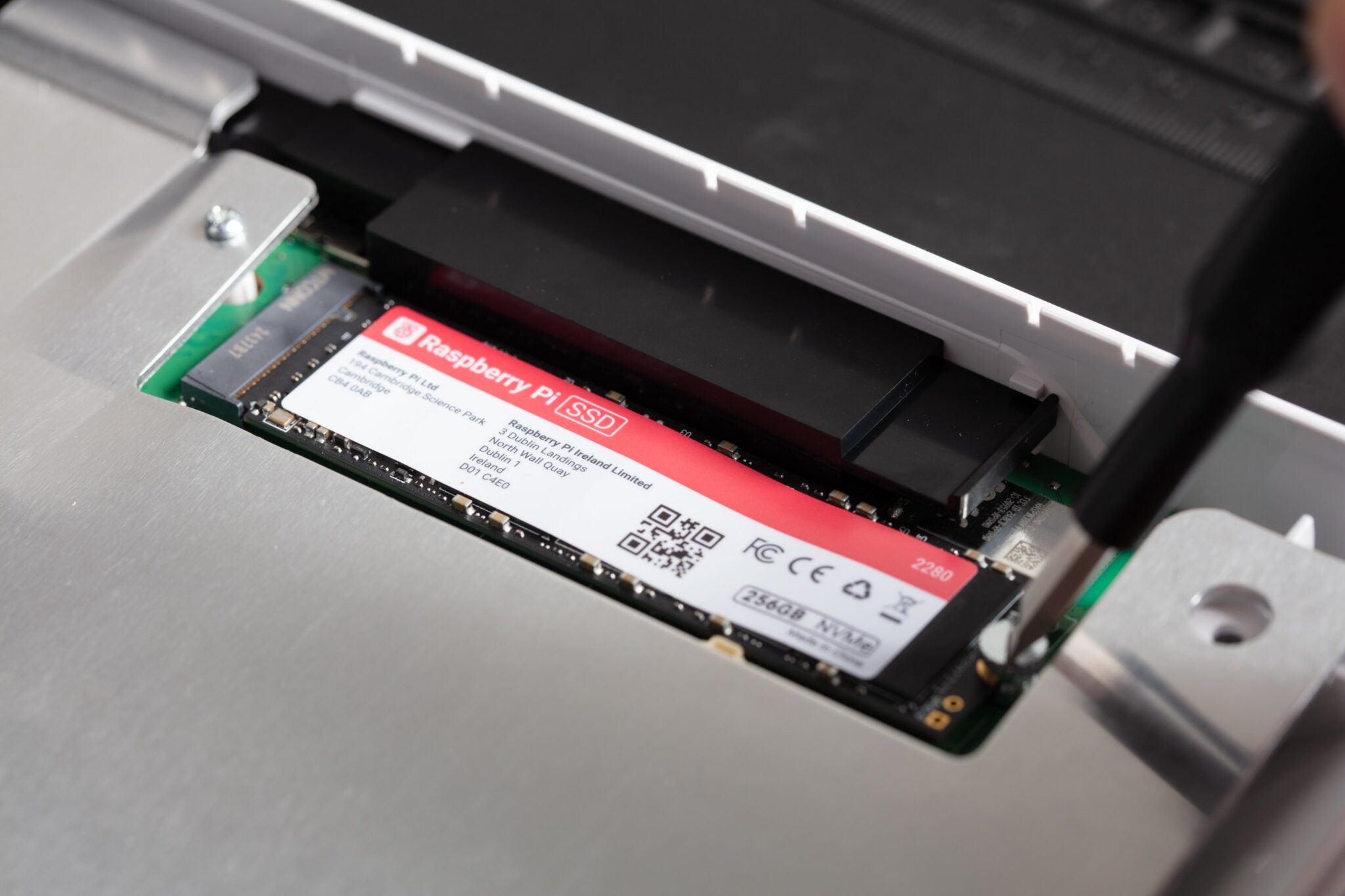
The 500+ comes with 16GB of RAM and a 256GB M.2 NVME SSD drive from the factory, exactly what we all wanted from the original 500. To everyone’s surprise the 500+ also comes with a new Clicky Gateron Blue KS-33 mechanical keyboard. This isn’t something I was expecting but, it was a nice surprise!
Connecting the 500+ to my mouse, ethernet cable, 4K monitor and official PSU it burst into life. The SSD comes preloaded with RaspberryPi OS and boots first time, no messing with loading ISO images to SD cards here!
The first thing I noticed was that the 500+ feels snappier than my Pi5, even though they both have the same SSD drive. Apps start just that bit quicker on the 500+ and copying files around feels quicker too.
Could this be because the SSD is now directly on the motherboard rather than at the end of a ribbon cable like on the Pi5?
The new keyboard is very different to use compared to the old 400/500 and the official RaspberryPi keyboard for the Pi SBC’s. It’s very clicky and slightly wider with more space between the keys. Initially this is annoying as it creates typo hell but, after some time your muscle memory adjusts and your typing gets back to it’s normal typo free experience.
The new keyboard is a nice improvement over the original 500 and makes the hiked price of £178.00 (with 20% discount) worth paying. The new keyboard is also backlit and can be adjusted to a range of colours and effects. I settled on having the keys light up in red once pressed as this is much easier on the eyes.
Since I’d been using a Pi5 with SSD as my desktop PC in the home office for over a year now I wanted to move my custom KDE-Plasma setup over to my new 500+ in place of the rather sparse RaspberryPi OS desktop that comes as standard on the 500+ SSD.
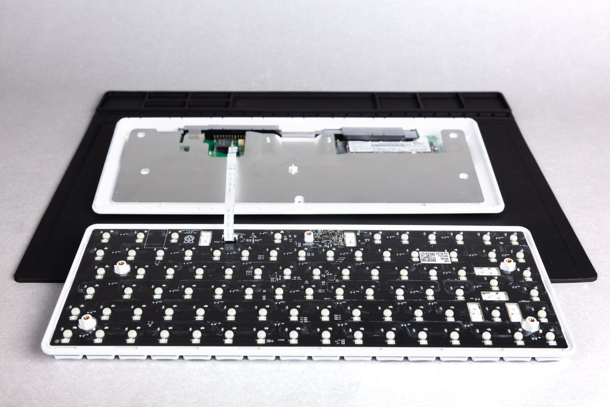
RaspberyPi 500+ open for SSD replacementRaspberryPi 500+ M.2 NVME SSD Drive
Opening the 500+ is relatively easy using the supplied spudger to tease the keyboard top and bottom apart once the screws have been removed.
Upon splitting the top and bottom sections you immediately become aware of the rather fragile looking ribbon cable that connects the keyboard to the motherboard. Access to the SSD drive is very good and it only took a minute to swap the drives over.
Gently clicking the keyboard back to the bottom half of the case and inserting all the screws I reconnected the computer to all my peripherals and switched it on.
In no time at all my favourite KDE-Plasma desktop and all my files and apps were at my fingertips just as they had been for the last year on my Pi5. An easy transition to the new 500+ now means I have a spare Pi5 and 250GB SSD for another project.
I must say that it would had been much nicer if there was a little removable panel on the bottom of the 500+ providing access to the SSD. This would had made it so much simpler to change the SSD drive without having to find the necessary tools to take the unit apart. Maybe an improvement for the 600+ next year!
The other thing I’ve noticed is that the 500+ runs considerably cooler than the Pi5 with the official cooler. My Pi5 would often reach 50 deg C however, the 500+ rarely gets above 30 deg C.
Overall I’m really pleased with my new RaspberryPi 500+, it’s the RaspberryPi I’ve been wanting in my home office for some time and finally it’s arrived.
Was it worth waiting for? Absolutely! It’s everything the 500 should had been at the outset.
I’ve been using my Xiegu XPA125b amplifier with my Hermes Lite 2 SDR transceiver for some time now and have found it to be a great performer. The only issue I have with the amplifier is that it is passively cooled with the operating temperature often reaching in excess of 50 degrees Celsius. There is an air vent on the right-hand side of the amplifier case and then a very small vent on the rear where the end of the PA heatsink is however, air flow is really poor and so the heatsink can get saturated with heat very easily.
Having recently purchased a Bambu Lab A1 Combo 3D printer I’d already decided I was going to have a go at designing and making a fan assisted cooling system for the Xiegu amplifier.
Having no experience and very little knowledge of 3D printing I dived in head first and hit the vertical learning curve head on. In a fairly short period of time I had put together a design that would work.
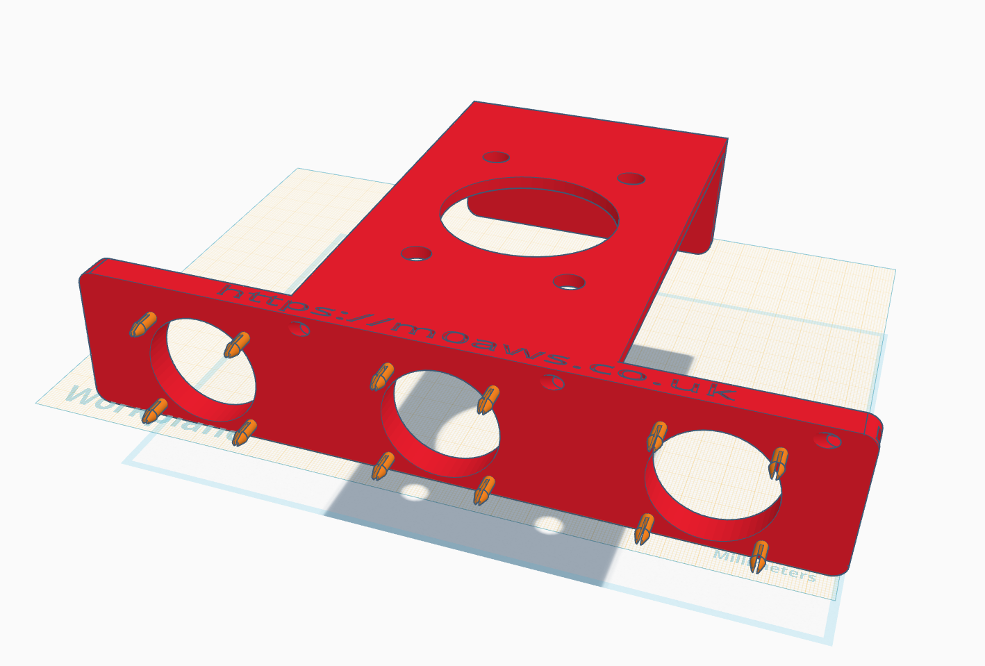
Designing the Xiegu XPA125b cooling system using TinkerCAD.
After 11 design versions and 3 x 3D prints I had a solution that fitted perfectly every time. Getting the 12v fans from Amazon was fairly cheap and I soon had the amp cooler working with a temperature reduction of 20-25 degrees Celsius during long waffle overs on the 80/60m bands. The amp now runs nice and cool with great airflow through the heatsink.
Next I wanted to add a Hermes Lite 2 cradle to the cooler solution so that two devices are neatly stacked together. Like the cooler design, I already had ideas in my head and just needed to get them down in the CAD package.
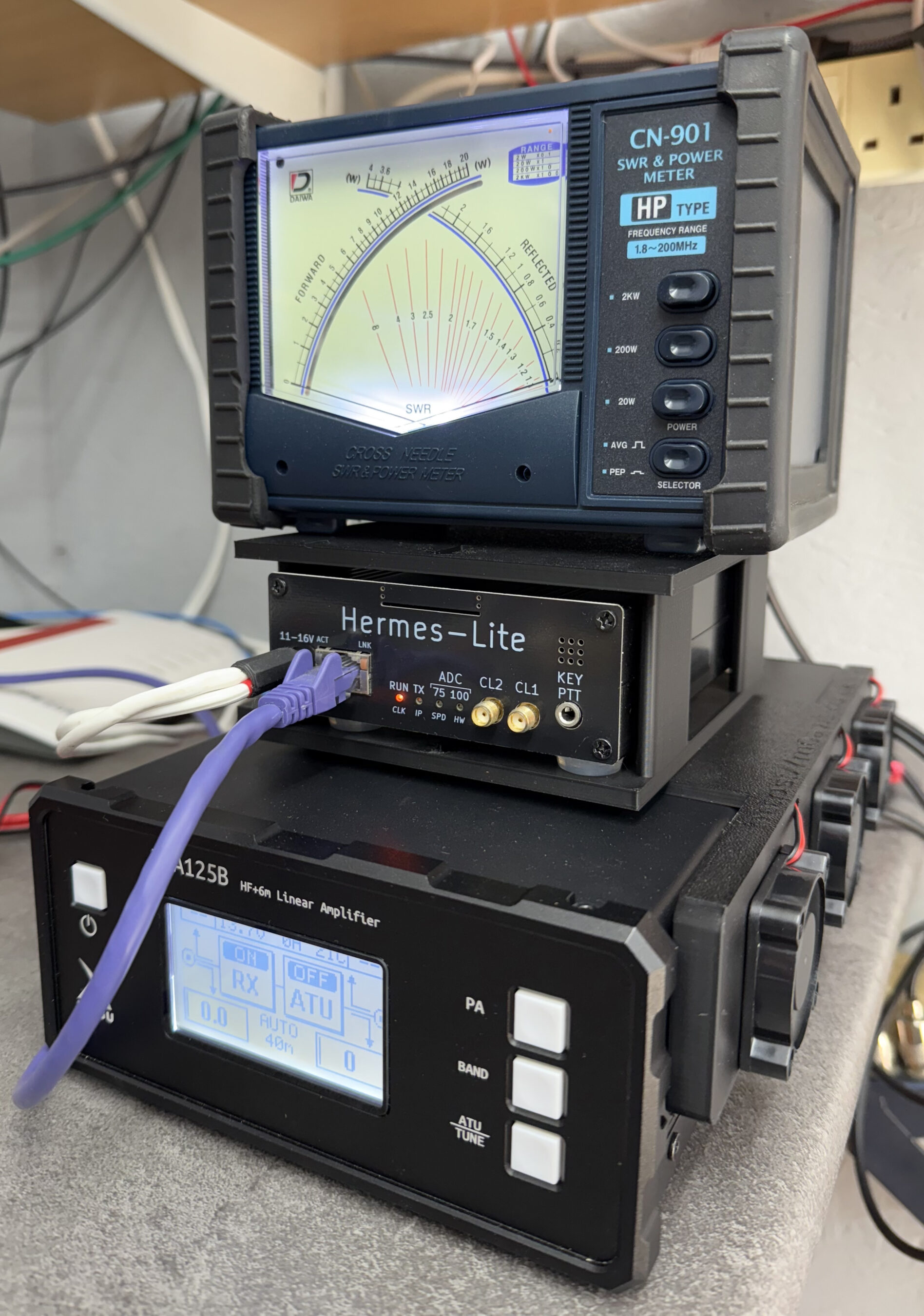
After some tinkering and 3 test prints I had a solution designed that not only created a cradle for the Hermes Lite 2 but, also a top shelf for my Daiwa CN901HP to sit on.
This brought the whole HF transceiver setup together nicely with all the components now being held in place securely.
Xiegu XPA125b Cooler with Hermes Lite 2 cradle – front viewXiegu XPA125b Cooler with Hermes Lite 2 cradle – side view
The 3 fans on the side of the amp are silent which is great, there is a little noise from the air flowing through the case and out the vent at the back of the unit however, it’s barely noticeable. Keeping the case pressurized with cool air and forcing the heat out the rear vent has made a massive difference to the overall temperature of the amp even during long hours on air.
This has been a fun project and a great introduction to 3D printing, I’ve got so many more 3D print ideas now, I think I’ll be spending a lot of time in TinkerCAD.
I’ve just printed and put together a cooler and HL2 cradle for Steve, M0XVT and will be making them to order soon so, if you have a Xiegu XPA125b and want it to run a lot cooler then keep an eye on my website for details of how to buy one.
For some time I’ve been considering purchasing a 3D printer so that I can create parts for my HAM Radio projects. The issue has always been, what printer to buy?
Having searched online, watched many YouTube videos and endless reading I ended up even more confused and no closer to making a decision. In the end I decided to step away from the idea for a while and see where things went.
Some time much later I ventured back to the subject and discovered the Bambu Lab 3D printer range. These were getting rave reviews and were positioned as being ideal for the total 3D printing beginner.
Once again I read as much as I could about the Bambu Lab printers, watched endless videos and searched online for supplies, spare parts etc to ensure they were readily available.
Eventually I had all the boxes ticked.
Relatively easy to use software
MacOS/Linux supported
Can print using the filament types I need for my projects
Good size print plate
iPhone App
Wireless connectivity
Built in camera for time-lapse videos
Multi-colour filament delivery system
Sensibly priced filament
Readily available replacement parts
Active Eco System and community
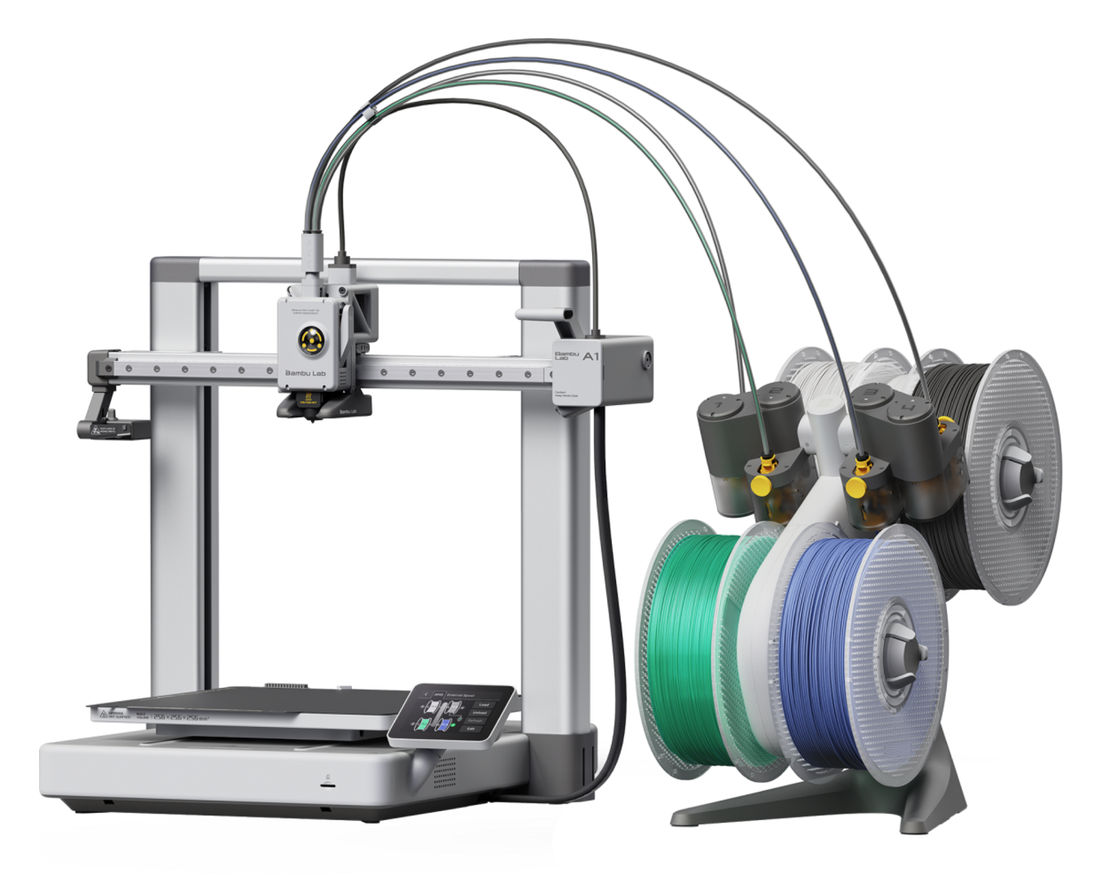
Looking at all the current 3D printers available in the Bambu Lab range I decided to purchase the A1 Combo model. This has a 256 x 256mm build plate, 4 filament feed print head and the filament Automatic Management System (AMS) that makes multi-colour printing a breeze.
With the decision made all I had to do was find a supplier. Strangely enough buying direct from Bambu Lab gave the best price and with the £10 voucher and 28% off of filament bought at the same time as the printer it was a no brainer.
£528 later I had 10 rolls of filament and an A1 Combo 3D printer winging it’s way to me.
Bambu Lab A1 Combo 3D Printer
2 days later our local DPD delivery driver arrived with 2 large boxes and a comment about how heavy one of the boxes was.
Upon opening the printer box I found it was extremely well packed. The printer comes in a partially assembled form and requires some assembly by the end user. All the parts are really well labelled right down to each packet of screws being labelled with their exact use. All the tools needed to assemble the printer are included as is the easy to follow manual.
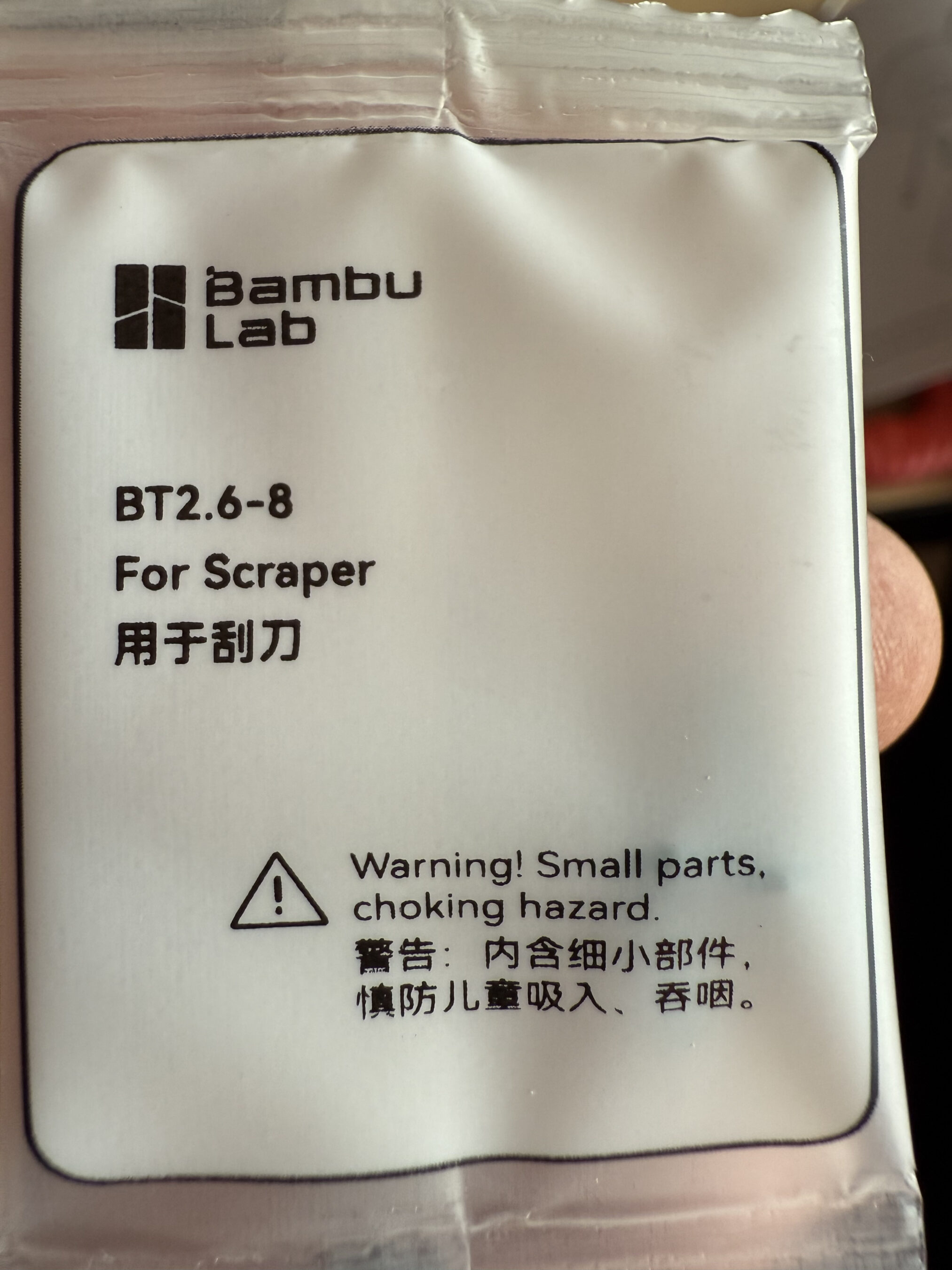
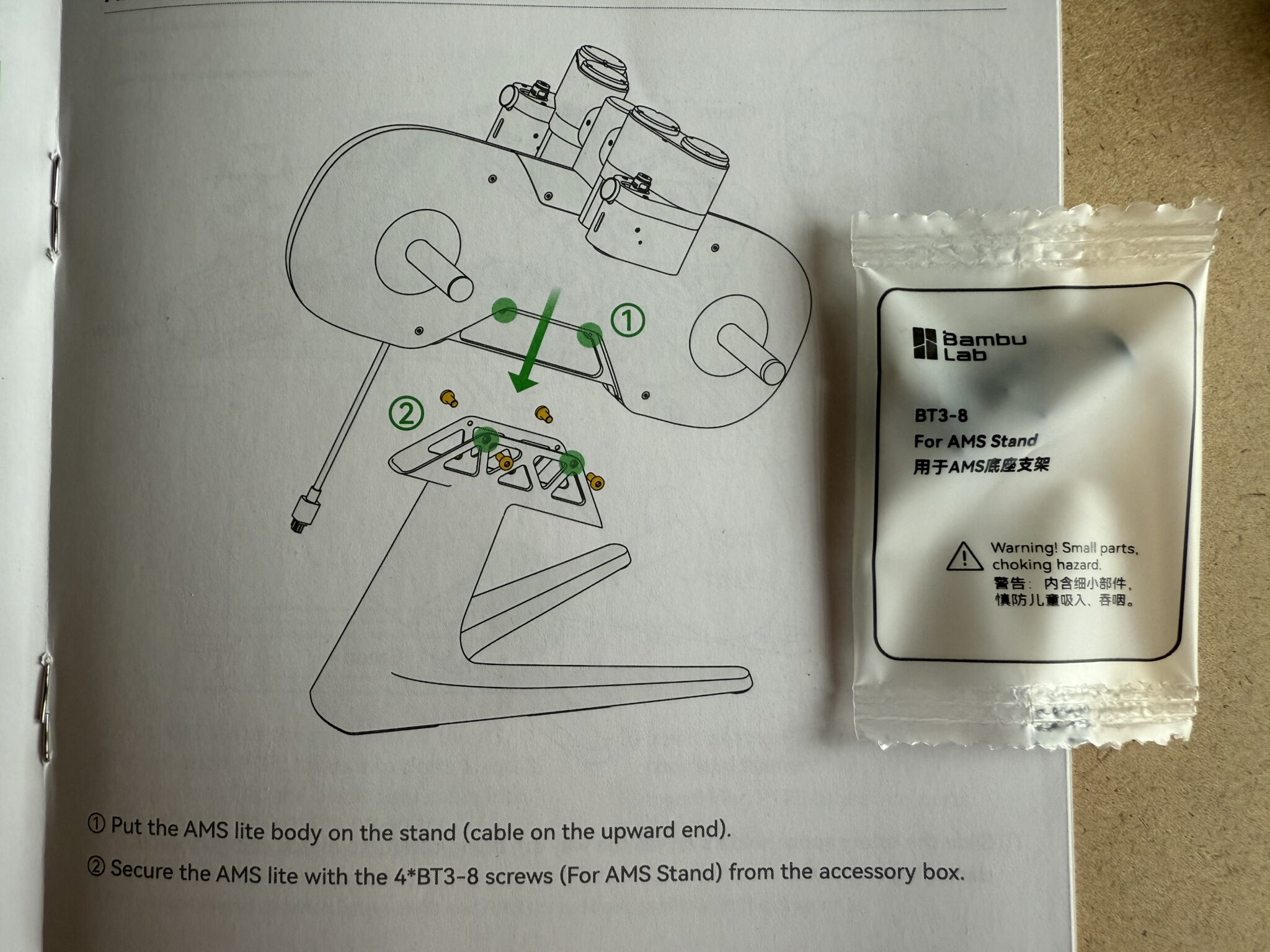
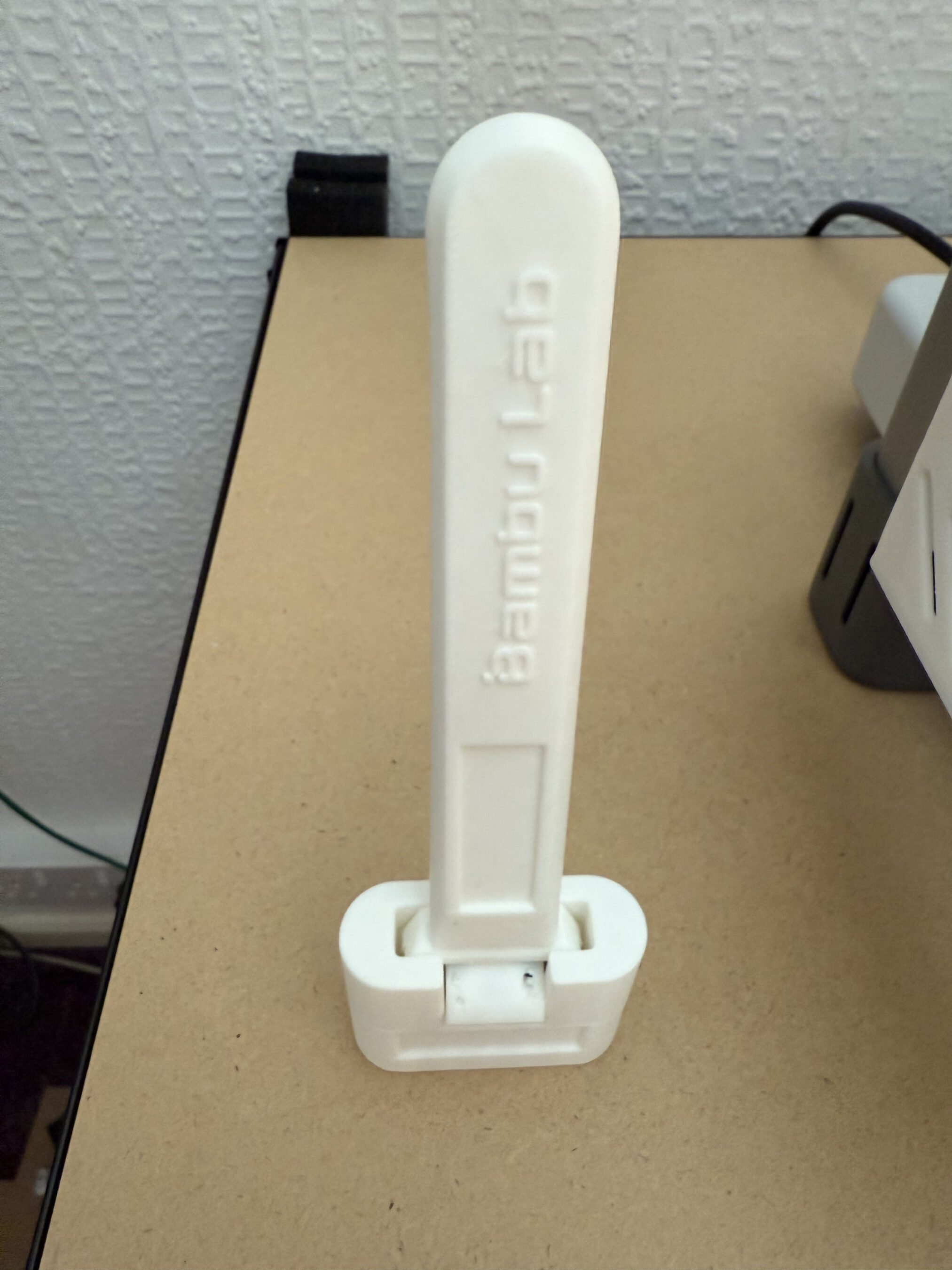
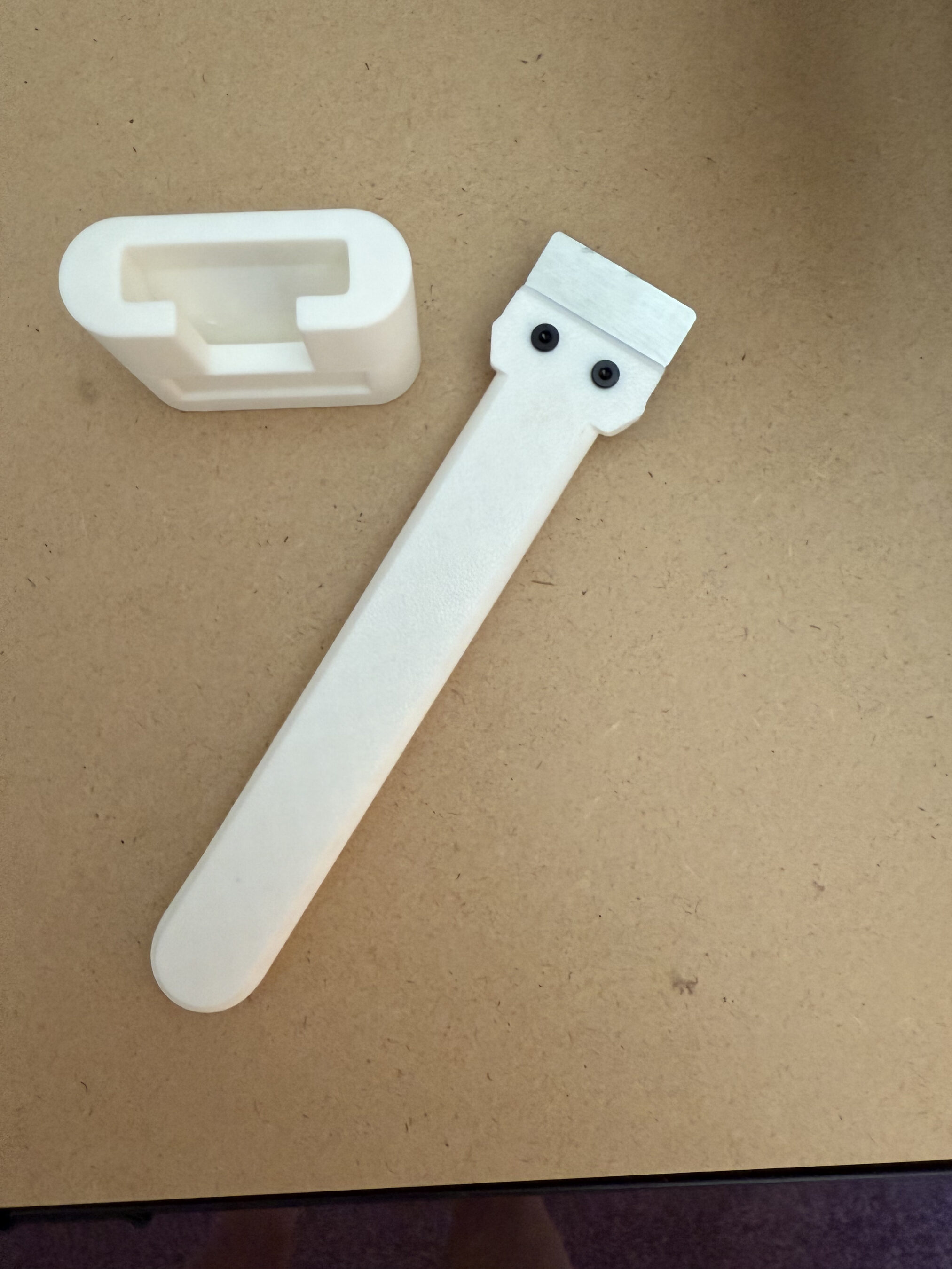
Bambu Lab screw packages labelled for each partBambu Lab screw set for the AMS Stand
Another thing I really liked about Bambu Lab is that they supply you with screws for things that aren’t in the box, like the scraper screws shown above. At first I thought this was a bit weird but, in reality this makes complete sense as printing your own tool set is a great introduction to making your first prints.
Next I attacked the heavy box, this contained the 10 reels of filament I’d purchased at the same time. I’d ordered a good assortment of colours that would keep everyone in the family happy.
Installing the BambuStudio software on my MacBook Pro was a breeze. Using the account I setup at purchase time I was soon hooked into the Bambu Lab Makerworld community.
I immediately found the tools I needed to print and set about making my first 3D prints. The software has a lot of functionality, especially when it comes to the designing of your own objects. It’s fair to say the initial learning curve is vertical however, there are some great videos on YouTube on printing downloaded objects using the BambuStudio software.
ambuLab Scraper and Stand 3D PrintBambuLab Scraper and Stand 3D Print
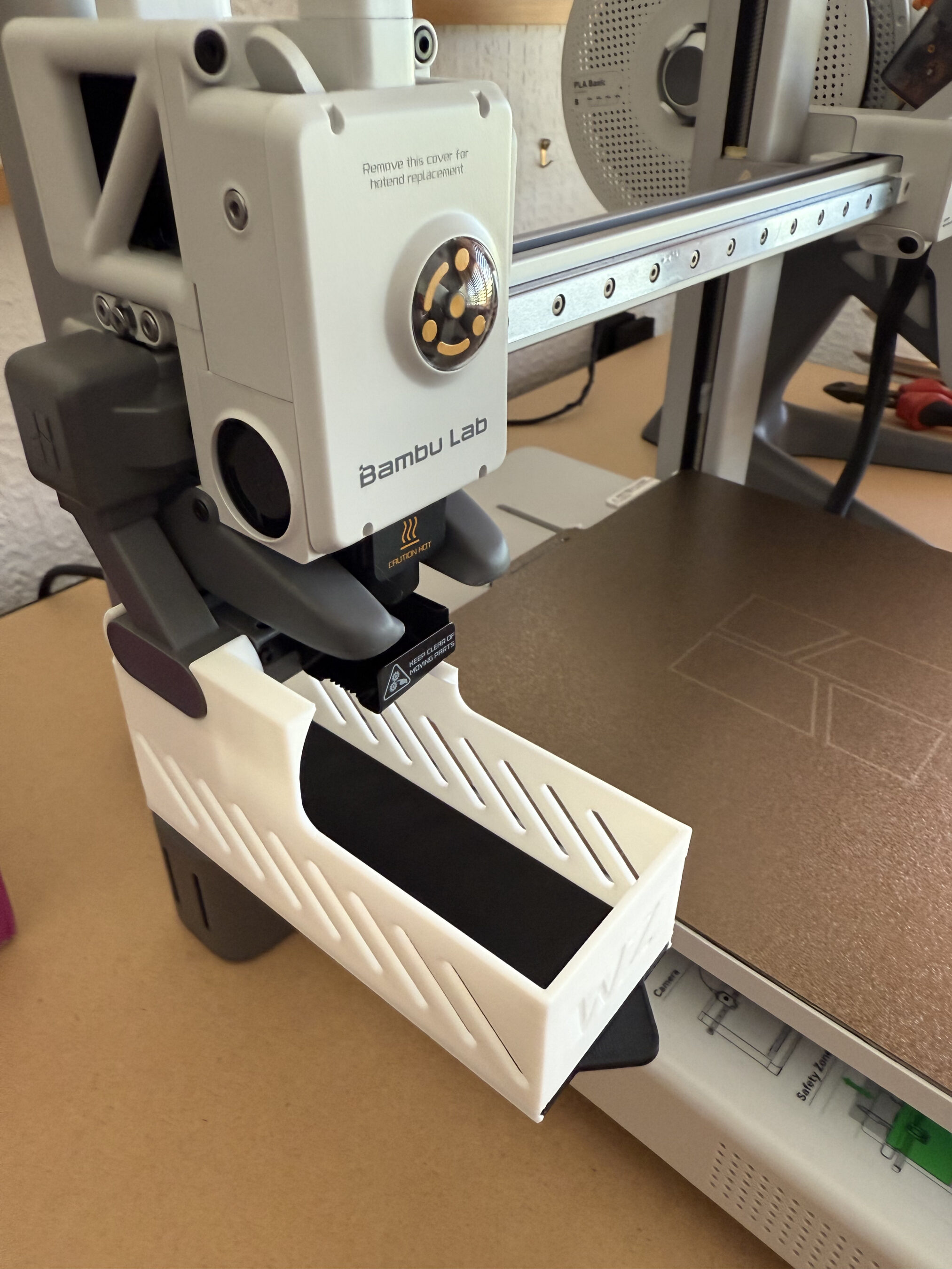
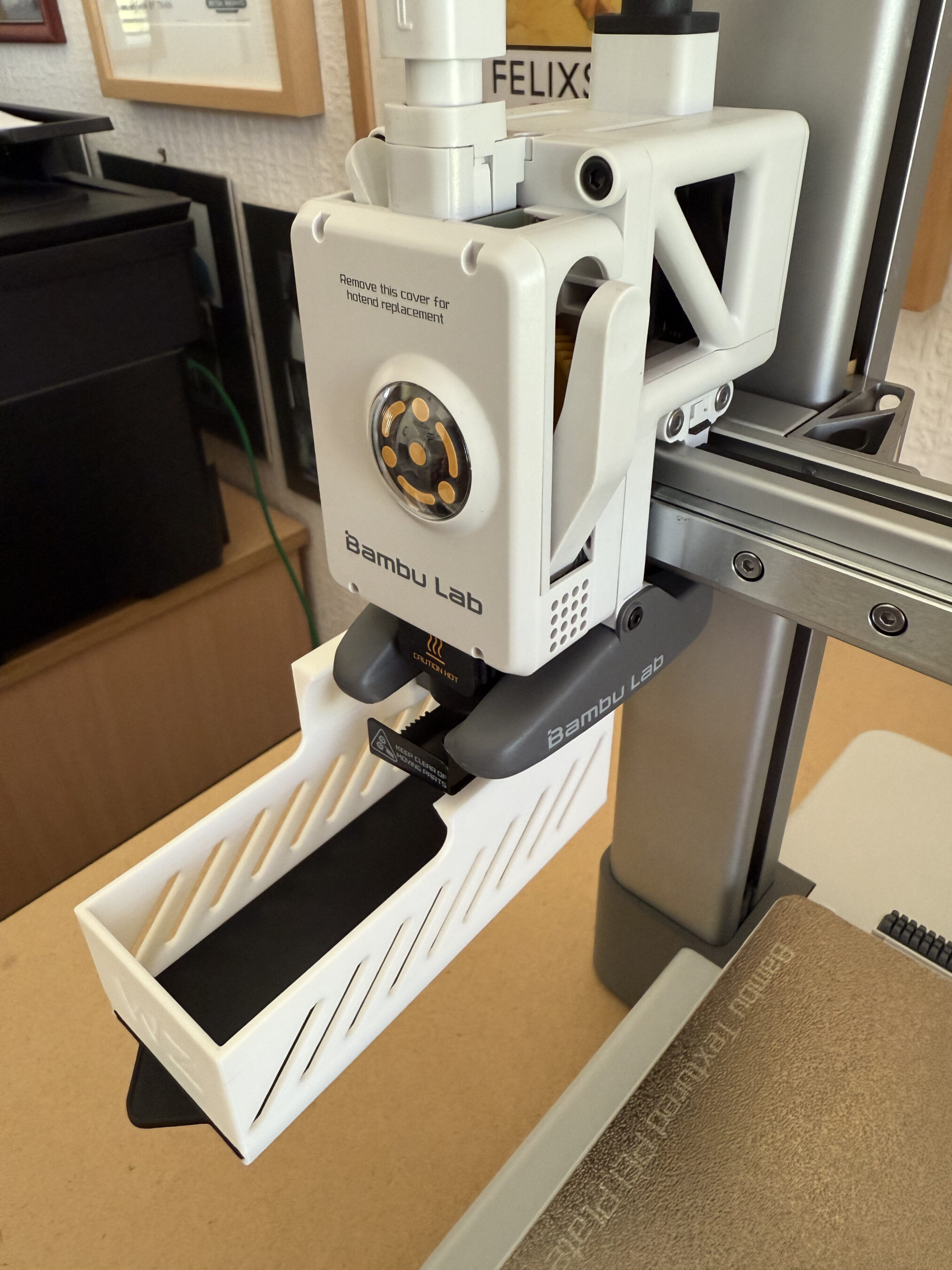
Whilst searching for 3D Print tools on the MakerWorld I stumbled across this really neat filament waste collector that fits nicely onto the X axis support. During the print there is a small amount of waste filament, especially if you are printing a multi-colour object as the print head has to be purged each time a new colour is required. Out the box there is nothing to catch the waste filament and so, it ends up on the floor. Fortunately the MakerWorld community resolved this issue with a multitude of options for collecting and storing the waste, all of which you can print yourself.
3D printed waste filament collection bin3D printed waste filament collection bin
The print speed is incredibly quick, much quicker than I ever imagined and it’s addictive to stand and watch the print take form right in front of your eyes.
Printing an iPhone Stand for my sister-in-law
Once I’d printed the necessary tools and a few downloaded iPhone stands for the family I set about looking at designing my own objects.
The Bambu Studio software does have the capability to design objects built in but, the learning curve is vertical and there are very few videos on YouTube showing how to use the object creation section of the software. This lead me to look for an alternative 3D CAD package that had tutorials on how to create 3D print objects. After a little searching online i found that Tinkercad has a great range of tutorials online to get people started with designing their own 3D print objects.
In no time at all I had an account created on the tinkercad site and was going through the online tutorials to learn how to use all the functionality offered in the free tier.
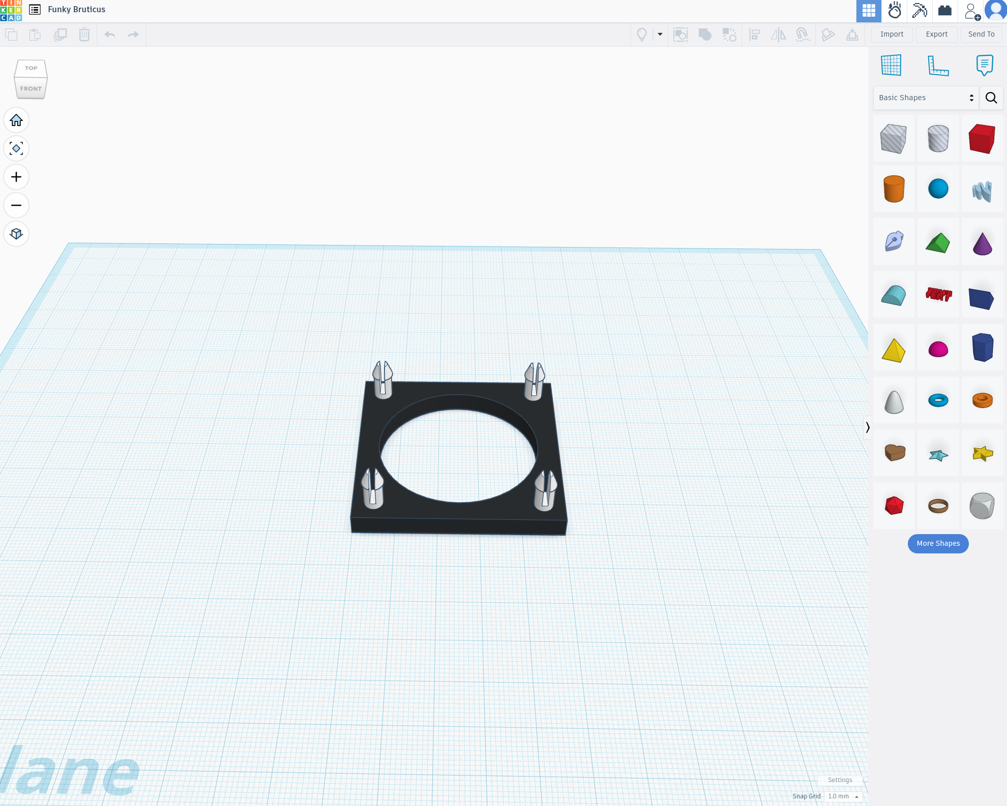
TinkerCAD – Designing a cooling fan mount
The online tutorials are very good and move along at a good pace with interactive examples that show you how things work. Once I’d completed the tutorials I dived straight into designing some objects of my own.
I’ve still got a lot to learn about 3D printing but, I have to say that TinkerCAD really does simplify the whole design process. Once my object designs were complete, all I had to do was export them in .stl format and then import the STL file into Bambu Studio and send it to the printer.
So far my prints have come out great and I’ve been really impressed with the quality of the finished articles.
I’ve now started on my list of HAM Radio 3D print projects and will document my progress over the next few weeks and months as I progress.
More soon …
We use cookies to ensure that we give you the best experience on our website. If you continue to use this site we will assume that you are happy with it.