A quick chat with Callum – DXCommander on 80m

Using just 20w I had a quick chat with Callum of DXCommander fame on the 80m band using my Inverted-L antenna.

Very happy with the signal report and being able to hear myself after the event was very interesting. I’ve not used my Yaesu FTDX10 much on SSB and so I was very happy to hear that the audio sounded nice and clear.

More soon …

Modelling my Inverted-L Antenna

Since I put together my Inverted-L antenna and Pi-Network ATU I’ve been having a lot of fun on the low bands.

Getting back onto 160m has been most enjoyable and I’ve now had over 100 ‘Top Band’ contacts with distances covered as far as 3453 Miles into Sosnovoborsk Asiatic Russia.

I must admit I am amazed at the distances achieved on the 160m band as the antenna isn’t very high above ground level when compared to a single wave length on 160m.

M0AWS Inverted-L Antenna View

The Inverted-L antenna at the M0AWS QTH was designed purely around the size of the back garden. Using a couple of 10m Spiderpoles the vertical section of the antenna is 10m tall and the horizontal section is 28m long. Naturally the antenna resonates around 2.53Mhz but, can be tuned to resonate anywhere on any band using the Pi-Network ATU I built that is situated at the base of the vertical section of the antenna.

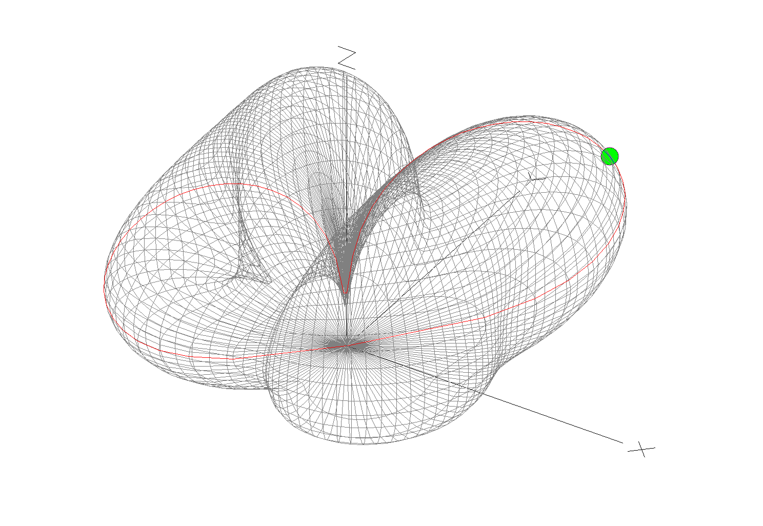
Looking at the far field plots for the antenna on each band we see that as we move higher in frequency the radiation pattern becomes more complex and the radiation angle gets lower, exactly what we would expect from such an antenna. The antenna runs pretty much North/South in the garden ( X axis on the diagram above) and so we would expect the antenna to radiate East/West (Y axis on the diagram above) however, this isn’t always the case.

(Click Far Field Plots for full screen view)

On 160m the antenna favours the South (-X Axis) and presents some usable high angle gain although, from using the antenna you would never know this to be the case as it seems to have pretty good all round coverage. With the best distance of 3453 Miles being covered to the East into Asiatic Russia the antenna performs well even though the far field plot is slightly biased to the South.

On the 80m band the Inverted-L antenna becomes a cloud warmer and exhibits very high angle radiation. On 80m the antenna is ideal for NVIS Inter-G propagation and is great for rag chewing with other UK/Near EU stations.

Looking at the far field plots for the 60m band once again the antenna provides lots of high angle gain however, there is also some very useable lower angle gain that has proven to be excellent for working long hauls into North America and east into Central Asia. On the 60m band during the day the antenna is excellent for Inter-G chatting, using just 20w-40w I can very easily chat with other UK HAMs even when the band is noisy.

Moving on up to the 40m band we find the far field plot starts to get a little more complex. Looking at the 3D plot you’d think that the antenna favoured the South (-X Axis) however, in reality it favours the NorthWest with both some high and low angle gain. This antenna has proven to be excellent for DXing into North America on 40m but, has also been great for DXing into South America getting great signal reports from stations in Panama at a distance of 5415 Miles. During the day NVIS propagation is excellent and I find I can chat with other UK and near EU stations with ease using just 25w.

M0AWS Inverted-L Antenna 60m/40m Global Coverage

Above is a screen shot from PSKReporter showing stations that have heard me on the 40m and 60m bands. As you can see, global coverage is excellent with stations as far as Australia and New Zealand hearing me on the 40m band and stations on the West Coast USA hearing me on the 60m band. I was also pleased to see I was heard in Africa on both bands, a region of the world I would like to get more contacts from.

On the 30m band the Inverted-L antenna starts to exhibit two lobes with gain to the NorthEast and NorthWest. This makes the antenna ideal for working into the USA and Australia/New Zealand over the North Pole. Working US stations is a breeze with relatively low power and I almost got a contact with New Zealand during the evening greyline but, unfortunately the DX station dropped out before I managed to get my signal report back to him. As time goes on I’m sure the antenna will more than prove itself on the 30m band.

So far I’ve not ventured above the 30m band with the Inverted-L antenna as I’ve really been enjoying access to Inter-G chats on 80m, 40m and 60m and chasing DX on 160m, 60m, 40m and 30m. I need to venture up onto the higher bands before the long winter nights settle in and the higher HF bands close for the winter season.

Looking at the far field plots on the higher HF bands the antenna has huge potential as it provides some nice low angle radiation in useful directions.

On the 20m band the far field plot starts to get much more complex with lobes at many different angles. The main gain lobe is to the NorthEast towards the USA and is at a fairly low angle and so this antenna should be great for working stateside on the 20m band. There are also lobes to the NorthEast and so hopefully working VK/ZL over the pole should also be possible. As I said above I’ve not yet used the antenna above the 30m band and so at this time cannot confirm performance but, it looks promising.

The 17m band also looks promising with a similar far field plot as the 20m band but, with lower angle of maximum radiation and more gain. It will be very interesting to test this antenna on 17m especially since the noise level is below S0 and I can very easily hear the weakest of stations on this band.

Once again the 15m band looks very similar to the 17m band, low angle radiation but, with a slightly more complex far field plot.

The 12m band far field plots continue the theme with the angle of maximum radiation slightly lower than on the 15m band and slightly more gain. This antenna should be great for chasing the DX on the very quiet 12m band.

Finally the 10m band is very similar to the 12m band in that the far field plots show low angle gain albeit with an even more complex radiation pattern.

I originally put this antenna up so that I could work Inter-G on the low bands but, it has proven to be a much more worthy antenna than I originally thought it would be. I need to spend more time with this antenna on the bands above 30m to really see how it performs on the higher HF bands but, so far I’m really pleased with it’s overall performance on all the bands tested to date.

I can highly recommend using FT8 to test new antennas. With PSKReporter and my own NodeRed World Map WSJT-X interface I can see realtime the antenna performance on each band. FT8 is an extremely useful tool when it comes to testing antennas to see if they perform as per the modelling and can often provide some performance surprises!

More soon …

Making my 160m Inverted-L into a Multi band Antenna

I recently put up a 38m Inverted-L antenna (10m vertical/28m horizontal) and tuned it on the 160m band using a home-brew Pi-Network ATU. It’s working great on top band and I’m really pleased with performance so far.

I decided today that it would be good to try the inverted-L out on some of the other low bands too. Since my other HF antenna is a large vertical that’s great for DXing but, terrible for Inter-G I thought perhaps the Inverted-L would fill the inter-G gap.

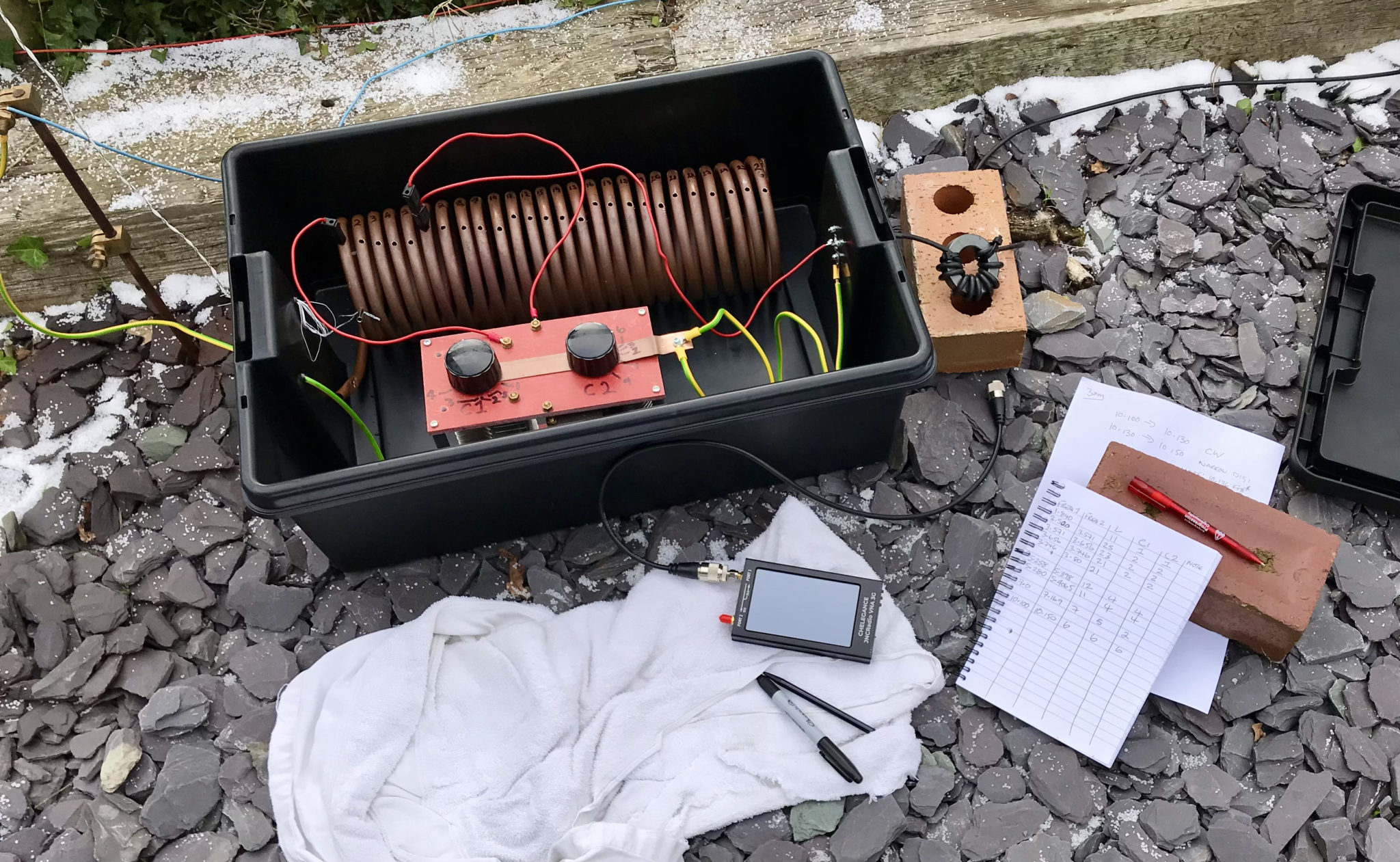
M0AWS Pi-Network ATU using my JNCRadio VNA to find the ATU setting for each band

Having recently purchased a JNCRadio VNA from Martin Lynch and Sons it made tuning the ATU for each band really easy. When it comes to antenna resonance I like my antennas to have an SWR of less than 1.2:1. With the VNA connected it is really easy to tune the antenna for a 1:1 SWR on a particular frequency, make a note of the tune information and then move to the next frequency and start again.

I marked up each turn on the large copper inductor so I could record the position of the input wire onto the inductor. I then added some markings on the two capacitors of the Pi-Network ATU for the resonance points on each band/frequency I wanted to resonate the antenna on.

M0AWS Pi-Network ATU settings noted for each band

After about 40mins I had all the settings recorded on a pad ready for testing from the shack end of the coax run. Connecting my Yaesu FTDX10 to the coax I ran through each band setting checking the SWR as I went. All bands tuned up perfectly 160m through 30m and receiving of Inter-G on the bands that were active was excellent.

Wanting to test the antenna on 40m for the first time I found Nick, M7NHC calling CQ and gave him a call using just 5w output. He came straight back to me and we had a quick chat.

Nick was using an Icom IC-7300 using just 10w into an end-fed long wire from Eastbourne down on the south coast so, we were both QRP. Nick was a 5/7 with QSB and he gave me a 5/8 with QSB, not bad at all consider how much power we were using.

I’m hoping to have a chat with some of the guys from the Matrix this evening on 60m SSB so, it will be interesting to see how the antenna performs on 5Mhz.

More soon …

20m Band Delta Loop Antenna

I’ve had this antenna model for ages now but, never got round to putting it onto the website until Alex, GM5ALX was talking about making one the other day whilst chatting on the QO-100 satellite.

The 20m band delta loop follows exactly the same design principles as all the other delta loop designs I’ve already put on the website. They are designed such that they present a 50 ohm impedance at the feed point and thus have no requirement for complex impedance matching circuits/transformers.

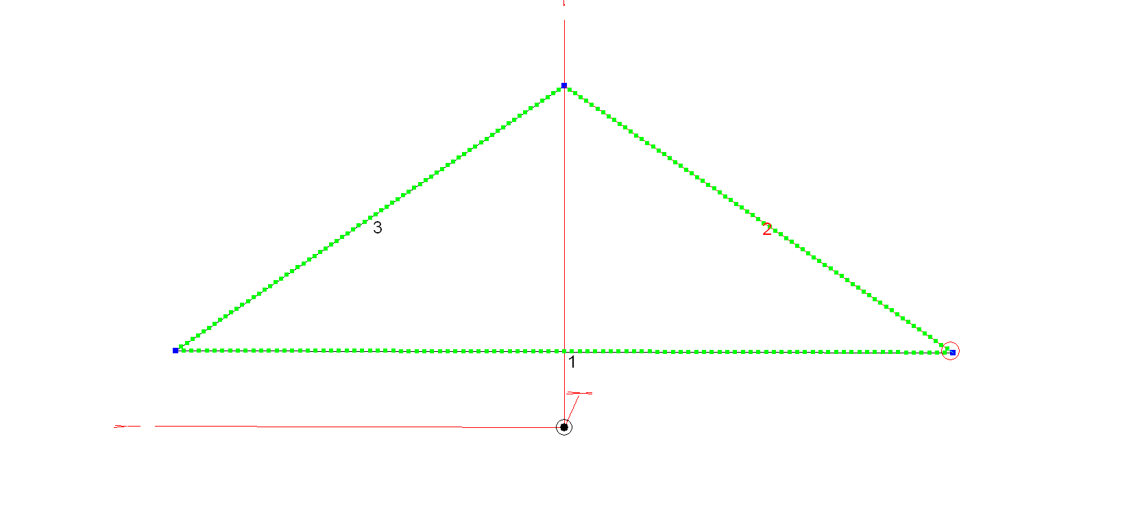
M0AWS 20m Band Delta Loop Antenna - Antenna View
M0AWS 20m Band Delta Loop Antenna – Antenna View

The dimensions for the antenna are as follows:

Wire 1 – Horizontal exactly 1m above the ground for its entire 10.2m length.
Wires 2 & 3 are exactly 6.18m long each with the top being 4.5m above the ground.

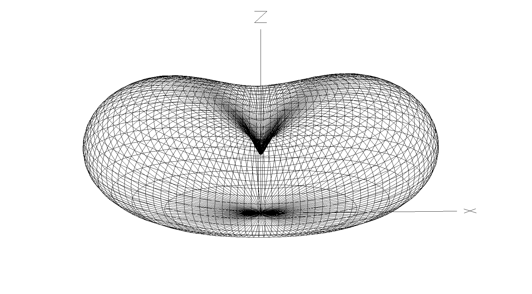
M0AWS 20m Band Delta Loop Antenna - 3D Far Field Plot
M0AWS 20m Band Delta Loop Antenna – 3D Far Field Plot

The 3D far field plot shows a typical delta loop radiation pattern with the maximum radiation through the loop and a deep null in the centre.

M0AWS 20m Band Delta Loop Antenna - 2D Far Field Plot
M0AWS 20m Band Delta Loop Antenna – 2D Far Field Plot

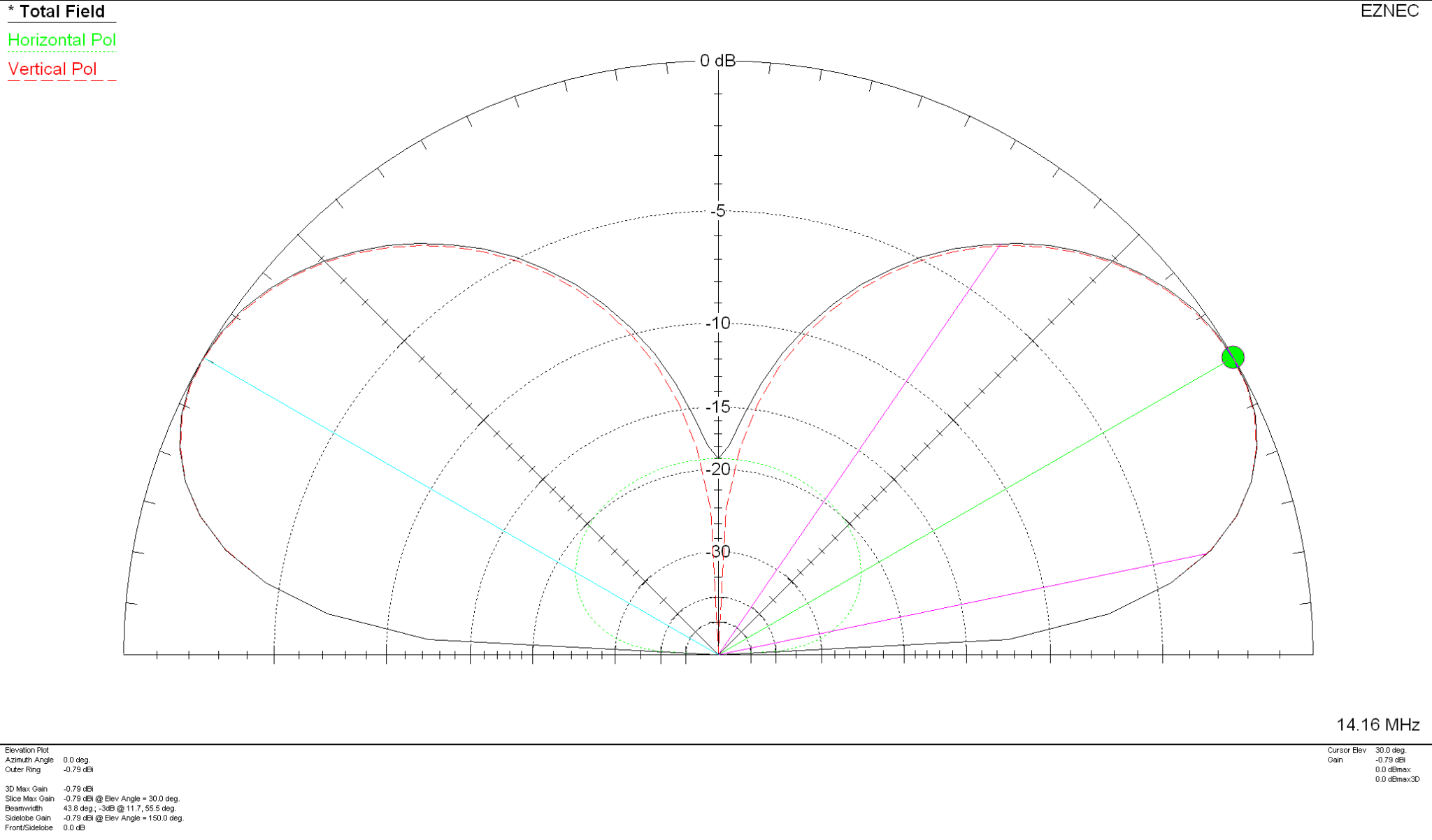
The 2D elevation plot shows that the antenna will give a maximum gain of -0.79dBi at 30 degrees when used over average/poor soil types. If like me you use your Delta Loop antennas on the beach then the antenna will present considerably more gain as it will benefit from the salt water reflection.

If you want to lower the angle of maximum radiation and increase the gain over average ground just raise the antenna up so that the top is around 7m above ground. This will give a much lower angle of radiation and improve the gain figure by 2-3dBi. Don’t forget that if you raise the antenna the point of resonance will also rise in frequency and so you may need to shorten the wires a little to get the point of resonance back to where you want it.

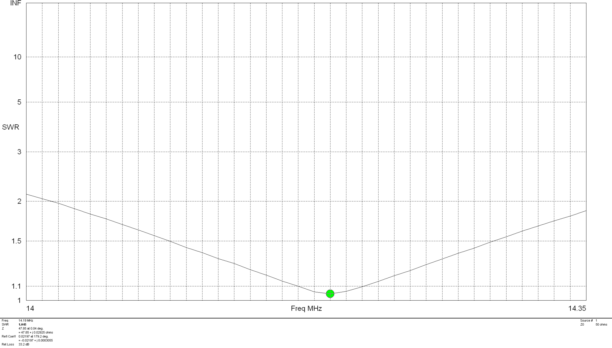
The SWR plot shows that the antenna will have a fairly wide bandwidth and match to 50 ohm coax extremely well. The antenna is designed to be fed in one of the lower corners via a 1:1 balun for best results.

M0AWS 20m Band Delta Loop Antenna - SWR Curve
M0AWS 20m Band Delta Loop Antenna – SWR Curve

Summary:

Total Wire Length: 22.56m
Horizontal Wire Length: 10.2m @ 1m above ground
Diagonal Wire Lengths: 6.18m
Wire Dia: 2.5mm
Height at Centre: 4.5m
Feed Type: 1:1 Balun in bottom corner (Can use coax if necessary)
Impedance: 50 Ohm
SWR: <1.5:1 at resonance

Getting back onto 160m “Top Band”

Since setting up the new HAM station here in the UK the one band I’ve not yet got back onto is 160m, one of my most favourite bands in the HF spectrum and one that I was addicted to when I live in France (F5VKM).

Having such a small garden here in the UK there is no way I can get any type of guyed vertical for 160m erected and so I needed to come up with some sort of compromise antenna for the band.

Only being interested in the FT4/8 and CW sections of the 160m band I calculated that I could get an inverted-L antenna up that would be reasonably close to resonant. It would require some additional inductance to get the electrical length required and some impedance matching to provide a 50 Ohm impedance to the transceiver.

Measuring the garden I found I could get a 28m horizontal section in place and a 10m vertical section using one of my 10m spiderpoles. This would give me a total of 38m of wire that would get me fairly close to the quarter wave length.

For impedance matching I decided to make a Pi-Network ATU. I’ve made these in the past and found them to be excellent at matching a very wide range of impedances to 50 Ohm.

M0AWS Homebrew Pi-Network ATU

Since I still had the components of the Pi-Network ATU that I built when I lived in France I decided to reuse them as it saved a lot of work. The inductor was made from some copper tubing I had left over after doing all the plumbing in the house in France and so it got repurposed and formed into a very large inductor. The 2 x capacitors I also built many years ago and fortunately I’d kept locked away as they are very expensive to purchase today and a lot of work to make.

Getting the Inverted-L antenna up was easy enough and I soon had it connected to the Pi-Network ATU. I ran a few radials out around the garden to give it something to tune against and wound a 1:1 choke balun at the end of the coax run to stop any common mode currents that may have appeared on the coax braid.

Connecting my JNCRadio VNA I found that the Inverted-L was naturally resonant at 2.53Mhz, not too far off the 1.84Mhz that I needed. Adding a little extra inductance and capacitance via the ATU I soon had the antenna resonant where I wanted it at the bottom of the 160m band.

M0AWS 160m Inverted L Antenna SWR Curve

With the SWR being <1.5:1 across the CW and FT8 section of the band I was ready to get on 160m for the first time in a long.

Since it’s still summer in the UK I wasn’t expecting to find the band in very good shape but, was pleasantly surprised. Switching the radio on before full sunset I was hearing stations all around Europe with ease. In no time at all I was working stations and getting good reports using just 22w of FT8. FT8 is such a good mode for testing new antennas.

As the sky got darker the distance achieved got greater and over time I was able to work into Russia with the longest distance recorded being 2445 Miles, R9LE in Tyumen Asiatic Russia.

In no time at all I’d worked 32 stations taking my total 160m QSOs from 16 to 48. I can’t wait for the long, dark winter nights to see how well this antenna really performs.

M0AWS Map showing stations worked on 160m using Inverted L Antenna

The map above shows the locations of the stations worked on the first evening using the 160m Inverted-L antenna. As the year moves on and we slowly progress into winter it will be fun to start chasing the DX again on the 160m band..

UPDATE 6th October 2023.
Been using the antenna for some time now with over 100 contacts on 160m. Best 160m DX so far is RV0AR in Sosnovoborsk Asiatic Russia, 3453 Miles using just 22w. Pretty impressive for such a low antenna on Top Band.

More soon …

My old valve radio station

Going through some old photos today I found a few great memories from the past of my old valve radio stations that I’d restored over the years.

These old radios gave me some wonderful moments over the years and a fair few hours of restoration to get them into operational condition. They sounded great on air and I often got comments from other amateur stations about how warm the audio sounded. Some did also mention the drift of the transmitter with temperature changes but, you just have to accept that when using vintage radio equipment.

M0AWS FT101E Transceiver, FL101 Transmitter, FR101B Receiver and TS520S Transceiver.

Above is my old FT101 line up. It consisted of the great FT101E transceiver, a complete standalone solution that was extremely popular in its day. Below it is the FT101 line up made up of the FT101 transmitter, FR101B receiver and matching speaker.

Top right is the lovely Trio TS520S with the matching digital frequency display which is incredibly rare and very sought after today.

These radios gave me a lot of pleasure for many years and I wish I still had them today.

My second Yaesu valve line up took a lot more restoration than the 101 series and was quite challenging at times but, with a lot patience and time spent sourcing parts I got them back to as close to new operational condition as was possible.

M0AWS FLDX400 Transmitter, FRDX400 Receiver, FL2000B Amplifier and FTDX501 Transceiver.

The Yaesu 400 series line up consisted of the FLDX400 transmitter, FRDX400 receiver and was finished off with the FL2000B amplifier. These 3 pieces of radio equipment looked beautiful in the flesh and were wonderful to operate. Taking a good 15mins to warm up and become stable you couldn’t rush getting on air. This line up was my favourite by far even though they weren’t as good as the 101 line up.

Above the 400 series is the later FTDX501 transceiver with matching speaker. This was a great radio in its own right but, not as much fun to operate as the 400 line up. To the right of the FTDX501 is the matching Yaesu Microphone for the 400/500 series. This mic is incredibly rare and I had to visit many radio swap rallies to find it, worth the effort though.

Top right you can see my old SWL receiver, the great Drake SW4A. I never had a Drake line up as they are quite rare in the UK but, it certainly would had made a great addition to the station.

M0AWS FLDX400, FRDX400 & FL2000B Station being operated by M1ACB and G6ALB

Finally this is a photo of two friends of mine, Steve Thomas M1ACB (Current General Manager of the RSGB) on the right and Andy, G6ALB with whom I spent many hours sending and receiving morse with to get our Class A licences. We had a fun day together operating the old radios and taking it in turns to handle the pile ups!

More soon …

15m Band Delta Loop Antenna

This is a 15m band delta loop design that I’ve put together as requested by Wim, PE1PME.

The 15m band delta loop follows exactly the same design principles as all the other delta loop designs I’ve already put on the website. They are designed such that they present a 50 ohm impedance at the feed point and thus have no requirement for complex impedance matching circuits/transformers.

15m Band Delta Loop Antenna View

The dimensions for the antenna are as follows:

Wire 1 – Horizontal exactly 1m above the ground for its entire 7m length.
Wires 2 & 3 are exactly 4.12m long each with the top being 3.18m above the ground.

15m Band Delta Loop Antenna 3D Far Field Plot

The 3D far field plot shows a typical delta loop radiation pattern with the maximum radiation through the loop and a deep null in the centre.

15m Band Delta Loop Antenna 2D Far Field Plot

The 2D elevation plot shows that the antenna will give a maximum gain of 1.5dBi at 26 degrees with useful gain at lower angles.

The SWR plot shows that the antenna will have a fairly wide bandwidth and match to 50 ohm coax extremely well. The antenna is designed to be fed in one of the lower corners via a 1:1 balun for best results.

15m Band Delta Loop Antenna SWR Curve

Summary:

Total Wire Length: 15.24m
Horizontal Wire Length: 7m @ 1m above ground
Diagonal Wire Lengths: 4.12m
Wire Dia: 2.5mm
Height at Centre: 3.18m
Feed Type: 1:1 Balun in bottom corner (Can use coax if necessary)
Impedance: 50 Ohm
SWR: <1.5:1 at resonance

Retevis RT85 antenna SWR

Since purchasing my Retevis RT85 2m/70cm handheld radio I’ve noticed that it seems rather deaf when using the antenna that came with the radio and isn’t as strong into the local repeaters as I imagined it would be.

Considering the local 2m and 70cm repeater isn’t that far from my QTH and there is pretty much a clear line of site view in the direction of the repeater I was somewhat surprised that on 70cm the repeater never breaks the squelch, even if it is set on it’s lowest setting of zero.

M0AWS Retevis RT85 dual band VHF/UHF Handheld Radio

Connecting my home made end fed dual band vertical dipole at 10m above ground the performance of the radio improves drastically as one would expect.

Having recently purchased a JNCRadio VNA 3G antenna analyser I decided to connect the Retevis supplied antenna to the analyser and see what the resonance was like on the two bands.

The antenna is labelled as 136-174Mhz and 400-470Mhz. This is an extremely wide frequency range for such a small antenna and clearly isn’t going to perform that well over such a wide bandwidth.

Connecting the antenna to the VNA and setting the stimulus frequency range to 144-148Mhz I found that the SWR curve of the antenna wasn’t particularly good.

M0AWS Retevis RT85 Antenna SWR Curve 2m

As shown above the SWR curve on the 2m Band is pretty poor. At 144.0Mhz it’s just over 3:1, at 145.496 (closest I could get to the 145.500 calling channel) the SWR is still 2.1:1. The antenna doesn’t really get close to resonance until 148Mhz where the SWR is 1.46:1.

With an SWR this high the radio will almost certainly be reducing the O/P power considerably to protect the PA stage from over heating due to so much power be reflected back into the transmitter. This explains the poor performance when using 2m repeaters locally and the somewhat limited range when using the OEM supplied antenna.

Looking at the SWR curve on the 70cm band, the antenna is much closer to resonance than it is on the 2m band but, it’s still not perfect.

M0AWS Retevis RT85 Antenna SWR Curve 70cm

At 430Mhz the SWR is 1.56:1, at 435Mhz 1.63:1 and 440Mhz 1.72:1. Since the antenna is much closer to resonance on the 70cm band I would expect it to perform better than it does.

Looking at the SWR curves over the entire supported frequency range of 136-174Mhz and 400-470Mhz, there is only one point of resonance on VHF around 148Mhz and on UHF around 400Mhz.

With such disappointing performance on both VHF and UHF I’ve decided to investigate making my own 2m/70cm antenna for the handheld to see if I can improve both the SWR on each band and the overall performance of the radio.

More soon …

Antenna Analysers – The New World

Many years ago I had an MFJ-259B antenna analyser that I used for all my HF antenna projects. It was a simple device with a couple of knobs, an LCD display and a meter but, it provided a great insight into the resonance of an antenna.

MFJ-259B Antenna Analyser

Today things have progressed somewhat and we now live in a world of Vector Network Analysers that not only display SWR but, can display a whole host of other information too.

Being an avid antenna builder I’ve wanted to buy an antenna analyser for some time but, now that I’m into the world of QO-100 satellite operations using frequencies at the dizzy heights of 2.4GHz I needed something more modern.

If you search online there are a multitude of Vector Network Analysers (VNAs) available from around the £50.00 mark right up to £1500 or more. Many of the VNAs you see on the likes of Amazon and Ebay come out of China and reading the reviews they aren’t particularly reliable or accurate.

After much research I settled on the JNCRadio VNA 3G, it gets really good reviews and is very sensibly priced. Putting a call into Gary at Martin Lynch and Sons (MLANDS) we had a long chat about various VNAs, the pros and cons of each model and the pricing structure. It was tempting to spend much more on a far more capable device however, my sensible head kicked in and decided many of the additional features on the more expensive models would never get used and so I went back to my original choice.

Gary and I also had a long chat about building a QO-100 ground station, using NodeRed to control it and how to align the dish antenna. The guys at MLANDS will soon have a satellite ground station on air and I look forward to talking to them on the QO-100 transponder.

Getting back to antenna analysers, I purchased the JNCRadio VNA 3G from MLANDS at £199.96 + postage and have been trying it out on a couple of antennas here at the M0AWS QTH.

Initially I wanted to check the SWR of my QO-100 2.4GHz IceCone Helix antenna on my satellite ground station to ensure it was resonant at the right frequency. Hooking the VNA up to the antenna feed was simple enough using one of the cables provided with the unit and I set about configuring the start and stop stimulus frequencies (2.4GHz to 2.450GHz) for the sweep to plot the curve.

The resulting SWR curve showed that the antenna was indeed resonant at 2.4GHz with an SWR of 1.16:1. The only issue I had was that in the bright sunshine it was hard to see the display and impossible to get a photo. Setting the screen on the brightest setting didn’t improve things much either so this is something to keep in mind if you plan on using the device outside in sunny climates.

(My understanding is that the Rig Expert AA-3000 Zoom is much easier to see outside on a sunny day however, it will cost you almost £1200 for the privilege.)

A couple of days later I decided to check the SWR of my 20m band EFHW vertical antenna. I’ve known for some time that this antenna has a point of resonance below 14MHz but, the SWR was still low enough at the bottom of the 20m band to make it useable.

Hooking up the VNA I could see immediately that the point of resonance was at 13.650Mhz, well low of the 20m band and so I set about shortening the wire until the point of resonance moved up into the band.

JNCRadio VNA3G showing 20m Band EFHW Resonance

With a little folding back of wire I soon had the point of resonance nicely into the 20m band with a 1.35:1 SWR at 14.208Mhz. This provides a very useable SWR across the whole band but, I decided I’d prefer the point of resonance to be slightly lower as I tend to use the antenna mainly on the CW & FT4/8 part of the band with my Icom IC-705 QRP rig.

Popping out into the garden once more I lengthened the wire easily enough by reducing the fold back and brought the point of resonance down to 14.095Mhz.

JNCRadio VNA3G showing 20m Band EFHW Resonance 14Mhz to 14.35Mhz Sweep

The VNA automatically updated the display realtime to show the new point of resonance on the 4.3in colour screen. I also altered the granularity of the SWR reading on the Y axis to show a more detailed view of the curve and reduced the frequency range on the X axis so that it showed a 14Mhz to 14.35Mhz sweep. With an SWR of 1.34:1 at 14.095Mhz and a 50 Ohm impedance, the antenna is perfectly resonant where I want it.

It’s interesting to note that the antenna is actually useable between 13.5Mhz and 14.5Mhz with a reasonable SWR across the entire frequency spread. Setting 3 markers on the SWR curve I could see at a glance the SWR reading at 14Mhz (Marker 2) , 14.350Mhz (Marker 3) and the minimum SWR reading at 14.095Mhz (Marker 1).

I’ve yet to delve into the other functionality of the VNA but, I’m very happy with my initial experience with the device.

More soon …

Just one little rain drop is all it takes!

We’ve not had rain for over 6 weeks here in Eyke, Suffolk. The ground is incredibly dry and dusty. The farmers have been pulling vast quantities of water from their bore holes for weeks to keep the crops alive and we’ve been putting extra water out for the birds and animals that visit our garden daily.

Then one night we had about 30mins of light rain, not much at all and it was consumed by the dry earth is seconds. By morning you’d never of known it had rained however, strangely the next day when I fired up my QO-100 ground station I noticed that my signal into the satellite was way down from it’s normal S9+10dB level. Checking drive into the up-converter and SWR at the IC-705 everything looked fine. I then decided to check the SWR from the 2.4Ghz amplifier output only to find that it was off the scale.

I checked inside the enclosure for water ingress but, all was bone dry as normal. I disconnected the coax cable from the output of the amplifier and the IceCone Helix uplink antenna, tested with a multimeter and found everything was fine, no short and perfect continuity.

After scratching my head for a few minutes I decided to take both the N Type and SMA connectors apart to look for water ingress. Since the inside of the enclosure was dry I wasn’t expecting to find anything.

The N connector at the Helix antenna end on the dish LNB mount was perfectly dry, no water ingress at all. The layers of self amalgamating tape I’d put over the connector had done its job perfectly. Shame I had cut the tape off to remove the plug!

Upon removing the SMA connector at the amplifier end of the coax I noticed a tiny drop of water in the bottom of the housing where the pin goes through the white plastic insulator, not a good sign.

Sure enough upon further inspection I found that the white plastic disc that is situated above the pin on the centre conductor was wet and the coax braid felt damp. I knew immediately this wasn’t good.

At first I didn’t understand how there could possibly be water in the SMA connector when the rest of the enclosure was dry. Where the coax goes into the top of the enclosure there is a water tight junction that tightly grips the coax cable and seals it, supposedly stopping water ingress.

Since there was water in the SMA connector I feared that perhaps the water had gone further and entered into the amplifier so, I decided to remove the amp from the enclosure and remove the top cover to check.

2.4Ghz amplifier with top cover removed

After some close inspection I found the amp to be perfectly dry and free from water ingress, a relief for sure.

Before putting it all back together I decided solder on a pair of wires to the SWR and FWD-PWR pins on the amplifier and run them down into the radio room. This would then allow me to check the SWR and power output without having to get up to the enclosure with a multimeter.

Once this was done I then set about cutting 5cm of LMR-400-UF off at the SMA connector end so that I had a fully dry piece of coax cable to refit the SMA connector to. Having to do this outside and up a ladder wasn’t the easiest but, with a little perseverance and cooperation from the breeze I managed to get the pin soldered back onto the end of the coax and the connector back together.

I reconnected the amp to the 28v feed so that I could check the SWR and power output at full rating instead of the lower 12v setting that I had been using. Checking the voltage on the SWR pin I found that it fluctuated between 0.2v and 0.44v. This wasn’t what I was expecting as the PDF manual for the amplifier states that with a 1:1 SWR you should see 1.5v on the SWR pin.

DXPatrol 2.4Ghz Amplifier Manual Page for SWR/FWD-PWR voltages

After checking all the connections and retesting and getting the same voltage reading I emailed Antonio at DXPatrol detailing my findings and asking if he could advise on the voltages I was seeing. Sure enough in no time at all he came back to me saying that the manual was incorrect and that I should see between 0.2 and 0.5v on the SWR pin for a good SWR match. Being happy that the readings I was getting were fine I emailed back thanking him for his swift reply and then moved on to check the power output safely in the knowledge that the SWR reading was within tolerances.

Checking the FWD-PWR pin I found that on SSB the voltage was fluctuating between 2v and 3v, this equates to 6w and 9w output, about right for SSB. Switching to CW mode I found the full 4v was present on the FWD-PWR pin confirming I had the full 12w output from the amp. Of course this set off “Leila” on the satellite immediately as I was a huge signal on the bird with such high power output and was a reminder to reconnect the amp to the 12v supply instead to ensure I didn’t exceed 5w output and thus keeping to a considerate level on the transponder input.

After further investigation I came to the conclusion that the water ingress could only of come from the cable inlet on the top of the enclosure, it had then run down the coax cable into the SMA connector. Somewhat annoying as the inlet is supposed to be a water tight fixing. Once I had everything back in the enclosure and securely fitted, I covered the cable inlet and coax in self amalgamating tape in the hope that this would stop any further water ingress. I also re-taped the N connector at the antenna end as well to ensure it was also protected from water ingress in the future.

2.4Ghz ground station enclosure ready for testing

I’m hoping this will be the end of my water ingress issues and that I have a dry 2.4ghz future ahead of me.

More soon …