Since setting up the new HAM station here in the UK the one band I’ve not yet got back onto is 160m, one of my most favourite bands in the HF spectrum and one that I was addicted to when I live in France (F5VKM).
Having such a small garden here in the UK there is no way I can get any type of guyed vertical for 160m erected and so I needed to come up with some sort of compromise antenna for the band.
Only being interested in the FT4/8 and CW sections of the 160m band I calculated that I could get an inverted-L antenna up that would be reasonably close to resonant. It would require some additional inductance to get the electrical length required and some impedance matching to provide a 50 Ohm impedance to the transceiver.
Measuring the garden I found I could get a 28m horizontal section in place and a 10m vertical section using one of my 10m spiderpoles. This would give me a total of 38m of wire that would get me fairly close to the quarter wave length.
For impedance matching I decided to make a Pi-Network ATU. I’ve made these in the past and found them to be excellent at matching a very wide range of impedances to 50 Ohm.
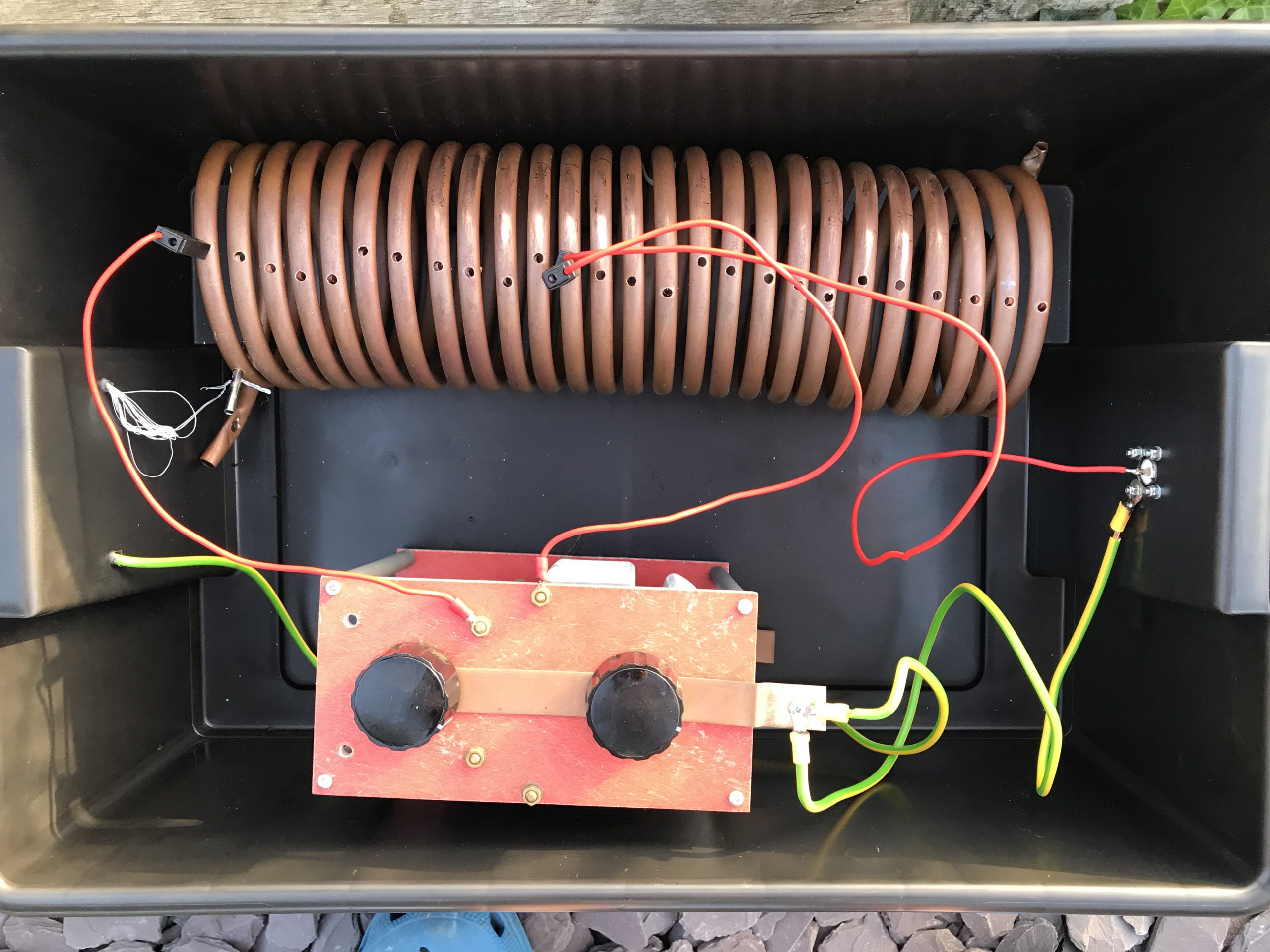
M0AWS Homebrew Pi-Network ATU
Since I still had the components of the Pi-Network ATU that I built when I lived in France I decided to reuse them as it saved a lot of work. The inductor was made from some copper tubing I had left over after doing all the plumbing in the house in France and so it got repurposed and formed into a very large inductor. The 2 x capacitors I also built many years ago and fortunately I’d kept locked away as they are very expensive to purchase today and a lot of work to make.
Getting the Inverted-L antenna up was easy enough and I soon had it connected to the Pi-Network ATU. I ran a few radials out around the garden to give it something to tune against and wound a 1:1 choke balun at the end of the coax run to stop any common mode currents that may have appeared on the coax braid.
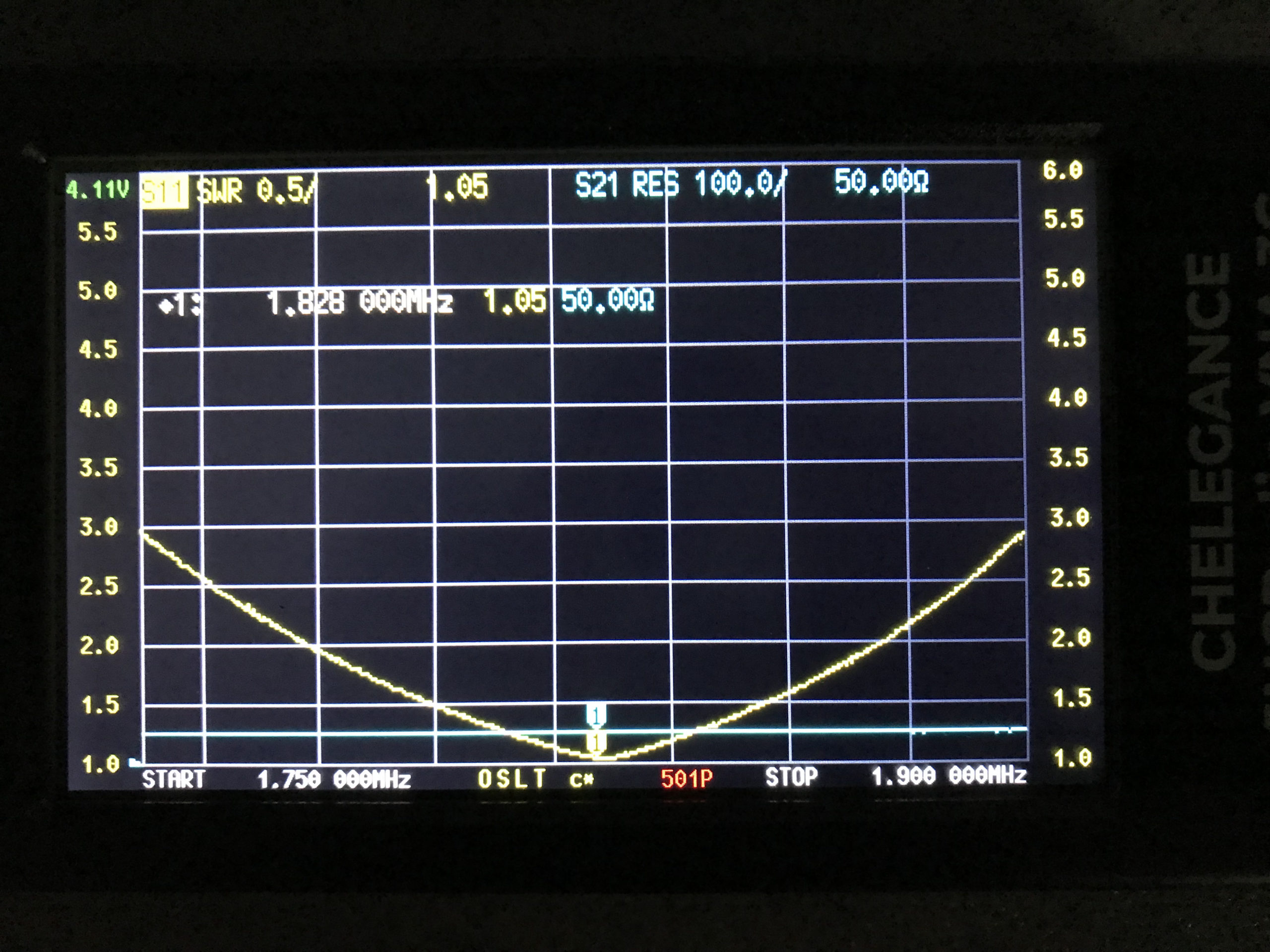
Connecting my JNCRadio VNA I found that the Inverted-L was naturally resonant at 2.53Mhz, not too far off the 1.84Mhz that I needed. Adding a little extra inductance and capacitance via the ATU I soon had the antenna resonant where I wanted it at the bottom of the 160m band.
M0AWS 160m Inverted L Antenna SWR Curve
With the SWR being <1.5:1 across the CW and FT8 section of the band I was ready to get on 160m for the first time in a long.
Since it’s still summer in the UK I wasn’t expecting to find the band in very good shape but, was pleasantly surprised. Switching the radio on before full sunset I was hearing stations all around Europe with ease. In no time at all I was working stations and getting good reports using just 22w of FT8. FT8 is such a good mode for testing new antennas.
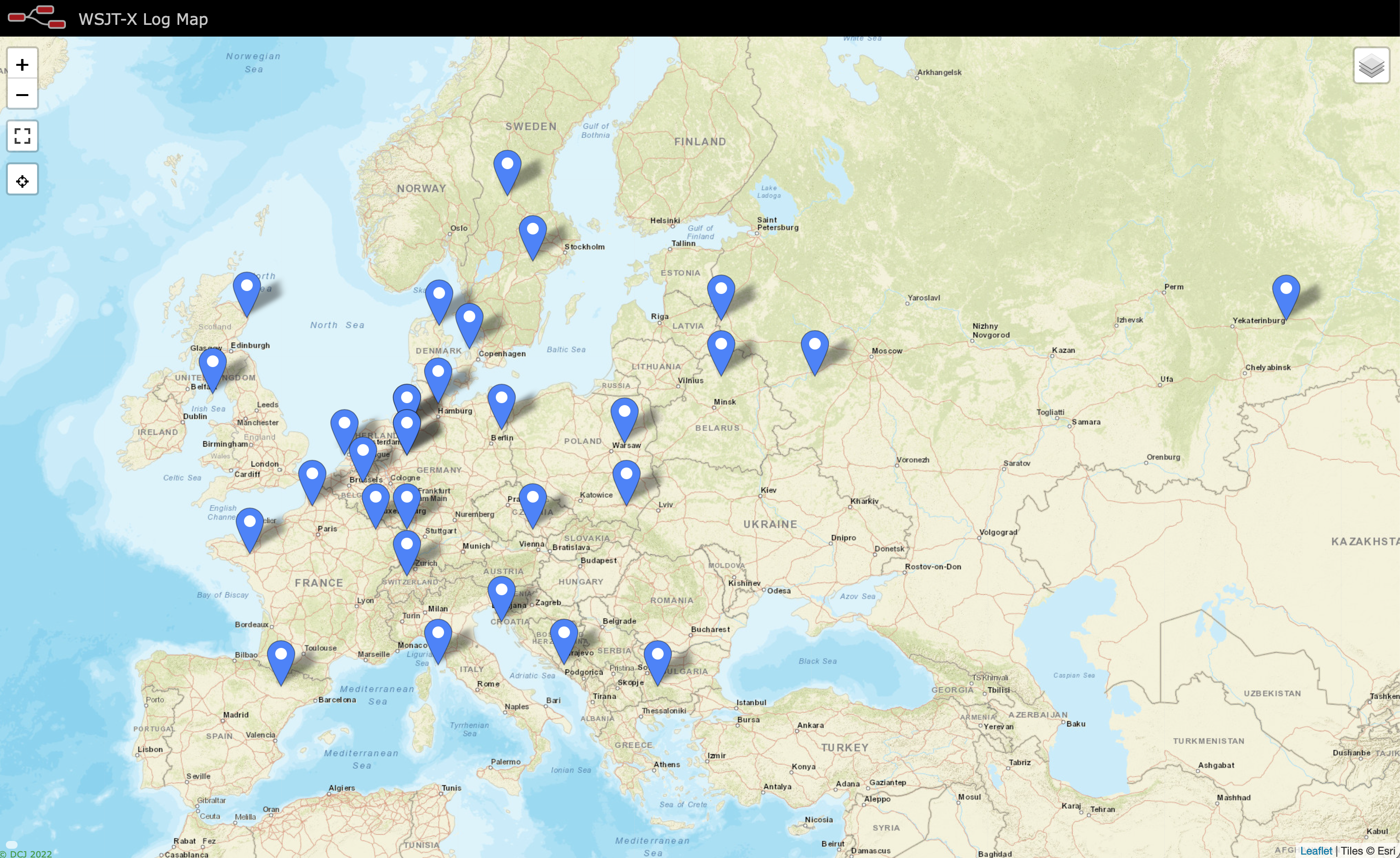
As the sky got darker the distance achieved got greater and over time I was able to work into Russia with the longest distance recorded being 2445 Miles, R9LE in Tyumen Asiatic Russia.
In no time at all I’d worked 32 stations taking my total 160m QSOs from 16 to 48. I can’t wait for the long, dark winter nights to see how well this antenna really performs.
M0AWS Map showing stations worked on 160m using Inverted L Antenna
The map above shows the locations of the stations worked on the first evening using the 160m Inverted-L antenna. As the year moves on and we slowly progress into winter it will be fun to start chasing the DX again on the 160m band..
UPDATE 6th October 2023. Been using the antenna for some time now with over 100 contacts on 160m. Best 160m DX so far is RV0AR in Sosnovoborsk Asiatic Russia, 3453 Miles using just 22w. Pretty impressive for such a low antenna on Top Band.
Since purchasing my Icom IC-705 radio I’ve only used it on the HF bands. Since the IC-705 is a “shack-in-a-box” I thought it was about time I ventured up onto the VHF/UHF bands and add another string to my bow.
Since I don’t have an antenna for these two bands I’d need to build something. I’m not really interested in DXing on the VHF/UHF bands as I’d need a yagi or two, a rotator and would need to get the entire setup up high on the chimney on the house.
We’re very fortunate in that there are a good many repeaters on VHF/UHF in East Anglia with quite a few being well within range of my QTH.
So I decided to go with a simple vertical antenna of some sort that I could easily attach to the top of a 10m spider pole and pop up in the garden without too much hassle.
The simplest of all antennas to build for any band is an end fed vertical dipole. It’s made purely from a piece of coax cable, you can’t get much simpler.
Using some dimensions I found online I unrolled a length of RG58U and set about cutting it to resonance for the two bands.
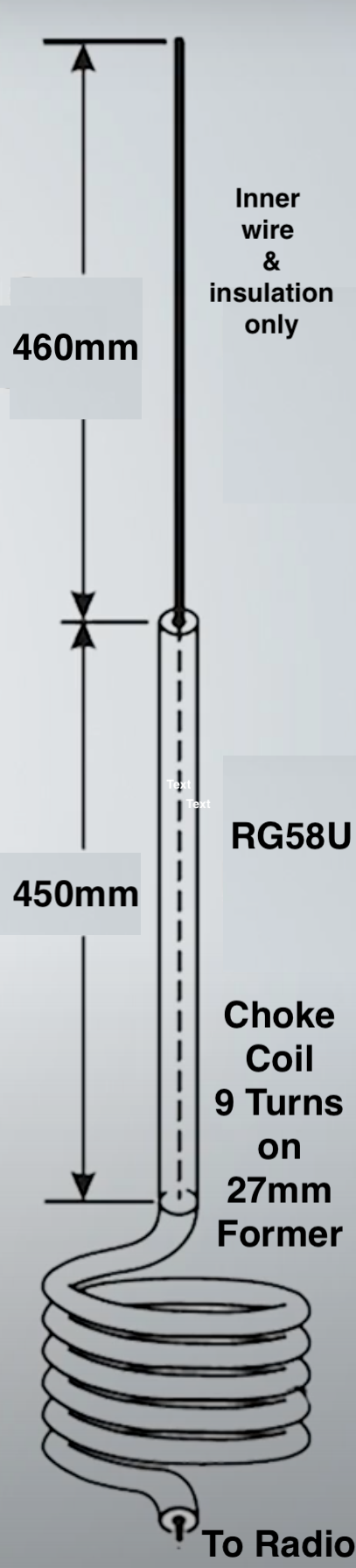
To start I measured out 910mm of RG58U and put a piece of tape around the cable at the 910mm point. I then stripped the top 460mm of the outer and braid from the coax so that the inner wire and plastic insulation was exposed. This then left 450mm of coax with the braid still in place to make up the 2nd half of the vertical dipole.
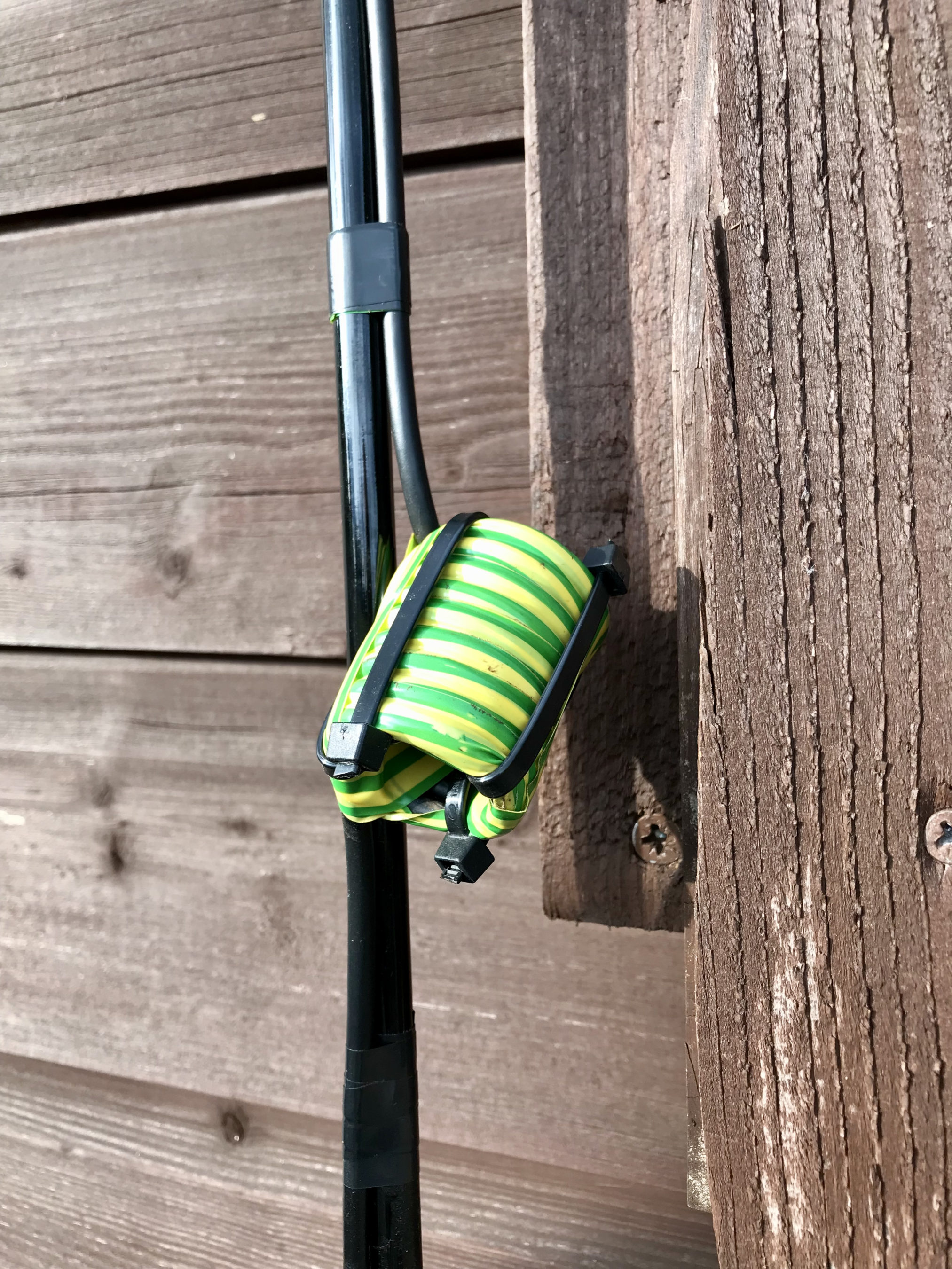
At the 910mm marker I wound the coax 9 times around a 27mm former to create a choke balun. I taped the coil up to ensure it kept it’s shape, removed it from the former and then used a few zip ties to hold it in place.
VHF/UHF End Fed Vertical Dipole Diagram
The diagram above aids in visualisation of the make up of the antenna that is made from a single piece of RG58U coax cable.
Choke Balun made from 9 turns of RG58U on a 27mm former
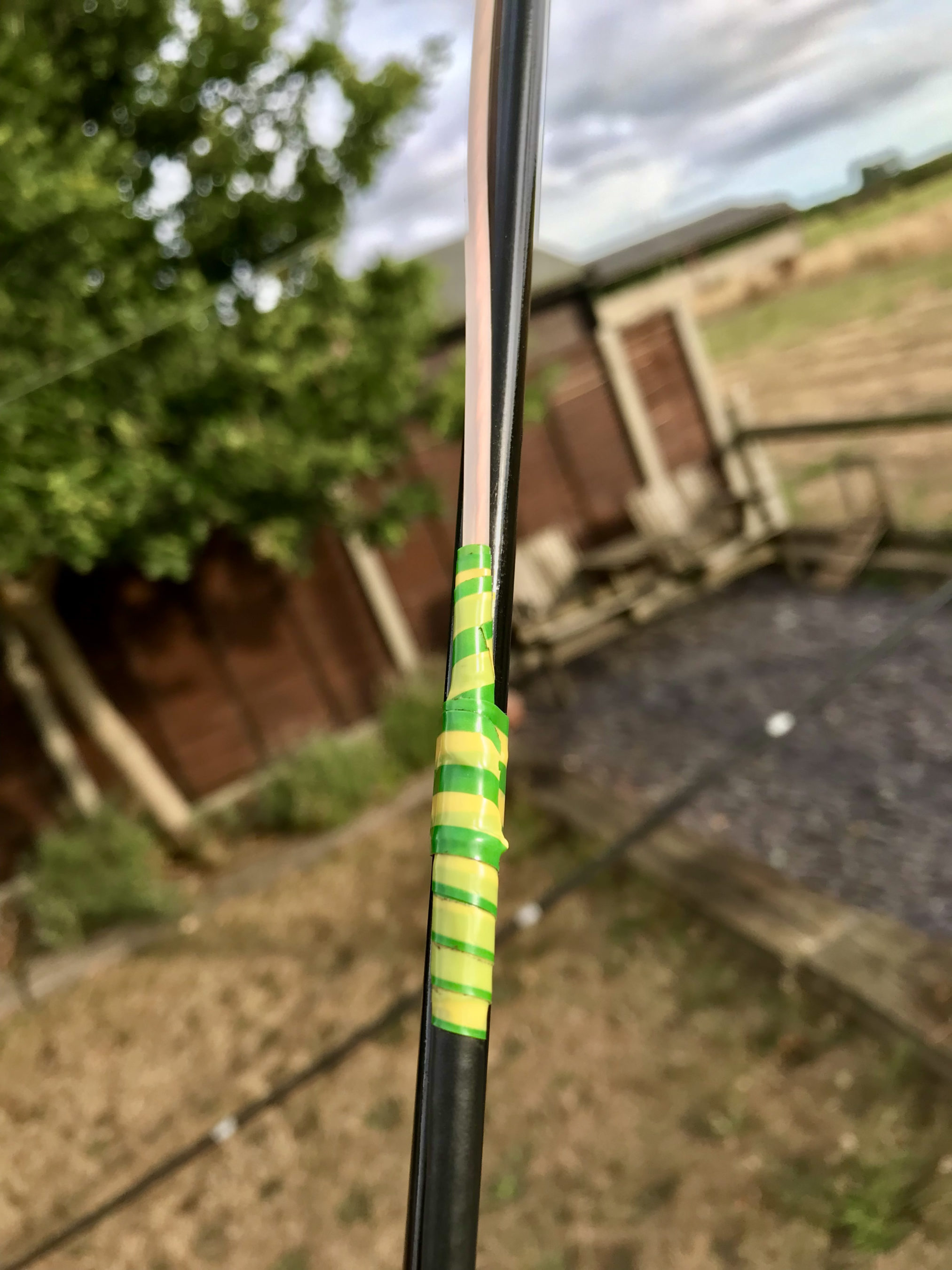
I next wound some electrical tape around the point on the antenna where the outer insulation and braid ended so that it would stop moisture getting into the rest of the coax and causing problems in the future. I also put a bit of electrical tape across the top of the end of the wire to stop moisture getting into the inner wire and then a piece of electrical tape around the wire to ensure it was fully sealed.
Electrical tape wound around the point where the outer braid finishes
At this point the antenna was complete! It literally took a few minutes to make. I could now either cut the coax a few centimetres from the bottom of the coil and fit a PL259 or just continue the coaxial cable back into the shack and fit a PL259 on the end. I decided to go with the latter as it’s one less connection to make.
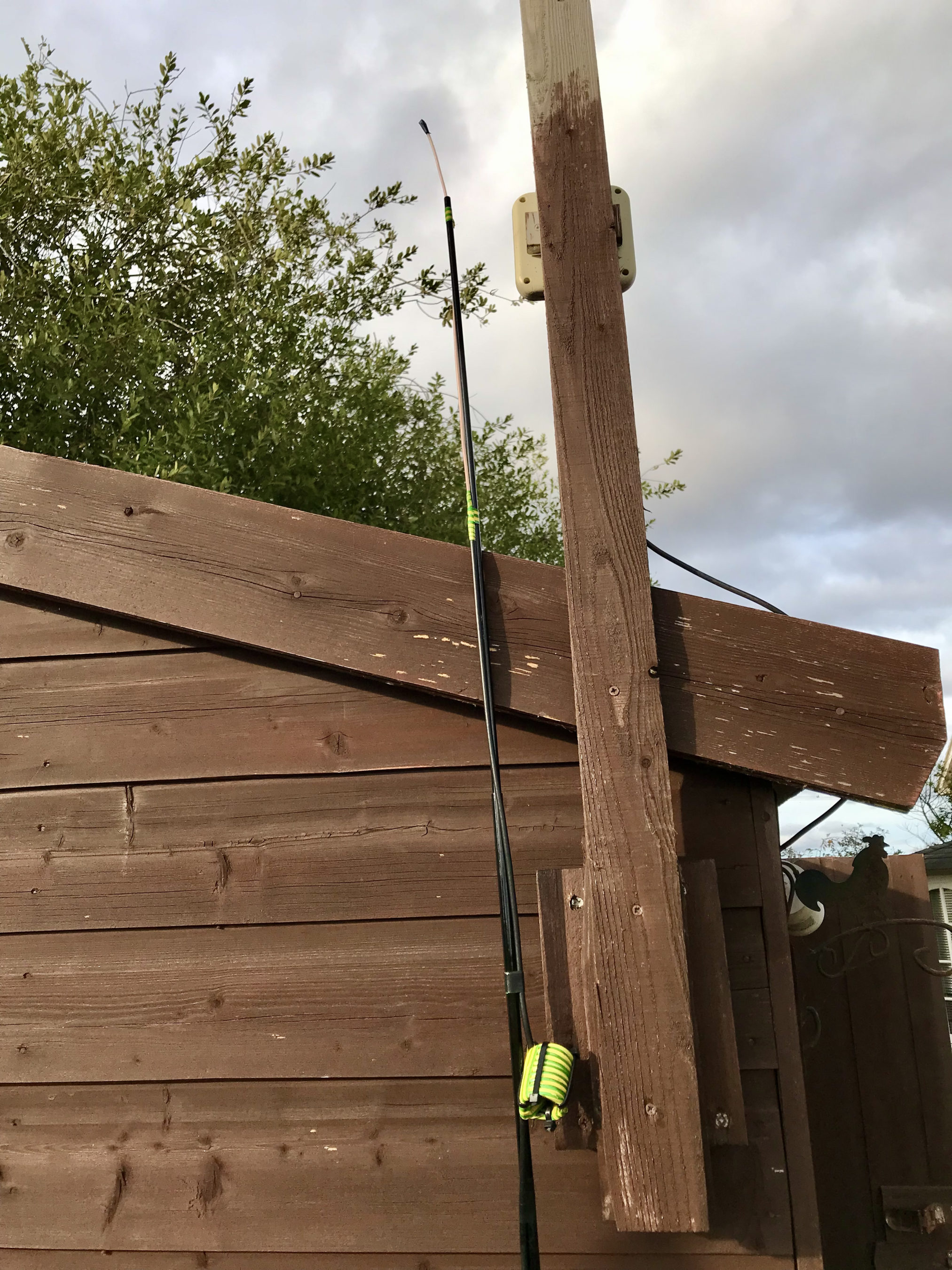
VHF/UHF End Fed Vertical Dipole taped to the top of a 10m spiderpole
Once complete, I taped the antenna to the top of a 10m spider pole and then ran the rest of the coax back into the shack and soldered on a PL259 connector.
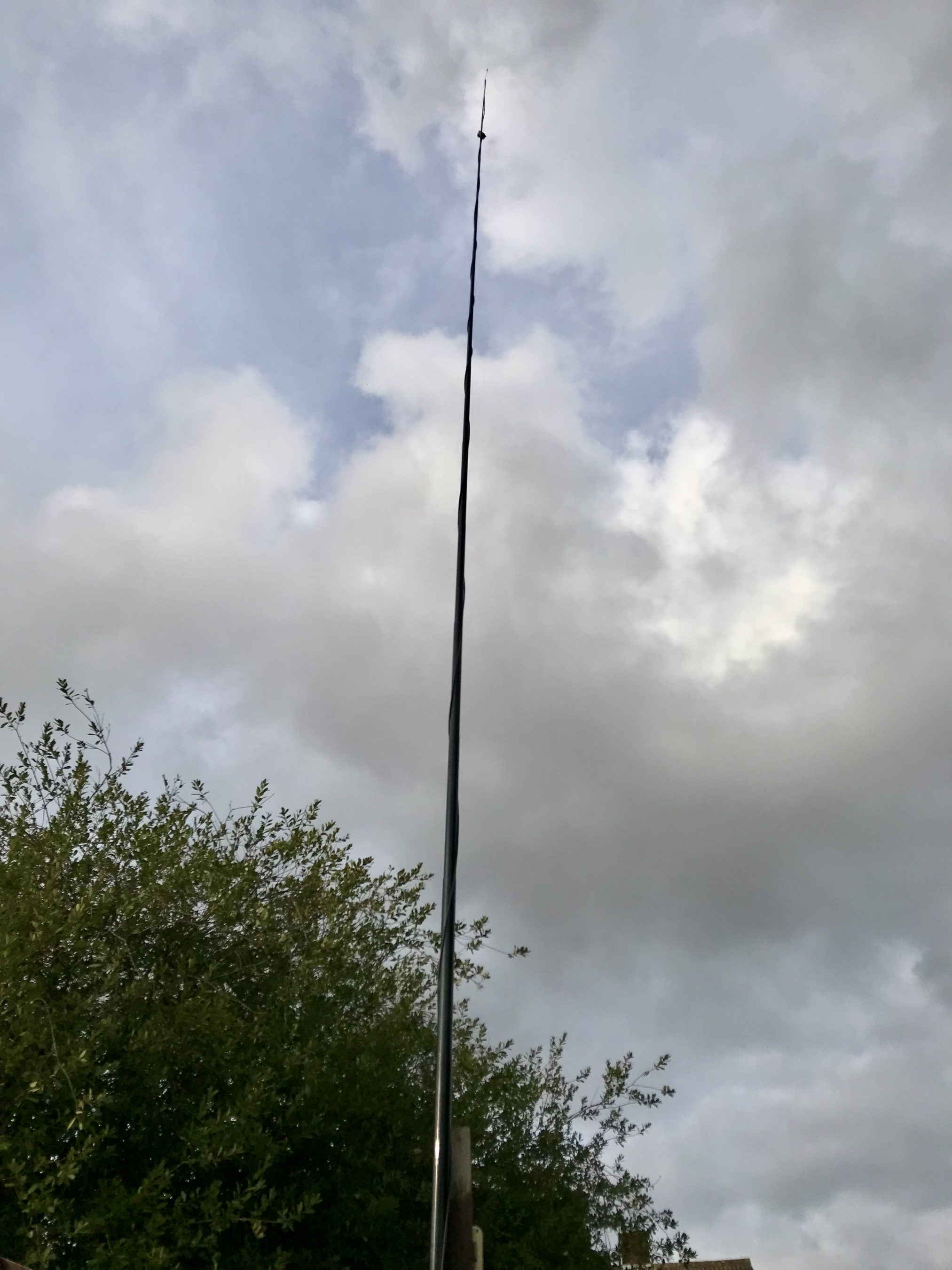
Raising the spider pole up to its maximum length put the antenna some 10m up above the ground. Hopefully this will give me a relatively clear path to the local repeaters.
Plugging the antenna into the IC-705 and checking the SWR I found it was <1.2:1 across the entire 2m band and <1.5:1 across most of the 70cm band. It was perfect for what I wanted!
VHF/UHF End Fed Vertical Dipole up 10m on a Spiderpole
I configured the local repeaters into the the IC-705 memories so that I could easily switch from one repeater to the next with all the appropriate tone and duplex frequency shifts set at the touch of a button.
My local 2m repeater GB3PO comes in at 5/9+10dB without any preamp and the local 70cm repeater GB3IH comes in at 5/9+5dB without any preamp. I was really pleased with the results and set about having a chat with other local HAMs on the local repeaters. It’s been a while since I’ve used the mic on this radio and it made a nice change!
To my surprise I found I could get into far more repeaters than I ever imagined. GB3NB in Norwich is 5/8 as are a number of repeaters down in Essex. This gives me quite a scope for chatting on the VHF/UHF bands via the repeater network.
To my surprise I can also hear ON0WV in Brugge Belgium, unfortunately it’s on the same frequency as the local 2m GB3PO repeater and so often gets drowned out completely but, it’s good to know that when there’s a lift in propagation I should be able to get into the near continent without too much hassle.
If you’re looking to build a simple but, effective 2m/70cm vertical for local repeater access then I highly recommend making an end fed vertical dipole. It only takes a few minutes to cut the cable to length, remove the outer sheath and braid and wind the choke balun, it really couldn’t be any easier.
Since getting my Icom IC-705 I’ve had problems with computer noise causing interference when connected via USB. I solved the problem mostly by winding both the USB and coax cables around 240-31 ferrite toroids. This resolved the problem nicely on all HF bands except 10m. With further investigation I realised that the 240-31 ferrite toroid doesn’t provide much choking resistance at 28mhz and so a 240-43 would be better for the higher bands. This would mean I’d need a longer USB cable and coax to the AH-705 so that there was enough cable to wind around two ferrite toroids to cover all the HF bands.
Whilst this will almost certainly provide a complete solution to the problem there is of course another way around this issue. The IC-705 is a rare beast in that it has wifi capability built in. The wifi on the IC-705 is capable of operating in one of two different modes, Access Point (AP) and Station, a host on an existing wifi network.
Since I connected my IC-705 to my in-shack wifi I am using the radio in station mode for connectivity via wifi. By connecting it this way my MacBook Pro will also have access to the internet at the same time as connecting to the radio giving me the best of both worlds.
You can of course put the radio into AP mode and connect your computer directly to it via wifi however, you won’t have any internet access from the computer as it will be connected directly to the radio. This is how it will be used when in the field for portable operations unless you have a portable 3/4/5g wifi router.
Getting the radio connected to my shack wifi was easy, just go into the IC-705 menus, switch the WLAN on, pick the SSID of my wifi router and enter the password, the radio connects immediately. You will also need to switch on the network control option and also set up a user and password that is used when connecting to the radio from your computer. Refer to the IC-705 manual on how to do this if you haven’t done it already.
To be able to use the radio wirelessly from any Apple Mac computer you will need 2 applications, WFview and Blackhole. Both of these applications are Opensource Software, I’m a huge fan of Opensource Software and have over the years been involved in a number of opensource projects.
I’m fully aware that there is an application called SDR Control available on the Apple App Store for around £90.00 that can be used instead to connect to the IC-705 wirelessly however, I prefer to use Opensource software where possible.
Before proceeding with the instructions below make sure you have an up to date backup of your system. This installation and configuration shouldn’t cause any issues at all, it worked fine on my MacBook Pro but, it’s always best to backup before you install more complex software like this.
First you need to download WFView from the Download page, make sure to download the MacOS Universal package which was v1.1 at the time writing this article. Do **not** install WFView yet, the sequence of installation is important!
WFView Download page showing the MacOS (Universal) Package v1.1
Next download the Blackhole Virtual Audio Cable application from the download page. You will need to enter an email address and your name to be able to download the application. It’s not clear how much email/spam will be sent to you but, you will need to get at least one email to obtain the download link with the authorisation code in it.
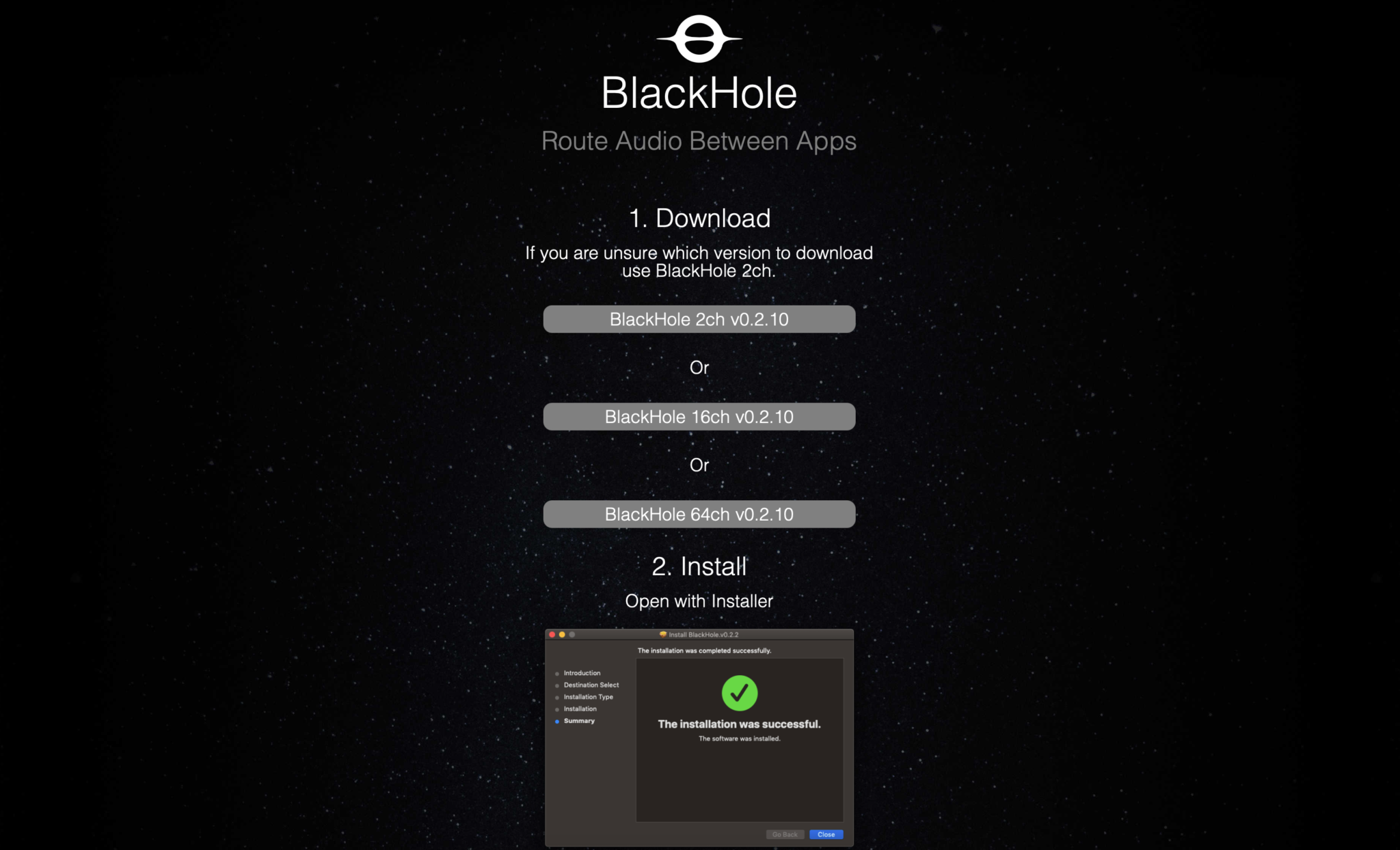
Once you’ve entered the information and submitted it you will get an email with a URL enclosed, click the URL and goto the download page. On the page there are 3 options available for download, select the “Blackhole 2 Ch” option only. At the time of writing this v0.2.10 was the current version available.
Blackhole Download page showing the 3 options available
Once downloaded you need to install the Blackhole application first as it will create the necessary virtual audio cable for WFView to use to provide sound to WSJT-X and other digital mode applications. Installation is simple and follows the normal MacOS installation process. Double click the installation package and follow the prompts accordingly.
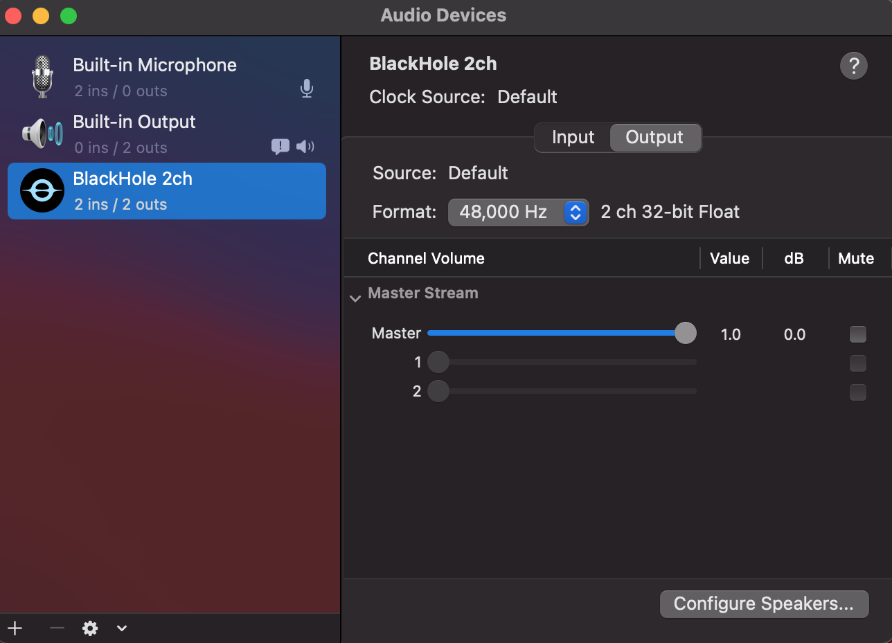
Once installed reboot your Apple computer to make sure it starts up OK with the new kernel module installed. When your system comes back up, login and open the “Audio Midi Setup” application. (The Midi app is in Applications >> Utilities)
Once the application opens you should see that you have a new audio device called “Blackhole 2ch”. On both the Input and Output tabs set the format to 48,000Hz. This setting will get the best results when using applications like WSJT-X for FT4/8 digital modes.
Apple Audio Midi Setup showing 48,000Hz selected
Leave everything else as default setting in the Audio Midi App, nothing else needs changing. Leave the Master volume at the default max as levels are controlled from the other apps.
Once you’ve set the 48,000Hz on the two tabs quit the audio midi app as it’s no longer required.
Next you need to copy the WFView app that you downloaded into the Applications folder on your Mac. Once in the applications folder you can create a shortcut to it on the dock by dragging and dropping the app icon onto your dock bar.
Next goto your IC-705 and go into the WLAN settings and make a note of the IP Address assigned to the radio from your wifi router. You will need this IP Address later.
At this point you are half way to having wireless control of your IC-705.
Start the WFView application and goto the settings tab.
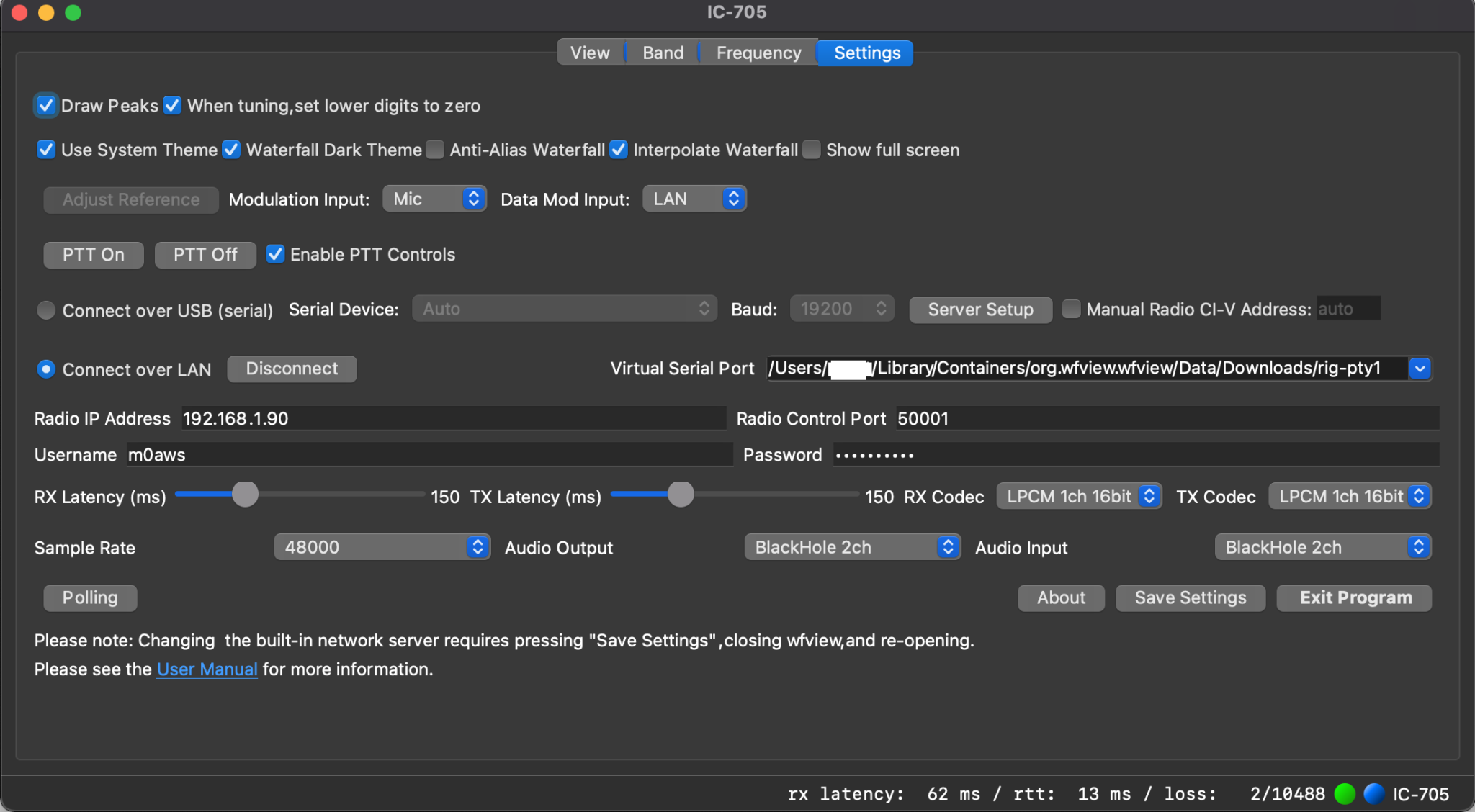
The following settings need to be made:
1: Set Data Mod Input to LAN
2: Click the Connect Over LAN radio button.
3:Enter the IP Address from your IC-705 into the Radio IP Address field.
4: Make sure Radio Control Port is set to 50001
5: Enter the Username you configured on your IC-705 into the Username field
6: Enter the Password you configured on your IC-705 into the Password Field
7: Set Sample Rate to 48000
8:Set Audio Output and Input fields to BlackHole 2ch
9: Select the first option available in the Virtual Serial Port field. This should be as shown below:
Leave all other settings as default and click Save Settings and then Exit Program.
You must exit the application in order to restart it with all the new settings.
WFView Settings tab showing all the necessary settings whilst connected to the radio
Start the WFView application again and goto the Settings tab. Click on the Connect Button.
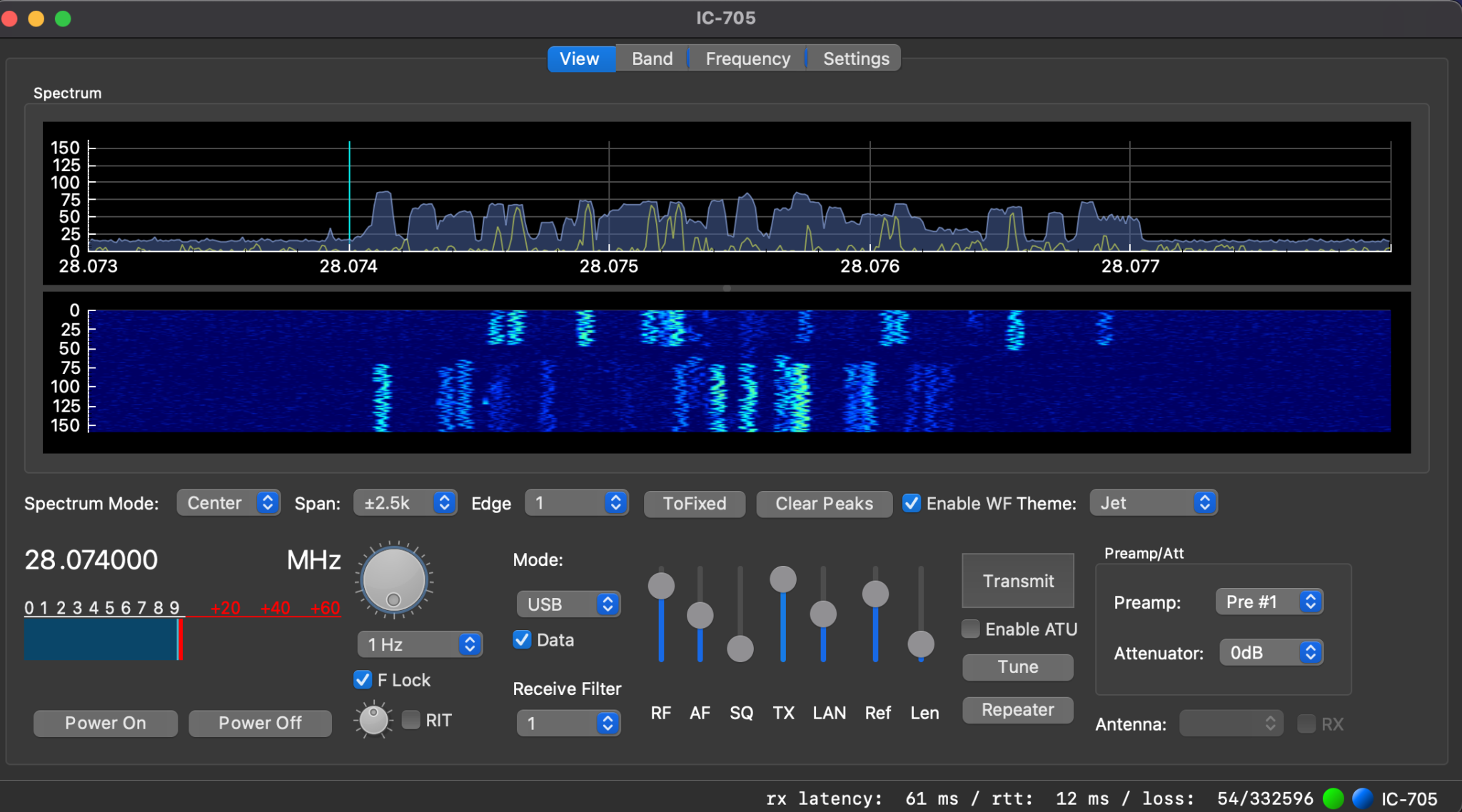
Once it has connected to the radio you will see the RX Latency details etc on the bottom right of the window. Click on the View tab and you should now have an active waterfall.
At this point you have full control of your IC-705 wirelessly. Have a play with the application and get familiar with it.
Fully operational WFView connected to my IC-705 receiving FT8 on 10m
Once I had WFView operational I set about getting WSJT-X connected to the radio wirelessly. This is actually really simple to do and just needs a couple of changes to the settings to make it work.
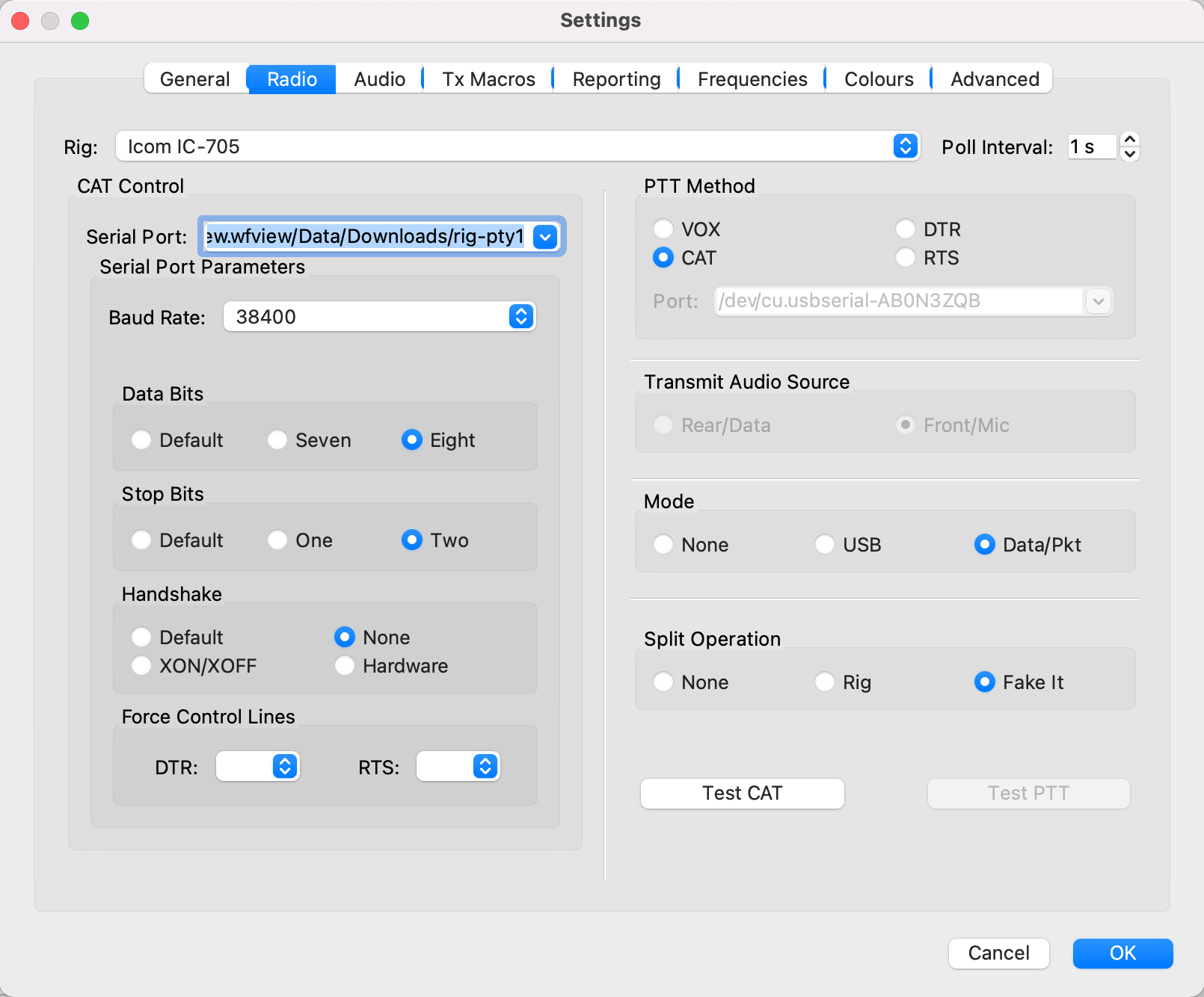
Start up the WSJT-X application and goto the Radio Settings tab. On this page you need to set the radio to IC-705, serial port to that shown below (Also shown in point 9 in the WFView section above) and Baud Rate to 38400.
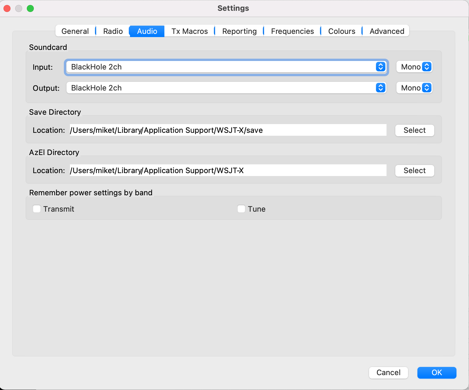
Next select the WSJT-X Audio Settings tab and set the soundcard Input/Output fields to Blackhole 2ch. Set both Input and Output to Mono as shown below.
WSJT-X Audio settings
Click OK and return to the WSJT-X main screen. You should now be fully operational for WSJT-X digital modes.
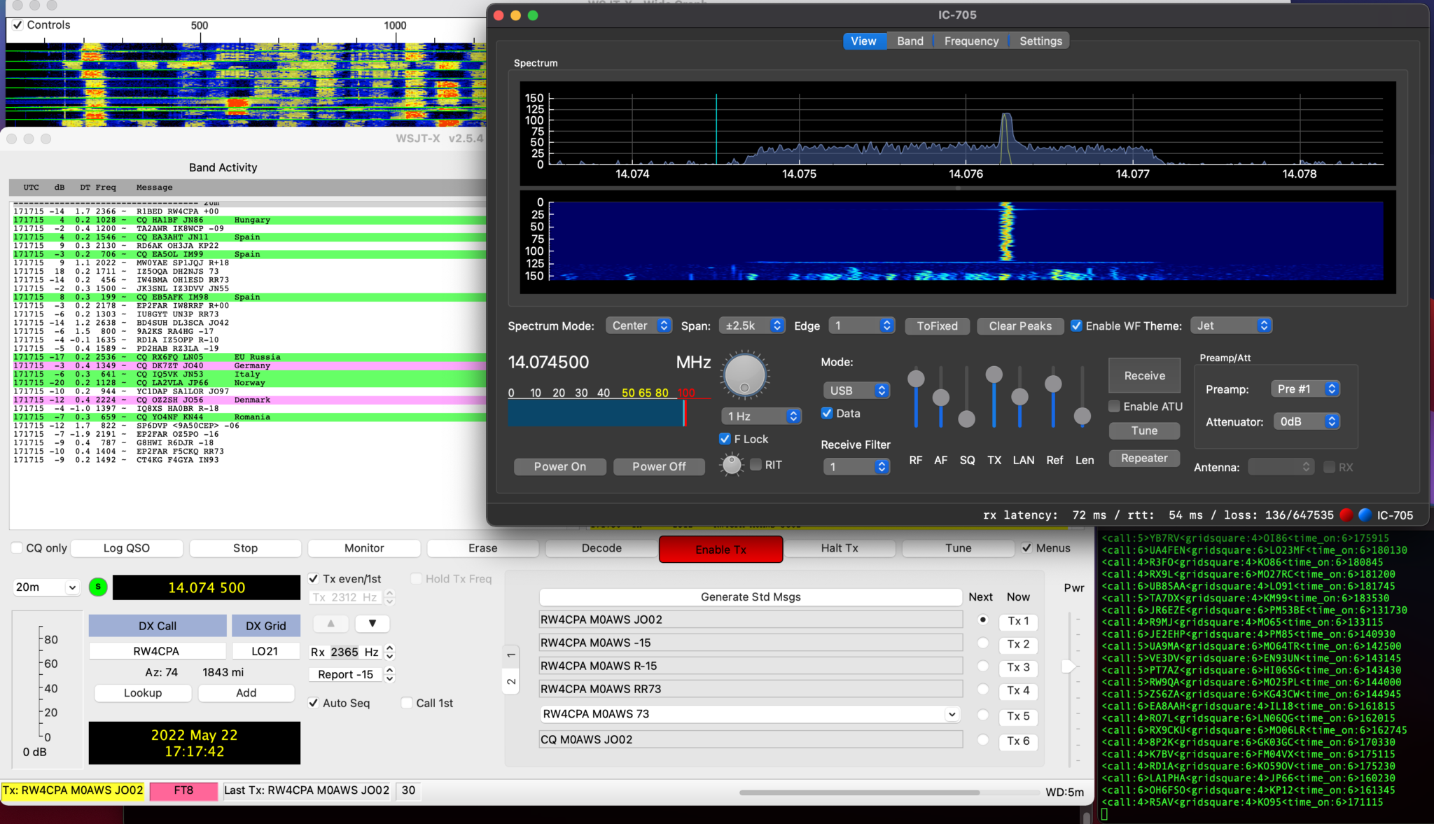
WSJT-X transmitting through WFView to the IC-705
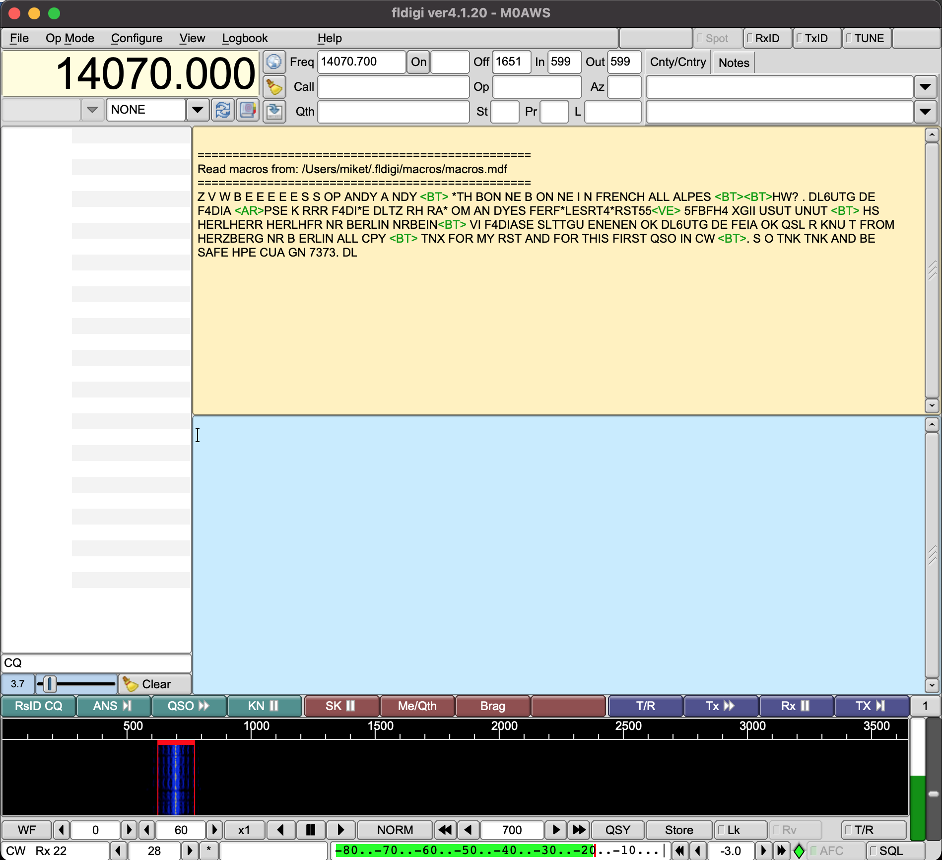
Once I’d made a few contacts with WSJT-X in FT8 mode I went on to try and get FLDigi working with WFView as well.
Unfortunately at the moment I cannot get CAT control working in either FLDigi or FLRig, neither will accept the /dev/ttys000 as the serial device however, I was able to get the audio working into FLDigi and even decoded some morse with it. I need to do little more work to fathom out why the CAT control doesn’t work in these two applications. I’m sure there is a way to resolve this but, I just need to put in a little more time to find the solution.
FLDigi decoding Morse code via WFView
UPDATE: There was some concern in one of the IC-705 Facebook groups that Blackhole wouldn’t work after a MacOS update. I’ve just upgraded my Macbook Pro to MacOS 11.6.6 and BlackHole is still fully functional afterwards. The MacOS update has no effect on the BlackHole service whatsoever. So you can rest easy!
Since getting my Icom IC-705 I’ve had a constant issue with interference on the HF bands from the USB connection on the radio when the AH-705 remote auto ATU is connected.
If I use the radio without the AH-705 inline there is no issue at all but, as soon as the AH-705 is connected to the radio there is some 9 S points of computer data noise across all the HF bands rendering them unusable.
Reading online this appears to be a common issue and so I set about trying to find a resolution.
The noise is most likely being induced onto the outer braid of the screen on the cables and so I decided to look into making a common mode choke.
Visiting the HAM Goodies website I ordered a couple of FT240-31 Ferrite Toroids as I’d read this particular mix is ideal for making common mode chokes.
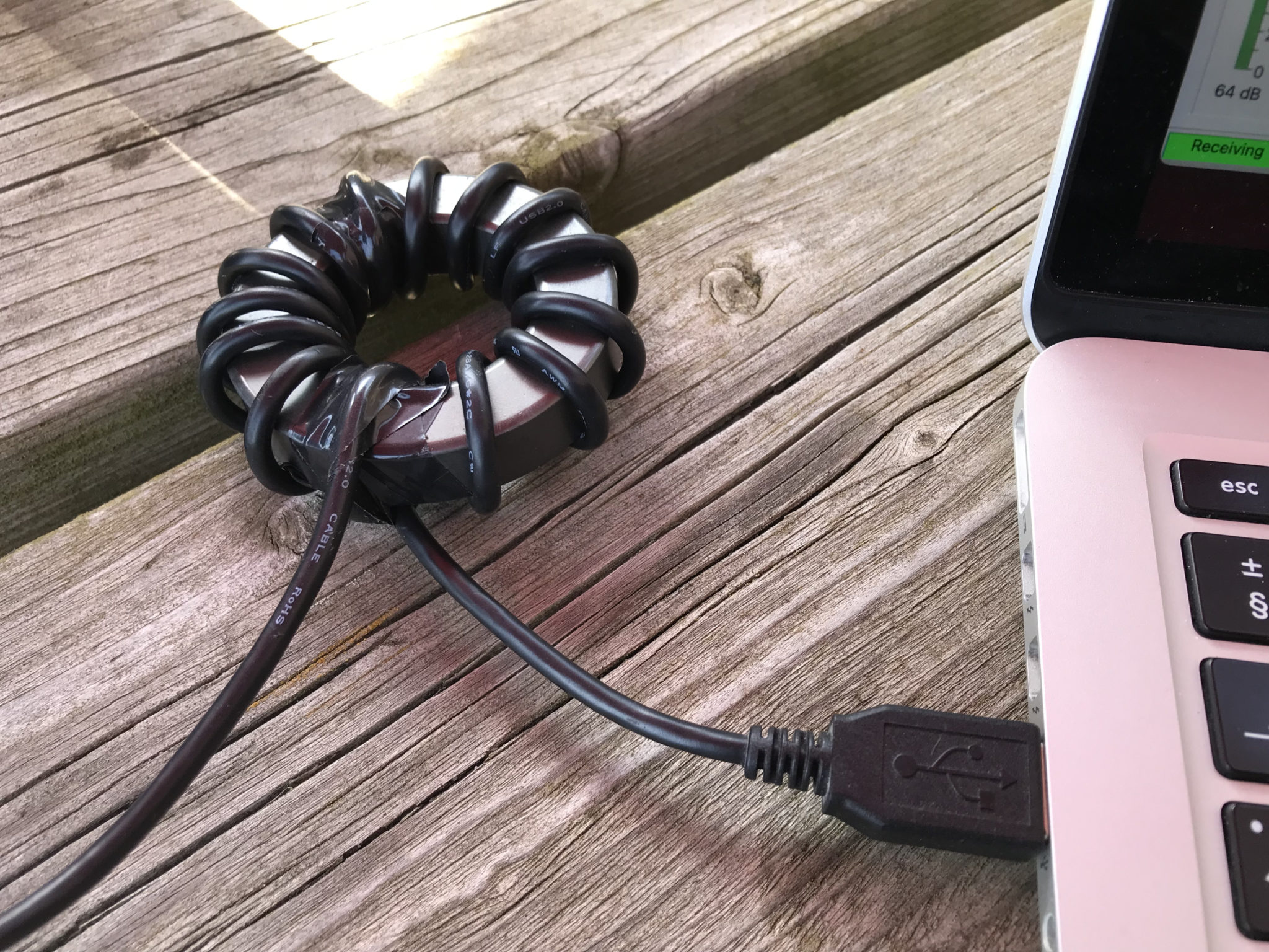
USB Cable wrapped around a FT240-31 Ferrite Toroid to create a choke
I wrapped a long USB cable around the toroid and used some tape to hold the cable in place, it’s surprising how much length is lost by simply wrapping around what looks like a very small toroid.
Firing up the radio the noise was reduced considerably but, it was still there and so I decided to do the same to the coaxial cable between the AH-705 and the IC-705.
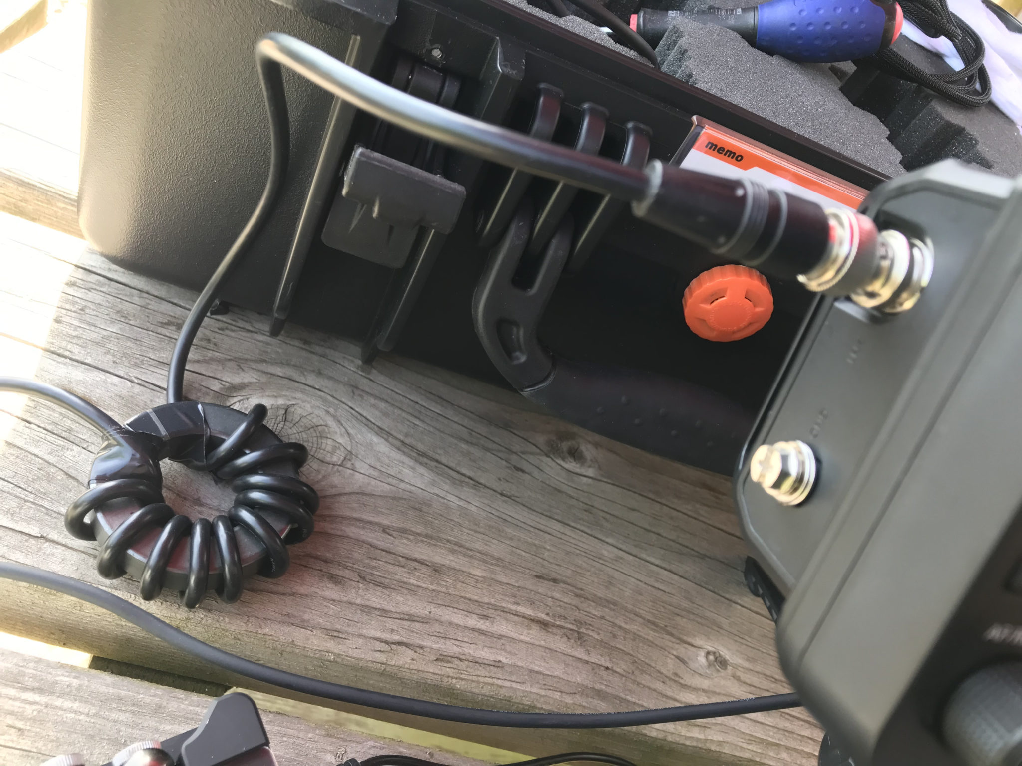
Coaxial cable between AH-705 and IC-705 wrapped around a FT240-31 Ferrite Toroid
Once I’d wrapped the coax around the toroid and reconnected the coax between the radio and ATU I was pleased to see that the computer data noise was now gone on all bands except for the 10m band. For some reason the 10m band interference is still as strong as it was without the toroids in place.
I’m not too sure why this is. I tried more and less turns on the toroid to no avail and so eventually I decided to just live with it for the time being.
At least now I can use 160m -> 12m without any interference whatsoever, a massive improvement on what I had before.
I need to do some more research on the different mixes of the ferrite toroids and perhaps trying a different mix will resolve the problem on the 10m band too.
More soon …
We use cookies to ensure that we give you the best experience on our website. If you continue to use this site we will assume that you are happy with it.