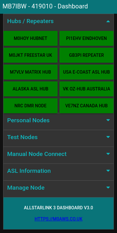
I’ve recently built a new AllStarLink (ASL) node for my MB7IBW gateway that I have recently brought up on air on the 2m band.
AllStarLink 3 has a lot of changes in it when compared to the previous version and this of course impacts my Node-Red Control Dashboard that I’ve been using to manage my first ASL node for well over a year now.
To build the node I used the RaspberryPi imager and added the AllStarlink 3 image as detailed on the allstarlink.org website.
Installing the system this way makes it pretty easy compared to previous installs but, it comes with some quirks which cause issues with Node-Red.
From the outset the plan has always been to have AllStartLink 3 and Node-Red running on the same Pi4 to keep it totally self contained. This was easy enough to achieve and works without issue.
Node-Red Control Dashboard for AllStarLink 3
Installing Node-Red onto a Pi4 is really easy and is fully documented on the Node-Red Website.
Once the AllStarLink 3 operating system was installed on my SD card, booted and operational I installed Node-Red. I soon realised that there were a few things I had to do before loading the Node-Red flow.
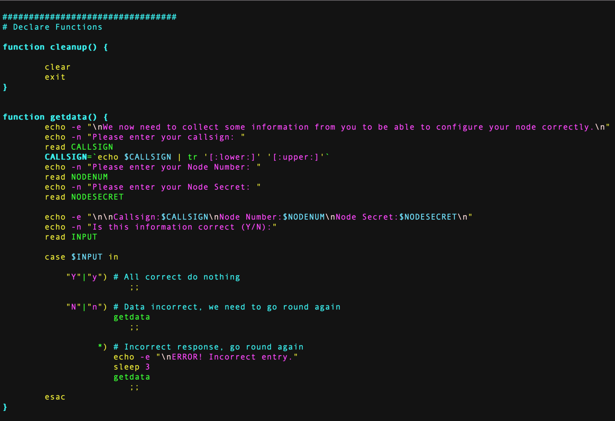
AllStarLink 3 no longer logs connect and disconnect messages in the connectlog like it did in AllStarLink 2. To get logging working again I had to create two new BASH scripts as detailed below and put them into /etc/asterisk/myscripts.
For the connect information I created the BASH script as detailed below.
Next I disabled the temporary filesystems that are used by default for the apache and asterisk logging as it’s useful to keep the apache logs for debugging and I needed the asterisk logs for the Node-Red dashboard.
Disabling the temporary file system is very easy to do, just edit the /etc/fstab and comment out the two lines as shown below.
# Comment out the next line for persistent Apache logs
#tmpfs  /var/log/apache2        tmpfs   defaults,noatime,nosuid,nodev,noexec,mode=0775,size=32M 0 0

# Comment out the next line for persistent Asterisk logs
#tmpfs  /var/log/asterisk       tmpfs   defaults,noatime,nosuid,nodev,noexec,mode=0775,size=32M,uid=102,gid=106 0 0

# Note: These lines are wrapped, should be on 1 line in the /etc/fstab
Once the entries in the /etc/fstab were commented out I rebooted the Pi4 to get persistent filesystems.
The final thing that had to be done was to allow user repeater to use sudo without a password so that it could be used to perform reboot/shutdown/process restart as user root from within the dashboard.
# /etc/sudoers

# Allow repeater sudo without password
repeater ALL=(ALL) NOPASSWD: ALL
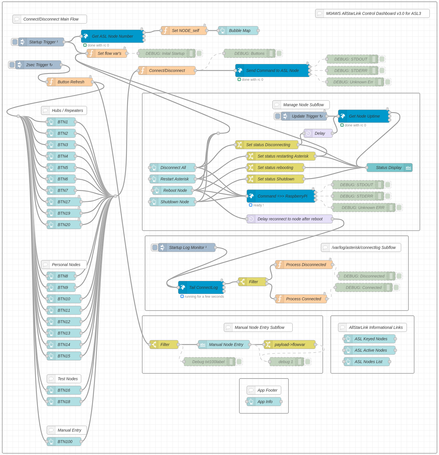
Once this was all done I imported the Node-Red flow, configured the SSH nodes with login credentials for the Pi4 (important to use the user repeater for SSH), clicked deploy and the dashboard was ready for use.
Node Red AllStarLink3 Control Dashboard Flow
I’ve been using the dashboard for a few weeks now and it’s running perfectly, without error.
If you want to build your own Node-Red Control Dashboard for your AllStarLink 3 node then, just download the flow using the button below and import it into your flow editor.
Living in a rural area we have a very unreliable mains power supply and so I have to protect all the IT equipment in my home lab with an uninterruptible power supply (UPS).
Over the years I’ve found APC UPSs to be super reliable and use them extensively around the house to keep important services running during power outages.
Running a combination of Debian and Ubuntu operating systems on my servers and virtual machines (VMs) I’ve always used the apcupsd daemon to interface with the UPS for automated shutdowns etc.
The apcupsd daemon does have a very simple web interface that can display 3 items of information at a time but, I decided it would be nice to have a view showing all the information on one dashboard.
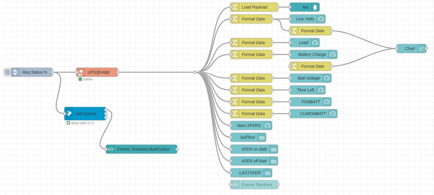
Node-Red APC UPS Flow
The Node-Red flow is pretty simple and is based around the apcrequest node that connects directly to the apcupsd service on port 3551.
Note: You must configure the apcupsd service as a NIS server in the /etc/apcupsd/apcupsd.conf config file.
Most of the info is collected via the apcrequest node however, I found that getting the events information via the node to be unreliable and so I used a BigSSH node to connect to the computer to get the UPS events information directly from the log file.
The simple flow collects the data, formats it into a useable format and then passes the data on to the dashboard GUI objects for display, it really is very simple.
Node-Red APC UPS Dashboard
The resultant dashboard clearly displays all the information needed including line voltage over time. I was surprised to see such a swing in the incoming voltage but, now understand why I get so many low line voltage and over voltage events on the UPS.
The events log is displayed in a scrolling text area on the dashboard with colour highlighting.
If you’d like to create a dashboard for your APC UPS then the flow can be downloaded below.
This is more of an aide memoire for myself more than anything but, may be useful to anyone who is using a SHARI powered AllStarLink node.
Out the box the SHARI build as documented here and here uses node numbers in announcements when connecting/disconnecting. The information in this article will change this so that the announcements use the node callsigns instead of node numbers.
As user repeater, login to the RaspberryPi that the SHARI is connected too via SSH and make the following changes:
1: Using your favourite command line text editor, edit /usr/sbin/write-node-callsigns and change SRCDIR to point to /var/www/html/allmon2
# 28/08/24 - M0AWS - Changed path to point to allmon2
##SRCDIR=/var/www/html/allmon
SRCDIR=/var/www/html/allmon2
2: Copy the astb.txt file into the necessary directory:
NOTE: The info in this article is out of date and does not work with the latest version of AllStarLink. The Debian O/S it is based on is no longer in support.
Over the last couple of days in-between doing other things I’ve been writing and testing a BASH shell script that will completely configure a fully working AllStarLink node.
M0AWS – Coding the BASH script for the automated AllStarLink installation
To use the script you must already have your RaspberryPi (preferably a Pi 3b) connected to your LAN with full internet access using the Raspbian based version of the AllStarLink software downloadable from here.
The specific version I use is:
asl-2.0.0-beta.6-kc1kcc-20210324-rpi-armhf
I have tested the BASH script using this specific version of O/S only.
Once your RaspberryPi 3b is up and running, has full internet access and is accessible on your local LAN, using SSH login in as the user ‘repeater‘ using the password ‘allstarlink‘.
It’s important you only use this login to configure the node as this is the user the script is expecting to be run by. You must login via SSH as the SHARI device needs to be connected to the RaspberryPi 3b and you won’t be able to connect a keyboard and mouse at the same time. (If you are using two USB cables for the SHARI device then you can use a keyboard and mouse along with a monitor attached to your RaspberryPi instead of using SSH).
Once logged in as user repeater run the following wget command to download the zipped install script:
You are now ready to build your AllStarLink node. Before you run the script make sure you have your node number and node secret to hand. These are obtained from the AllStarLink portal.
Once you’ve got all your node information you can run the script using the following command:
./install.sh
The script will now take you through the full process of updating the operating system as necessary, installing all the required packages and software. It will then reboot the RaspberryPi and you will need to login and run the script a second time using the command above.
On the second run the script will install some python specific software, ask you to enter your callsign, node number and node secret and will then configure your node. The last thing it does is configure the Allmon2 and Supermon Web Admin websites. During this process it will ask you to enter a password twice for the Admin user for the two websites, make sure you make a note of this password as you will need it to login and control your node.
Once the node is configured it will be rebooted and you will then be able to connect to your node using your favourite web browser and the user admin and the password you set above.
To access the Allmon2 web-admin system use the following URL:
For those of you who prefer Supermon you an use the following URL:
http://your-RaspberryPi-IP-Address/supermon
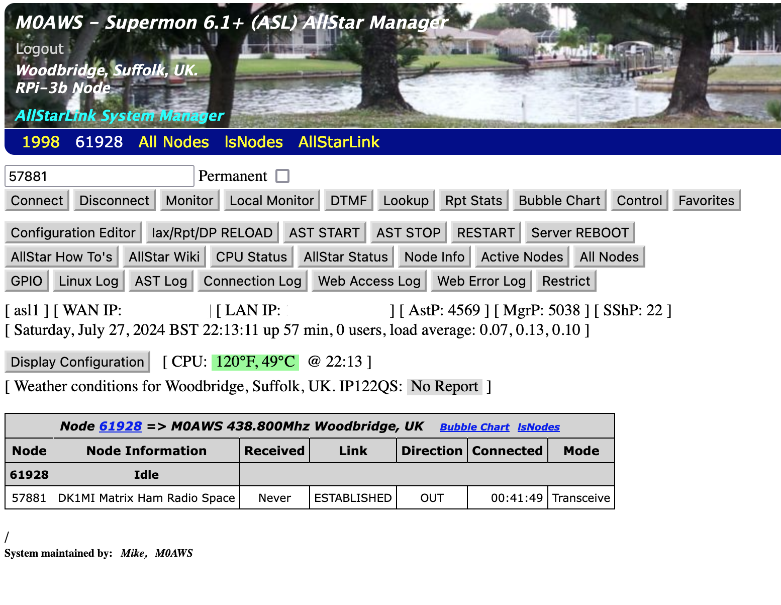
M0AWS – Supermon Web Admin view
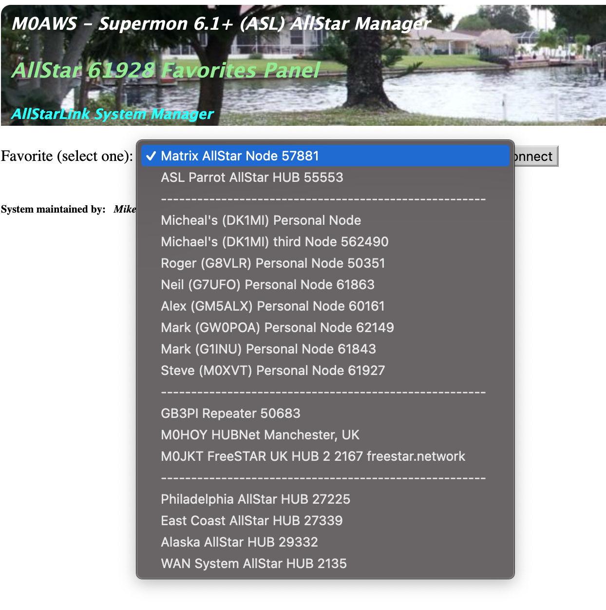
I have also pre-populated the Favorites button with a list of nodes that I use often. You can easily change these entries by editing the favorites.ini file in the /var/www/html/supermon directory as user root.
M0AWS – Supermon pre-populated Favourites drop down list
When you first login to your node via your web browser you’ll notice that it says your node isn’t in the database. You can update the database by using the following URL in your web browser:
Please note: This build is now deprecated and will no longer work. Please use the new AllStarLink 3 build process as documented on the AllStarLink website.
We’ve recently added a new room to the Matrix HAM Radio Space for Digital Voice modes as this was an area of interest that didn’t really fit into any of the other rooms.
The new Digital Voice room has attracted a lot of attention from members, with a lot of the focus being on the AllStarLink system. Michael, DK1MI built an AllStarLink node in the cloud for us all to use for Matrix Nets and so I decided I had to get in on the fun.
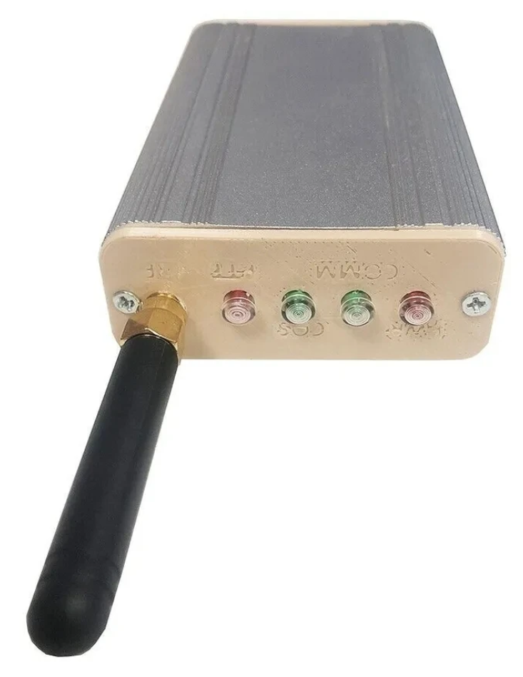
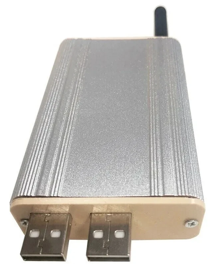
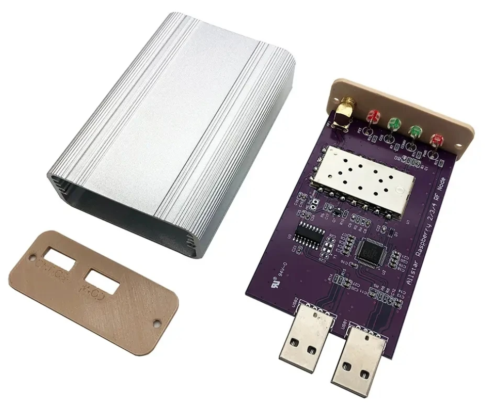
Jumbospot SHARI SA818 Amateur Radio AllStarLink Radio Interface Front Panel ViewJumbospot SHARI SA818 Amateur Radio AllStarLink Radio Interface Rear ViewJumbospot SHARI SA818 Amateur Radio AllStarLink Radio Interface stripped down View
The two USB connectors on the SHARI device are position such that they plug into two of the available 4 USB ports on the RaspberryPi without the need for cables. This keeps the whole solution together in one neat package.
Before you start you will need to obtain a node number and secret (password) from the AllStarLink Portal. To get this you will need to provide proof to the AllStarLink administrators that you are a licensed Amateur Radio (HAM) operator. This is done by uploading a copy of the first page of your HAM licence to the website for the admin team to check. This can take 24hrs to be completed so make sure you get this all done before trying to build your node. You cannot build a node successfully without a node number and secret.
Of course you will also need a transceiver that can operate on the 438.800Mhz frequency or other frequency of your choice on the 2m or 70cm HAM band.
You will also need to open port 4569 on your internet router and setup port forwarding to the IP Address that you will be using on your RaspberryPi node. It’s important to use a static IP Address on your RaspberryPi.
There are quite a few different Linux based operating system (O/S) images that are available for the RaspberryPi devices that have been specifically tailored for the AllStarLink node and include all the necessary software and library packages out the box.
Once downloaded you need to burn the ISO image onto a suitable SD card for your RaspberryPi. I use BalenaEtcher as it’s extremely quick and reliable at burning ISO images to SD cards.
Of course if you are a hardline Linux command line junkie you can always use dd to create the SD card.
Once you’ve got your O/S onto your SD card, slot it into your RaspberryPi making sure your SHARI device is connected to the two USB ports and then power it up. Make sure you have a good PSU for the RaspberryPi as the two devices together draw around 3A of current during the transmit cycle. (I use a 3.6A PSU from Amazon).
The default login for the Raspbian O/S is shown below. Login via SSH and configure your RaspberryPi for your local network. It’s important to use a static IP Address configured either directly on the RaspberryPi or via DHCP in your router.
Next you need to change directory into the asterisk config file directory using the command shown below:
cd /etc/asterisk
In this directory you will find all the default config files that come as part of the distro. For this build we’re not going to use them and so we need to move them out of the way ready for a set of config files that have already been configured correctly.
Using the following commands create a new directory, move into that new directory and then move all the unwanted configuration files into it:
mkdir ORIGINAL-CONF-FILES
cd ./ORIGINAL-CONF-FILES
mv ../*.conf ./
ls -la
cd ../
You should now be back in the /etc/asterisk directory which will now be empty apart from the custom directory which we left in place.
You now need to copy the correctly configured configuration files into the /etc/asterisk directory. Start by downloading the zip file containing the new configuration files
Download removed as deprecated.
Once downloaded, copy the .zip file into the repeater users home directory (/home/repeater) using either scp on the Linux command line or if using Windows you can use the FileZilla Client in SFTP mode using the login details above.
Once you have the .zip file in the repeater user’s home directory you need to copy the file into the /etc/asterisk directory as user root:
Next as user root, change directory into the /etc/asterisk directory and unzip the .zip file:
cd /etc/asterisk
unzip ./AllStarLink-Config-v3.zip
Once the file is unzipped you will have a directory called AllStarLink-Config in the /etc/asterisk directory. You now need to cd into the directory, copy all the files out of it into the /etc/asterisk directory leaving a copy in the AllStarLink-Config directory for future reference:
cd /etc/asterisk/AllStarLink-Config
cp ./* /etc/asterisk
cd /etc/asterisk
You now need to move a couple of files into the repeater users home directory using the following commands:
The gpioBASH script and configuration details were supplied by Mark, G1INU in the Digital Voice room on the Matrix. It adds the COS light functionality to the setup. The COS light will now light every time the SA818 hears RF on the input.
The next thing you need to do is configure the SA818 radio device in the SHARI. The script I used was originally from https://wiki.fm-funknetz.de/doku.php?id=fm-funknetz:technik:shari-sa818 all I’ve done is change the entries to switch off CTCSS and change the frequency to 438.800Mhz. Configuring the SA818 is done by running the SA818-running.pyPython programme that you moved into the repeater user home directory. Making sure you are still user root, run the following commands:
cd /home/repeater
./SA818-running.py
At this point your SHARI SA818 device will be configured to operate on 438.800Mhz and CTCSS will be disabled.
If you want to change the frequency or enable and set a CTCSS tone to access the node you will need to edit the Python programme using your favourite text editor and change the entries accordingly. Once changed rerun the program as shown above and your SHARI will be reconfigured to your new settings.
Next you need to move the allmon.ini.php file into the correct directory so that it enables access to the Allstar Monitor web page on the device so that you can manage connecting/disconnecting nodes. Use the following commands as user root to achieve this:
The allmon.ini.php file needs to have your node name entered into it to work correctly. As user root, change directory and edit the file using your favourite editor.
cd /var/www/html/allmon2
Using your text editor, search for the line starting [XXXXX] and change the XXXXX to your node number. Save the change and exit the file.
At this point you are almost complete, all that is left to do is add your node number and node secret into the appropriate configuration files in the /etc/asterisk directory.
Since I am a Linux command line junkie I use vi to edit all the configuration files on the command line as user root, but you can use any editor of your choice.
cd /etc/asterisk
Start with the extensions.conf file. Search for the line starting with NODE = and delete the XXXXX entry and insert your node number. Save the file and exit it.
Next you need to edit the iax.conf file. This time search for the line starting with register= and change the XXXXX for your node number and the YYYYYYYYYYYY for your node secret. Be careful not to accidentally delete any other characters in the lines otherwise it will corrupt the configuration file.
In the same file search for the two lines that start with secret = and change the YYYYYYYYYYYY for your node secret. Once you have changed both of the secret entries, save and exit the file.
The final file to edit is the rpt.conf file. Once again open the file using your favourite editor and search for the line starting with XXXXX = radio@127.0.0.1:4569/XXXXX, change the XXXXX entries for your node number making sure not to delete any other characters next to the XXXXX entries.
Further down in the same file there is a line that starts with [XXXXX], once again change the XXXXX for your node number making sure to keep the square brackets at each end of the node number as you edit it.
Finally move down to the very bottom of the file and find the two lines that start with /home/repeater/gpio, once again change the XXXXX entries for your node number.
The final thing to change in the rpt.conf file is to replace my callsign with your own callsign so that the node identifies itself correctly. Scroll through the file until you find the two lines shown below, delete M0AWS and add your own callsign instead making sure you keep all the spaces between words as shown below.
idrecording = |i DE M0AWS
idtalkover = |i DE M0AWS
Once this is done, save and exit the file. At this point your node should be fully configured and will only require a reboot to get it working.
As user root, reboot your raspi using the reboot command.
reboot
Once your raspi comes back online, login using SSH as user repeater and then become root user using the sudo command detailed above.
You now need to create the admin user password for the Allstar Monitor web page on the device. This is done using the following commands as user root:
cd /var/www/html/allmon2
htpasswd -c .htpasswd admin
You will be asked to enter a password twice for the admin user. Make sure you make a note of this user/password as you will need it to login to the web page.
Finally check that the controlpanel.ini.php file is in the /var/www/html/allmon2 directory:
ls -la /var/www/html/allmon2/controlpanel.ini.php
If the file isn’t shown in the directory, enter the following commands to create the file in the correct place as user root and then exit the SSH session:
cd /var/www/html/allmon2
cp ./controlpanel.ini.txt ./controlpanel.ini.php
cd
exit
Once this is done your configuration is complete, logout from the terminal session by entering exit once more and your SSH session will terminate.
Using your favourite web browser enter the IP Address of your raspi into the URL bar as shown below:
http://<Your-Raspi-IP>/allmon2
Note: remove the <> from the URL once you have entered the required information.
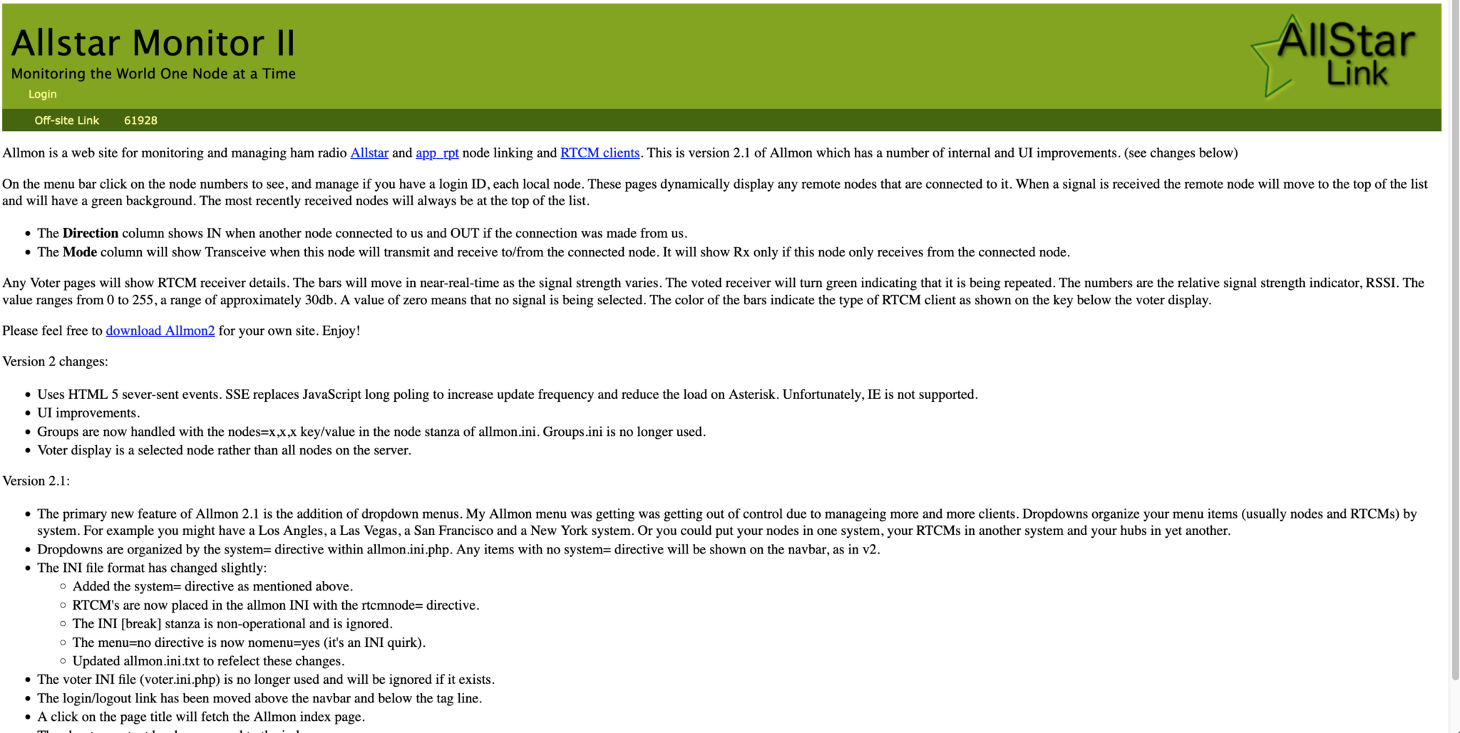
Once this is done you should be presented with your node control panel as shown below.
First visit to the AllStar Monitor Web Page
Login using Admin and the password you set above and you are now ready to start using your node.
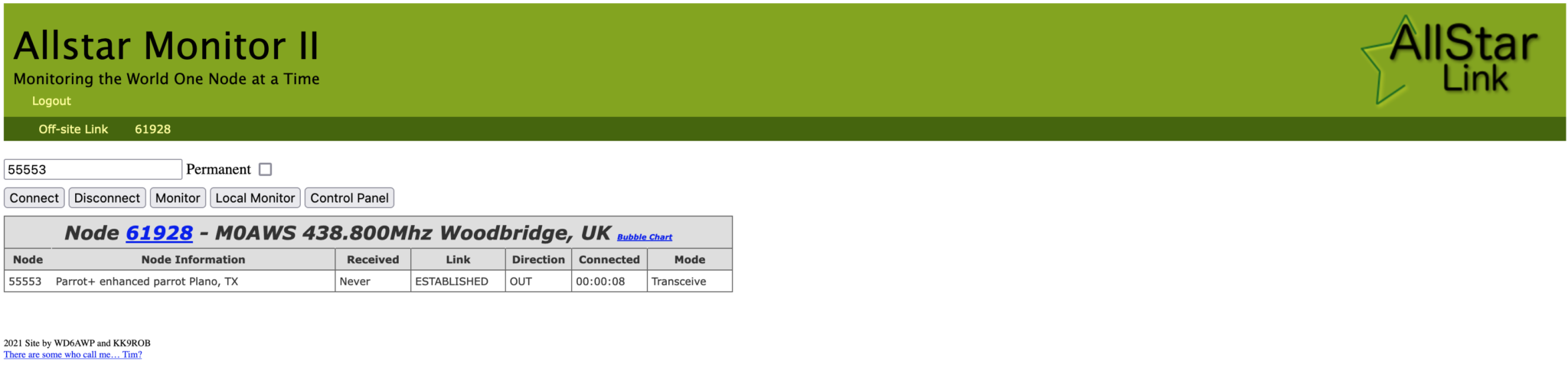
It’s a good idea to connect to node 55553 which is a parrot test node to check your audio levels. You can do this by entering the node into the field at the top left and pressing the connect button.
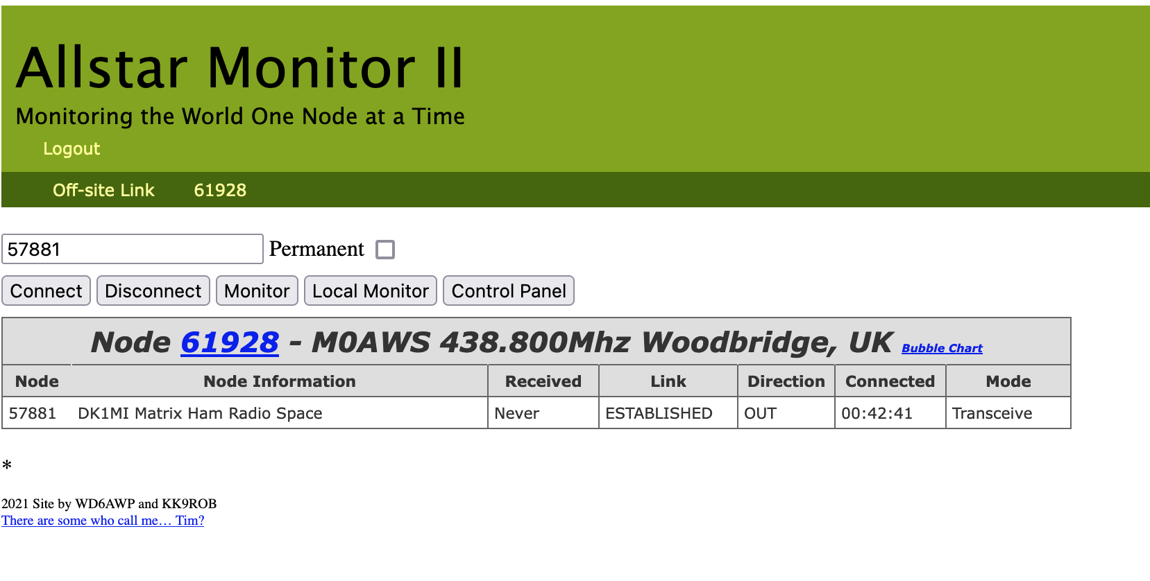
M0AWS AllStarLink Node 61928 connected to 55553 Parrot
Once connected, tune your radio to 438.800Mhz FM and transmit a test message using your callsign and test123, or something similar. The parrot will then play your recording back to you so that you can hear how you sound. It will also comment on your audio level as to whether it is OK or not.
You are now connected to AllStarLink network and have the world at your finger tips. Below is a small list of nodes in the UK, Australia and America to get you started chatting with other HAMs via your node.
57881	Matrix HAM Radio Space AllStarLink Node (Hosted by Dk1MI)
55553	ASL Parrot for testing
41522	M0HOY HUBNet Manchester, UK
60349	VK6CIA 439.275 Perth, Western Australia
51077	VK6SEG South West Hub B Albany WA
2167	M0JKT FreeSTAR UK HUB 2 freestar.network
53573	NWAG NW AllStar Group Lancashire, UK
27339	East Coast Hub Wilmington NC USA
M0AWS AllStarLink Node 61928 sitting on the equipment rack
Thanks to Michael, DK1MI for building and hosting the Matrix HAM Radio Space AllStarLink Node (57881) and getting us all started in the world of AllStarLink!
We hope to be having regular Matrix Net’s on the node soon for all Matrix members and visitors. We’ll organise days/times via the Digital Voice room.
The Weak Signal Propagation Reporting Network (WSPR) known as “Whisper” in the HAM community is a QRP/QRPp beacon mode that is used by many HAMs around the world to see pretty much realtime propagation on the HF bands.
I first started using WSPR when I lived in France some years ago and it proved invaluable for assessing antenna performance and directivity. It’s not a new mode by any means and nowhere near as popular as it used to be as it’s really been superseded by FT4/8 these days that provides the same functionality but, with QSO capability too.
Having an old RaspberryPi hanging around and reading about the WSPR software that’s available for it now I decided to put the Raspi to good use and build a WSPR beacon for the 20m band that I could leave on 24/7.
Having the EFHW Vertical at the end of the garden means that I can connect it directly to the Raspi without the need for an ATU as it’s fully resonant. (It’s actually resonant on 20m and 10m)
I normally run both my RaspberryPi mini computers completely headless and then SSH in to them from my MacBook Pro and decided this was the best way to go with the WSPR beacon too since the WSPR software is command line based and doesn’t require a GUI.
First thing to do was to upgrade the OS from Debian Buster to Bullseye. It’s been a while since I used the Raspi but, it fired up perfectly and connected to the LAN without issue.
After a little time I had the O/S updated to Bullseye and the Raspi was ready for the software build.
The WSPR program comes in source code only so, this means you have to compile it yourself. This isn’t a big job as it comes complete with a makefile.
Using a terminal run the following commands to download and compile the WSPR source code.
So first thing to do is install git.
sudo apt-get install git
Once git is installed I downloaded the software from the git repository.
It only takes a few seconds to download the software which is stored in a new directory called “WsprryPi”.
Before the code can be compiled there’s a small issue with the includes in one of the source code files that needs to be resolved so that the code compiles without error.
cd WsprryPi
vi mailbox.c
Using your favourite command line editor, ‘vi‘ in my case I added the following line into the include statement at the top of the code.
#include <sys/sysmacros.h>
Once added the full include statement looked like this:
Once done, I saved the file ready for compilation.
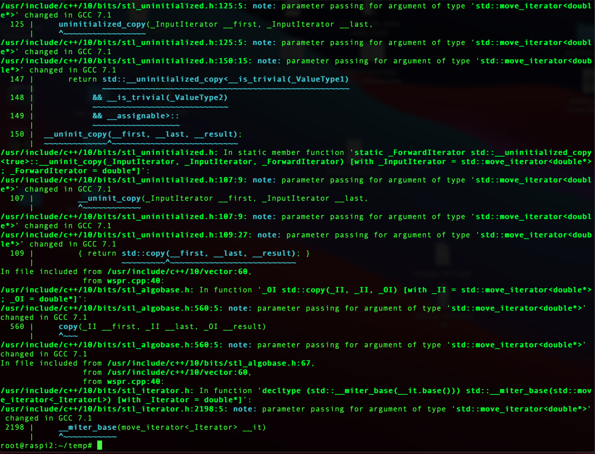
Compiling the code is easy, just run the make command and sit back and watch all the compiler messages scroll across the screen.
make
Compiling the WSPR source code
Once compiled without errors, I just needed to install the binary.
make install
At this point the software is ready to go.
I quickly soldered up a lead to go from the RaspberryPi GPIO pins to the Coax cable that is connected to the EFHW vertical antenna in the garden and connected it all up ready to test.
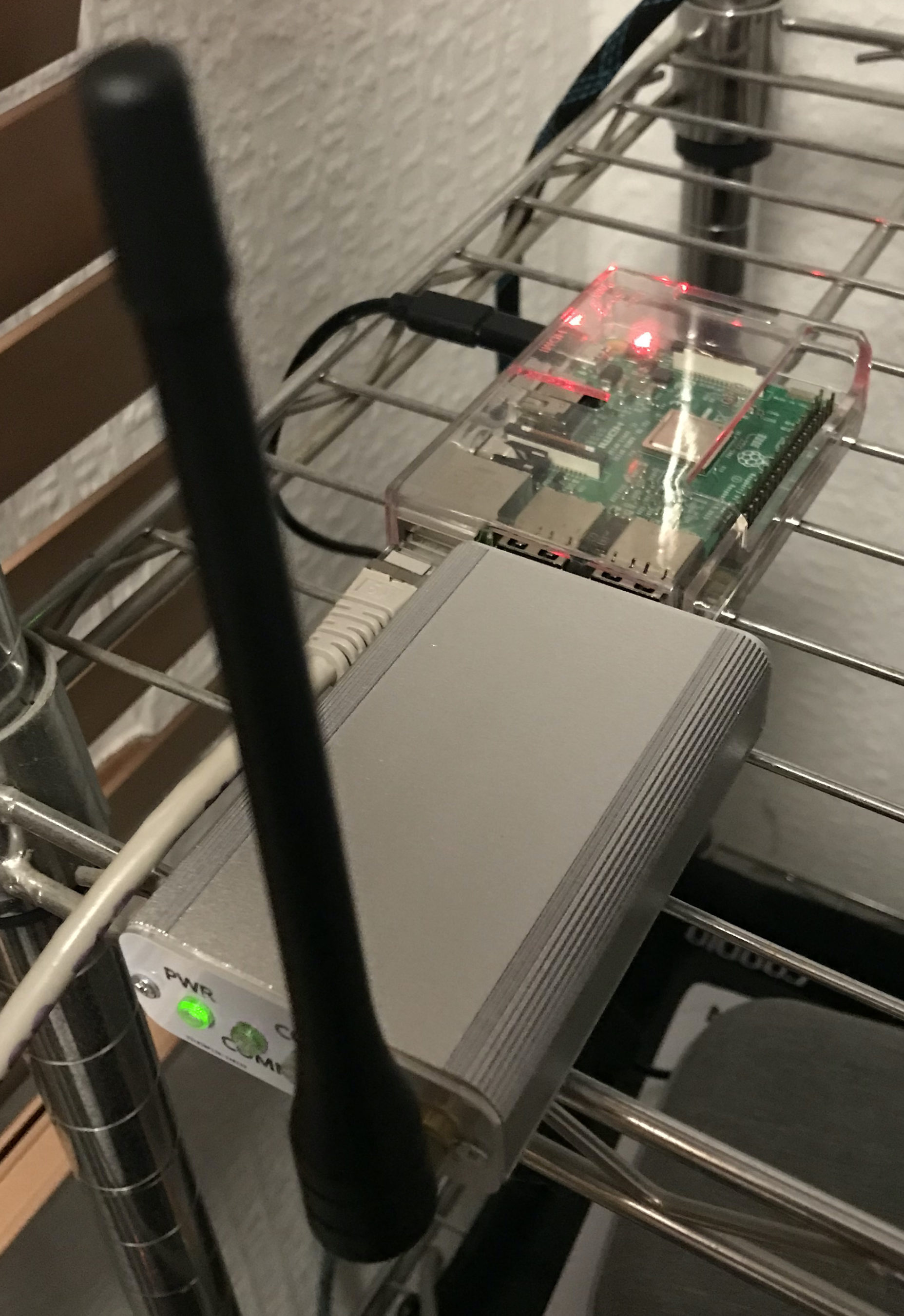
RaspberryPi 2 WSPR Beacon connected to EFHW vertical for 20m/10m bands
Pins 7 and 9 on the Raspberry Pi’s GPIO pins are where the signal is output. Pin 9 is the Ground pin, and pin 7 is the Signal pin. Pin 7 goes to the inner of the coax and pin 9 to the ground side of the coax.
The purple cable is the ethernet cable connecting the Raspi to my local LAN so that I can access it remotely via SSH. I’ve powered the Raspi off of the USB port on the wifi access point in the radio shack which is always on.
Once it’s all connected it’s just a case of starting the WSPR program from the command line as user root.
wspr -s -r M0AWS JO02 10 20m > ./wspr.log &
I run the WSPR program as root user so that it has the correct privileges to access the devices to communicate with the GPIO headers, if you want too start it as your normal user then you’d need to use sudo to gain the root privileges.
The command line options I’ve used are as follows:
-s
Check NTP before every transmission to obtain the PPM error of the crystal
-r
Repeatedly, and in order, transmit on all the specified command line freqs.
M0AWS
My Callsign
JO02
My Locator Square
10
The power being used in dBm
> ./wspr.log &
Redirects all output to wspr.log in the current directory and then puts the program into the background so that it is left running when I log out.
Once the program is started you can monitor progress by using tail on the log file.
tail -f ./wspr.log
The output you will see will be something like this.
Desired center frequency for WSPR transmission: 14.097100 MHz
  Waiting for next WSPR transmission window...
  TX started at: UTC 2022-07-17 16:06:01.015
  TX ended at:   UTC 2022-07-17 16:07:51.638 (110.623 s)
Desired center frequency for WSPR transmission: 14.097100 MHz
  Waiting for next WSPR transmission window...
  TX started at: UTC 2022-07-17 16:08:01.015
  TX ended at:   UTC 2022-07-17 16:09:51.639 (110.624 s)
Desired center frequency for WSPR transmission: 14.097100 MHz
  Waiting for next WSPR transmission window...
  TX started at: UTC 2022-07-17 16:10:01.015
  TX ended at:   UTC 2022-07-17 16:11:51.642 (110.627 s)
Desired center frequency for WSPR transmission: 14.097100 MHz
  Waiting for next WSPR transmission window...
  TX started at: UTC 2022-07-17 16:12:01.015
  TX ended at:   UTC 2022-07-17 16:13:51.639 (110.624 s)
Desired center frequency for WSPR transmission: 14.097100 MHz
  Waiting for next WSPR transmission window...
  TX started at: UTC 2022-07-17 16:14:01.015
  TX ended at:   UTC 2022-07-17 16:15:51.639 (110.624 s)
Desired center frequency for WSPR transmission: 14.097100 MHz
  Waiting for next WSPR transmission window...
  TX started at: UTC 2022-07-17 16:16:01.014
  TX ended at:   UTC 2022-07-17 16:17:51.639 (110.624 s)
Desired center frequency for WSPR transmission: 14.097100 MHz
  Waiting for next WSPR transmission window...
  Obtained new ppm value: 4.09996
  TX started at: UTC 2022-07-17 16:18:01.015
  TX ended at:   UTC 2022-07-17 16:19:51.640 (110.624 s)
Desired center frequency for WSPR transmission: 14.097100 MHz
  Waiting for next WSPR transmission window...
  TX started at: UTC 2022-07-17 16:20:01.014
  TX ended at:   UTC 2022-07-17 16:21:51.638 (110.624 s)
Desired center frequency for WSPR transmission: 14.097100 MHz
  Waiting for next WSPR transmission window...
  TX started at: UTC 2022-07-17 16:22:01.004
  TX ended at:   UTC 2022-07-17 16:23:51.628 (110.624 s)
You can pass multiple bands on the command line if you want to hop around bands.
It’s also recommended that you add a low pass filter between the Raspi and coax connection to help suppress any harmonics that may be generated. You can make one easily enough using just a capacitor or there are a number of prebuilt low pass filters specifically made for the GPIO hat on the Raspi online.
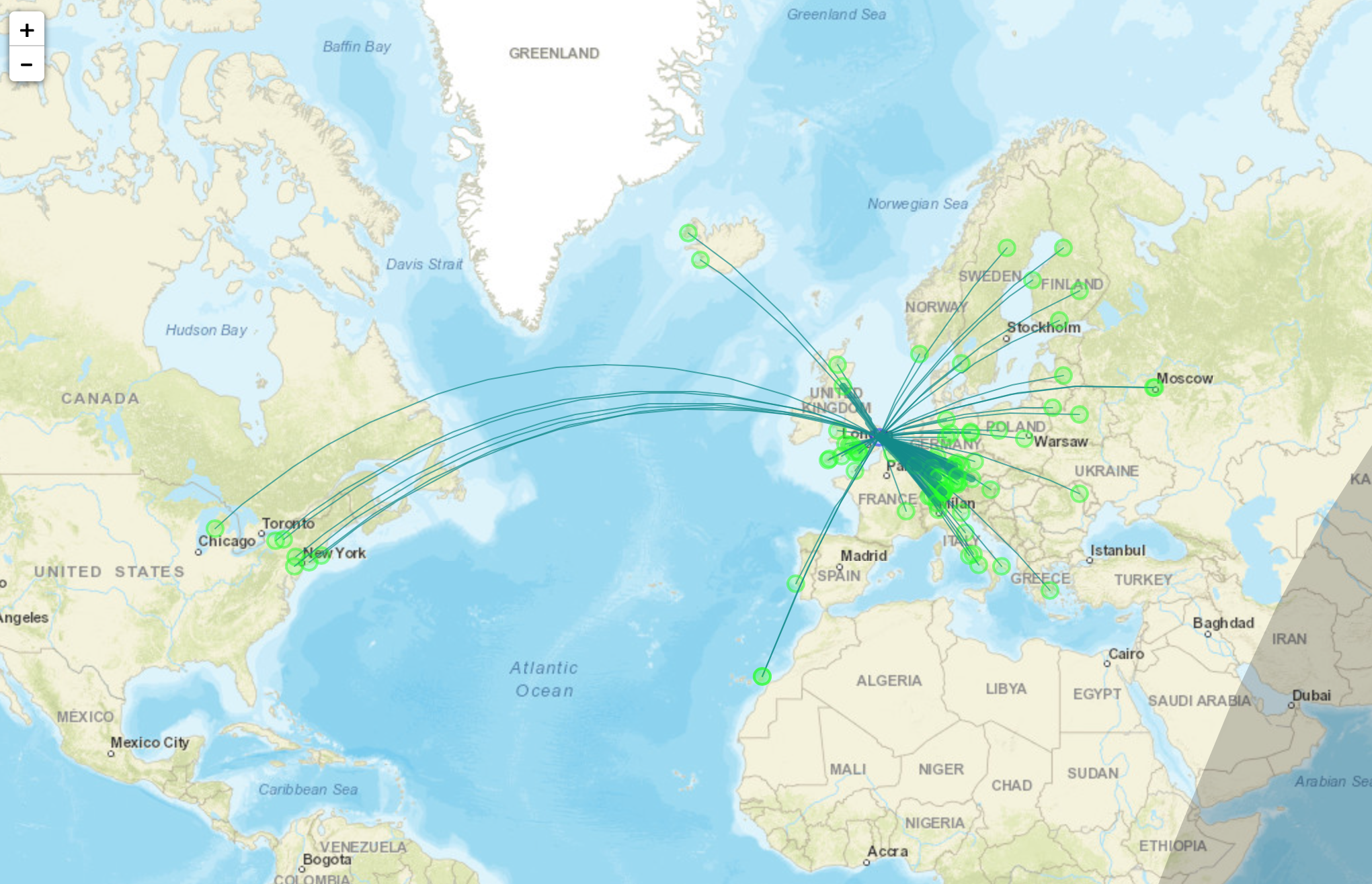
With only 10dBm (10mW) output from the RaspberryPi it’s surprising the distances that the signal travels. In no time at all I had reports from all over Europe and as the day progressed reports started coming in from Iceland, the USA and Russia.
Map showing stations that heard M0AWS on WSPR
I used http://wspr.aprsinfo.com WSPR monitoring website to watch progress as the day went on and after 24hrs had been heard by a number of stations over 3000 miles away.
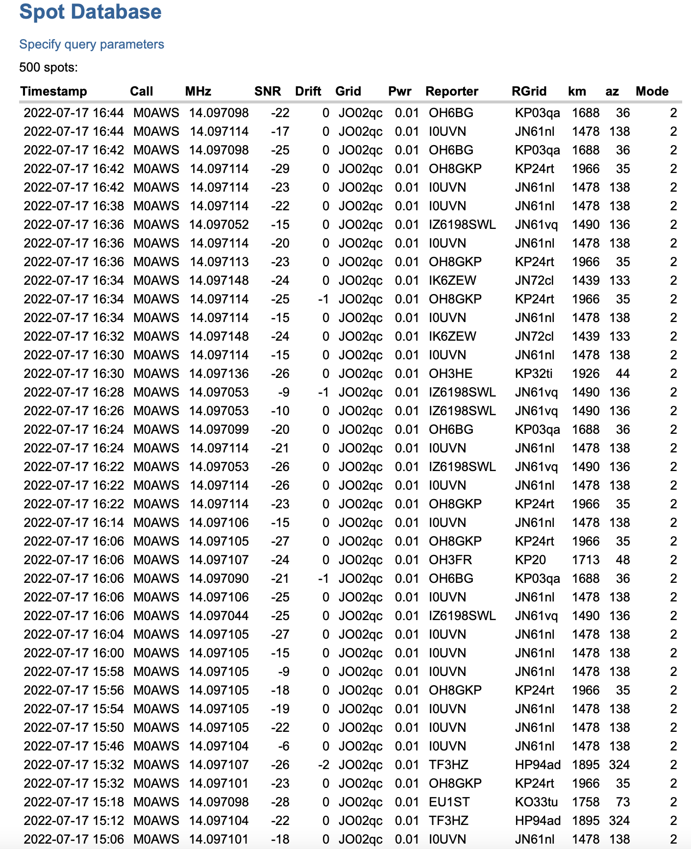
You can also get a more detailed view of reports from the WSPRnet website where you can query the database and create a detailed list of all decodes over a set period of time.
Detailed list of WSPR decodes
Since my EFHW Vertical is resonant on both 20m and 10m I’ll now run it for the next 24hrs on both bands to see what results I get.
More soon …
We use cookies to ensure that we give you the best experience on our website. If you continue to use this site we will assume that you are happy with it.