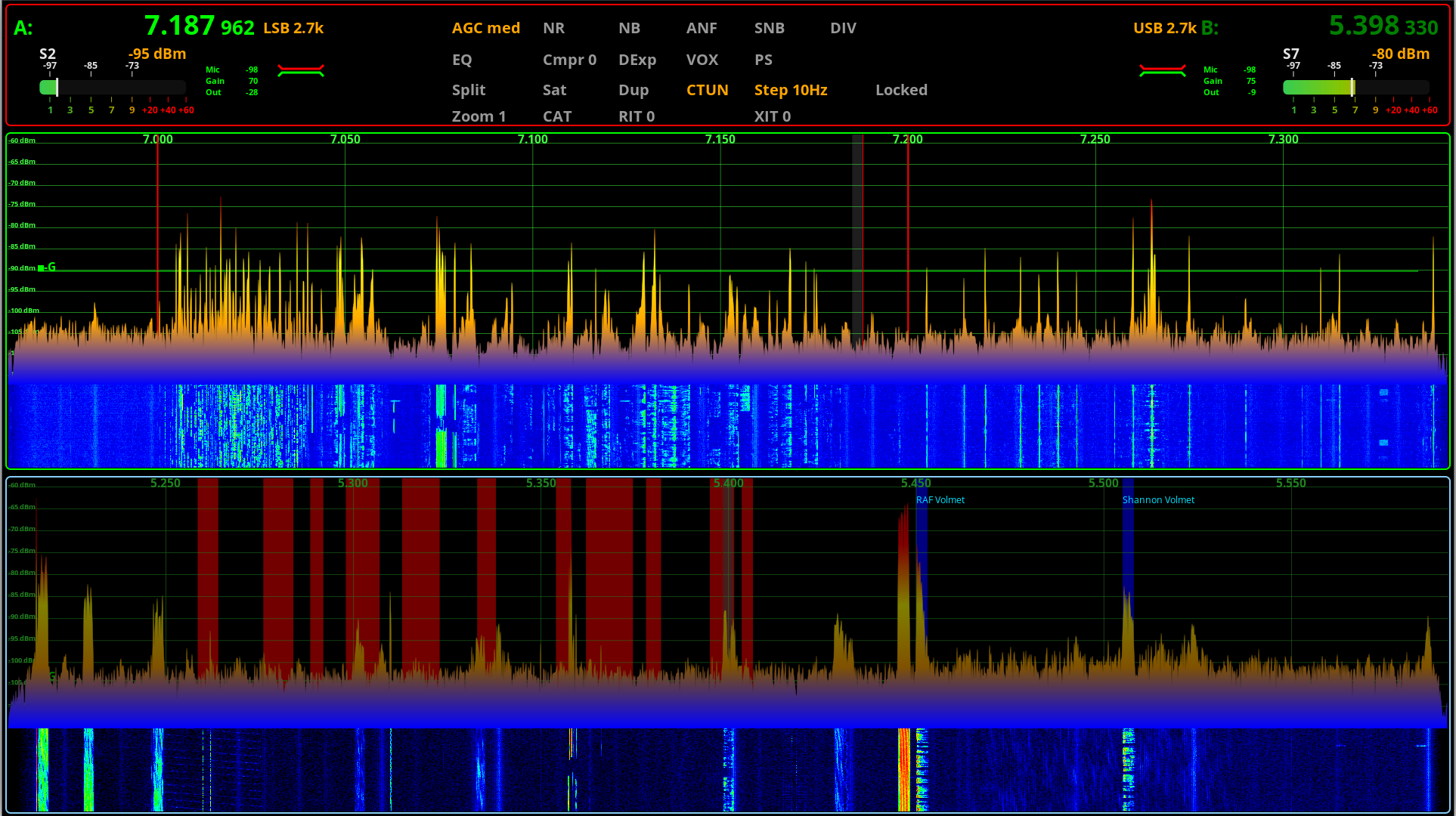
A closer look at my Inverted-L Antenna performance

For some time now I’ve been using an Inverted-L style antenna, albeit not a perfect L but, I have found it to perform extremely well.

When I put the antenna up I was aiming for good NVIS radiation on 80/60/40m for chatting Inter-G and local EU stations <1000 miles from my QTH.

I wasn’t expecting good performance on the higher HF bands as the total length of wire is 37m which is somewhat long for the higher frequency bands however, I’ve found performance around Europe to be very good and extremely good over the north pole to Oceania and the USA.
M0AWS Inverted-L style Antenna

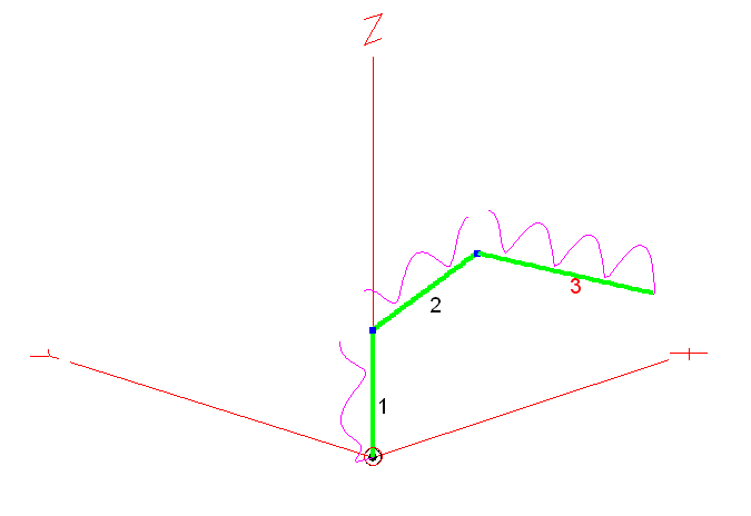
As you can see from the antenna view above, it’s not a perfect inverted-L by any means however, its shape has actually proven to be advantageous.

Wire 1 is 9m tall, it then goes approximately 10.5m in length up to a peak of 12m above ground in the centre, this is where I have a 12m Spiderpole for support. From there the remaining 17.5m of wire slopes down to 5m above ground and is attached to the back of the house via a large insulator. Total wire length is 37m.

Wire 1 is at the bottom of a South facing garden and direction +X is north.

The antenna is tuned at the bottom of wire 1 using my CG3000 Remote Auto ATU at ground level. There are a number of random length radials hidden in the lawn and around the perimeter of the garden running mainly from South to North. I cannot run any radials to the south (-X) as this is farmland and not owned by me.

The radio I use is a Hermes Lite 2 SDR paired with a Xiegu XPA125B 100w amplifier. I normally only use 80w or less on all bands and so, my results are achievable using any 100w radio.

On the low bands I find it has great NVIS performance with excellent signal reports from all over the UK and out to around 1500 miles into Europe and beyond. This is exactly what I wanted from the antenna and I’ve been very pleased with it’s performance on 80/60/40m.

Looking at the 2D Far Field Plots on the 3 low bands the antenna has a typical NVIS high angle of radiation pattern with some gain.
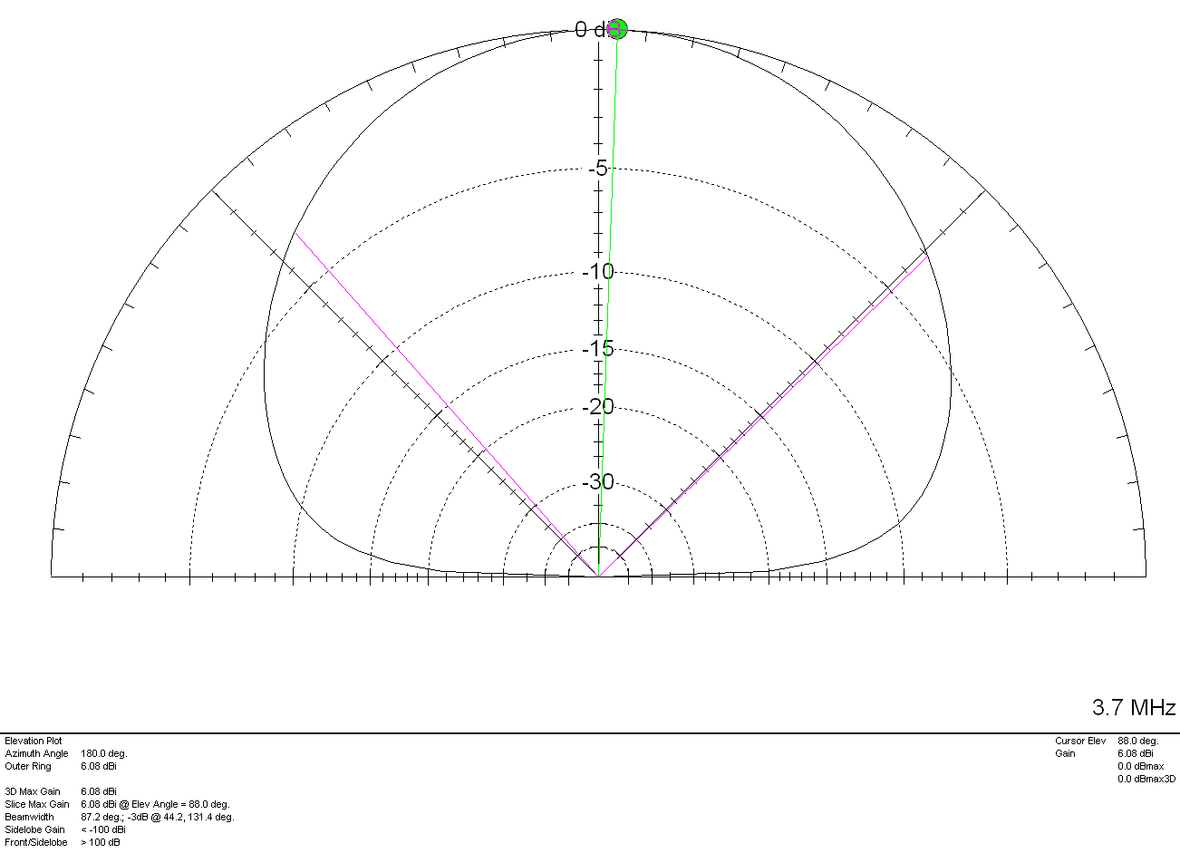
M0AWS Inverted-L Style Antenna 2D Plot on the 80m Band

On the 80m band maximum radiation is straight up, as expected with a gain of 6.08dBi (3.58dBd). The gain reduces at lower angles however, it still performs well out to around 1500 miles and occasionally even further.
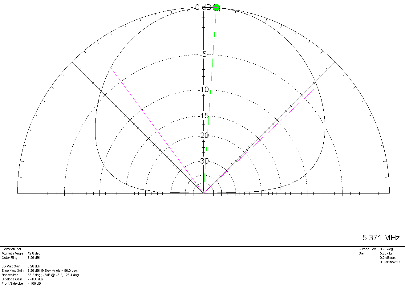
M0AWS Inverted-L Style Antenna 2D Plot on the 60m Band

Once again on the 60m band maximum radiation is pretty much straight up as expected however, I have worked in to Canada many times on 60m with excellent signal reports and so, it also has good DX capability too. With 5.26dBi (2.76dBd) gain it’s not a lossy antenna by any stretch of the imagination.
M0AWS Inverted-L Style Antenna 2D Plot on the 40m Band

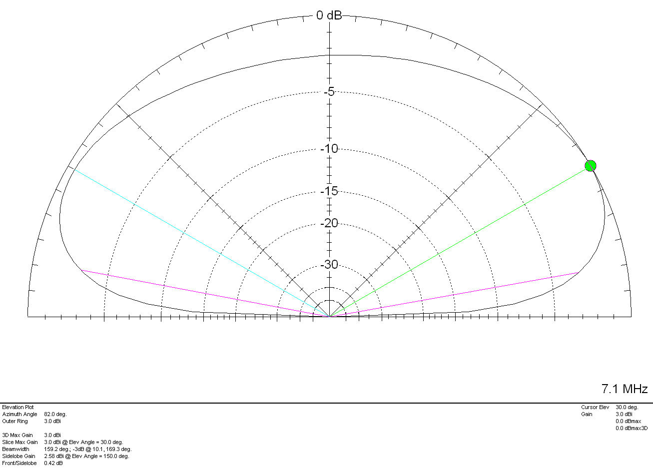
On the 40m band things start to change a little with the angle of maximum radiation being at 30 degrees rather than straight up. This gives the antenna “longer legs” on the 40m band making it very easy to work longer distances. It’s still very good for Inter-G but, performance over longer distances is considerably better. With a gain of 3.0dBi (0.5dBd) it’s performance is similar to that of a dipole at a similar height above ground.

Above 7Mhz things start to change considerably. The antenna becomes directional to the North West (NW) and North East (NE) giving excellent DX results over the North Pole into North America and Australia/New Zealand. The antenna does of course also have an element of high angle radiation making it useful into Europe and North Africa on the higher bands.
M0AWS Inverted-L Style Antenna 2D Plot on the 20m Band

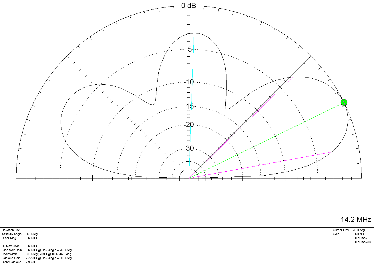
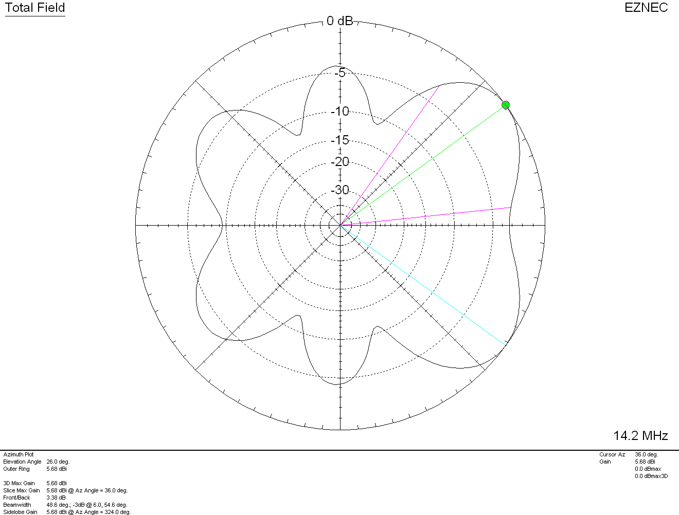
On the 20m band the maximum radiation is at 26 degrees with a gain of 5.68dBi (3.18dBd) pointing NW and NE. There is a lower gain lobe to the South West (SW) and South East (SE) giving excellent coverage through Europe and into Africa as can be seen in the 3D Far Field Plot and Azimuth Slice shown below.
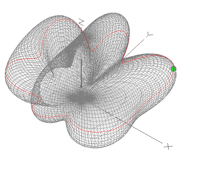
M0AWS Inverted-L Style Antenna 3D Plot on the 20m Band
M0AWS Inverted-L Style Antenna 2D Azimuth Slice on the 20m Band

Moving up in frequency to the 17m band the 3D Plot and Azimuth Slice are similar to that on the 20m band but, with a slightly lower angle of maximum radiation and slightly more gain as can been in the 2D elevation plot shown below.
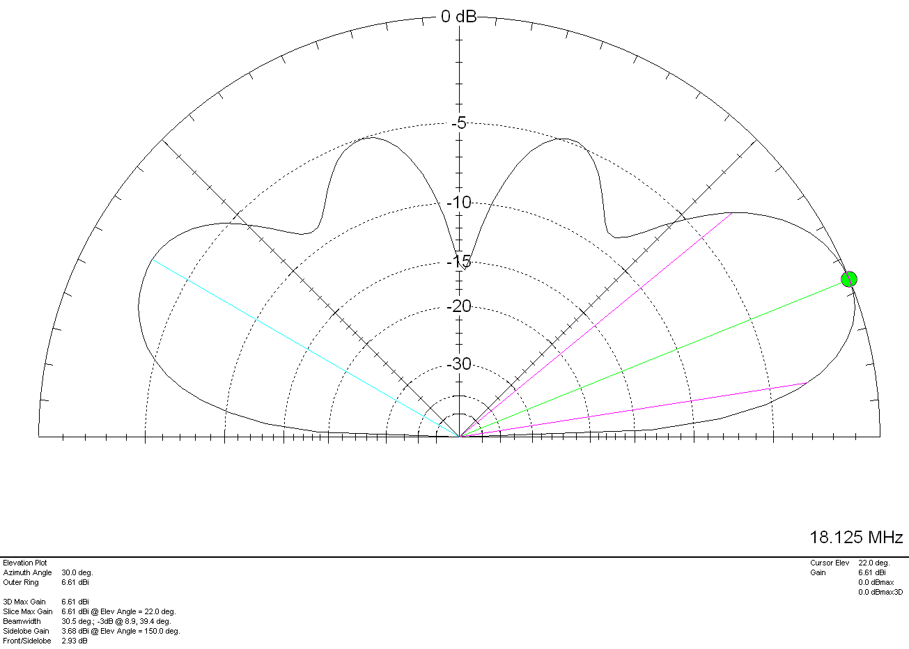
M0AWS Inverted-L Style Antenna 2D Plot on the 17m Band

With a gain of 6.61dbi (4.11dBd) at 22 degrees to the NW and NE and slightly lower gain and higher angle to the SW and SE the antenna has proven to work extremely well on the 17m band. My best DX on 17m so far has been a QSO with Eric, FK8GM in New Caledonia some 10230 miles from my QTH using just 80w of SSB.

The 15m band is a similar story, 7.6dBi (5.1dBd) at just 18 degrees pointing NW and NE. This antenna works extremely well into North America and Oceana (I’ve also worked FK8GM on 15m too). Once again there are lower gain lobes to the SW and SE at a similar angle along with some high angle radiation that aids coverage into Europe. The antenna really is a great all rounder on the 15m band.
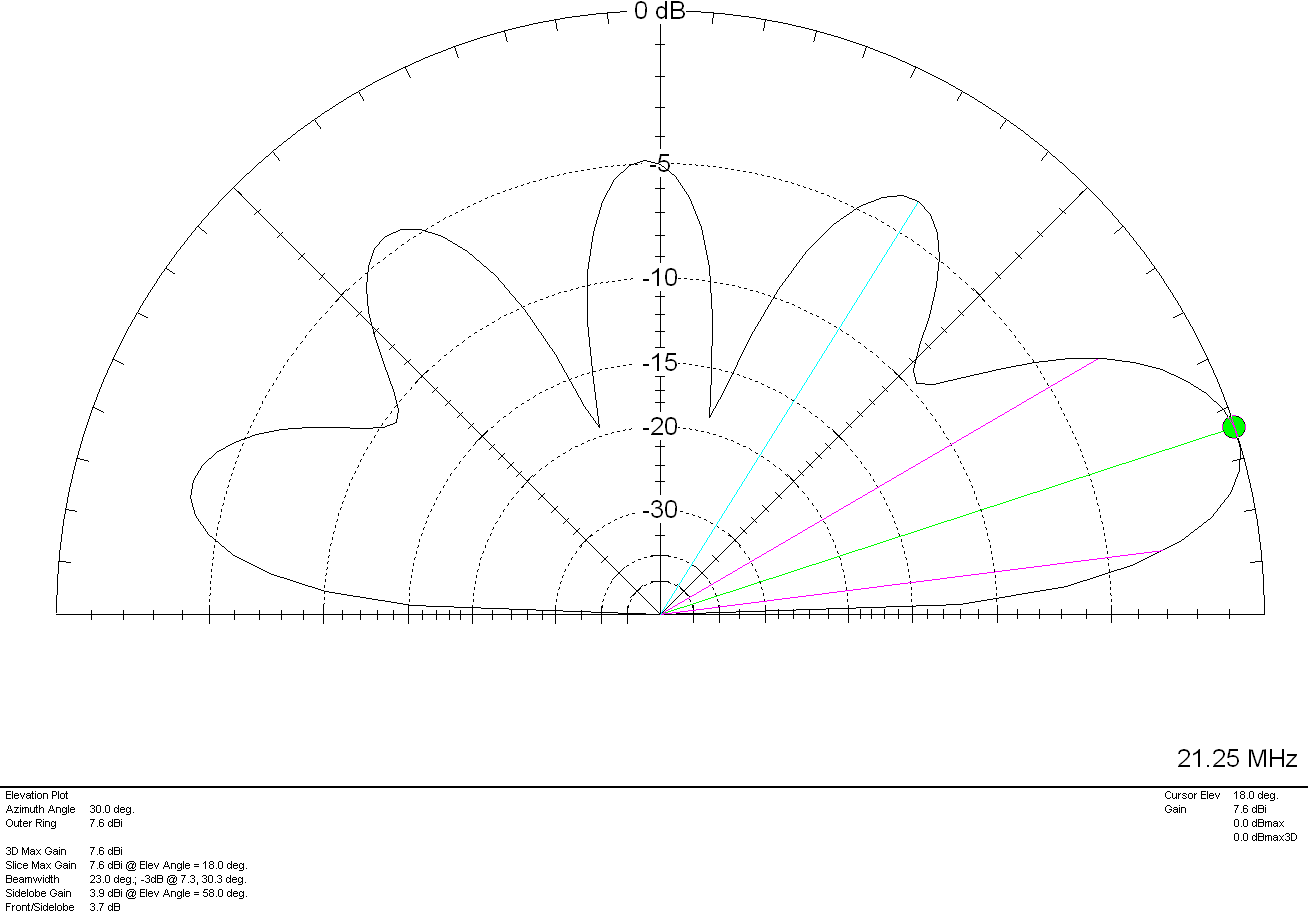
M0AWS Inverted-L Style Antenna 2D Plot on the 15m Band

The 12m and 10m bands are a similar story, low angle, high gain lobes to the NW and NE with lower gain coverage to the SW and SE.
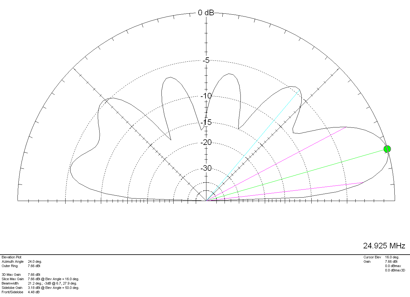
M0AWS Inverted-L Style Antenna 2D Plot on the 12m Band

On 12m the antenna has a very respectable gain of 7.66dBi (5.16dBd) at a low 16 degrees pointing NW and NE making it a great DX antenna. Once again, higher angle lower gain lobes to the SW and SE.

Finally on the 10m band the antenna has a gain of 6.96dBi (4.46dBd) at a very low angle of 14 degrees to the NW and NE. If DXing over the pole on the 10m band is your thing then this simple antenna will certainly help you along and maybe even put a smile on your face.
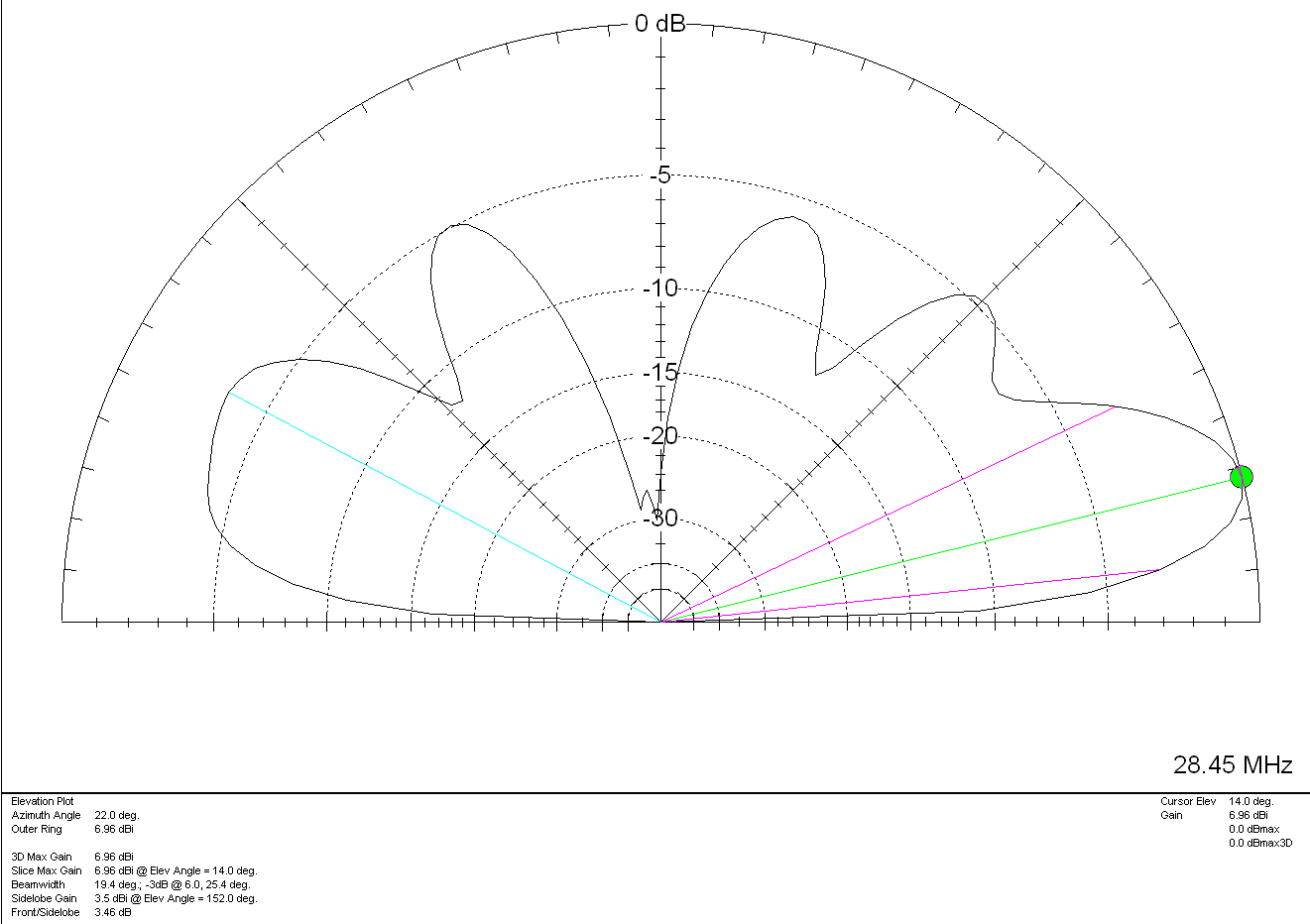
M0AWS Inverted-L Style Antenna 2D Plot on the 10m Band

For such a simple antenna that will fit easily into many typical UK gardens I have been extremely pleased with it’s performance. Whether I’m gassing on the low bands with friends from the Matrix rooms or chasing DX on the higher bands, the antenna has put a smile on my face time and time again.

On receive the antenna is surprisingly quiet, with an S3-4 background noise on the 80/60/40m bands through to less than 1 S point of noise on the higher bands. Picking out the weak DX stations really isn’t a problem.

It just goes to show that you don’t need to spend a fortune on commercial antennas to work the world on the HF bands. With as little as 80w of SSB and a piece of wire connected to a remote ATU you can have just as much fun as the big boys!

More soon …
Dual Band VHF/UHF End Fed Vertical Dipole

Since purchasing my Icom IC-705 radio I’ve only used it on the HF bands. Since the IC-705 is a “shack-in-a-box” I thought it was about time I ventured up onto the VHF/UHF bands and add another string to my bow.

Since I don’t have an antenna for these two bands I’d need to build something. I’m not really interested in DXing on the VHF/UHF bands as I’d need a yagi or two, a rotator and would need to get the entire setup up high on the chimney on the house.

We’re very fortunate in that there are a good many repeaters on VHF/UHF in East Anglia with quite a few being well within range of my QTH.

So I decided to go with a simple vertical antenna of some sort that I could easily attach to the top of a 10m spider pole and pop up in the garden without too much hassle.

The simplest of all antennas to build for any band is an end fed vertical dipole. It’s made purely from a piece of coax cable, you can’t get much simpler.

Using some dimensions I found online I unrolled a length of RG58U and set about cutting it to resonance for the two bands.

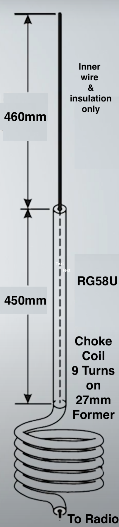
To start I measured out 910mm of RG58U and put a piece of tape around the cable at the 910mm point. I then stripped the top 460mm of the outer and braid from the coax so that the inner wire and plastic insulation was exposed. This then left 450mm of coax with the braid still in place to make up the 2nd half of the vertical dipole.

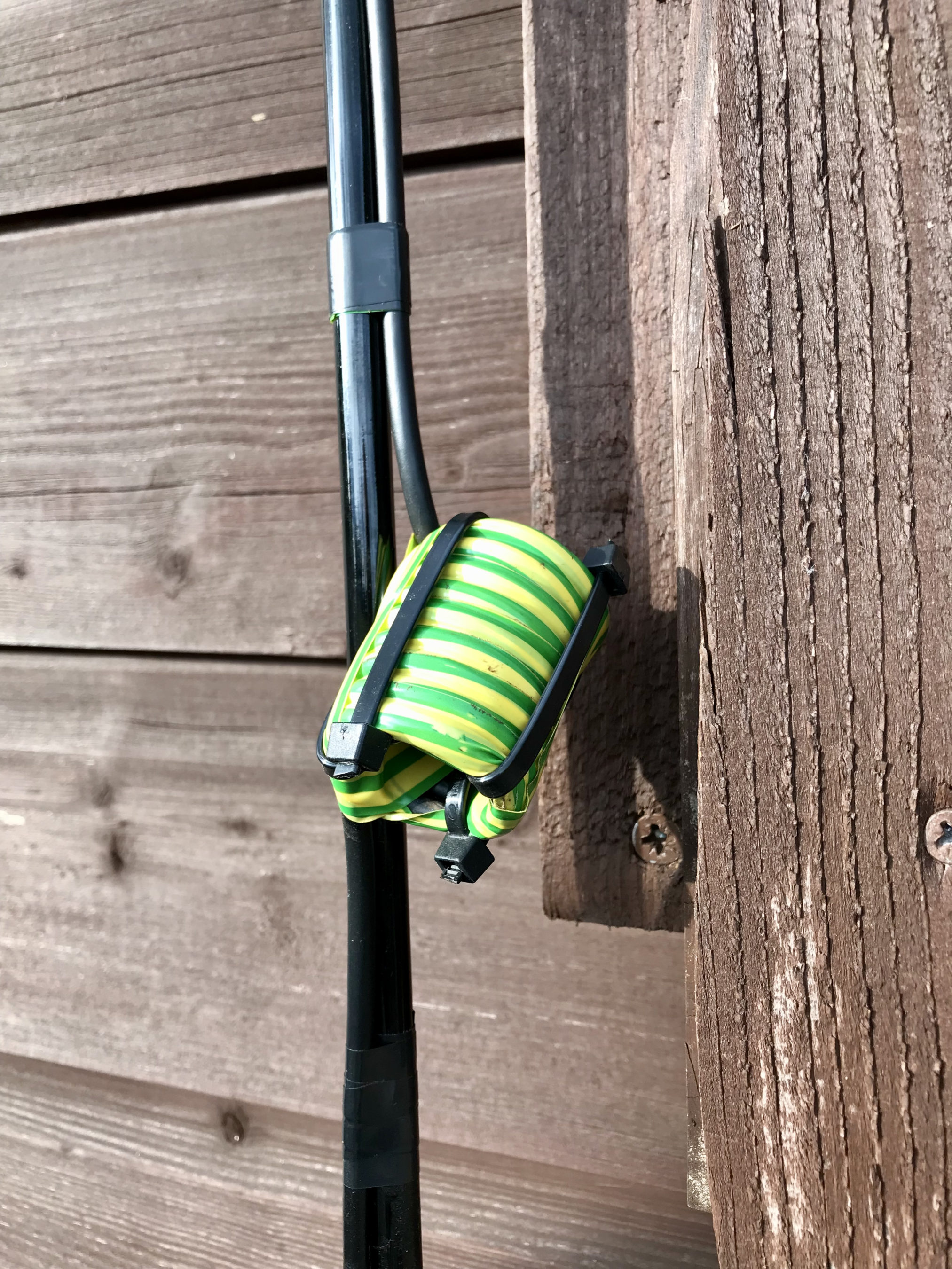
At the 910mm marker I wound the coax 9 times around a 27mm former to create a choke balun. I taped the coil up to ensure it kept it’s shape, removed it from the former and then used a few zip ties to hold it in place.

VHF/UHF End Fed Vertical Dipole Diagram

The diagram above aids in visualisation of the make up of the antenna that is made from a single piece of RG58U coax cable.

Choke Balun made from 9 turns of RG58U on a 27mm former

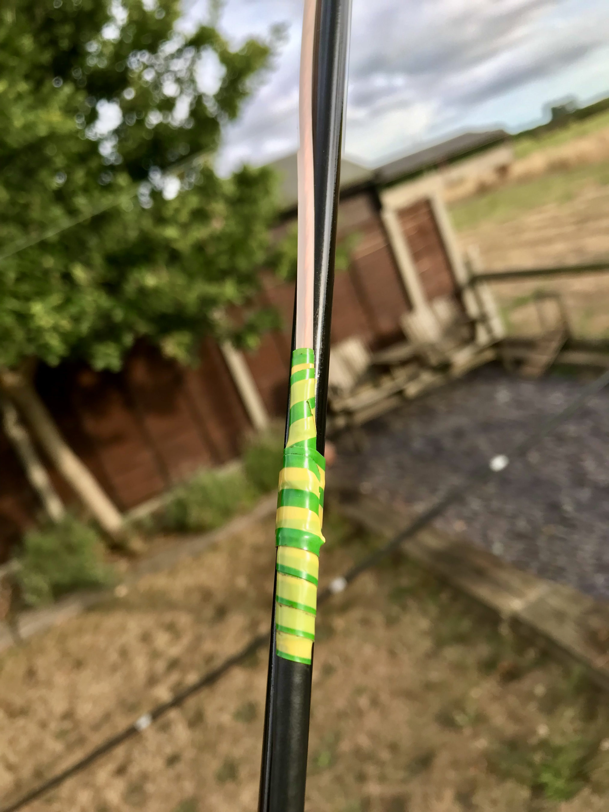
I next wound some electrical tape around the point on the antenna where the outer insulation and braid ended so that it would stop moisture getting into the rest of the coax and causing problems in the future. I also put a bit of electrical tape across the top of the end of the wire to stop moisture getting into the inner wire and then a piece of electrical tape around the wire to ensure it was fully sealed.

Electrical tape wound around the point where the outer braid finishes

At this point the antenna was complete! It literally took a few minutes to make. I could now either cut the coax a few centimetres from the bottom of the coil and fit a PL259 or just continue the coaxial cable back into the shack and fit a PL259 on the end. I decided to go with the latter as it’s one less connection to make.

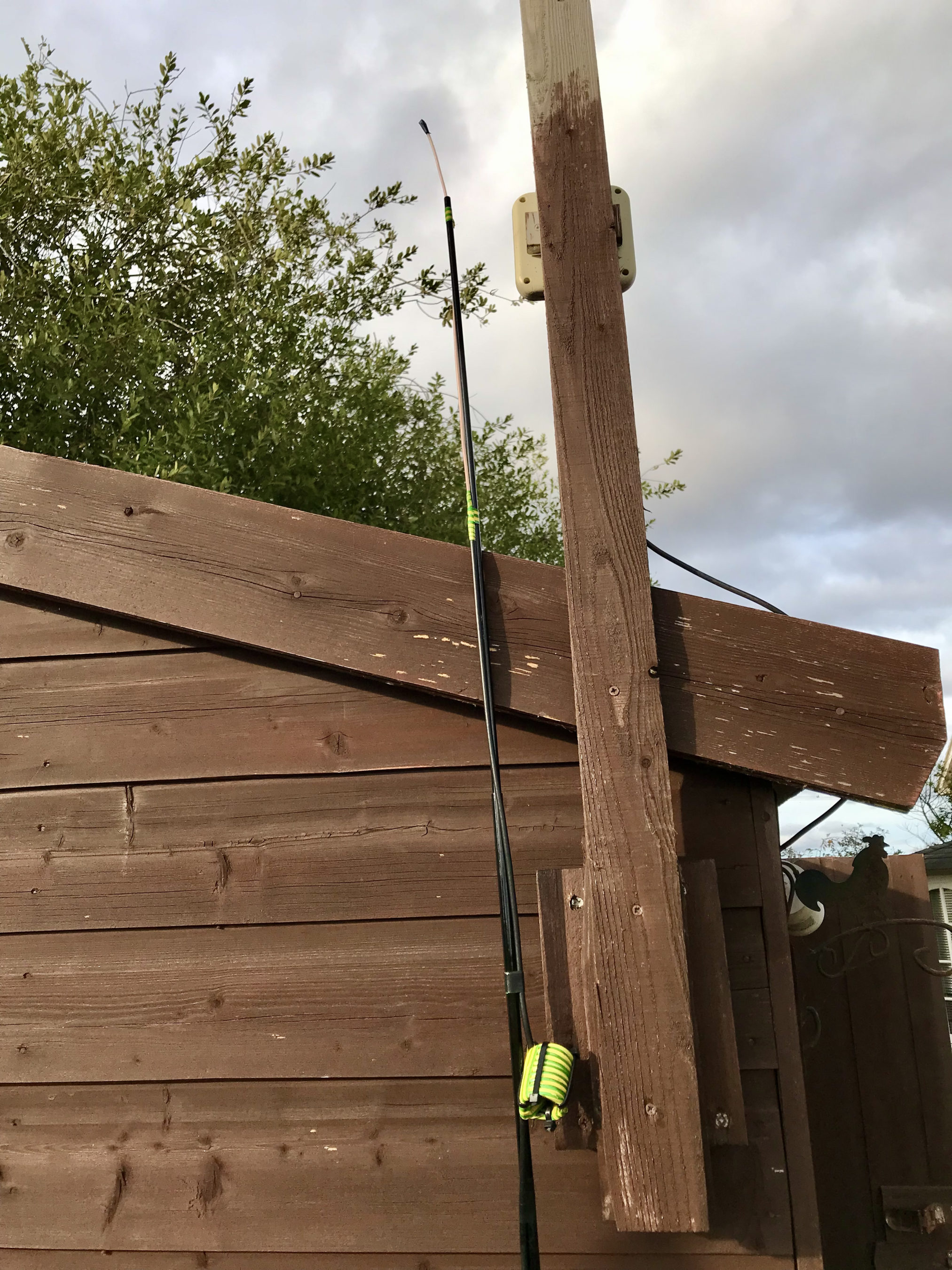
VHF/UHF End Fed Vertical Dipole taped to the top of a 10m spiderpole

Once complete, I taped the antenna to the top of a 10m spider pole and then ran the rest of the coax back into the shack and soldered on a PL259 connector.

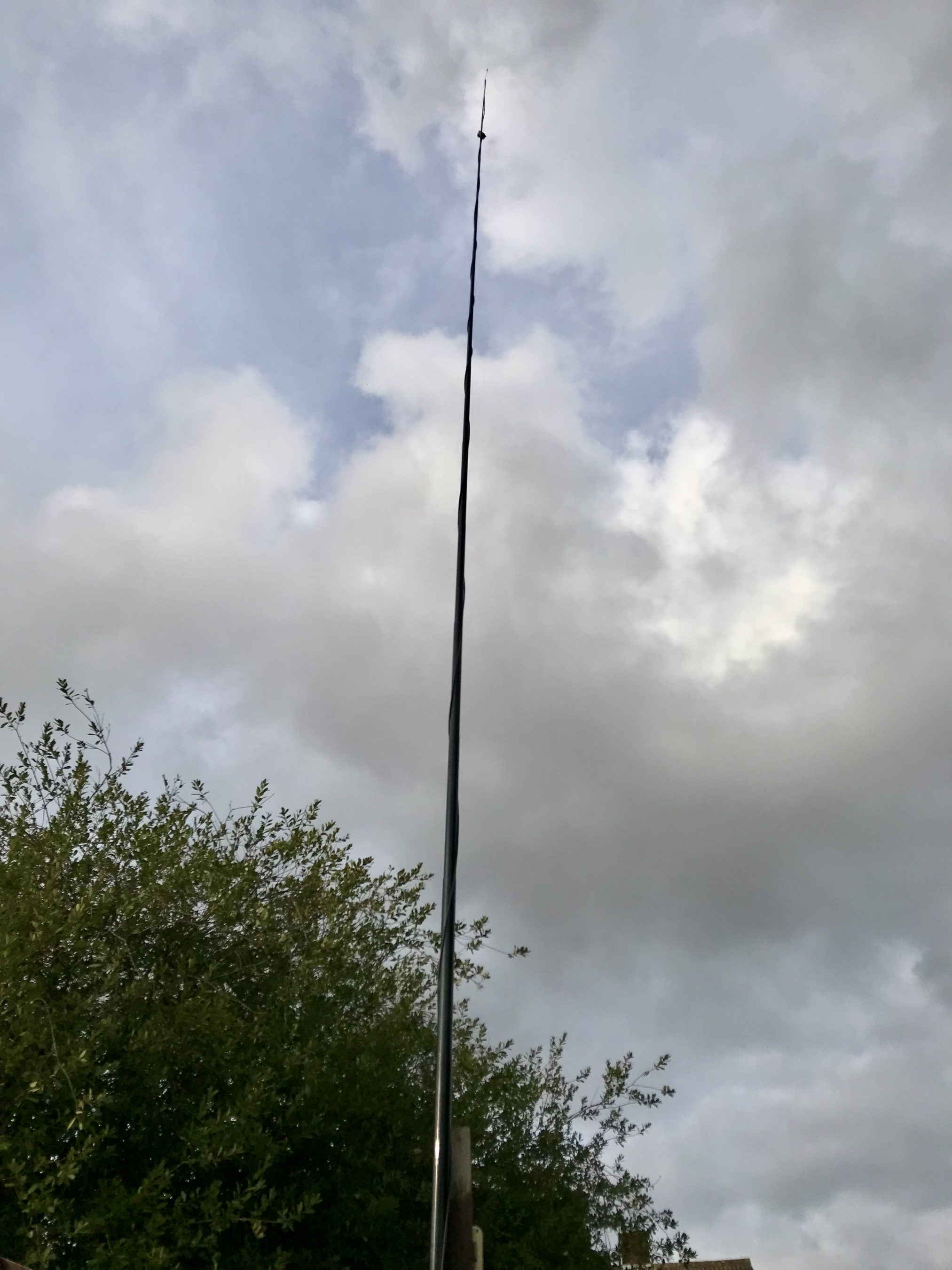
Raising the spider pole up to its maximum length put the antenna some 10m up above the ground. Hopefully this will give me a relatively clear path to the local repeaters.

Plugging the antenna into the IC-705 and checking the SWR I found it was <1.2:1 across the entire 2m band and <1.5:1 across most of the 70cm band. It was perfect for what I wanted!

VHF/UHF End Fed Vertical Dipole up 10m on a Spiderpole

I configured the local repeaters into the the IC-705 memories so that I could easily switch from one repeater to the next with all the appropriate tone and duplex frequency shifts set at the touch of a button.

My local 2m repeater GB3PO comes in at 5/9+10dB without any preamp and the local 70cm repeater GB3IH comes in at 5/9+5dB without any preamp. I was really pleased with the results and set about having a chat with other local HAMs on the local repeaters. It’s been a while since I’ve used the mic on this radio and it made a nice change!

To my surprise I found I could get into far more repeaters than I ever imagined. GB3NB in Norwich is 5/8 as are a number of repeaters down in Essex. This gives me quite a scope for chatting on the VHF/UHF bands via the repeater network.

To my surprise I can also hear ON0WV in Brugge Belgium, unfortunately it’s on the same frequency as the local 2m GB3PO repeater and so often gets drowned out completely but, it’s good to know that when there’s a lift in propagation I should be able to get into the near continent without too much hassle.

If you’re looking to build a simple but, effective 2m/70cm vertical for local repeater access then I highly recommend making an end fed vertical dipole. It only takes a few minutes to cut the cable to length, remove the outer sheath and braid and wind the choke balun, it really couldn’t be any easier.

More soon …