QO-100 Satellite Ground Station Complete Build

I get quite a few emails from readers of my blog asking how my QO-100 satellite station is put together and so, I thought perhaps now is a good time to put together an article detailing the complete build.

My QO-100 satellite ground station is built around my little Icom IC-705 QRP transceiver, it’s a great little rig and is ideal for the purpose of driving a 2.4Ghz transverter/up-converter.

Of course all the software used for the project is Opensource and freely available on the internet.

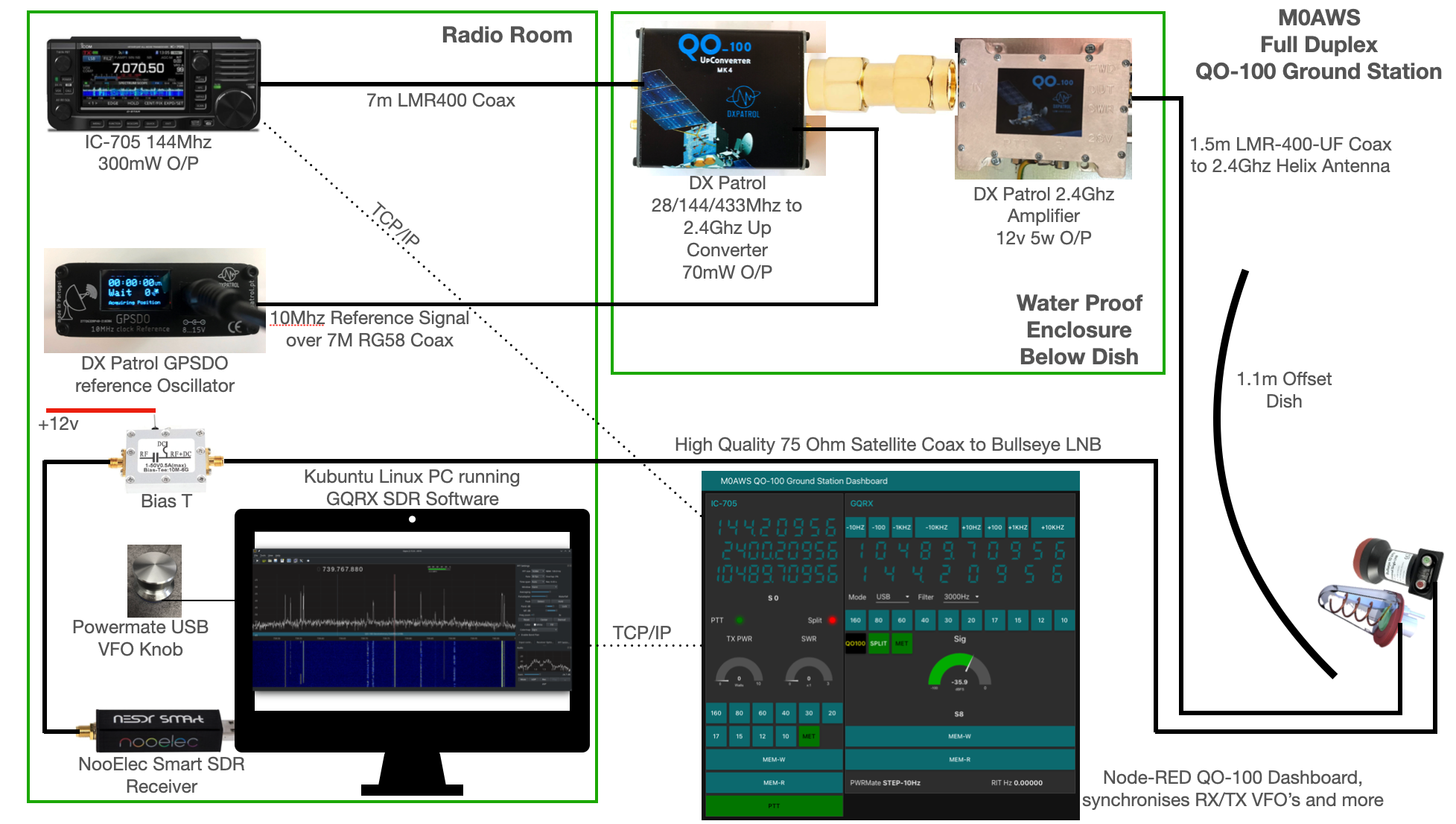
M0AWS QO-100 Ground Station Build Visual
M0AWS QO-100 Ground Station Build Visual (Click to Enlarge)

The station comprises of the following building blocks:

  • Icom IC-705 Transceiver
  • DXPatrol 28/144/433Mhz to 2.4Ghz Up-Converter
  • DXPatrol GPSDO Reference Oscillator
  • DXPatrol 2.4Ghz 5/12w Amplifier
  • Nolle Engineering 2.2 turn 2.4Ghz IceCone Helix Antenna
  • 1.1m (110cm) Off-set Dish
  • Bullseye 10Ghz LNB
  • Bias-T to feed 12v to LNB
  • NooElec SmartSDR Receiver
  • PC Running Kubuntu Linux Operating System
  • GQRX SDR Opensource Software
  • Griffin Powermate USB VFO Knob
  • QO-100 Ground Station Dashboard developed using Node-RED
  • LMR400-UF/RG58 Coax Cable
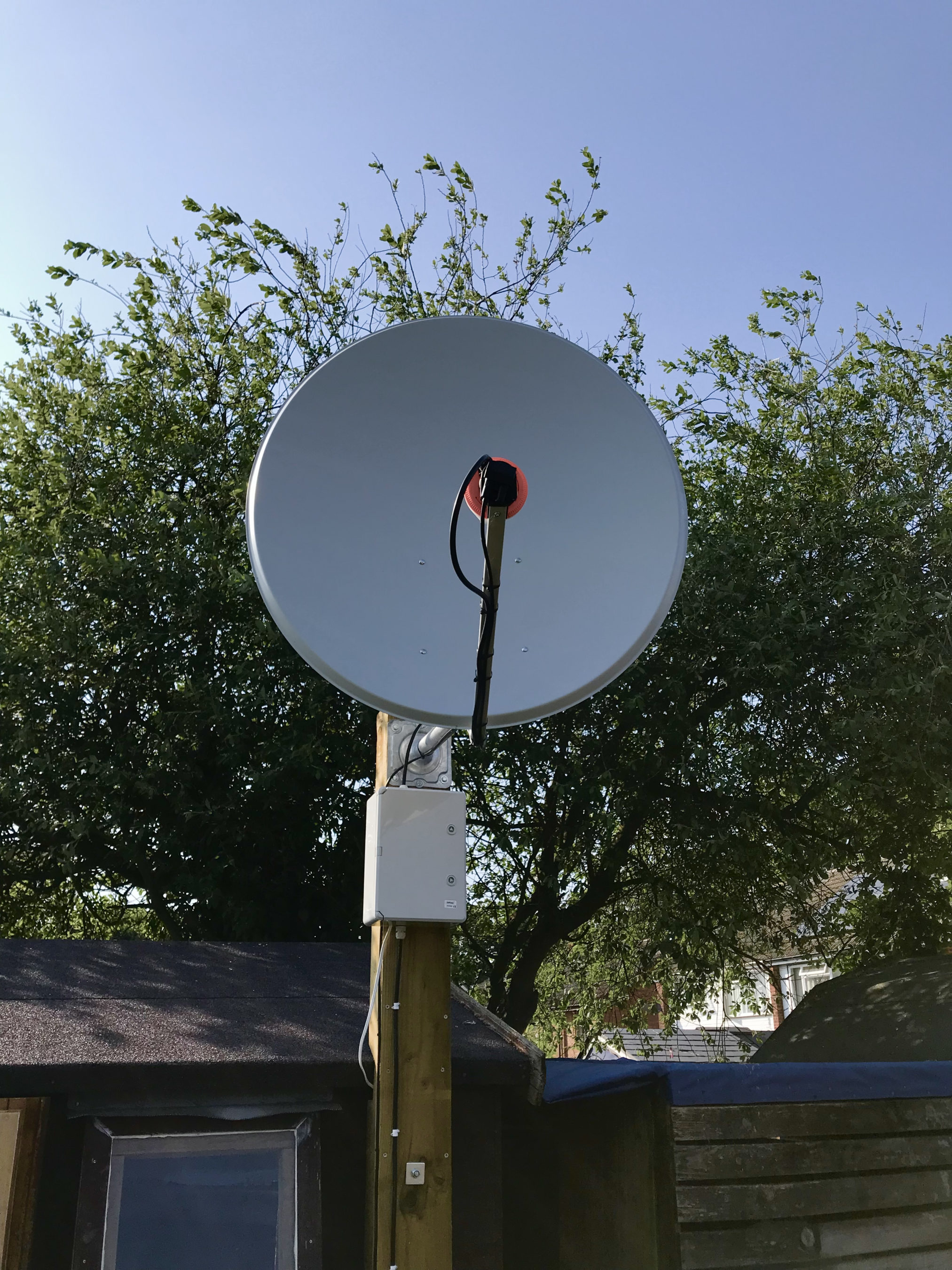
M0AWS QO-100 1.1m off-set Dish and IceCone Helix antenna ground station
M0AWS QO-100 1.1m (110cm) off-set Dish with IceCone Helix antenna and Bullseye LNB.

To get a good clear view of the QO-100 satellite I have the dish mount 3.2m above the ground. This keeps it well clear of anyone walking past in the garden and beams the signal up at an angle of 26.2 degrees keeping well clear of neighbouring gardens.

The waterproof enclosure below the dish houses all the 2.4Ghz equipment so that the distance between the feed point and the amplifier are kept to a minimum.

The DXPatrol amplifier is spec’d to run at 28v/12w or 12v/5w, I found that running it at 28v produced too much output for the satellite and would cause the LEILA alarm on the satellite to trip constantly. Running the amp at 12v with a maximum of 5w output (average 2.5-3.5w) is more than enough for me to have a 5/9+10 signal on the transponder.

The large 1.1m dish gives me quite an advantage on receive enabling me to hear the very weak stations with ease compared to other stations.

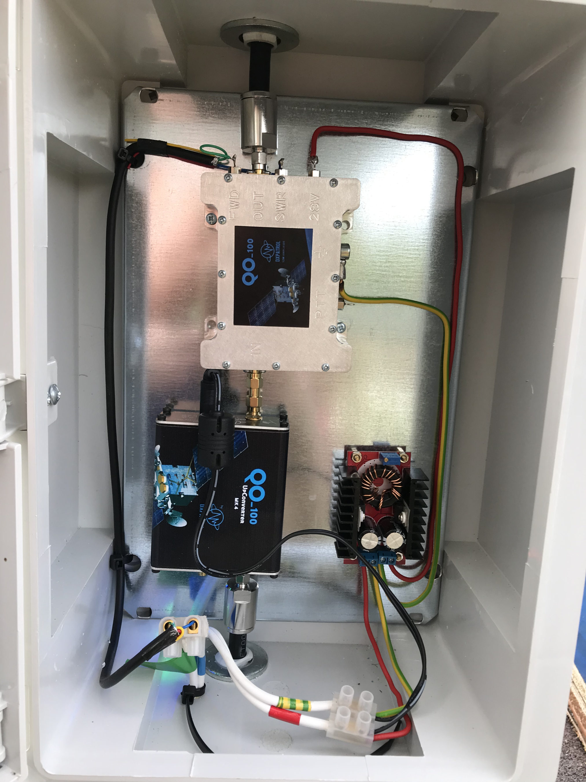
2.4Ghz ground station enclosure ready for testing

The photo above shows the 2.4Ghz equipment mounted in the waterproof enclosure below the dish. This photo was taken during the initial build phase before I rewired it so, the amplifier is shown connected to the 28v feed. To rewire the amp to 12v was just a matter of removing the 28v converter and connecting the amp directly to the 12v feed instead. This reduced the output from a maximum of 12w down to a maximum of 5w giving a much better (considerate) level on the satellite.

It’s important to keep all interconnects as short as possible as at 2.4Ghz it is very easy to build up a lot of loss between devices.

For the connection from the IC-705 to the 2.4Ghz Up-Converter I used a 7m run of
LMR-400 coax cable. The IC-705 is set to put out just 300mW on 144Mhz up to the 2.4Ghz converter and so it’s important to use a good quality coax cable.

Once again the output from the 2.4Ghz amplifier uses 1.5m of LMR-400-UF coax cable to feed up to the 2.2 turn Icecone Helix Antenna mounted on the dish. This keeps loss to a minimum and is well worth the investment.

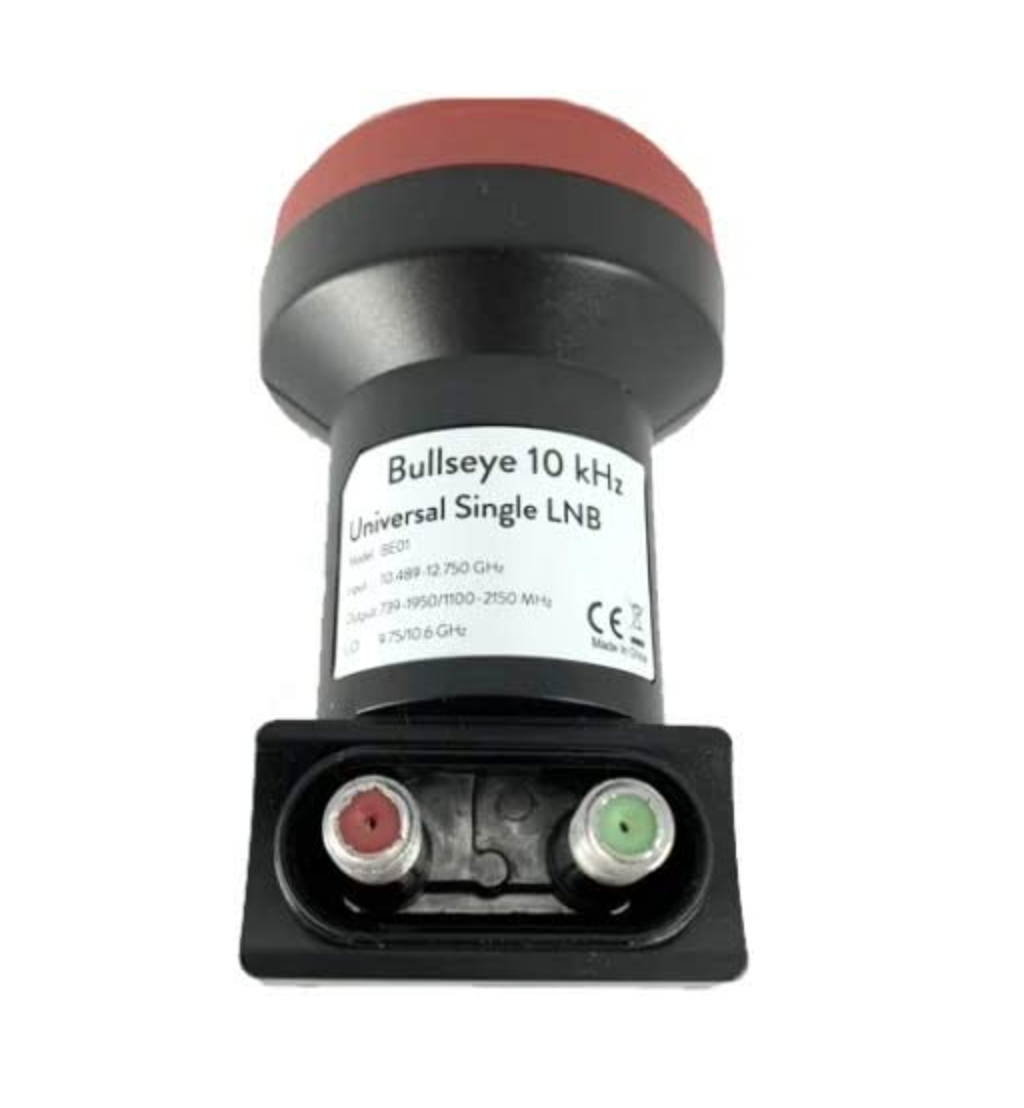
Bullseye 10Khz High Stability Unversal Single LNB for 10.489-12.750Ghz

The receive path starts with a Bullseye LNB, this is a high gain LNB that is probably one of the best you could use for QO-100 operations. It’s fairly stable frequency wise but, does drift a little in the summer months with the high temperature changes but, overall it really is a very good LNB.

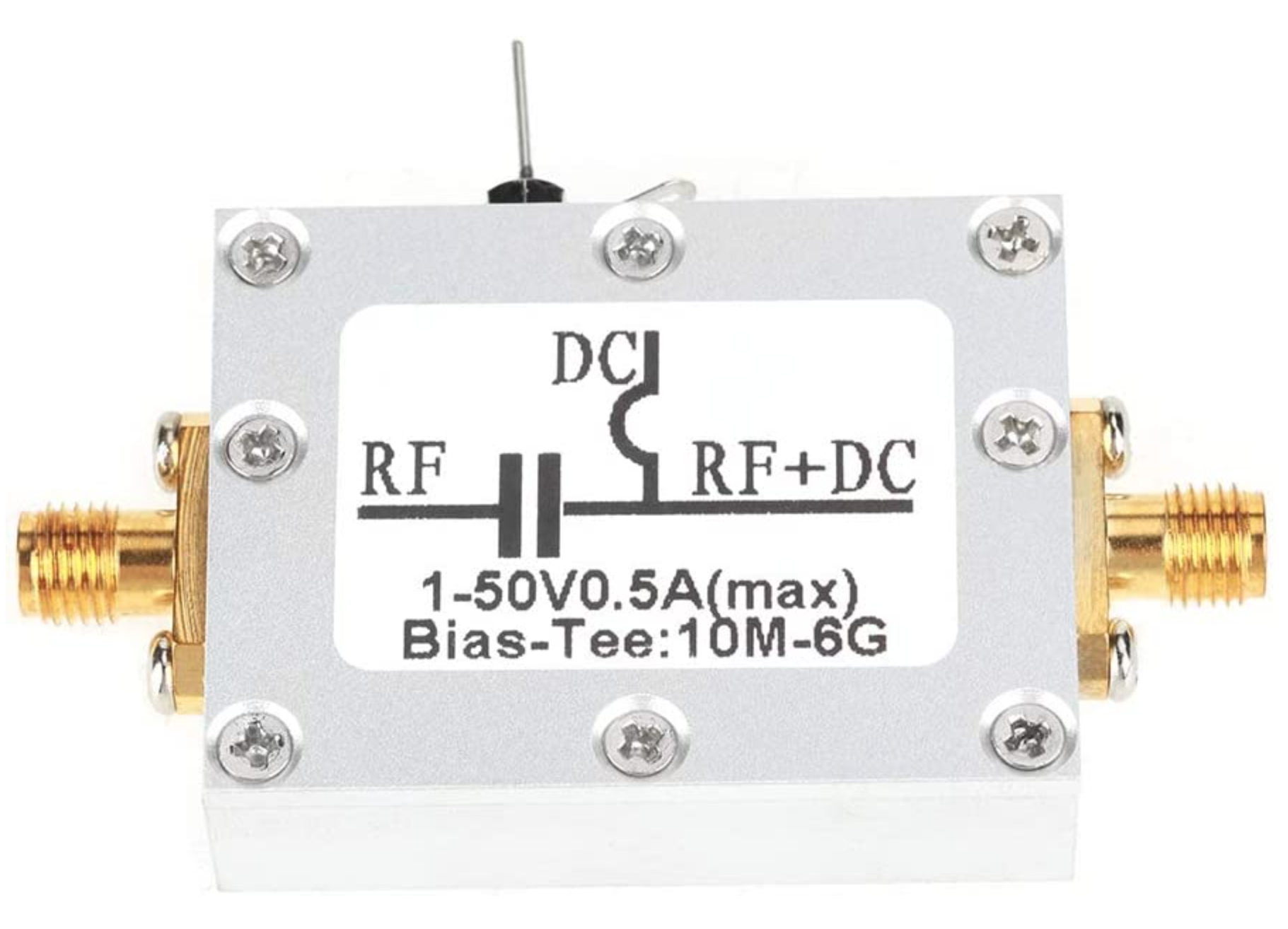
The 12v feed to the LNB is via the coax and is injected by the Bias-T device that is in the radio shack. This 12v feed powers the LNA and associated electronics in the LNB to provide a gain of 50-60dB.

Bias-T to inject 12v feed into the coax for the Bullseye LNB

From the Bias-T the coax comes down to the NooElec SmartSDR receiver. This is a really cheap SDR device (<£35 on Amazon) based on the RTL-SDR device but, it works incredibly well. I originally used a Funcube Dongle Pro+ for the receive side however, it really didn’t handle large signals very well and there was a lot of signal ghosting so, I swapped it out for the NooElec SDR and haven’t looked back since.

The NooElec SmartSDR is controlled via the excellent Opensource software GQRX SDR. I’ve been using GQRX SDR for some years now and it’s proven itself to be extremely stable and reliable with support for a good number of SDR devices.

To enhance the operation of the SDR device I have added a Griffin Powermate VFO knob to the build. This is an old USB device that I originally purchased to control my Flex3000 transceiver but, since I sold that many moons ago I decided to use it as a VFO knob in my QO-100 ground station. Details on how I got it working with the station are detailed in this blog article.

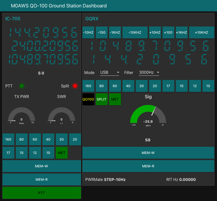
Having the need for full duplex operation on the satellite this complicates things when it comes to VFO tracking and general control of the two radios involved in the solution and so I set about creating a QO-100 Dashboard using the great Node-RED graphical programming environment to create a web app that simplifies the management of the entire setup.

M0AWS QO-100 ground Station Control Dashboard built using Node-RED.

The QO-100 Dashboard synchronises the transmit and receive VFO’s, enables split operation so that you can transmit and receive on different frequencies at the same time and a whole host of other things using very little code. Most of the functionality is created using standard Node-RED nodes. More info on Node-RED can be found on the Opensource.radio Wiki or from the menu’s above.

I’ll be publishing an article all about the QO-100 Dashboard in the very near future along with a downloadable flow file.

I’m extremely pleased with how well the ground station works and have had well in excess of 500 QSO’s on the QO-100 satellite over the last last year.

More soon …
Improving the antennas on Heltec ESP32 v3 Devices

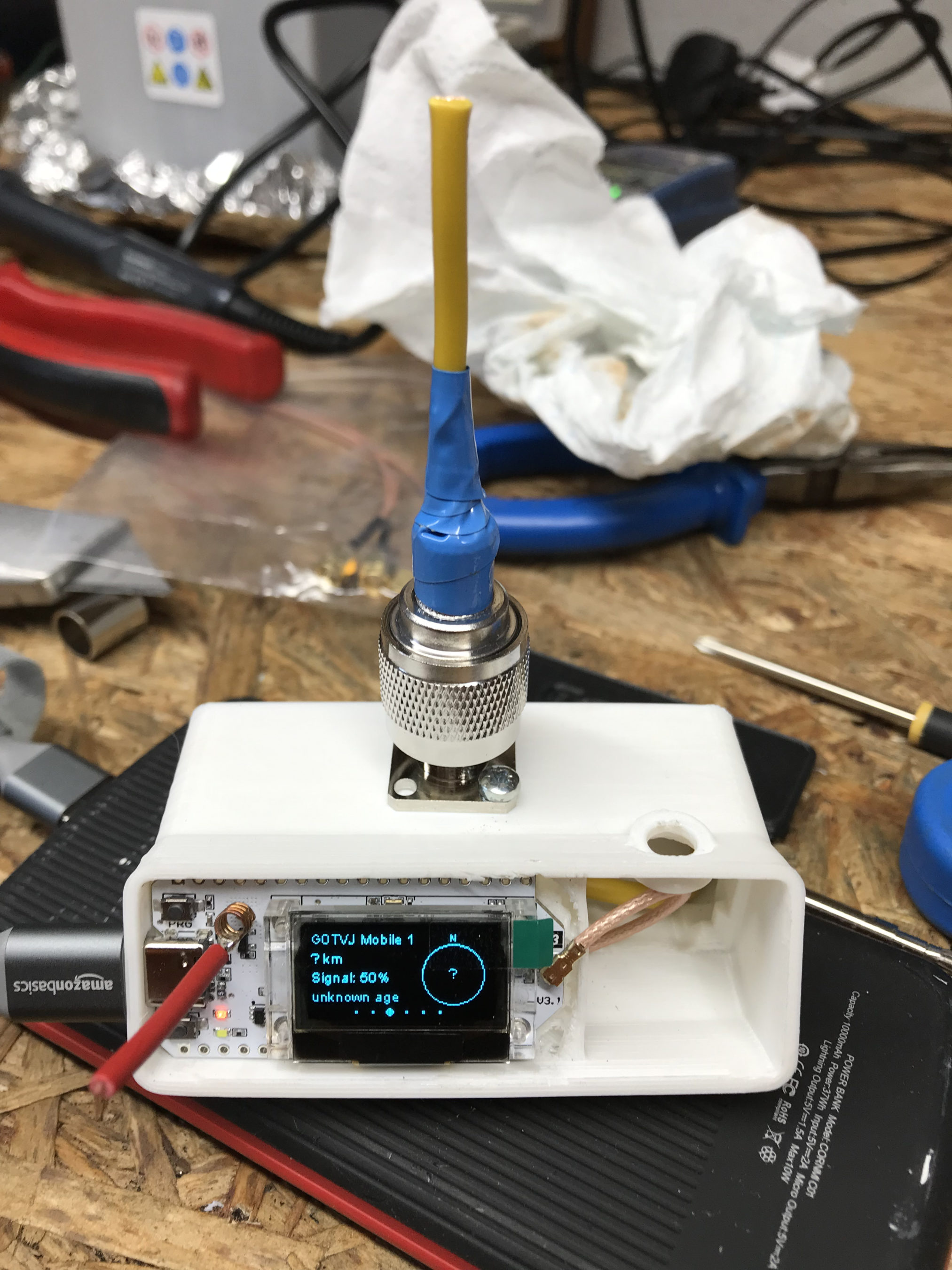
The Heltec ESP32 v3 LORA devices have a coil type Bluetooth/Wifi antenna on the PCB from the factory. This antenna doesn’t work particularly well and has very limited range so, I decided to do something about it.

Getting out the calculator a quarter wave at 2400Mhz is 29.7mm. Looking at the coil antenna on the PCB I decided the best way to connect the new antenna would be to solder it to the coil of the existing antenna. This would short out the coil completely whilst creating a solid mount point for the new antenna.

After a little measuring I decided to use a 31mm long piece of 1.5mm hard core mains cable for the new antenna. I stripped back the insulation from one end of the wire so that the exposed copper wire was exactly the length to short across all the windings of the coil antenna on the PCB.

Attaching replacement Bluetooth Antenna to the Heltec ESP32 v3 Device

Attaching the the wire to the coil was easy enough to do but, it’s worth pointing out that you need to be quick so that the heat doesn’t transfer down onto the PCB desoldering the coil antenna from the device.

Whilst tinkering with the Bluetooth antenna I decided I would also make a neat little quarter wave 868Mhz vertical antenna for this device whilst I had it all apart. This is my Meshtastic node-2 and it’s sole purpose is to allow me to use my iPad to send/receive messages via bluetooth which are then forwarded on to my base node-1 in the house. Node-1 is connected to the house wifi and the Meshtastic MQTT server. This combination allows me to message people on the mesh even though there are no local nodes within RF range.

Running the numbers for the 868Mhz antenna the vertical will need to be around 82.1mm long with a radial of similar length. I had to hand a very nice SMA to N Type chassis mount socket that would be ideal to mount the antenna to the case. I drilled out the holes in the case, measured out the wires and attached it all to the case. Connecting the antenna to the N Type socket I connected my VNA and set about tuning the antenna to resonance.

M0AWS Hidden Radial for the 868Mhz Heltec Antenna

Squeezing the radial and SMA connector into the case I realised I really could do with a 90 degree SMA connector so, I quickly ordered one from Amazon which will be delivered tomorrow. Connecting up my VNA, I had to trim the antenna down to get it to resonance. The SWR ended up at 1.2:1 which is ideal. I ended up cutting off more wire than I thought I would to get the antenna to resonance but, this is due to the extra capacitance caused by the insulation on the wire. If I had used bare copper wire then I wouldn’t of had to cut so much off. I eventually ended up with around 72.9mm of wire for both the antenna and radial.

M0AWS Heltec ESP32 v3 Device with replacement Bluetooth and 868Mhz Antennas

Putting the device back into the case and connecting the USB battery the device fired up and immediately connected to my node in the house. Checking the signal strength of node-1 in the house I could see a 7dB increase in signal strength compared to the little wire antenna that comes with the device. This is a significant improvement for such a simple antenna and well worth the effort.

Next I had to drill a hole in the front of the Heltec case so that the Bluetooth antenna could poke out the front and be bent up vertically. This worked out really well and improved the Bluetooth range massively.

M0AWS Completed alterations to the Heltec ESP32 v3 antennas

Putting the node back in the house and taking my iPad down to the end of the garden some 30m away I could instantly connect to the device via Bluetooth from my iPad, something I’d not been able to do prior to adding the new antennas. I can now use the Heltec device via Bluetooth from anywhere in the house or garden making it much more accessible.

It’s amazing the difference an hour and two little pieces of wire can make to these devices and is well worth the effort.

More soon …
A venture into the world of Meshtastic

Meshtastic is a relatively new thing in the internet of things (IOT) world and is gaining traction in the U.K. at the moment.

So what is Meshtastic?

Meshtastic is an open source, off-grid, decentralised mesh network built to run on affordable, low-power devices on the 868Mhz industrial, scientific, and medical (ISM) band. (Some devices can also run on the 433Mhz 70cm HAM band.)

The ISM band is licence free but, has limits on the RF power levels that can be used. The one plus over the HAM bands is that you can legally transfer encrypted messages over the ISM band making it secure.

The best way to think of Meshtastic is a radio version of the online decentralised Matrix chat system but, without the large server requirements and ever growing database!

Heltec ESP32 v3 Wifi, Bluetooth and 868Mhz device for Meshtastic

There are quite a few Meshtastic compatible devices on the market today with many costing around the £20 mark whilst others like the LillyGo T-Echo costing over £100 in the U.K. even though they are less than half the price in the USA.

Since I’m just starting out on my Meshtastic adventure I thought I’d start with a pair of Heltec ESP32 v3 devices that are normally readily available on Amazon but, due to the current push to build a U.K. wide mesh, they are currently out of stock pretty much everywhere.

Loading the Meshtastic firmware onto the devices is fairly straight forward and can be done using the web installer via either the Edge or Chromium web browsers.
(Note: If using Windows O/S you will need to install some drivers from the Meshtastic website to be able to communicate with the devices)

Having neither of the two browsers and being a Linux command line junkie I decided to use the Python programme to load the firmware onto the two devices. It’s worth noting that you don’t need any drivers to be able to communicate with the devices if you’re using either Debian or one of the many Ubuntu flavours of Linux O/S.

Using the Python command line program sounds like a more complicated approach but, in reality it’s super simple, extremely reliable, quick and if like me you use a Linux PC in the radio shack then you most likely already have most of what you need to get the job done. Just follow the simple steps as laid out on the Meshtastic web site and you’ll have the firmware loaded in no time at all.

Installing the Meshtastic firmware onto my Heltec ESP32 v3 using the Python command line tool

The firmware takes less than a minute to copy across to the Heltec device and is automatically rebooted ready for configuration once the transfer has completed.

It is possible to configure the device via the command line tool however, since there is a nice GUI app for both Apple iOS and Android devices I decided to install the Meshtastic app on my iPad and connect to the device via Bluetooth to configure it.

Once you’ve got the Meshtastic app installed on your device and have connected via Bluetooth you’ll be ready to start configuring the device to join the mesh. The first thing you want to do is set the region. This is different in each country but, in the UK we use the EU_868 region settings. This will set the device to use the 868Mhz ISM band which is the band being used to build the U.K. wide mesh.

View of the Meshtastic app on iOS showing the configuration options for the Heltec ESP32 v3

There is a multitude of configuration options within the app which I will go into in greater detail in a series of articles at a later date.

Heltec ESP32 v3 running Meshtastic Firmware

For those of you that, like me aren’t near any other nodes you can connect the devices to the internet and use the Meshtastic MQTT server to communicate with other nodes. This of course isn’t off-grid but, it will get you started until the mesh grows into your local area at which point your device will automatically start communicating with the other nodes over radio.

Meshtastic MQTT connectivity

Once you are connected to either the MQTT server or other nodes via radio you will see the other node details appear in the Meshtastic app. It’s interesting to look at the information and see signal strengths and traffic levels etc for each node.

View of the Meshtastic app on iOS showing Nodes in the Mesh and Device Metrics for the M0AWS-1 Node

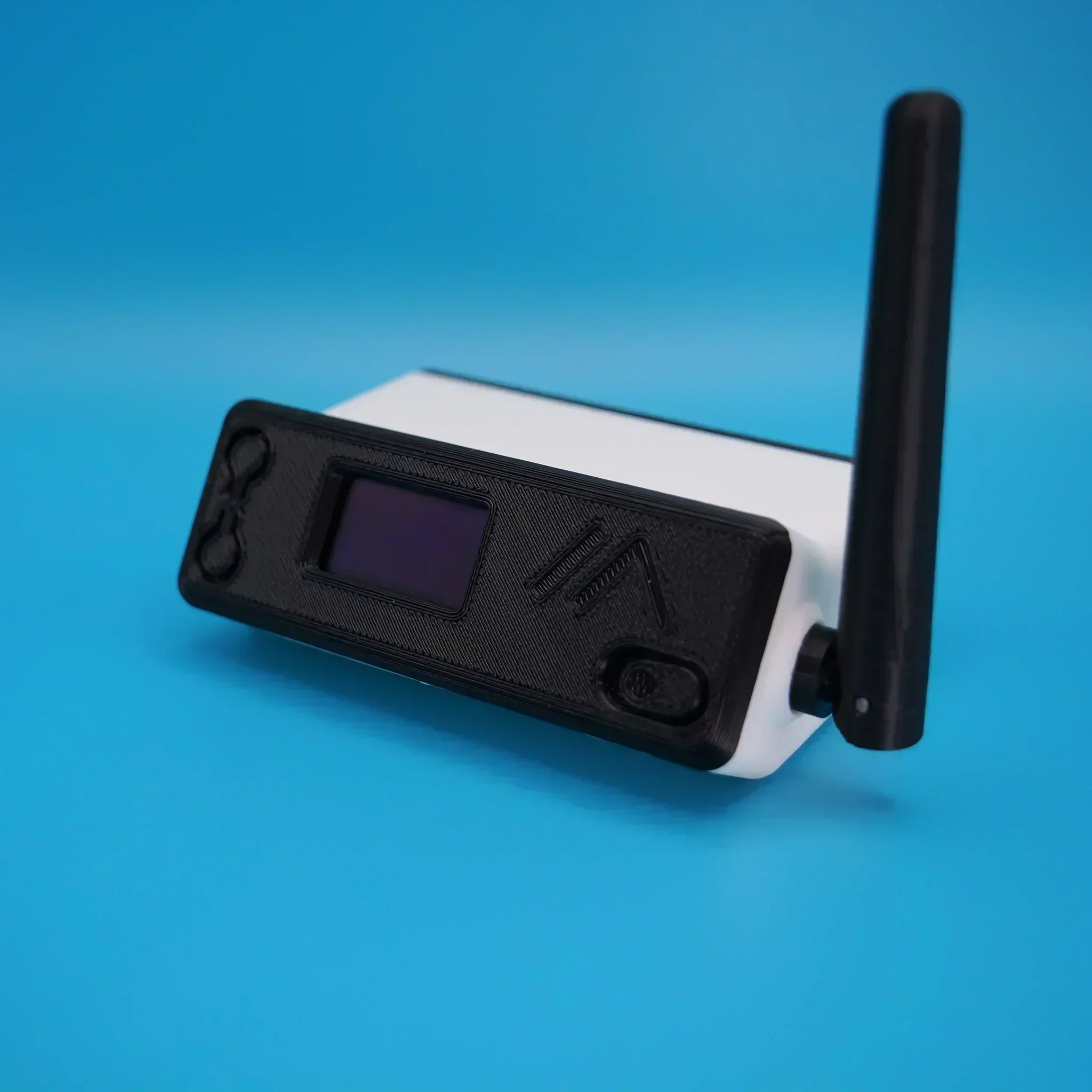
There are a multitude of cases available for the Heltec v3 devices, especially if you have access to a 3D printer. One of the nicest cases I have seen is the Bender from IKB3D (I know, it’s a strange name!) but, it really is a super little case for the Heltec series of devices.

You can either buy the 3D print files for £8.99 and print it yourself or just order a pre-printed and assembled case directly from the website although, due to demand there is a long lead time currently.

More soon …
Replacement for the Funcube Dongle Pro+

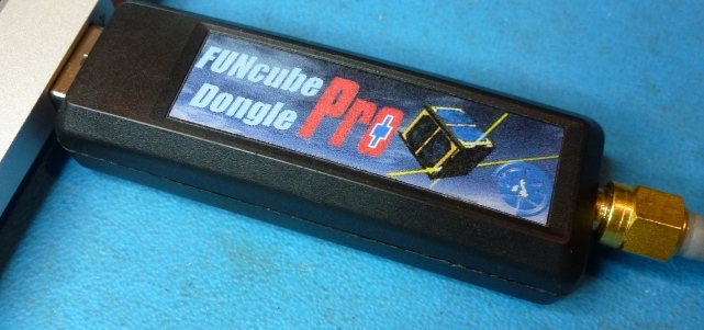
For some time now I’ve been using my Funcube Dongle Pro+ (FCD) as my QO-100 downlink receiver. It’s worked fairly well and has given me the ability to listen to stations on the satellite over the last few months.

During this time I have noticed a couple of things about the FCD that has lead me to the final decision to change to a new SDR device.

The first of these ‘things’ is the fact that the FCD gets seriously overloaded when there are multiple large SSB signals within the receive pass band. The only way to manage this is to constantly keep changing the software based AGC, mix and LNA settings to reduce the levels of the incoming signals so that the overloading stops. This is great except when you tune to a quiet part of the satellite transponder you have to turn all the settings back up again to be able to hear the weaker signals. After a while this becomes tiresome.

The fact that there isn’t a hardware AGC in the FCD is a major drawback when being used for satellite reception especially when it’s on the end of a very high gain LNB and dish antenna.

The second of these ‘things’ is the fact that I can’t see the whole transponder bandwidth at one time with the FCD as it has a very small receive bandwidth capability. This means that I am constantly tuning up and down the transponder to see if there are any stations further up or down in frequency.

Funcube Dongle Pro+
Funcube Dongle Pro+

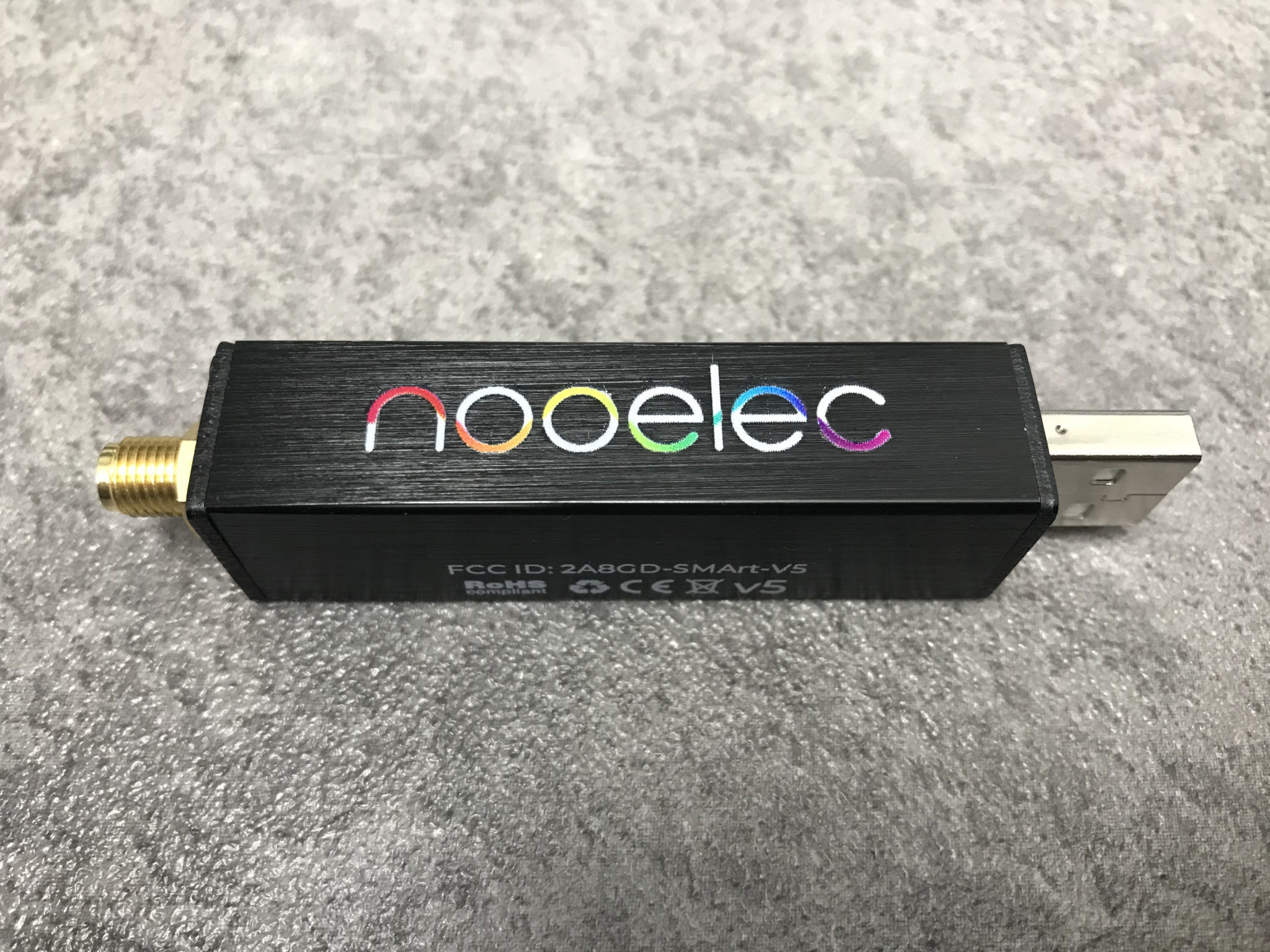
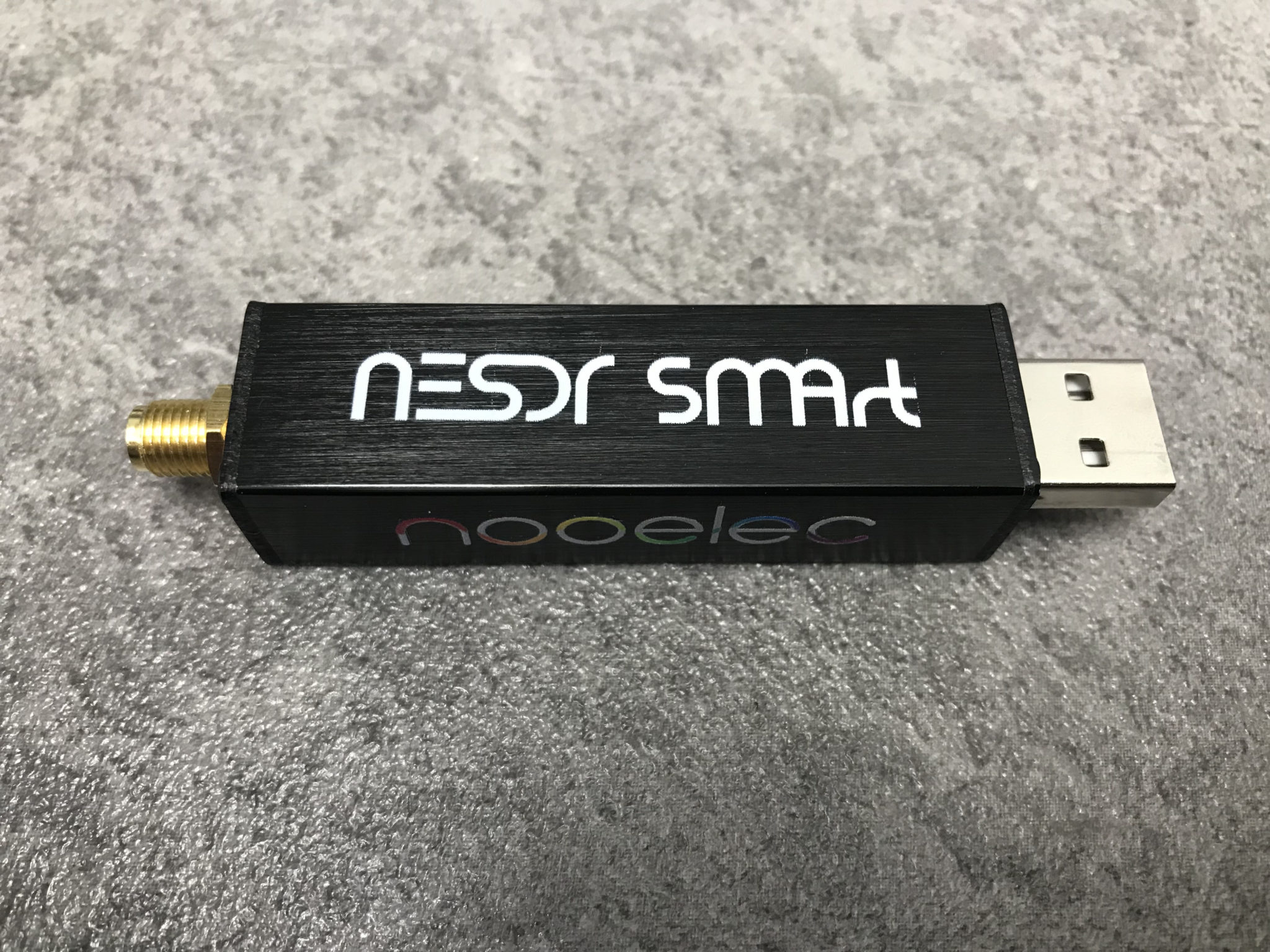
Talking to more experienced satellite operators in the Matrix Amateur Radio Satellites room they recommended replacing the FCD with a NooElec NESDR SMArt v5 that has hardware AGC and is capable of receiving and displaying a much wider bandwidth.

Looking on Amazon the NooElec NESDR SMArt v5 is only £33 so I decided to place an order for one and give it try.

In typical Amazon style the SDR receiver arrived the next day and I wasted no time getting it plugged in and connected to the QO-100 ground station.

The NESDR SMArt v5 is based on the well known RTL-SDR that came onto the market some time back but, has a number of improvements in it that take it to the next level.

The first thing that I was happy with was the fact that the GQRX SDR software I use recognised it immediately on startup, no configuration or drivers were required it just worked, straight out of the box. Since I use Kubuntu Linux on my radio room PC I did wonder if I would need to get into installing extra libraries etc but, thankfully none of that was required.

Looking at the signals from the QO-100 satellite initially they appeared to be nowhere near as strong as they were on with the FCD. Looking at the settings in GQRX I noticed that the hardware AGC was off and the LNA setting was back to it’s default very low level.

I switched on the AGC and then increased the LNA setting to 38.4dB and found that the signals were now plenty strong enough on the display but, not overloading the receiver.

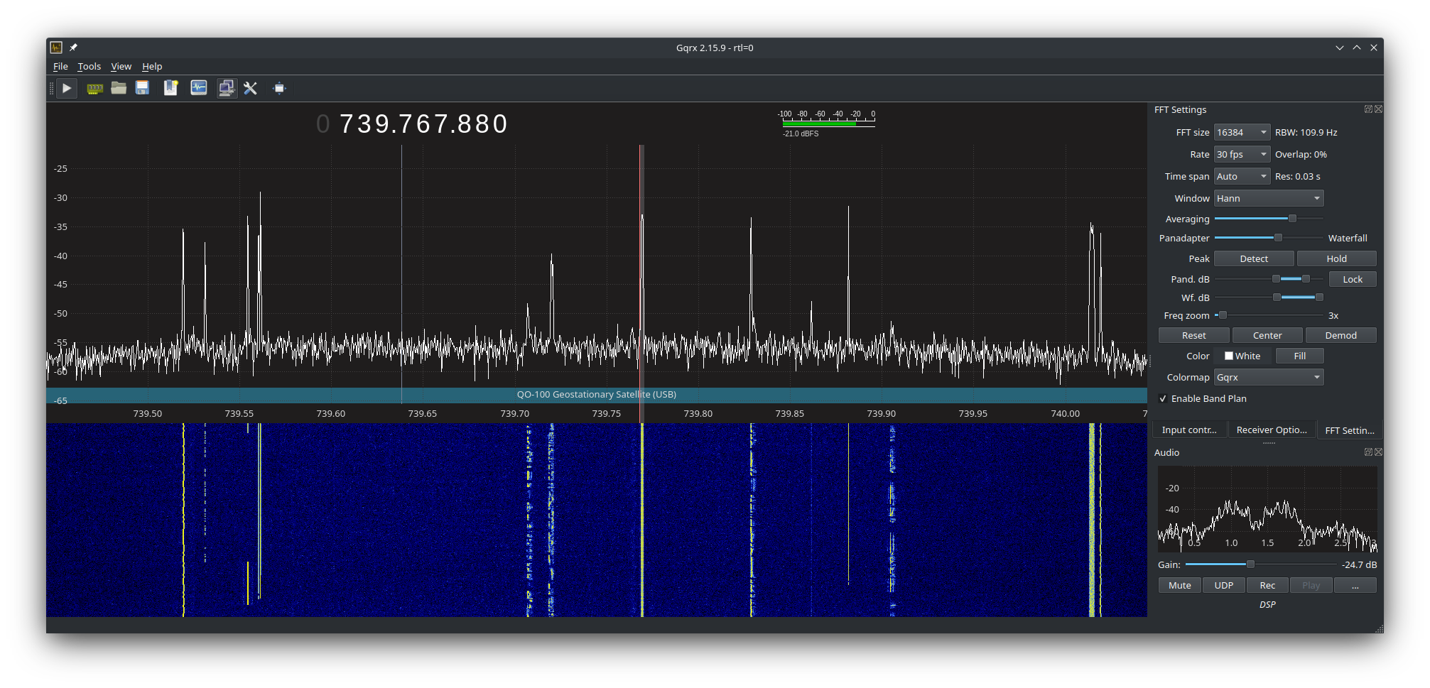
I then went on to adjust the display so that I could see the whole satellite transponder bandwidth on the screen. This is great as it enables me to see the low, middle and high beacons that mark out the narrow band section of the transponder and at a glance see all the stations using the satellite. This was a massive improvement in itself and one that I am very pleased with.

Using the NooElec NESDR SMArt v5 SDR it very soon became clear that it copes with multiple large signals in the pass band so much better than the FCD did. There’s no more overloading of the receiver, no more ghost signals appearing on the waterfall due to the front end not being able to cope and no more having to constantly keep playing with the settings to get things under control. The hardware AGC built into the SDR device does a great job at keeping it all under control whilst receiving a much wider bandwidth than the FCD ever could.

The satellite beacons are now received at S9+15dB without the receiver being overloaded, the first time I have seen this since starting out on my QO-100 venture.

The other thing that became obvious very quickly is that frequency stability is much better than it was with the FCD, it doesn’t drift up and down the transponder now and stays tuned exactly where I put it. It’s also on frequency whereas, the FCD was always 1.7Khz off frequency.

GQRX showing QO-100 Transponder signals

The NooElec NESDR SMArt v5 is very well put together, it has an aluminium case that acts as a heatsink (it does get warm!) and overall the build quality is much better than the plastic cased FCD. When I think that I paid close to £100 for the FCD and the NooElec NESDR SMArt v5 only cost £33, I am amazed at the build quality.

Overall I’m extremely pleased with the purchase of the new SDR, it slotted in perfectly as a replacement for the FCD, works great with GQRX, my QO-100 Node Red Dashboard and performs considerably better than the FCD. Overall money well spent!

You can find the NooElec NESDR SMArt v5 spec sheet here.

More soon …

Use a Griffin Powermate with SDR via Node Red

I’ve been gradually building my QO-100 ground station over the last few months and have had the receive path working for some time now. One of the things I really miss with the Funcube Dongle Pro+ (FCD) SDR is a real VFO knob for changing frequency.

My QO-100 Node Red dashboard is configured so that I can have the FCD track the uplink frequency from the IC-705 but, sometimes I use the FCD without the IC-705 in the shack and so a physical VFO would be handy.

Many years ago when I lived in France (F5VKM) I had a Flexradio Flex-3000 SDR, a great radio in it’s time and one that gave me many hours of enjoyment. One addition I bought for that station was a Griffin Technology Powermate VFO knob. It worked extremely well with the PowerSDR software for the Flex-3000 and I used it for many years.

Many years later I’m back in the UK and much of my equipment is packed away in the attic, including the Griffin Technology Powermate VFO.

I decided to dig it out and see if I could get it working with GQRX SDR software. Sadly I couldn’t get it working with GQRX however, I did find a way of getting it working with Node Red and thus could add it to my QO-100 Node Red Dashboard and then control GQRX with it via a simple Node Red flow.

Griffin Technology Powermate VFO

Plugging the Powermate VFO into my Kubuntu PC it wasn’t immediately recognised by the Linux O/S. After a little searching I found the driver on Github. I added the PPA to my aptitude sources and installed the driver using apt.

https://launchpad.net/~stefansundin/+archive/ubuntu/powermate

Once installed the default config for the Powermate device is to control the default audio device volume. To make the device available for use as a VFO knob you need to change the configuration so that the default setting is disabled. To do this is relatively easy, just edit the config file using your favourite command line editor (Vi/Vim in my case) and add the following entry.

vi /etc/powermate.toml

# Entry to control HDMI volume with Powermate
#sink_name = "alsa_output.pci-0000_01_00.1.hdmi-stereo"

# Set powermate not to work with volume control
sink_name = ""

As shown above, comment out the default “sink_name” entry (Yours may be different depending on audio device in your PC) and add in the Powermate “sink_name” entry that effectively assigns it to nothing.

Once this is done, save the file and exit your editor and then reboot the PC.

Next you’ll need to install a small program called evtest.

sudo apt install evtest

To check the evtest program has installed correctly, plugin your Powermate VFO to any available USB port and run the following command in a terminal.

evtest /dev/input/powermate

Turning the Powermate knob you should see output on the screen showing the input from the device. You should also see BTN events for each press of the Powermate device.

Input driver version is 1.0.1
Input device ID: bus 0x3 vendor 0x77d product 0x410 version 0x400
Input device name: "Griffin PowerMate"
Supported events:
  Event type 0 (EV_SYN)
  Event type 1 (EV_KEY)
    Event code 256 (BTN_0)
  Event type 2 (EV_REL)
    Event code 7 (REL_DIAL)
  Event type 4 (EV_MSC)
    Event code 1 (MSC_PULSELED)
Properties:
Testing ... (interrupt to exit)
Event: time 1685816662.086666, type 2 (EV_REL), code 7 (REL_DIAL), value -1
Event: time 1685816662.086666, -------------- SYN_REPORT ------------
Event: time 1685816662.318638, type 2 (EV_REL), code 7 (REL_DIAL), value -1
Event: time 1685816662.318638, -------------- SYN_REPORT ------------
Event: time 1685816662.574615, type 2 (EV_REL), code 7 (REL_DIAL), value -1
Event: time 1685816662.574615, -------------- SYN_REPORT ------------
Event: time 1685816663.670461, type 2 (EV_REL), code 7 (REL_DIAL), value 1
Event: time 1685816663.670461, -------------- SYN_REPORT ------------
Event: time 1685816664.030421, type 2 (EV_REL), code 7 (REL_DIAL), value 1
Event: time 1685816664.030421, -------------- SYN_REPORT ------------
Event: time 1685816664.334389, type 2 (EV_REL), code 7 (REL_DIAL), value 1
Event: time 1685816664.334389, -------------- SYN_REPORT ------------
Event: time 1685816665.334255, type 1 (EV_KEY), code 256 (BTN_0), value 1
Event: time 1685816665.334255, -------------- SYN_REPORT ------------
Event: time 1685816665.558230, type 1 (EV_KEY), code 256 (BTN_0), value 0
Event: time 1685816665.558230, -------------- SYN_REPORT ------------
Event: time 1685816666.030161, type 1 (EV_KEY), code 256 (BTN_0), value 1
Event: time 1685816666.030161, -------------- SYN_REPORT ------------
Event: time 1685816666.182151, type 1 (EV_KEY), code 256 (BTN_0), value 0
Event: time 1685816666.182151, -------------- SYN_REPORT ------------

At this point you’re ready to stop evtest (CTRL-C) and then create the following little BASH shell script that Node Red will run to collect the O/P from the Powermate USB device.

#!/bin/bash

###############################################
# Griffin Technology Powermate control script #
# for Node Red.                               #
#                                             #
# 04/06/23 - M0AWS - v0.1                     #
#                                             #
###############################################

VAL="1"
echo "STEP-1Hz"

/usr/bin/evtest /dev/input/powermate | while read LINE 
do
   case $LINE in

      *"(REL_DIAL), value 1") echo "$VAL"
           ;;

      *"(REL_DIAL), value -1") echo "-$VAL"
           ;;

      *"(BTN_0), value 1") case $VAL in

                              "1") VAL="10"
                                   echo "STEP-10Hz"
                                      ;;

                             "10") VAL="100"
                                   echo "STEP-100Hz"
                                      ;;

                             "100") VAL="1000"
                                    echo "STEP-1Khz"
                                       ;;

                             "1000") VAL="10000"
                                     echo "STEP-10Khz"
                                         ;;

                             "10000") VAL="1"
                                       echo "STEP-1Hz"
                                          ;;
                              esac
                                 ;;
        esac
done

Once the BASH script is copied and pasted into a file called powermate.sh you need to make it executable by using the following command.

chmod 700 ./powermate.sh

If you now run the shell script in a terminal you’ll see a similar output to that shown below from the device when used.

./powermate.sh 
STEP-1Hz
-1
-1
-1
1
1
1
STEP-10Hz
10
10
10
-10
-10
-10
STEP-100Hz
100
-100
-100
STEP-1Khz
1000
STEP-10Khz
STEP-1Hz
1
1
STEP-10Hz

As you can see above the shell script outputs a positive or negative number for VFO tuning and changes the VFO step size each time the Powermate is depressed.

Getting this output from the BASH shell script into Node Red is really simple to achieve using just 3 or 4 nodes.

In the Node Red development UI create the following nodes.

Griffin Powermate Node Red Nodes

The first node in the flow is a simple inject node, here I called it trigger. This sends a timestamp into the next node in the flow at startup to set the flow running.

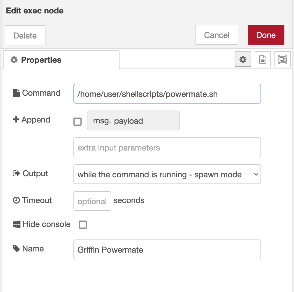
The Griffin Powermate node is a simple exec node that runs the script we created above.

M0AWS Powermate exec node

Configure the node as shown above and connect it to the inject node that’s used as a trigger. Note: Change “user” in the Command field shown above to that of your username on your Linux PC)

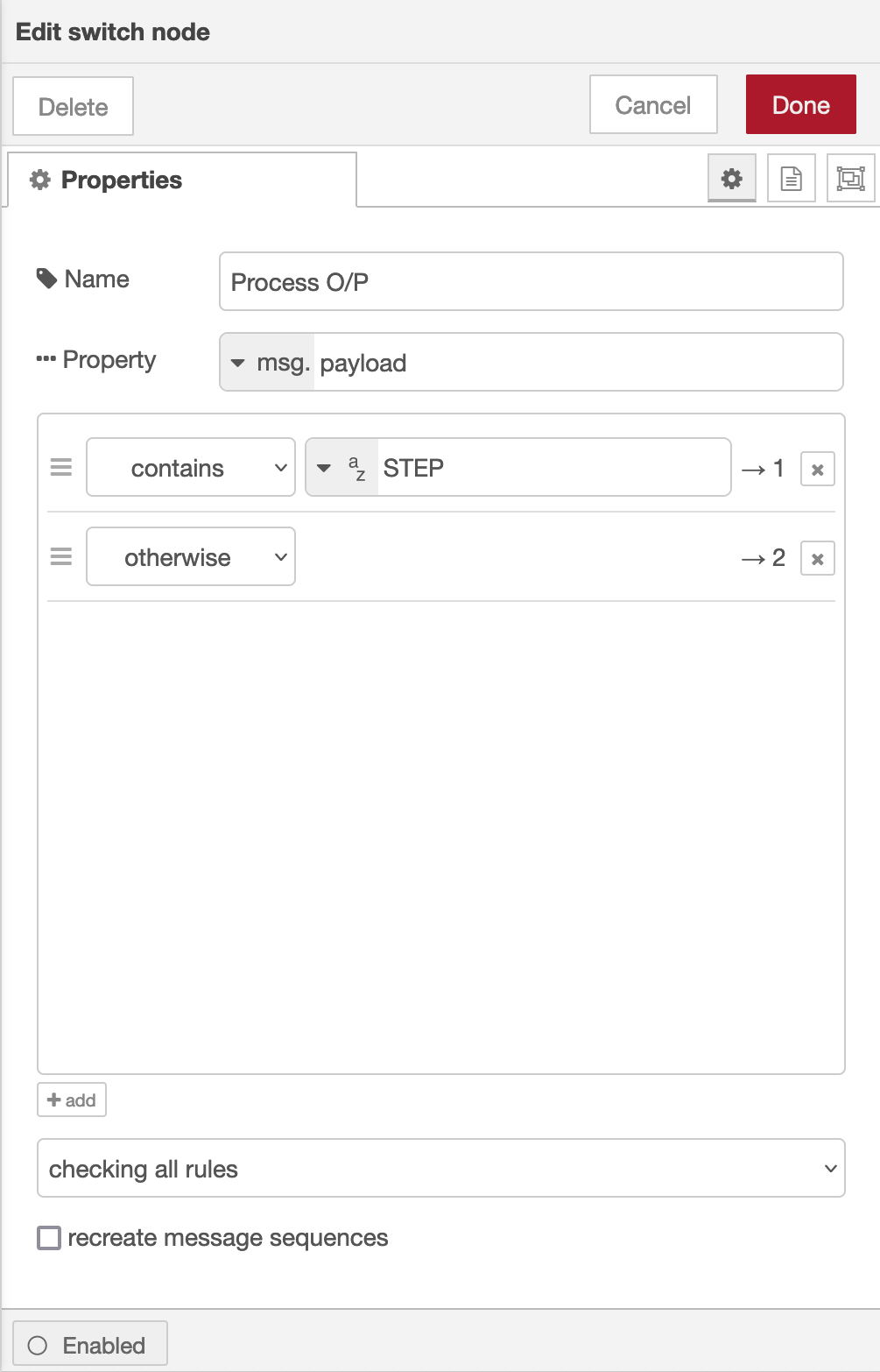
Once done create the third node in the flow, a simple switch node and configure as shown below.

Switch Node for Powermate

The switch node has two outputs, the top one is a text output that is fed into a text field to show the current step size of the Powermate device and the lower output is the numeric output that must be fed into your VFO control flow so that the VFO value is incremented/decremented by the amount output by the Powermate device.

I’ve found the Griffin Technology Powermate USB device works extremely well with Node Red and GQRX that I use for controlling the FCD SDR radio and it’s now part of my QO-100 ground station build.

M0AWS QO-100 Dashboard with Powermate Step Display at bottom

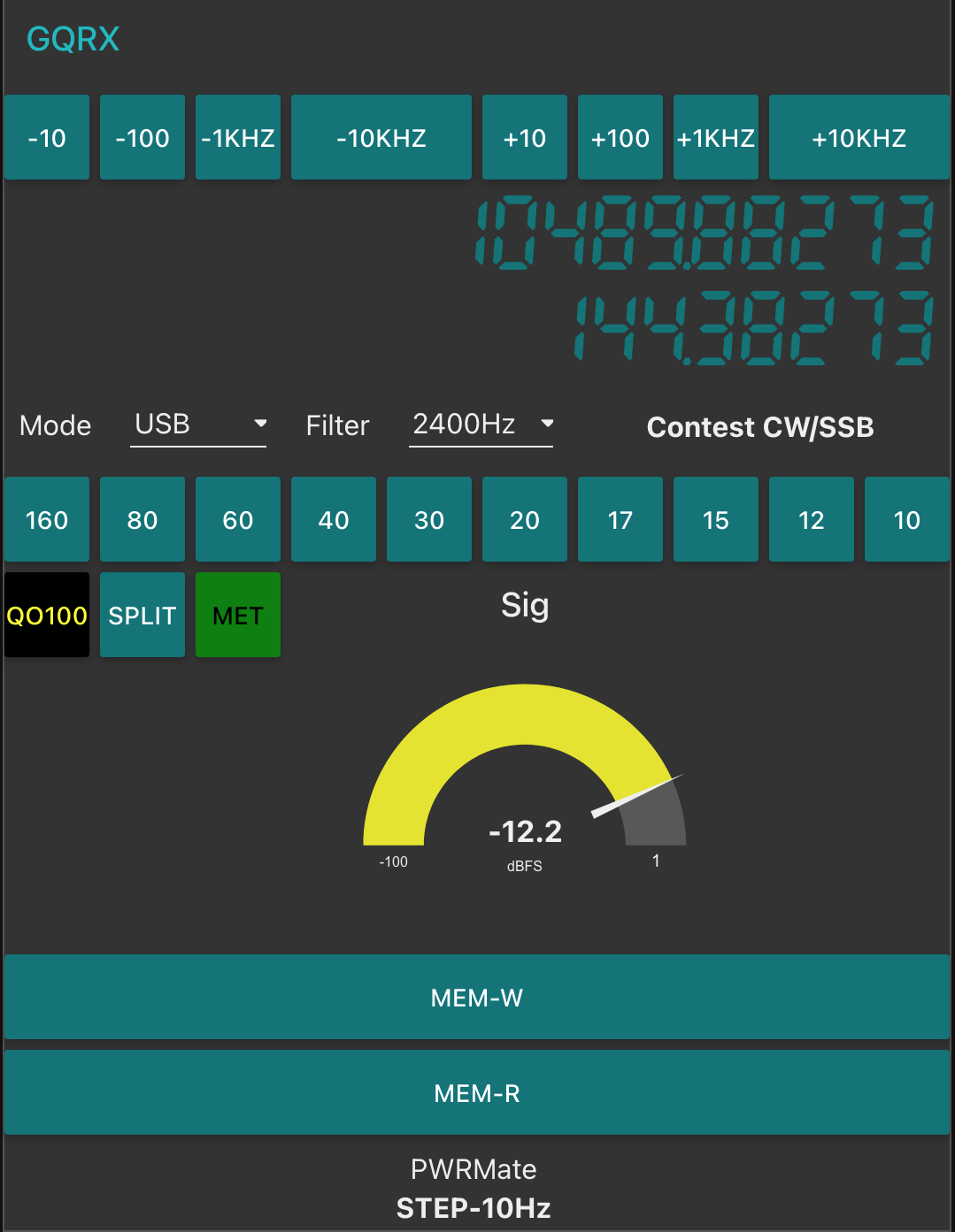
As shown above you can see the Powermate Step size at the bottom of the dashboard, this text changes each time the Powermate device is depressed and will set a step size of 1Hz, 10Hz, 100Hz, 1Khz, 10Khz in a round-robin fashion.

The next stage of the build is the 2.4Ghz transmit path. I now have all the necessary hardware and so this part of the build can finally commence.

More soon …

Social Media – Sucking the life out of our devices

Let me be up front from the outset, this isn’t a HAM Radio related article but, something that probably affects 99% of people today.

I’ve recently given up using social media. Like many of you reading this I had Instagram, Facebook, Twitter etc etc installed and active on all of my devices. Throughout the day and night my iPhone and iPad would be constantly notifying me of posts in the HAM Radio/Motorcycle/Adventure groups I was linked into, or that Jonny/Karen had posted something that I may be interested in, even though 99.99% of the time I wasn’t interested at all.

Even switching off notifications these apps still found ways to continually pester me, so annoying!

Then there was the toxicity, I was genuinely shocked at the constant barrage of hate and anger in the HAM Radio groups. If someone posted something about a radio/antenna/device and others disagreed there was this immediate attack and following argument that went on for days. These nearly always ended up with personal insults and hatred, whatever happened to respecting others opinions?

The HAM Radio groups weren’t the only ones either, the motorcycle groups were just as bad as were the adventure groups, social media really does bring out the worst in people.

Would we all really speak to each other in the same manner face-to-face? I doubt it!

So I deleted all my social media accounts and deleted the apps from all my devices and this is where something very positive happened.

Apart from the fact that my devices were no longer hounding me 24hrs a day, the batteries in my devices were lasting considerably longer.

With the social media apps installed my iPhone battery would barely last a day however, after deleting the apps I was amazed to find that after the next full charge my iPhone battery now lasted 2.5 days without a charge!

Even though I had my iPhone set not to allow the social media apps to update in the background and switched off notifications they were still consuming massive amounts of energy from the battery of the device even when the apps had been closed and were not being used.

Clearly the social media apps are busy skimming data in the background constantly collecting GPS information, movement, app usage etc etc building up a profile for targeted advertising. This data skimming is using considerable amounts of energy from the battery and it has to be questioned if this is reducing the life of device batteries overall.

I found the same on my iPad Pro too, battery life is now considerably longer, not quite as long as my iPhone but, it too is now lasting two days on a single charge even though I use it daily.

So, apart from no longer being exposed to the toxicity of social media, my device batteries are now lasting some 2 to 2.5 times longer allowing me to consume the content that interests me for longer rather than the batteries being discharged by the constant, silent collection of data for social media companies to sell on to advertisers.

If you are an avid social media user then perhaps now is a good time to consider deleting the apps from your devices and instead start using the website interface for each platform, this way you can still get your daily fix of targeted adverts but, without the constant drain on your battery.

Normal content will resume soon …..