A closer look at my Inverted-L Antenna performance

For some time now I’ve been using an Inverted-L style antenna, albeit not a perfect L but, I have found it to perform extremely well.

When I put the antenna up I was aiming for good NVIS radiation on 80/60/40m for chatting Inter-G and local EU stations <1000 miles from my QTH.

I wasn’t expecting good performance on the higher HF bands as the total length of wire is 37m which is somewhat long for the higher frequency bands however, I’ve found performance around Europe to be very good and extremely good over the north pole to Oceania and the USA.
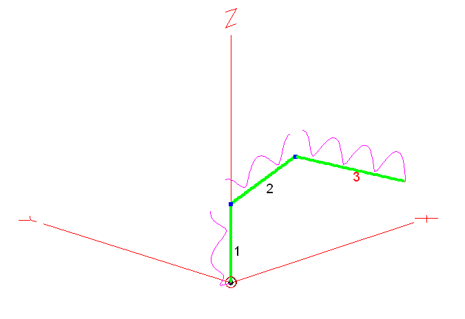
M0AWS Inverted-L style Antenna

As you can see from the antenna view above, it’s not a perfect inverted-L by any means however, its shape has actually proven to be advantageous.

Wire 1 is 9m tall, it then goes approximately 10.5m in length up to a peak of 12m above ground in the centre, this is where I have a 12m Spiderpole for support. From there the remaining 17.5m of wire slopes down to 5m above ground and is attached to the back of the house via a large insulator. Total wire length is 37m.

Wire 1 is at the bottom of a South facing garden and direction +X is north.

The antenna is tuned at the bottom of wire 1 using my CG3000 Remote Auto ATU at ground level. There are a number of random length radials hidden in the lawn and around the perimeter of the garden running mainly from South to North. I cannot run any radials to the south (-X) as this is farmland and not owned by me.

The radio I use is a Hermes Lite 2 SDR paired with a Xiegu XPA125B 100w amplifier. I normally only use 80w or less on all bands and so, my results are achievable using any 100w radio.

On the low bands I find it has great NVIS performance with excellent signal reports from all over the UK and out to around 1500 miles into Europe and beyond. This is exactly what I wanted from the antenna and I’ve been very pleased with it’s performance on 80/60/40m.

Looking at the 2D Far Field Plots on the 3 low bands the antenna has a typical NVIS high angle of radiation pattern with some gain.
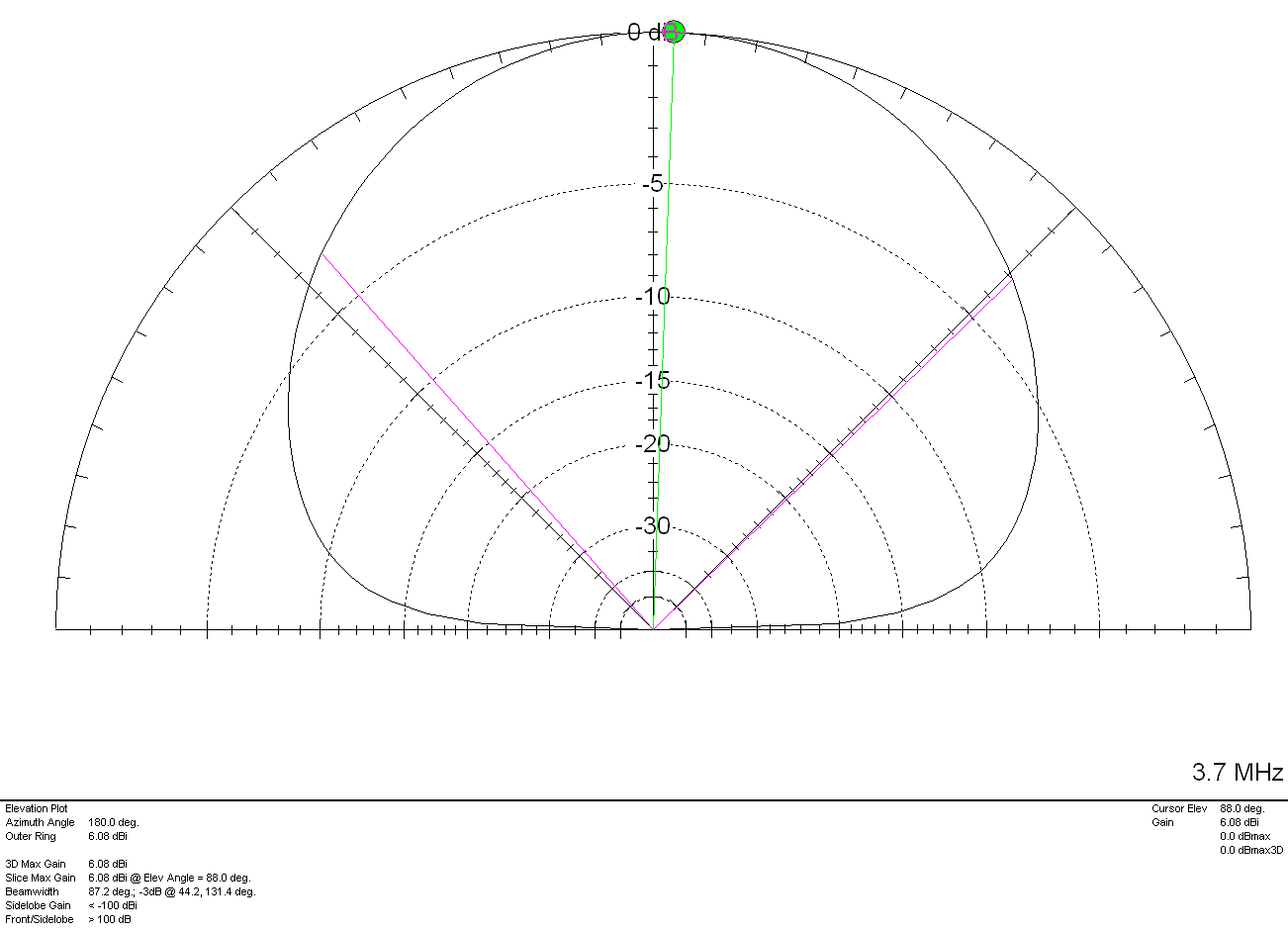
M0AWS Inverted-L Style Antenna 2D Plot on the 80m Band

On the 80m band maximum radiation is straight up, as expected with a gain of 6.08dBi (3.58dBd). The gain reduces at lower angles however, it still performs well out to around 1500 miles and occasionally even further.
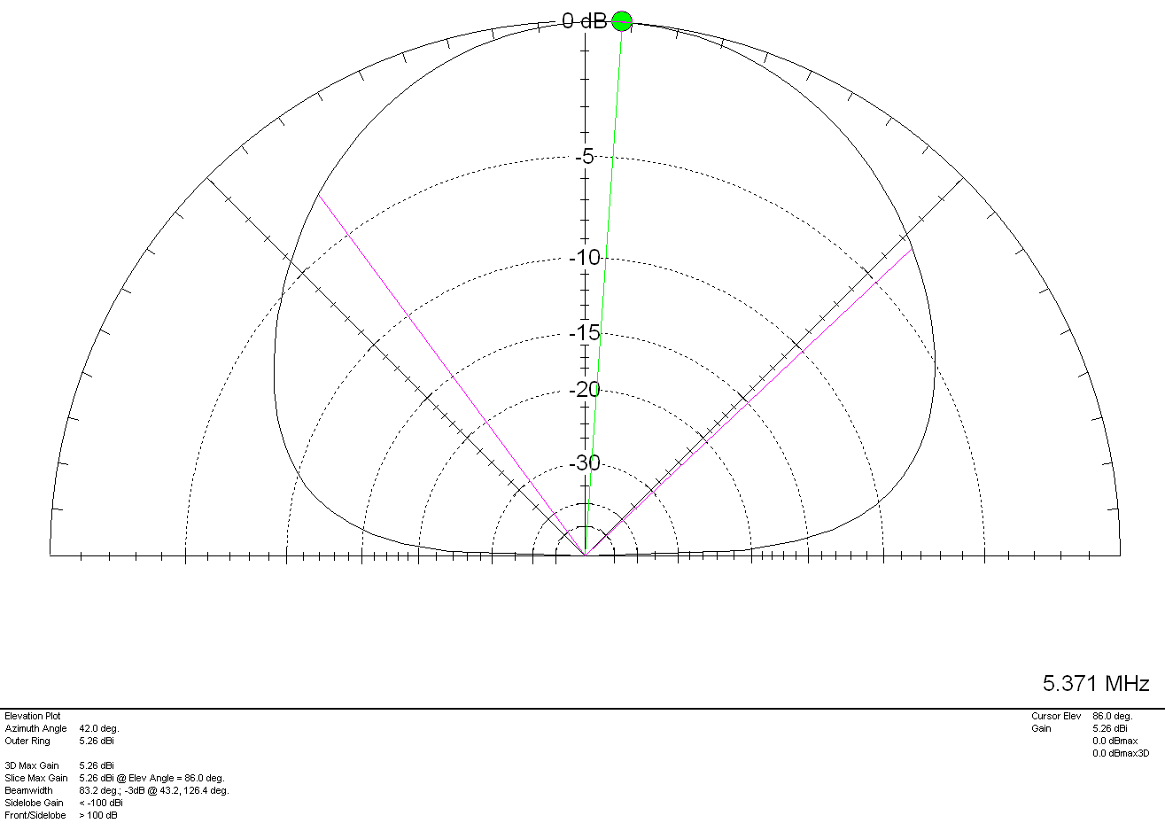
M0AWS Inverted-L Style Antenna 2D Plot on the 60m Band

Once again on the 60m band maximum radiation is pretty much straight up as expected however, I have worked in to Canada many times on 60m with excellent signal reports and so, it also has good DX capability too. With 5.26dBi (2.76dBd) gain it’s not a lossy antenna by any stretch of the imagination.
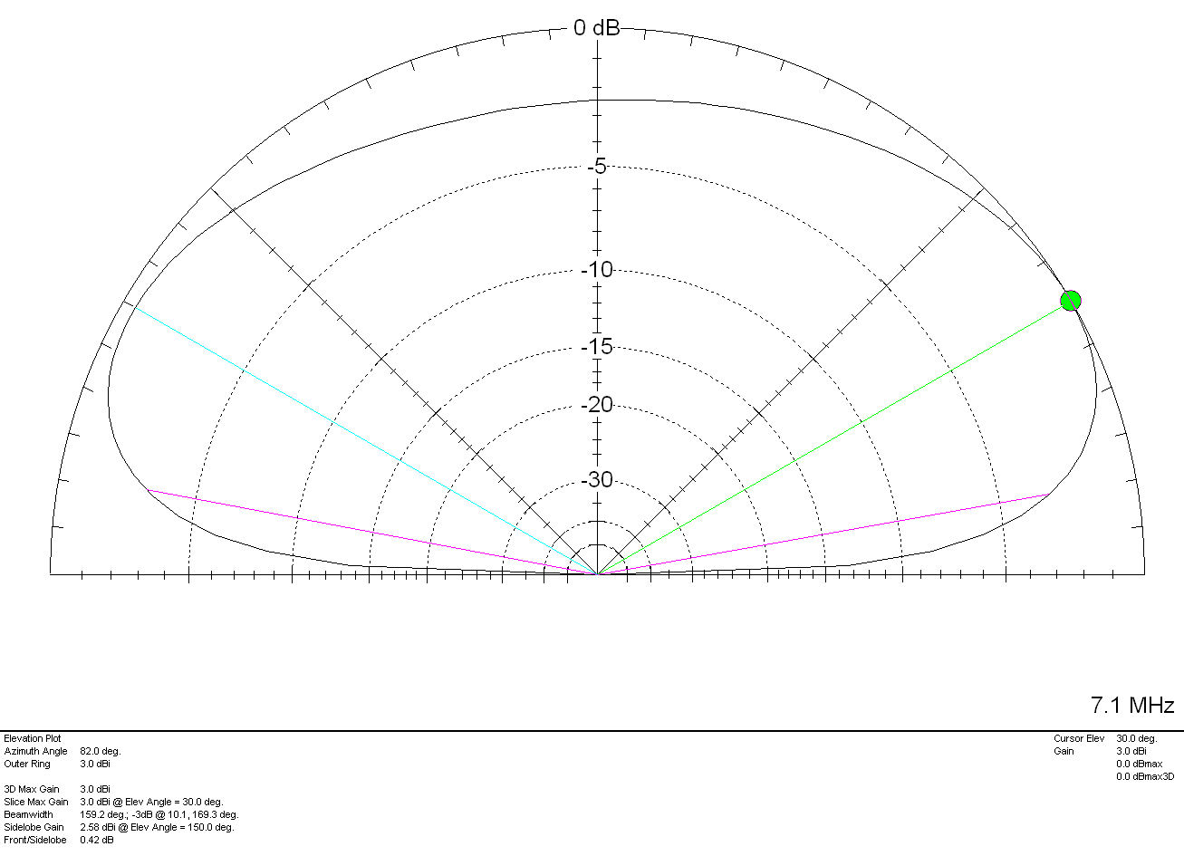
M0AWS Inverted-L Style Antenna 2D Plot on the 40m Band

On the 40m band things start to change a little with the angle of maximum radiation being at 30 degrees rather than straight up. This gives the antenna “longer legs” on the 40m band making it very easy to work longer distances. It’s still very good for Inter-G but, performance over longer distances is considerably better. With a gain of 3.0dBi (0.5dBd) it’s performance is similar to that of a dipole at a similar height above ground.

Above 7Mhz things start to change considerably. The antenna becomes directional to the North West (NW) and North East (NE) giving excellent DX results over the North Pole into North America and Australia/New Zealand. The antenna does of course also have an element of high angle radiation making it useful into Europe and North Africa on the higher bands.
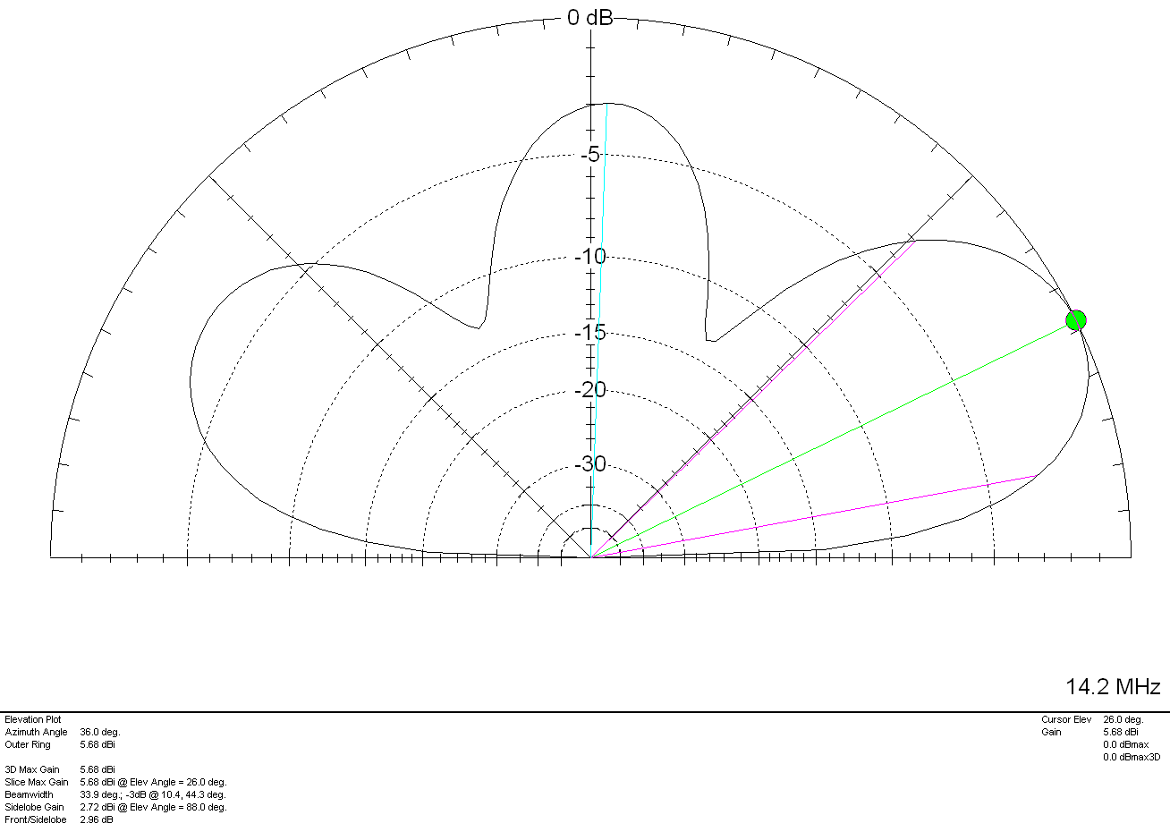
M0AWS Inverted-L Style Antenna 2D Plot on the 20m Band

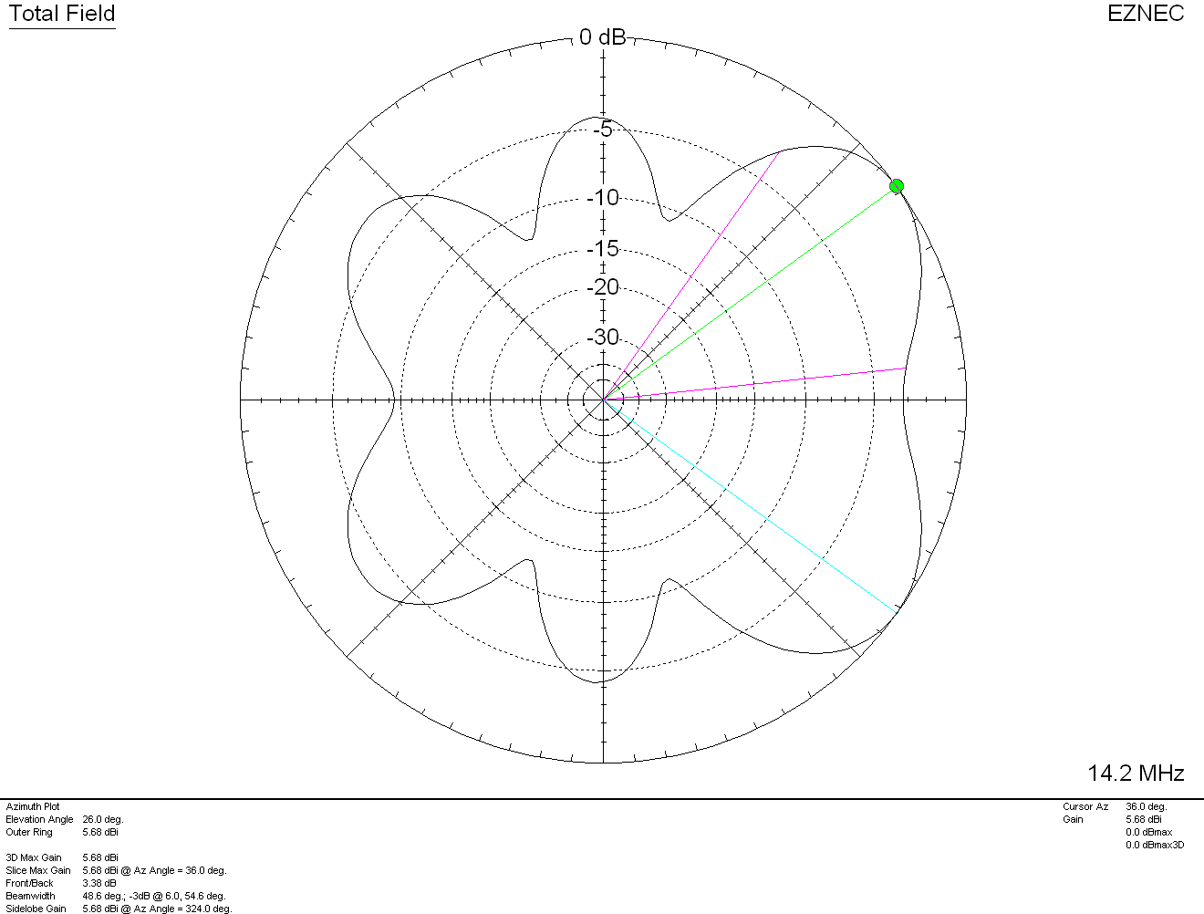
On the 20m band the maximum radiation is at 26 degrees with a gain of 5.68dBi (3.18dBd) pointing NW and NE. There is a lower gain lobe to the South West (SW) and South East (SE) giving excellent coverage through Europe and into Africa as can be seen in the 3D Far Field Plot and Azimuth Slice shown below.
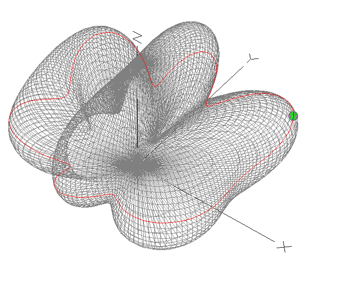
M0AWS Inverted-L Style Antenna 3D Plot on the 20m Band
M0AWS Inverted-L Style Antenna 2D Azimuth Slice on the 20m Band

Moving up in frequency to the 17m band the 3D Plot and Azimuth Slice are similar to that on the 20m band but, with a slightly lower angle of maximum radiation and slightly more gain as can been in the 2D elevation plot shown below.
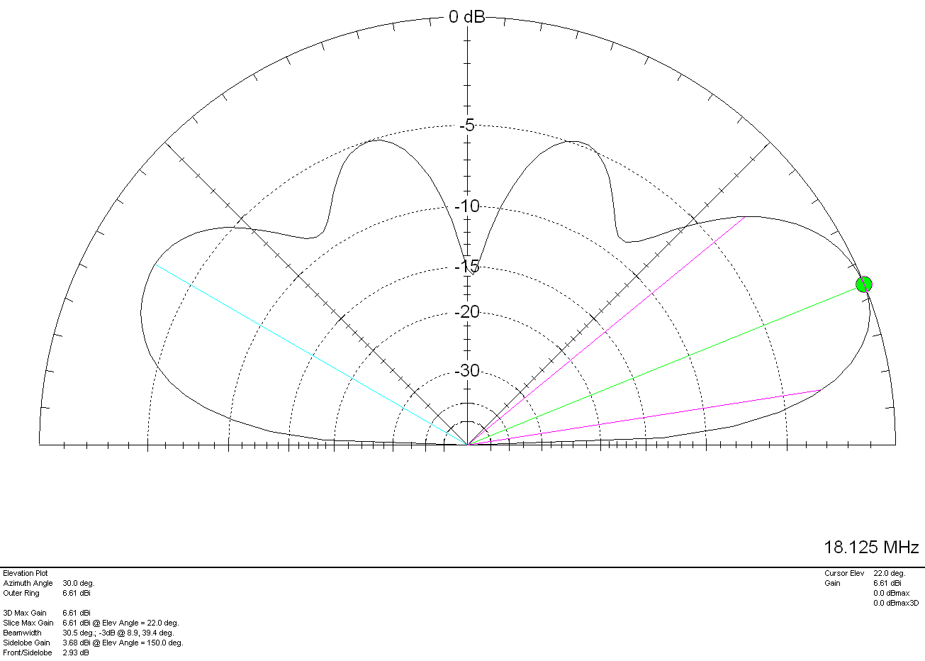
M0AWS Inverted-L Style Antenna 2D Plot on the 17m Band

With a gain of 6.61dbi (4.11dBd) at 22 degrees to the NW and NE and slightly lower gain and higher angle to the SW and SE the antenna has proven to work extremely well on the 17m band. My best DX on 17m so far has been a QSO with Eric, FK8GM in New Caledonia some 10230 miles from my QTH using just 80w of SSB.

The 15m band is a similar story, 7.6dBi (5.1dBd) at just 18 degrees pointing NW and NE. This antenna works extremely well into North America and Oceana (I’ve also worked FK8GM on 15m too). Once again there are lower gain lobes to the SW and SE at a similar angle along with some high angle radiation that aids coverage into Europe. The antenna really is a great all rounder on the 15m band.
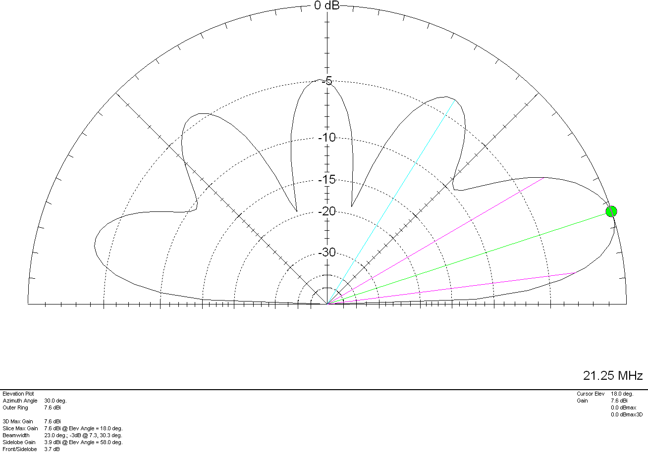
M0AWS Inverted-L Style Antenna 2D Plot on the 15m Band

The 12m and 10m bands are a similar story, low angle, high gain lobes to the NW and NE with lower gain coverage to the SW and SE.
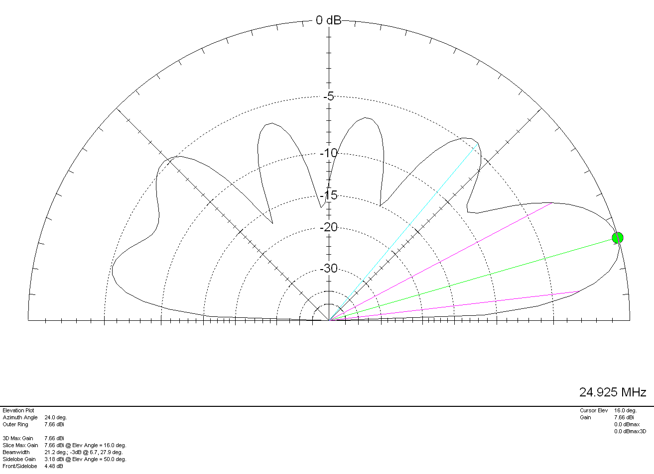
M0AWS Inverted-L Style Antenna 2D Plot on the 12m Band

On 12m the antenna has a very respectable gain of 7.66dBi (5.16dBd) at a low 16 degrees pointing NW and NE making it a great DX antenna. Once again, higher angle lower gain lobes to the SW and SE.

Finally on the 10m band the antenna has a gain of 6.96dBi (4.46dBd) at a very low angle of 14 degrees to the NW and NE. If DXing over the pole on the 10m band is your thing then this simple antenna will certainly help you along and maybe even put a smile on your face.
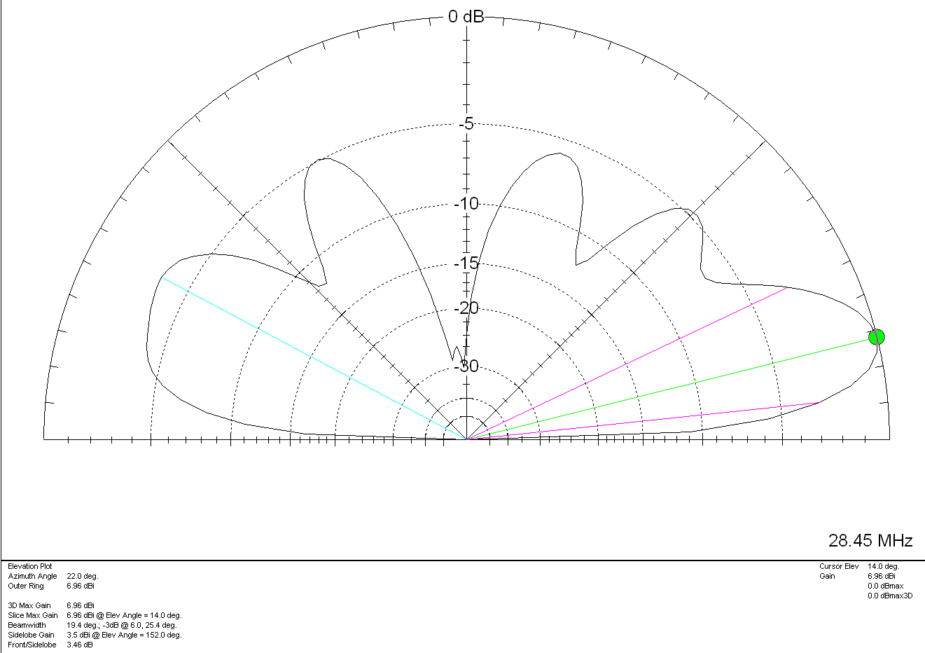
M0AWS Inverted-L Style Antenna 2D Plot on the 10m Band

For such a simple antenna that will fit easily into many typical UK gardens I have been extremely pleased with it’s performance. Whether I’m gassing on the low bands with friends from the Matrix rooms or chasing DX on the higher bands, the antenna has put a smile on my face time and time again.

On receive the antenna is surprisingly quiet, with an S3-4 background noise on the 80/60/40m bands through to less than 1 S point of noise on the higher bands. Picking out the weak DX stations really isn’t a problem.

It just goes to show that you don’t need to spend a fortune on commercial antennas to work the world on the HF bands. With as little as 80w of SSB and a piece of wire connected to a remote ATU you can have just as much fun as the big boys!

More soon …

Using Node-Red to build interactive log maps

I’ve not been on the radio much over the last few weeks as I’ve had my head down other radio related rabbit holes.

One of the rabbit holes is a Node-Red project to make my online logs a little more interactive. For sometime now my logs have been displayed on my website as nicely formatted, searchable HTML pages however, they don’t really allow the viewer (myself included) to see the global coverage of all the contacts so, I decided to write a Node-Red flow that would do just that.

M0AWS Interactive Log Flow

The flow itself isn’t too complicated and basically consists of reading in the individual ADIF formatted log files, processing the data and then sending the data in the correct format to the map node for display.

I’ve had to write a few functions to handle the processing of the ADIF formatted data but, these aren’t particularly complex and are fairly easy to understand even if like me, you’re not a Javascript programmer.

The flow is working perfectly however, I’m in the process of reworking the format generic payload function to reduce the amount of code and make it more efficient.

M0AWS SSB / CW / FreeDV Interactive Log World Map
M0AWS Interactive Log Map Layers Menu


The flow generates two maps, one for voice / CW /Satellite contacts and the other for WSJT-X FT4/8 contacts. Every pin on the map is colour coded by band with satellite contacts being denoted by a satellite icon.

Each pin / icon on the map is clickable and reveals the data of the QSO being displayed.

In the top right-hand corner of the map there is a drop down layer menu that allows the viewer to filter by band thus reducing the number of icons on the screen at any one time.

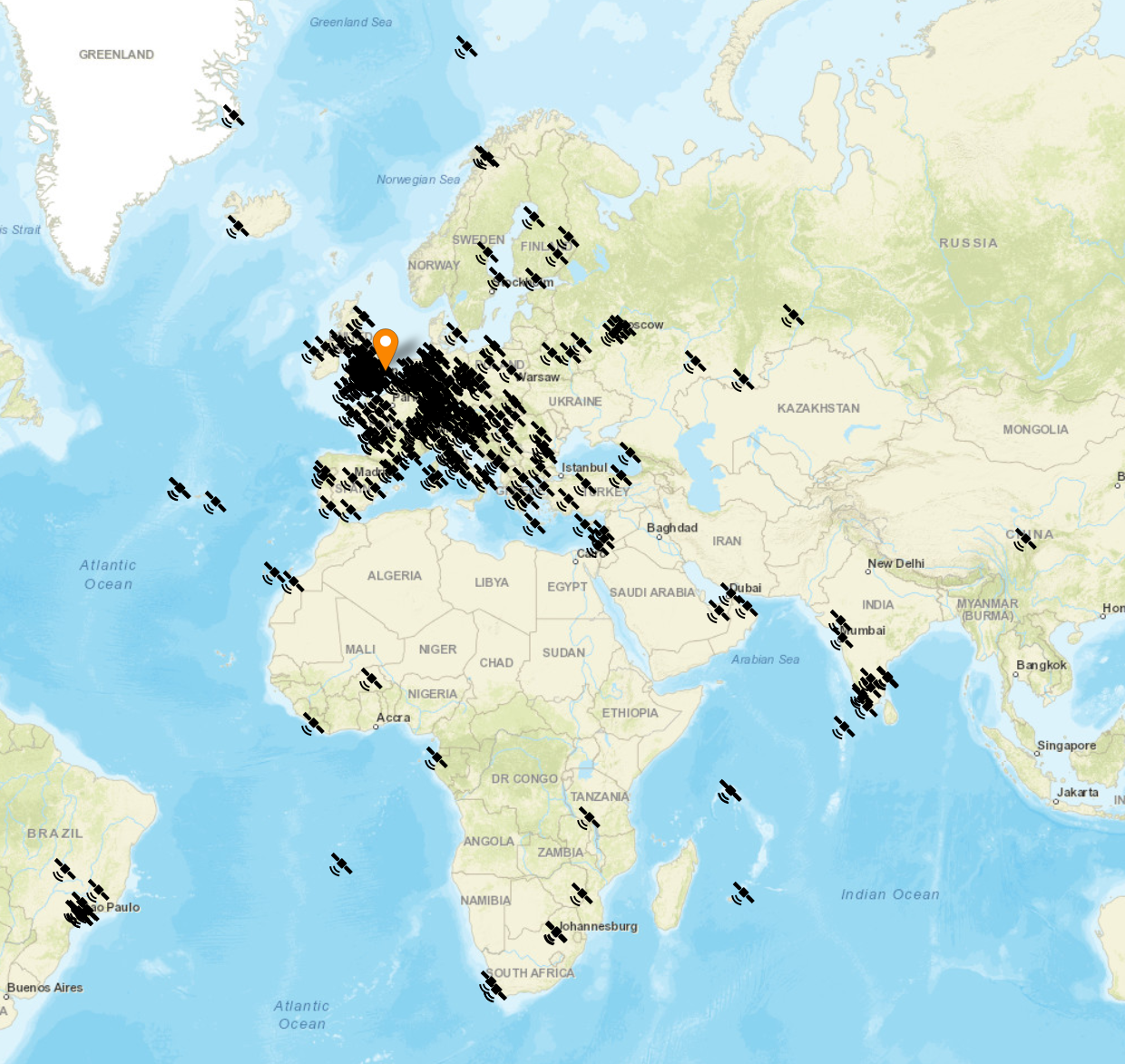
Seeing the data presented on a map really brings my logs alive. An example of this is that I had no idea I’d worked so many stations in India on the QO-100 Satellite.

The small icons in the pins show a microphone for SSB/FM/FreeDV contacts and a downwards pointing triangle in a box for CW contacts. Sadly I couldn’t find a Morse key icon in the collection available.

M0AWS filtered view of QO-100 Satellite contacts

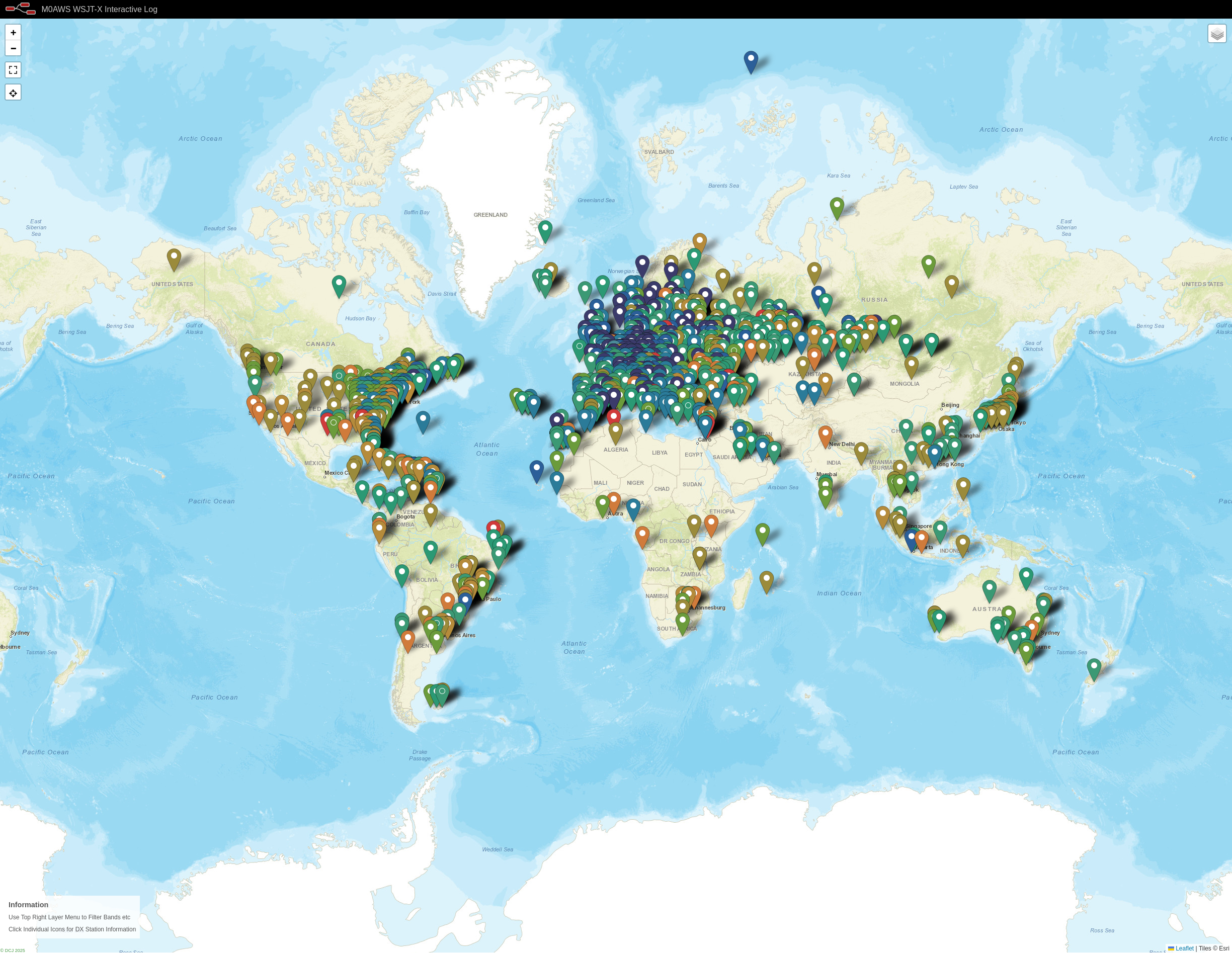
I only use FT4/8 for testing new antenna designs however, it’s interesting to see the global coverage accomplished with this weak signal mode.

M0AWS WSJT-X FT4/8 Interactive Log World Map

Once I’ve finished rewriting the format generic payload function I will make the flow available for download here so that others can also create an interactive view of their radio logs.

If you want to have a look at the maps and try them out for yourself, they are available under the Logs menu above.

This Node-Red instance is running in a virtual machine (VM) on a 16GB RAM RaspberryPi 5 that is also running a number of other VMs at the same time so, it’s safe to say it’s not heavy on CPU and will run on the older Pi4 as well.

More soon …
More 868Mhz Antenna Tests

After initially finding that I couldn’t tune the 868Mhz ground plane antenna with the radials bent down at 45 degrees I decided to experiment to find out why.

Initially I had the radials connected to the 4 corners of the base of the chassis mount N Type socket. This works great if you have the radials completely horizontal and gives an SWR of 1.1:1 but, with the radials bent down at 45 degrees the best SWR is around 2:1.

M0AWS 868Mhz Ground Plane Antenna Close Up

Removing the radials from the base of the N Type chassis socket and soldering them to the outer of the N Type plug at the same level as the feed point for the radiating element I found that an almost perfect SWR can be achieved very easily.

M0AWS 686Mhz Antenna with radials soldered to the N Type Plug
M0AWS 868Mhz Antenna with radials soldered to the N Type Plug

It seemed weird to me that such a small change could have such a big effect on the obtainable SWR for the antenna but, as can be seen in the image below with the radials soldered to the N Type plug and bent downwards I immediately got an SWR of 1.07:1 and a much wider SWR curve.

M0AWS 868Mhz Antenna SWR curve with radials soldered to N Type plug.

By making my own antennas I’m learning a lot about antenna design for the 800-900Mhz frequency range. Minor changes seem to have a much bigger impact than they do at much lower frequencies.

More soon …
868Mhz Ground Plane Vertical Antenna

In my quest to improve my Meshtastic signal range using home-brew antennas I’ve finally put together a neat little ground plane vertical antenna for the 868Mhz ISM band.

The design follows the normal ground plane simplicity using 4 radials and a vertical radiating element albeit on a tiny scale. The radiating element is 82mm long and the radials are each 92mm long.

M0AWS 868Mhz Ground Plane Vertical Antenna

Initially I modelled the antenna at a height of 3m above the ground with the radials tilted downwards at 45 degrees. I took this approach as this is how I have built ground plane verticals for the 70cm band in the past and so I thought I’d try the same approach on the 868Mhz ISM band. (I later found this to be detrimental to tuning!)

The 3D far field plot for the antenna shows it has a very nice, relatively high gain lobe at just 2 degrees elevation with a number of lower gain lobes higher up.

M0AWS 868Mhz Ground Plane Vertical Antenna 3D Far Field Plot

Looking at the 2D far field plot you can get a better understanding of the radiation pattern and gain figures at various angles. At 2 degrees there is 6.7dBi gain with the next major lobe being at 8 degrees with 4.36dBi gain, far more than I imagined I’d see for such a simple antenna.

M0AWS 868Mhz Ground Plane Vertical Antenna 2D Far Field Plot

Putting the antenna together was easy enough with particular attention being paid to the measurements of both the radials and radiating element. I soldered some lugs to the ends of the 2.5mm diameter solid core wire radials to enable easy attachment to the N Type chassis socket that I decided to use as the base for the antenna. This worked out well and provided a good solid mechanical and electrical connection for the 4 radials.

For the radiating element I used an N Type plug with the vertical 2.5mm solid core wire element soldered to the inner centre pin of the male connector. I also slid a small piece of insulation down the wire to stop it from shorting against the metal outer of the plug and then pushed in a tight rubber plug to stop water ingress.

M0AWS 868Mhz Ground Plane Antenna Close Up

Connecting my VNA I found the antenna was mostly resonant at 790Mhz with an SWR of 2.5:1. I knew this would be the case and that the wires would need a little trimming.

Trimming the wires a couple of times in 1mm nibbles I got the point of resonance up to 868Mhz but, the antenna was still exhibiting a lot of reactance that was keeping the SWR above 2:1. Trimming the radials reduced this slightly but, I could not get an SWR much lower than 1.95:1.

Scratching my head I decided to try moving the radials back up so that they were horizontal rather than at 45 degrees downwards, this had the immediate effect of the SWR dropping to 1.1:1.

M0AWS A rather fuzzy photo of the 868Mhz SWR curve for the GP Antenna

The SWR stays below 1.2:1 from 868Mhz to 871Mhz which is plenty wide enough for the Meshtastic devices. Why there is so much reactance when the radials are bent down at 45 degrees I am not sure, but it was easy enough to resolve.

M0AWS 868Mhz Ground Plane Antenna

The finished antenna is tiny but, seems to work well. Signals from my other nodes are up by 6-9dB according to the SNR reports in the Meshtastic app. I now need to make a couple more of these for my other nodes and then hope to hear some other nodes locally once they appear on air.

Remodelling the antenna in EzNEC with the radials as shown above the gain at 2 degrees is now 5.5dBi, down 1.2dBi but, the overall radiation pattern is identical to the original.

Total cost of the build is about £1 and an hour of my time tinkering with it, bargain!

M0AWS-4 Meshtastic Node 868Mhz Antenna Deployment

More soon …

Stray capacitance effects on SWR at 868Mhz

Following on from my last article on improving the Heltec ESP32 v3 antennas I found during the installation of the 90 degree SMA connector that the device was very sensitive to stray capacitance from things around it. After reconnecting my VNA I found the SWR curve would change substantially depending on what the device was near and so I set about rectifying this.

I decided to remove all the insulation from the single radial inside the unit and then added two more radials to increase the ground for the antenna to tune against. I then removed the N type plug with the antenna connected to it and made a new antenna from a piece of 1.5mm solid core insulated mains wire connected directly to the N type socket, without using an N type plug. Tuning to resonance was much easier than before and I soon had the SWR down to 1.2:1. Moving the device around and placing near to other objects the SWR curve was now much more stable than before with only very slight changes in curve shape.

M0AWS Updated 868Mhz Antenna

Making this change to the 868Mhz antenna has shown an improvement in signal strength from my node-1 device of almost +0.5dB, every dB counts when you only have 100mW to play with!

The Bluetooth antenna update has made a massive improvement to the usability of the device via the iOS Meshtastic app. Being able to have a reliable, solid connection from anywhere in the house is great and I no longer lose messages because I’ve strayed outside the range of the Bluetooth connection.

I now have 2 new Heltec ESP32 v3 devices on the way to me and will be getting those configured and operational outside with external antennas in the hope of hearing some nodes locally to me.

More soon …

Improving the antennas on Heltec ESP32 v3 Devices

The Heltec ESP32 v3 LORA devices have a coil type Bluetooth/Wifi antenna on the PCB from the factory. This antenna doesn’t work particularly well and has very limited range so, I decided to do something about it.

Getting out the calculator a quarter wave at 2400Mhz is 29.7mm. Looking at the coil antenna on the PCB I decided the best way to connect the new antenna would be to solder it to the coil of the existing antenna. This would short out the coil completely whilst creating a solid mount point for the new antenna.

After a little measuring I decided to use a 31mm long piece of 1.5mm hard core mains cable for the new antenna. I stripped back the insulation from one end of the wire so that the exposed copper wire was exactly the length to short across all the windings of the coil antenna on the PCB.

Attaching replacement Bluetooth Antenna to the Heltec ESP32 v3 Device

Attaching the the wire to the coil was easy enough to do but, it’s worth pointing out that you need to be quick so that the heat doesn’t transfer down onto the PCB desoldering the coil antenna from the device.

Whilst tinkering with the Bluetooth antenna I decided I would also make a neat little quarter wave 868Mhz vertical antenna for this device whilst I had it all apart. This is my Meshtastic node-2 and it’s sole purpose is to allow me to use my iPad to send/receive messages via bluetooth which are then forwarded on to my base node-1 in the house. Node-1 is connected to the house wifi and the Meshtastic MQTT server. This combination allows me to message people on the mesh even though there are no local nodes within RF range.

Running the numbers for the 868Mhz antenna the vertical will need to be around 82.1mm long with a radial of similar length. I had to hand a very nice SMA to N Type chassis mount socket that would be ideal to mount the antenna to the case. I drilled out the holes in the case, measured out the wires and attached it all to the case. Connecting the antenna to the N Type socket I connected my VNA and set about tuning the antenna to resonance.

M0AWS Hidden Radial for the 868Mhz Heltec Antenna

Squeezing the radial and SMA connector into the case I realised I really could do with a 90 degree SMA connector so, I quickly ordered one from Amazon which will be delivered tomorrow. Connecting up my VNA, I had to trim the antenna down to get it to resonance. The SWR ended up at 1.2:1 which is ideal. I ended up cutting off more wire than I thought I would to get the antenna to resonance but, this is due to the extra capacitance caused by the insulation on the wire. If I had used bare copper wire then I wouldn’t of had to cut so much off. I eventually ended up with around 72.9mm of wire for both the antenna and radial.

M0AWS Heltec ESP32 v3 Device with replacement Bluetooth and 868Mhz Antennas

Putting the device back into the case and connecting the USB battery the device fired up and immediately connected to my node in the house. Checking the signal strength of node-1 in the house I could see a 7dB increase in signal strength compared to the little wire antenna that comes with the device. This is a significant improvement for such a simple antenna and well worth the effort.

Next I had to drill a hole in the front of the Heltec case so that the Bluetooth antenna could poke out the front and be bent up vertically. This worked out really well and improved the Bluetooth range massively.

M0AWS Completed alterations to the Heltec ESP32 v3 antennas

Putting the node back in the house and taking my iPad down to the end of the garden some 30m away I could instantly connect to the device via Bluetooth from my iPad, something I’d not been able to do prior to adding the new antennas. I can now use the Heltec device via Bluetooth from anywhere in the house or garden making it much more accessible.

It’s amazing the difference an hour and two little pieces of wire can make to these devices and is well worth the effort.

More soon …

Getting back onto 160m “Top Band”

Since setting up the new HAM station here in the UK the one band I’ve not yet got back onto is 160m, one of my most favourite bands in the HF spectrum and one that I was addicted to when I live in France (F5VKM).

Having such a small garden here in the UK there is no way I can get any type of guyed vertical for 160m erected and so I needed to come up with some sort of compromise antenna for the band.

Only being interested in the FT4/8 and CW sections of the 160m band I calculated that I could get an inverted-L antenna up that would be reasonably close to resonant. It would require some additional inductance to get the electrical length required and some impedance matching to provide a 50 Ohm impedance to the transceiver.

Measuring the garden I found I could get a 28m horizontal section in place and a 10m vertical section using one of my 10m spiderpoles. This would give me a total of 38m of wire that would get me fairly close to the quarter wave length.

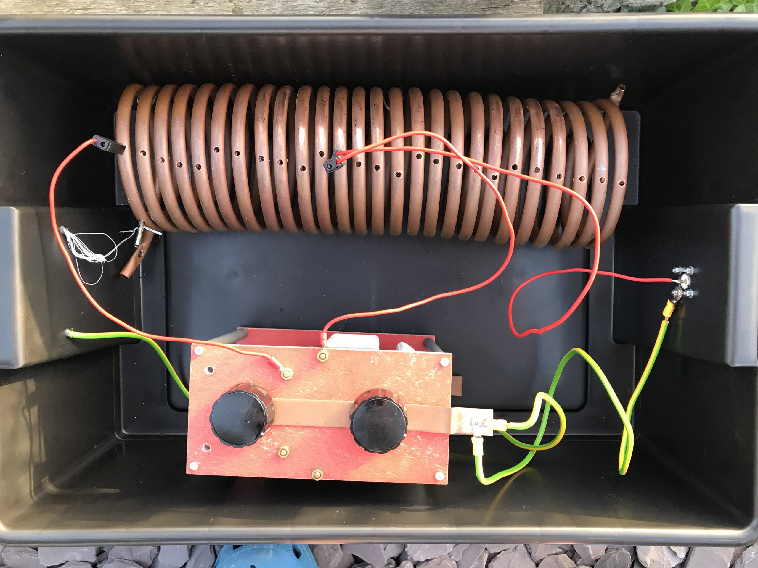
For impedance matching I decided to make a Pi-Network ATU. I’ve made these in the past and found them to be excellent at matching a very wide range of impedances to 50 Ohm.

M0AWS Homebrew Pi-Network ATU

Since I still had the components of the Pi-Network ATU that I built when I lived in France I decided to reuse them as it saved a lot of work. The inductor was made from some copper tubing I had left over after doing all the plumbing in the house in France and so it got repurposed and formed into a very large inductor. The 2 x capacitors I also built many years ago and fortunately I’d kept locked away as they are very expensive to purchase today and a lot of work to make.

Getting the Inverted-L antenna up was easy enough and I soon had it connected to the Pi-Network ATU. I ran a few radials out around the garden to give it something to tune against and wound a 1:1 choke balun at the end of the coax run to stop any common mode currents that may have appeared on the coax braid.

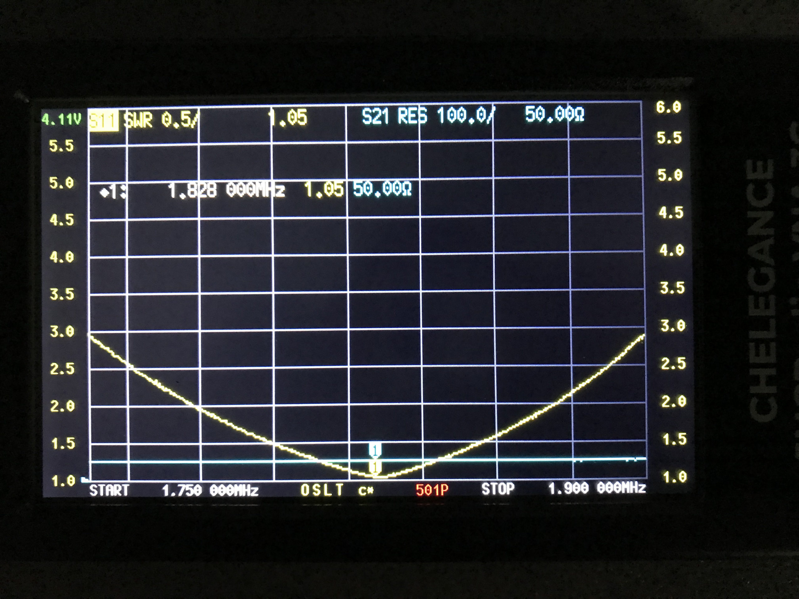
Connecting my JNCRadio VNA I found that the Inverted-L was naturally resonant at 2.53Mhz, not too far off the 1.84Mhz that I needed. Adding a little extra inductance and capacitance via the ATU I soon had the antenna resonant where I wanted it at the bottom of the 160m band.

M0AWS 160m Inverted L Antenna SWR Curve

With the SWR being <1.5:1 across the CW and FT8 section of the band I was ready to get on 160m for the first time in a long.

Since it’s still summer in the UK I wasn’t expecting to find the band in very good shape but, was pleasantly surprised. Switching the radio on before full sunset I was hearing stations all around Europe with ease. In no time at all I was working stations and getting good reports using just 22w of FT8. FT8 is such a good mode for testing new antennas.

As the sky got darker the distance achieved got greater and over time I was able to work into Russia with the longest distance recorded being 2445 Miles, R9LE in Tyumen Asiatic Russia.

In no time at all I’d worked 32 stations taking my total 160m QSOs from 16 to 48. I can’t wait for the long, dark winter nights to see how well this antenna really performs.

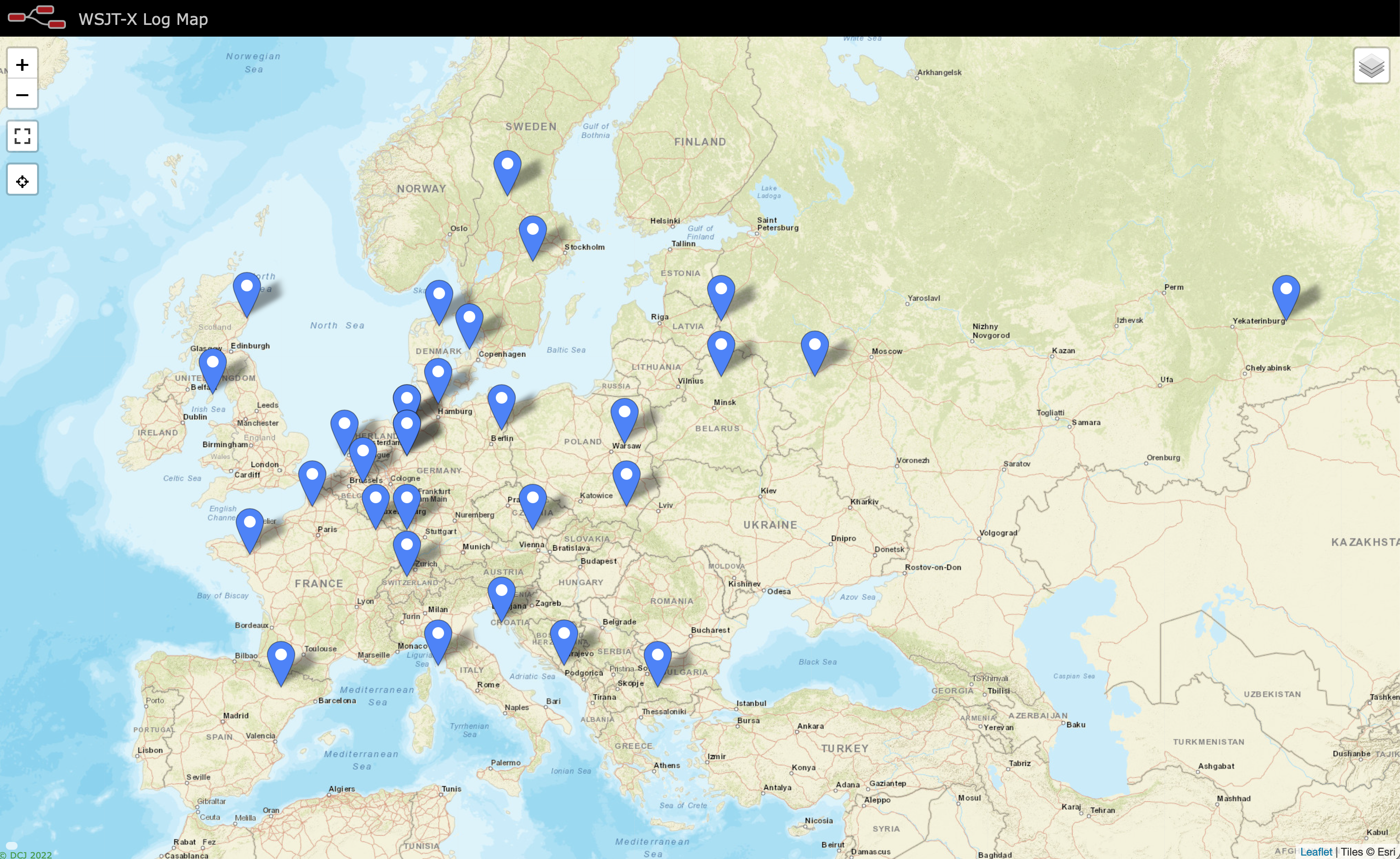
M0AWS Map showing stations worked on 160m using Inverted L Antenna

The map above shows the locations of the stations worked on the first evening using the 160m Inverted-L antenna. As the year moves on and we slowly progress into winter it will be fun to start chasing the DX again on the 160m band..

UPDATE 6th October 2023.
Been using the antenna for some time now with over 100 contacts on 160m. Best 160m DX so far is RV0AR in Sosnovoborsk Asiatic Russia, 3453 Miles using just 22w. Pretty impressive for such a low antenna on Top Band.

More soon …

My First QO-100 Satellite QSO

I’ve been waiting for over a week so far for a male to male SMA connector to arrive from Amazon so that I can connect the 2.4Ghz up-converter to the 2.4Ghz amplifier. Since it still hasn’t arrived I decided to connect the up-converter directly to the IceCone Helix antenna to see if I could get a signal into the QO-100 satellite.

To my surprise I could easily hear my CW signal on QO-100 even though the total output from the up-converter is only 200mW.

I didn’t expect to be able to hear my signal since it’s a tiny amount of power that has to travel some 22500 miles to the satellite but, I could hear it and was amazed that it was peaking S8 on my SDR receiver.

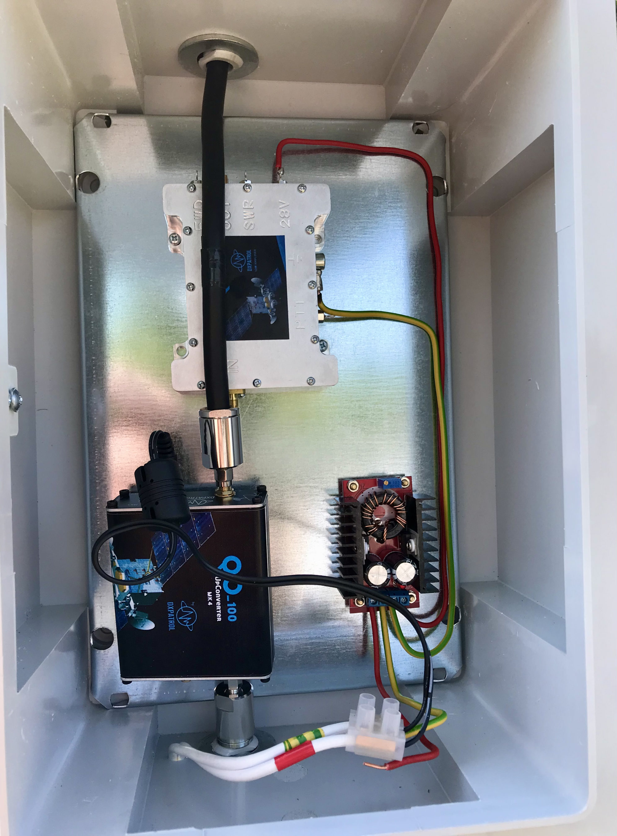
2.4Ghz Up-COnverter connected directly to the antenna bypassing the 2.4Ghz Amplifier
2.4Ghz Up-Converter connected directly to the antenna bypassing the 2.4Ghz Amplifier

Being excited I put out a CQ call that was soon answered by OH5LK, Jussi in Finland. Jussi gave me a 579 report which I was extremely pleased with. He was of course much stronger at a 599+ at my end. We had a quick QSO and exchanged details without any problems at all. Its really nice to get a QRPp contact without any QSB or QRM.

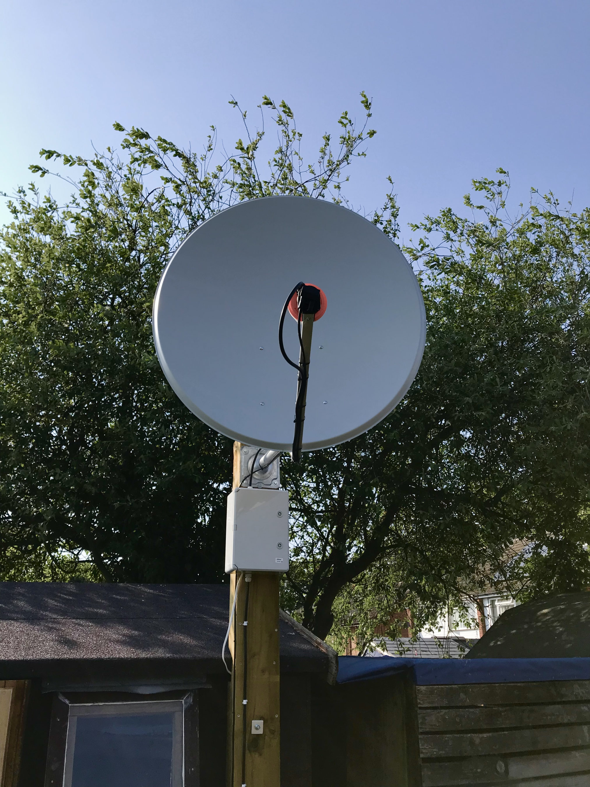
M0AWS QO-100 1.1m off-set Dish and IceCone Helix antenna ground station

Neil, G7UFO who I chat with regularly in the Matrix Amateur Radio Satellites room has posted a connector out to me so I’m hoping it will arrive on Monday and then I’ll be able to connect the amplifier and hopefully get a few SSB contacts.

UPDATE: I’ve since had 2 SSB contacts via QO-100 using just the 200mW O/P from the up-converter. Both times I got a 3/3 report not brilliant but, perfectly acceptable for the amount of power I’m putting out.

More soon …

Replacement for the Funcube Dongle Pro+

For some time now I’ve been using my Funcube Dongle Pro+ (FCD) as my QO-100 downlink receiver. It’s worked fairly well and has given me the ability to listen to stations on the satellite over the last few months.

During this time I have noticed a couple of things about the FCD that has lead me to the final decision to change to a new SDR device.

The first of these ‘things’ is the fact that the FCD gets seriously overloaded when there are multiple large SSB signals within the receive pass band. The only way to manage this is to constantly keep changing the software based AGC, mix and LNA settings to reduce the levels of the incoming signals so that the overloading stops. This is great except when you tune to a quiet part of the satellite transponder you have to turn all the settings back up again to be able to hear the weaker signals. After a while this becomes tiresome.

The fact that there isn’t a hardware AGC in the FCD is a major drawback when being used for satellite reception especially when it’s on the end of a very high gain LNB and dish antenna.

The second of these ‘things’ is the fact that I can’t see the whole transponder bandwidth at one time with the FCD as it has a very small receive bandwidth capability. This means that I am constantly tuning up and down the transponder to see if there are any stations further up or down in frequency.

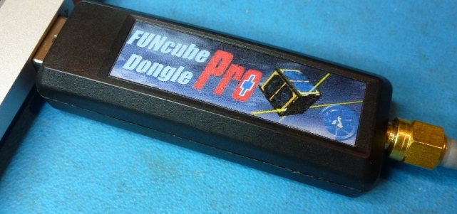
Funcube Dongle Pro+
Funcube Dongle Pro+

Talking to more experienced satellite operators in the Matrix Amateur Radio Satellites room they recommended replacing the FCD with a NooElec NESDR SMArt v5 that has hardware AGC and is capable of receiving and displaying a much wider bandwidth.

Looking on Amazon the NooElec NESDR SMArt v5 is only £33 so I decided to place an order for one and give it try.

In typical Amazon style the SDR receiver arrived the next day and I wasted no time getting it plugged in and connected to the QO-100 ground station.

The NESDR SMArt v5 is based on the well known RTL-SDR that came onto the market some time back but, has a number of improvements in it that take it to the next level.

The first thing that I was happy with was the fact that the GQRX SDR software I use recognised it immediately on startup, no configuration or drivers were required it just worked, straight out of the box. Since I use Kubuntu Linux on my radio room PC I did wonder if I would need to get into installing extra libraries etc but, thankfully none of that was required.

Looking at the signals from the QO-100 satellite initially they appeared to be nowhere near as strong as they were on with the FCD. Looking at the settings in GQRX I noticed that the hardware AGC was off and the LNA setting was back to it’s default very low level.

I switched on the AGC and then increased the LNA setting to 38.4dB and found that the signals were now plenty strong enough on the display but, not overloading the receiver.

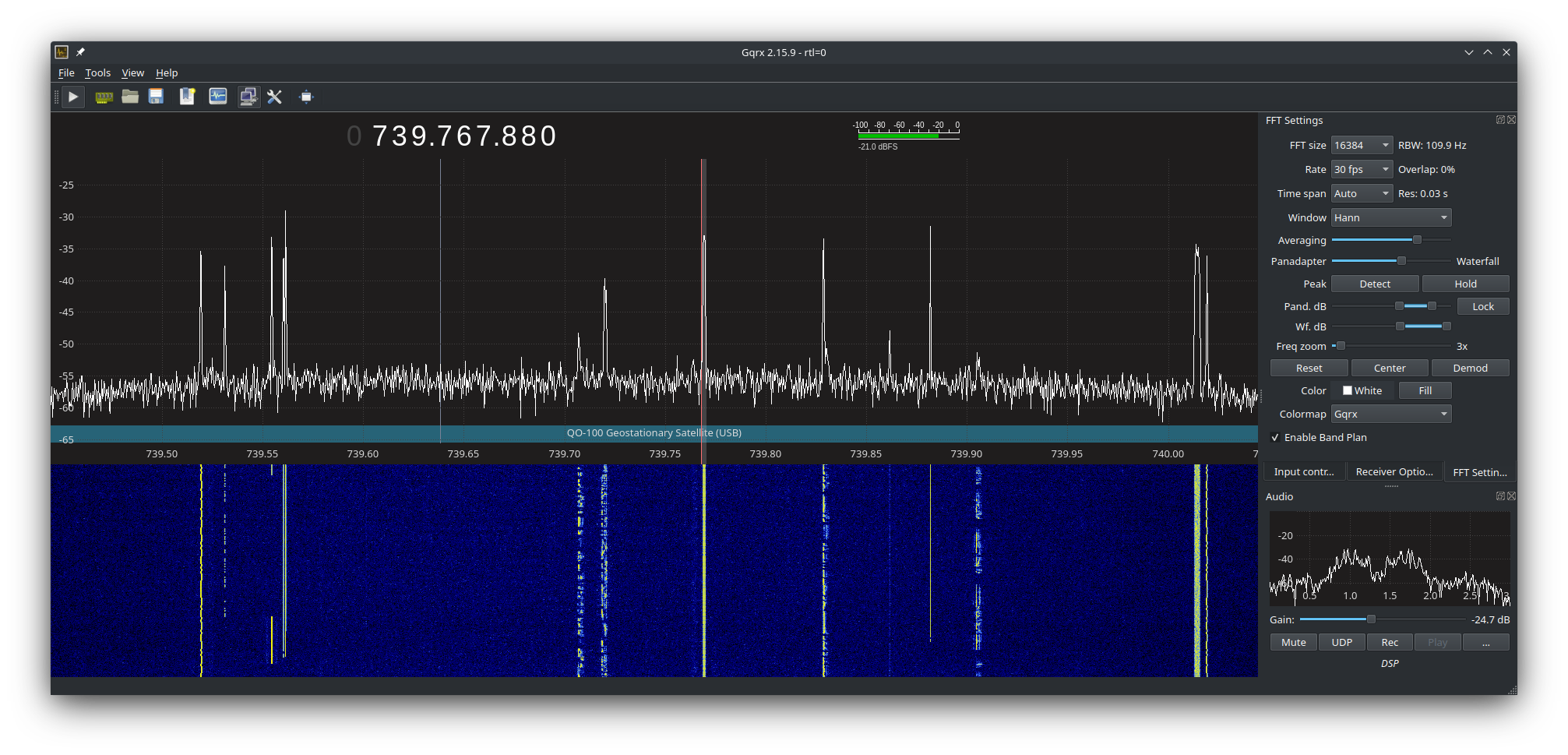
I then went on to adjust the display so that I could see the whole satellite transponder bandwidth on the screen. This is great as it enables me to see the low, middle and high beacons that mark out the narrow band section of the transponder and at a glance see all the stations using the satellite. This was a massive improvement in itself and one that I am very pleased with.

Using the NooElec NESDR SMArt v5 SDR it very soon became clear that it copes with multiple large signals in the pass band so much better than the FCD did. There’s no more overloading of the receiver, no more ghost signals appearing on the waterfall due to the front end not being able to cope and no more having to constantly keep playing with the settings to get things under control. The hardware AGC built into the SDR device does a great job at keeping it all under control whilst receiving a much wider bandwidth than the FCD ever could.

The satellite beacons are now received at S9+15dB without the receiver being overloaded, the first time I have seen this since starting out on my QO-100 venture.

The other thing that became obvious very quickly is that frequency stability is much better than it was with the FCD, it doesn’t drift up and down the transponder now and stays tuned exactly where I put it. It’s also on frequency whereas, the FCD was always 1.7Khz off frequency.

GQRX showing QO-100 Transponder signals

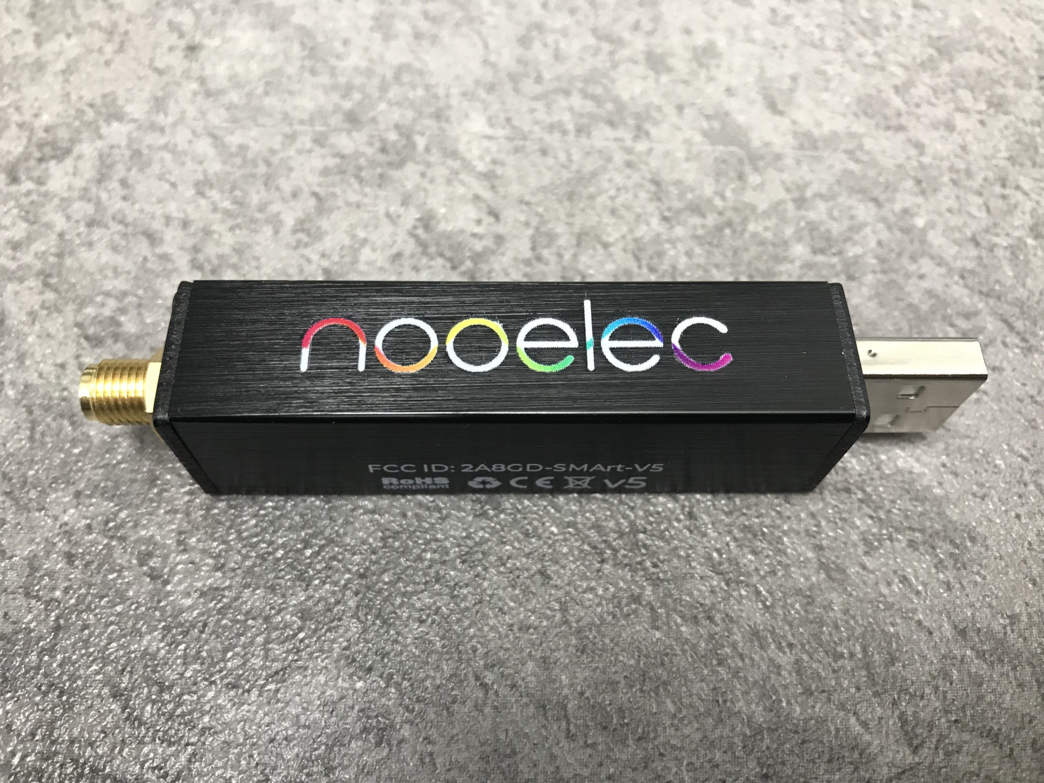
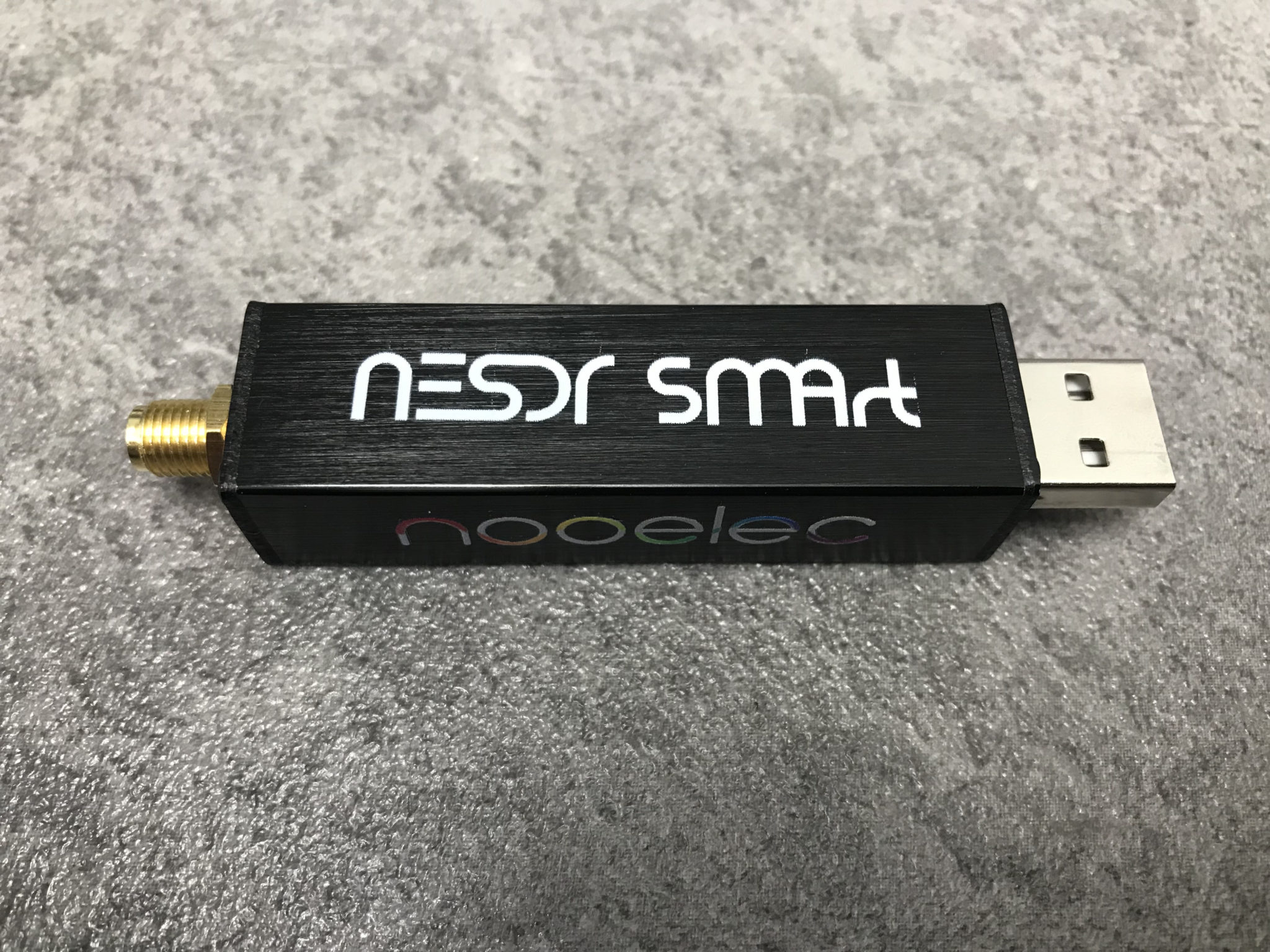
The NooElec NESDR SMArt v5 is very well put together, it has an aluminium case that acts as a heatsink (it does get warm!) and overall the build quality is much better than the plastic cased FCD. When I think that I paid close to £100 for the FCD and the NooElec NESDR SMArt v5 only cost £33, I am amazed at the build quality.

Overall I’m extremely pleased with the purchase of the new SDR, it slotted in perfectly as a replacement for the FCD, works great with GQRX, my QO-100 Node Red Dashboard and performs considerably better than the FCD. Overall money well spent!

You can find the NooElec NESDR SMArt v5 spec sheet here.

More soon …

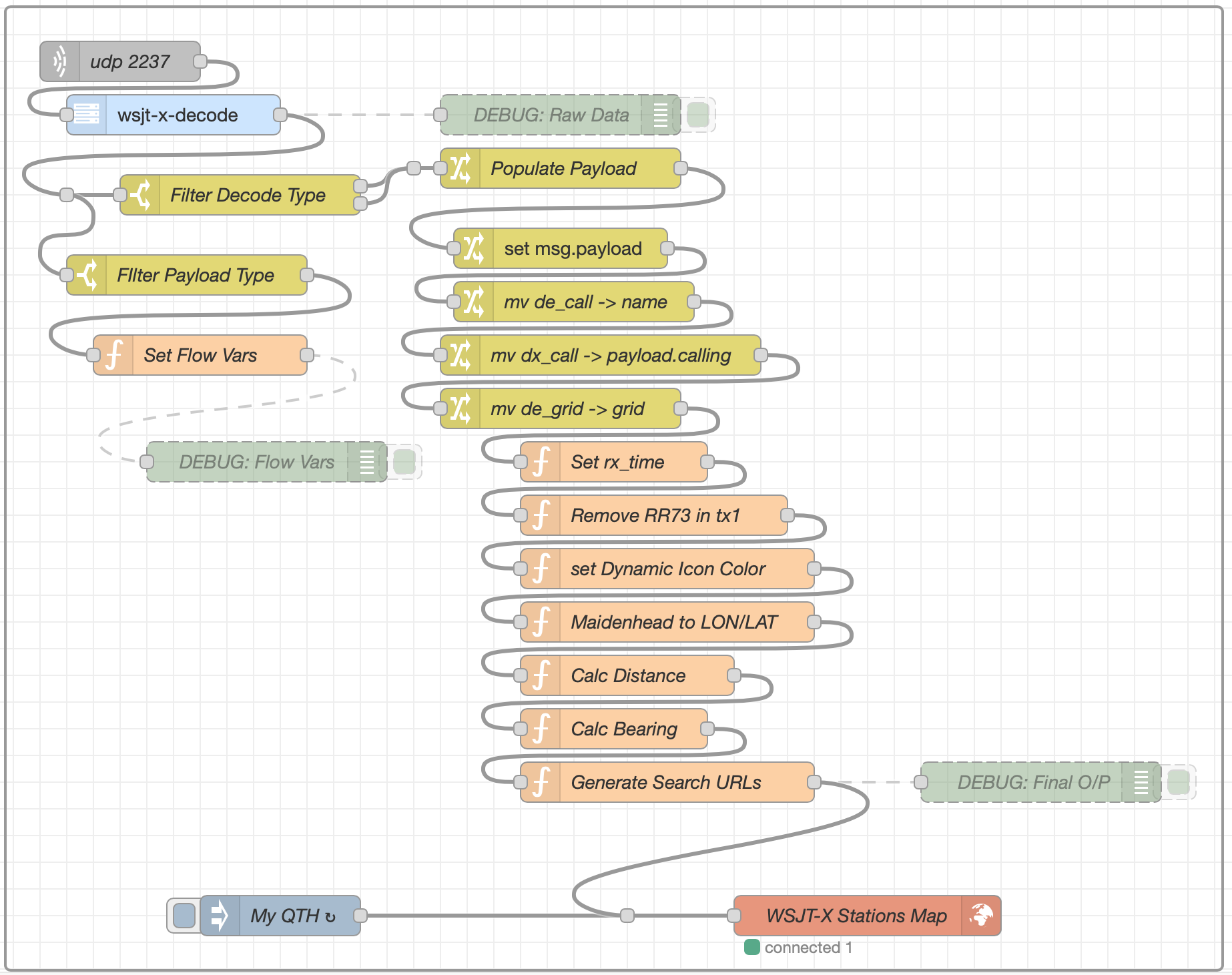
Realtime WSJT-X Decode Map v2

Following on from my initial article on plotting realtime WSJT-X decodes on a Node Red map I’ve made a few enhancements to the flow so that it includes even more data then before.

The additions to the flow now enables collection of status information from WSJT-X so that the flow is able to capture the frequency that the radio is tuned to and also the mode that WSJT-X set to. Neither of these two bits of data are in the decode message payload and so a separate mini-flow has to be created to collect the data from the status payload along side the other main flow.

Node Red flow showing additional sub flow in the top left corner of the flow editor screen

Since the status information needs to be available to all other flows I used flow variables to store the status information in so that it can be addressed directly from any of the other flows in the Node Red app.

If you’d like to use the flow in your radio room then I have put a download link below for a file that you can import into Node Red and build the flow in an instant.

More soon …