Following on from my last article on improving the Heltec ESP32 v3 antennas I found during the installation of the 90 degree SMA connector that the device was very sensitive to stray capacitance from things around it. After reconnecting my VNA I found the SWR curve would change substantially depending on what the device was near and so I set about rectifying this.
I decided to remove all the insulation from the single radial inside the unit and then added two more radials to increase the ground for the antenna to tune against. I then removed the N type plug with the antenna connected to it and made a new antenna from a piece of 1.5mm solid core insulated mains wire connected directly to the N type socket, without using an N type plug. Tuning to resonance was much easier than before and I soon had the SWR down to 1.2:1. Moving the device around and placing near to other objects the SWR curve was now much more stable than before with only very slight changes in curve shape.
M0AWS Updated 868Mhz Antenna
Making this change to the 868Mhz antenna has shown an improvement in signal strength from my node-1 device of almost +0.5dB, every dB counts when you only have 100mW to play with!
The Bluetooth antenna update has made a massive improvement to the usability of the device via the iOS Meshtastic app. Being able to have a reliable, solid connection from anywhere in the house is great and I no longer lose messages because I’ve strayed outside the range of the Bluetooth connection.
I now have 2 new Heltec ESP32 v3 devices on the way to me and will be getting those configured and operational outside with external antennas in the hope of hearing some nodes locally to me.
The Heltec ESP32 v3 LORA devices have a coil type Bluetooth/Wifi antenna on the PCB from the factory. This antenna doesn’t work particularly well and has very limited range so, I decided to do something about it.
Getting out the calculator a quarter wave at 2400Mhz is 29.7mm. Looking at the coil antenna on the PCB I decided the best way to connect the new antenna would be to solder it to the coil of the existing antenna. This would short out the coil completely whilst creating a solid mount point for the new antenna.
After a little measuring I decided to use a 31mm long piece of 1.5mm hard core mains cable for the new antenna. I stripped back the insulation from one end of the wire so that the exposed copper wire was exactly the length to short across all the windings of the coil antenna on the PCB.
Attaching replacement Bluetooth Antenna to the Heltec ESP32 v3 Device
Attaching the the wire to the coil was easy enough to do but, it’s worth pointing out that you need to be quick so that the heat doesn’t transfer down onto the PCB desoldering the coil antenna from the device.
Whilst tinkering with the Bluetooth antenna I decided I would also make a neat little quarter wave 868Mhz vertical antenna for this device whilst I had it all apart. This is my Meshtastic node-2 and it’s sole purpose is to allow me to use my iPad to send/receive messages via bluetooth which are then forwarded on to my base node-1 in the house. Node-1 is connected to the house wifi and the Meshtastic MQTT server. This combination allows me to message people on the mesh even though there are no local nodes within RF range.
Running the numbers for the 868Mhz antenna the vertical will need to be around 82.1mm long with a radial of similar length. I had to hand a very nice SMA to N Type chassis mount socket that would be ideal to mount the antenna to the case. I drilled out the holes in the case, measured out the wires and attached it all to the case. Connecting the antenna to the N Type socket I connected my VNA and set about tuning the antenna to resonance.
M0AWS Hidden Radial for the 868Mhz Heltec Antenna
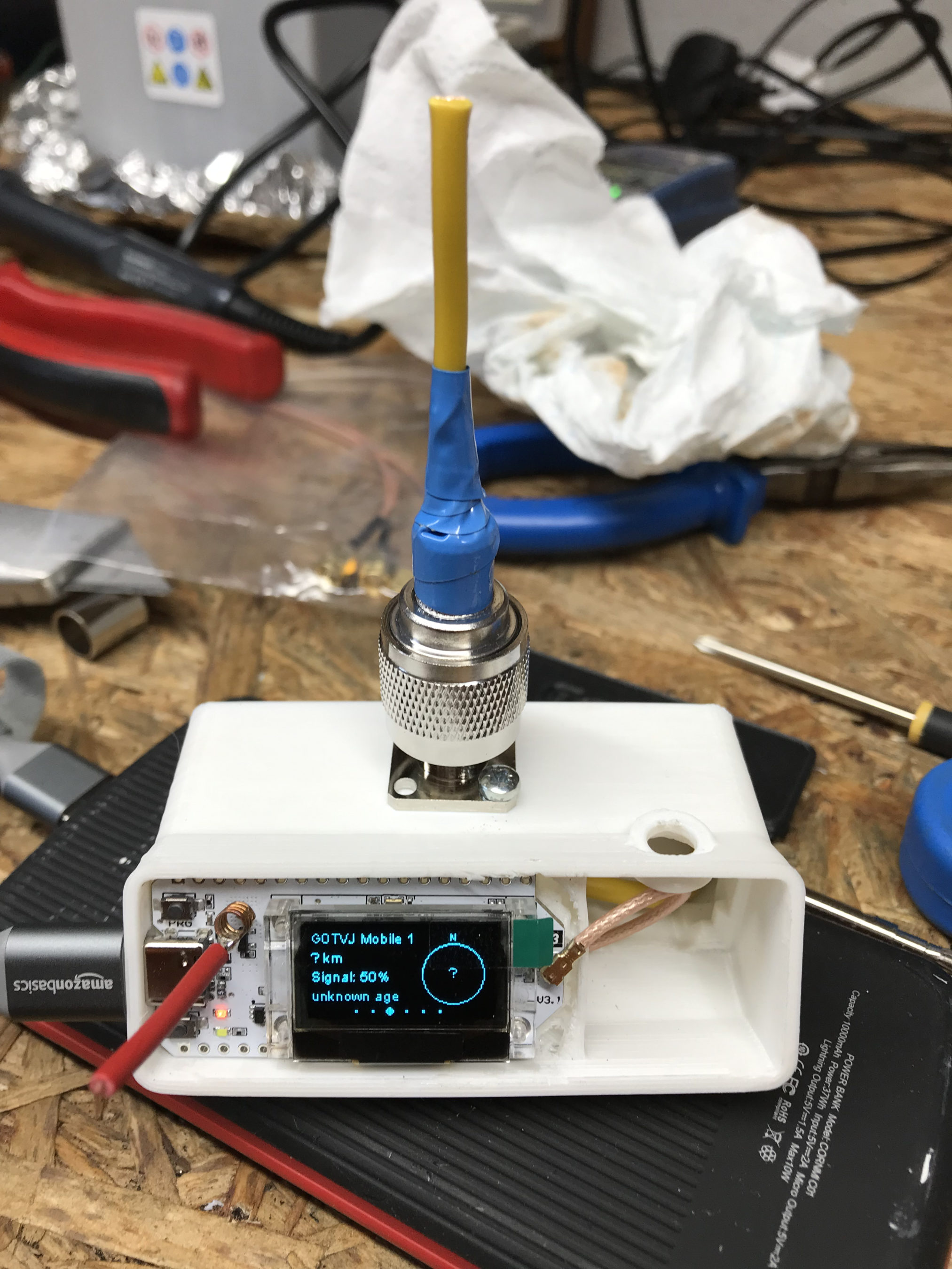
Squeezing the radial and SMA connector into the case I realised I really could do with a 90 degree SMA connector so, I quickly ordered one from Amazon which will be delivered tomorrow. Connecting up my VNA, I had to trim the antenna down to get it to resonance. The SWR ended up at 1.2:1 which is ideal. I ended up cutting off more wire than I thought I would to get the antenna to resonance but, this is due to the extra capacitance caused by the insulation on the wire. If I had used bare copper wire then I wouldn’t of had to cut so much off. I eventually ended up with around 72.9mm of wire for both the antenna and radial.
M0AWS Heltec ESP32 v3 Device with replacement Bluetooth and 868Mhz Antennas
Putting the device back into the case and connecting the USB battery the device fired up and immediately connected to my node in the house. Checking the signal strength of node-1 in the house I could see a 7dB increase in signal strength compared to the little wire antenna that comes with the device. This is a significant improvement for such a simple antenna and well worth the effort.
Next I had to drill a hole in the front of the Heltec case so that the Bluetooth antenna could poke out the front and be bent up vertically. This worked out really well and improved the Bluetooth range massively.
M0AWS Completed alterations to the Heltec ESP32 v3 antennas
Putting the node back in the house and taking my iPad down to the end of the garden some 30m away I could instantly connect to the device via Bluetooth from my iPad, something I’d not been able to do prior to adding the new antennas. I can now use the Heltec device via Bluetooth from anywhere in the house or garden making it much more accessible.
It’s amazing the difference an hour and two little pieces of wire can make to these devices and is well worth the effort.
Meshtastic is a relatively new thing in the internet of things (IOT) world and is gaining traction in the U.K. at the moment.
So what is Meshtastic?
Meshtastic is an open source, off-grid, decentralised mesh network built to run on affordable, low-power devices on the 868Mhz industrial, scientific, and medical (ISM) band. (Some devices can also run on the 433Mhz 70cm HAM band.)
The ISM band is licence free but, has limits on the RF power levels that can be used. The one plus over the HAM bands is that you can legally transfer encrypted messages over the ISM band making it secure.
The best way to think of Meshtastic is a radio version of the online decentralised Matrix chat system but, without the large server requirements and ever growing database!
Heltec ESP32 v3 Wifi, Bluetooth and 868Mhz device for Meshtastic
There are quite a few Meshtastic compatible devices on the market today with many costing around the £20 mark whilst others like the LillyGo T-Echo costing over £100 in the U.K. even though they are less than half the price in the USA.
Since I’m just starting out on my Meshtastic adventure I thought I’d start with a pair of Heltec ESP32 v3 devices that are normally readily available on Amazon but, due to the current push to build a U.K. wide mesh, they are currently out of stock pretty much everywhere.
Loading the Meshtastic firmware onto the devices is fairly straight forward and can be done using the web installer via either the Edge or Chromium web browsers. (Note: If using Windows O/S you will need to install some drivers from the Meshtastic website to be able to communicate with the devices)
Having neither of the two browsers and being a Linux command line junkie I decided to use the Python programme to load the firmware onto the two devices. It’s worth noting that you don’t need any drivers to be able to communicate with the devices if you’re using either Debian or one of the many Ubuntu flavours of Linux O/S.
Using the Python command line program sounds like a more complicated approach but, in reality it’s super simple, extremely reliable, quick and if like me you use a Linux PC in the radio shack then you most likely already have most of what you need to get the job done. Just follow the simple steps as laid out on the Meshtastic web site and you’ll have the firmware loaded in no time at all.
Installing the Meshtastic firmware onto my Heltec ESP32 v3 using the Python command line tool
The firmware takes less than a minute to copy across to the Heltec device and is automatically rebooted ready for configuration once the transfer has completed.
It is possible to configure the device via the command line tool however, since there is a nice GUI app for both Apple iOS and Android devices I decided to install the Meshtastic app on my iPad and connect to the device via Bluetooth to configure it.
Once you’ve got the Meshtastic app installed on your device and have connected via Bluetooth you’ll be ready to start configuring the device to join the mesh. The first thing you want to do is set the region. This is different in each country but, in the UK we use the EU_868 region settings. This will set the device to use the 868Mhz ISM band which is the band being used to build the U.K. wide mesh.
View of the Meshtastic app on iOS showing the configuration options for the Heltec ESP32 v3
There is a multitude of configuration options within the app which I will go into in greater detail in a series of articles at a later date.
Heltec ESP32 v3 running Meshtastic Firmware
For those of you that, like me aren’t near any other nodes you can connect the devices to the internet and use the Meshtastic MQTT server to communicate with other nodes. This of course isn’t off-grid but, it will get you started until the mesh grows into your local area at which point your device will automatically start communicating with the other nodes over radio.
Meshtastic MQTT connectivity
Once you are connected to either the MQTT server or other nodes via radio you will see the other node details appear in the Meshtastic app. It’s interesting to look at the information and see signal strengths and traffic levels etc for each node.
View of the Meshtastic app on iOS showing Nodes in the Mesh and Device Metrics for the M0AWS-1 Node
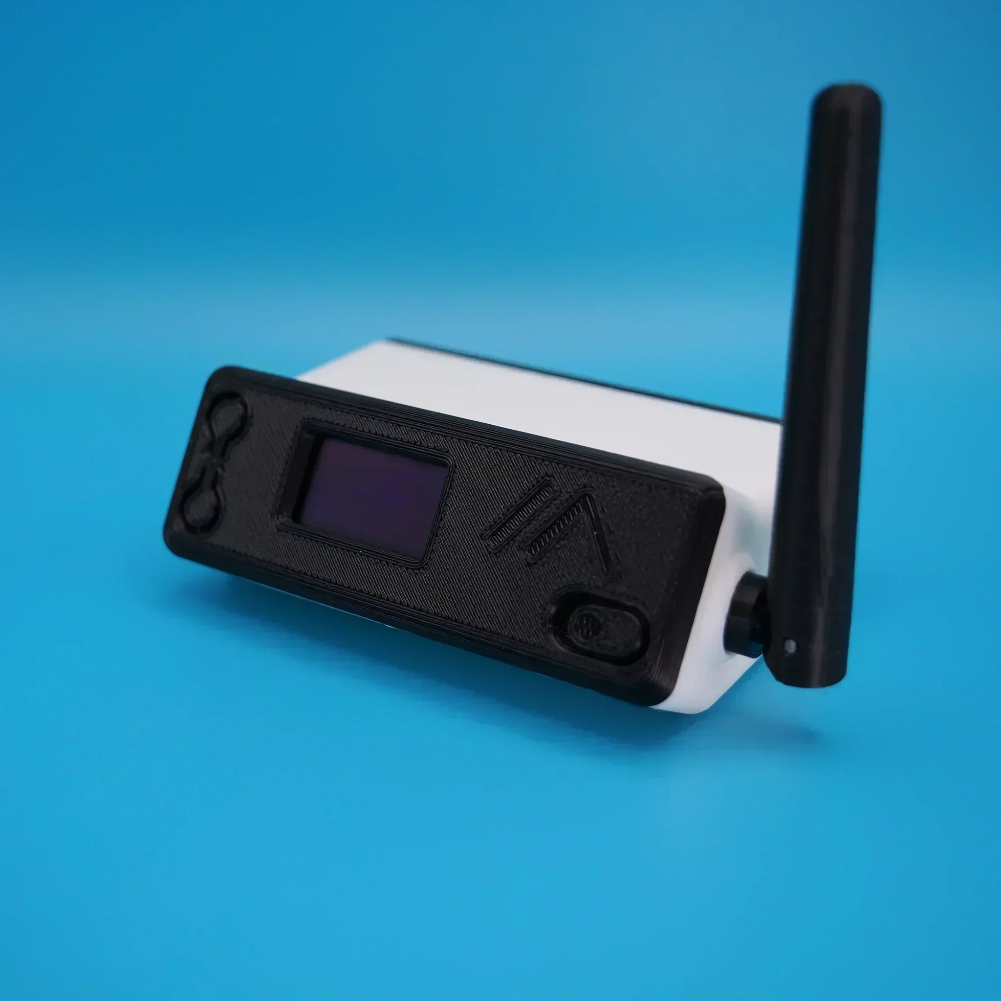
There are a multitude of cases available for the Heltec v3 devices, especially if you have access to a 3D printer. One of the nicest cases I have seen is the Bender from IKB3D (I know, it’s a strange name!) but, it really is a super little case for the Heltec series of devices.
Bender case for Heltec ESP32 v3 devices
You can either buy the 3D print files for £8.99 and print it yourself or just order a pre-printed and assembled case directly from the website although, due to demand there is a long lead time currently.
Since setting up the new HAM station here in the UK the one band I’ve not yet got back onto is 160m, one of my most favourite bands in the HF spectrum and one that I was addicted to when I live in France (F5VKM).
Having such a small garden here in the UK there is no way I can get any type of guyed vertical for 160m erected and so I needed to come up with some sort of compromise antenna for the band.
Only being interested in the FT4/8 and CW sections of the 160m band I calculated that I could get an inverted-L antenna up that would be reasonably close to resonant. It would require some additional inductance to get the electrical length required and some impedance matching to provide a 50 Ohm impedance to the transceiver.
Measuring the garden I found I could get a 28m horizontal section in place and a 10m vertical section using one of my 10m spiderpoles. This would give me a total of 38m of wire that would get me fairly close to the quarter wave length.
For impedance matching I decided to make a Pi-Network ATU. I’ve made these in the past and found them to be excellent at matching a very wide range of impedances to 50 Ohm.
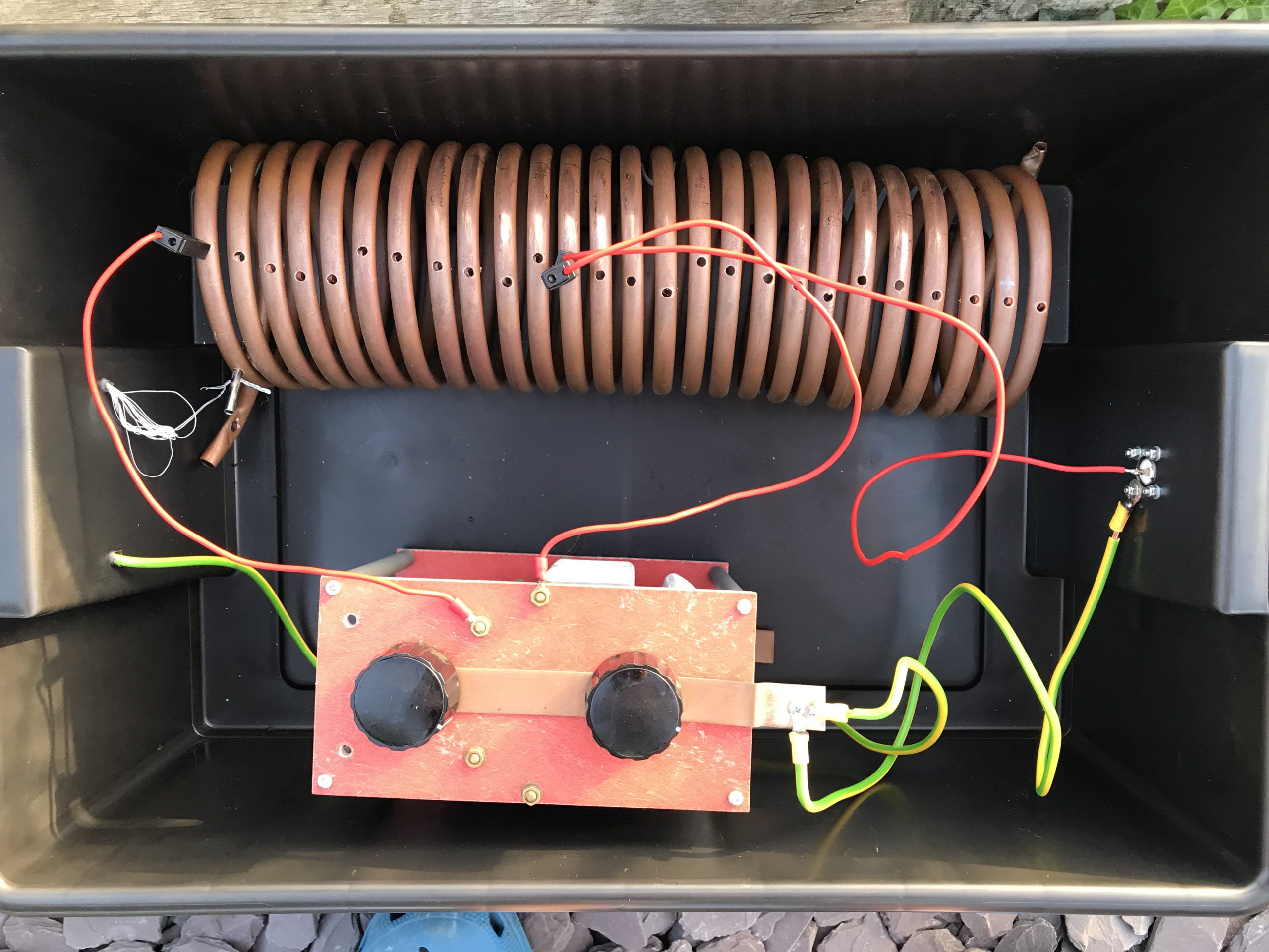
M0AWS Homebrew Pi-Network ATU
Since I still had the components of the Pi-Network ATU that I built when I lived in France I decided to reuse them as it saved a lot of work. The inductor was made from some copper tubing I had left over after doing all the plumbing in the house in France and so it got repurposed and formed into a very large inductor. The 2 x capacitors I also built many years ago and fortunately I’d kept locked away as they are very expensive to purchase today and a lot of work to make.
Getting the Inverted-L antenna up was easy enough and I soon had it connected to the Pi-Network ATU. I ran a few radials out around the garden to give it something to tune against and wound a 1:1 choke balun at the end of the coax run to stop any common mode currents that may have appeared on the coax braid.
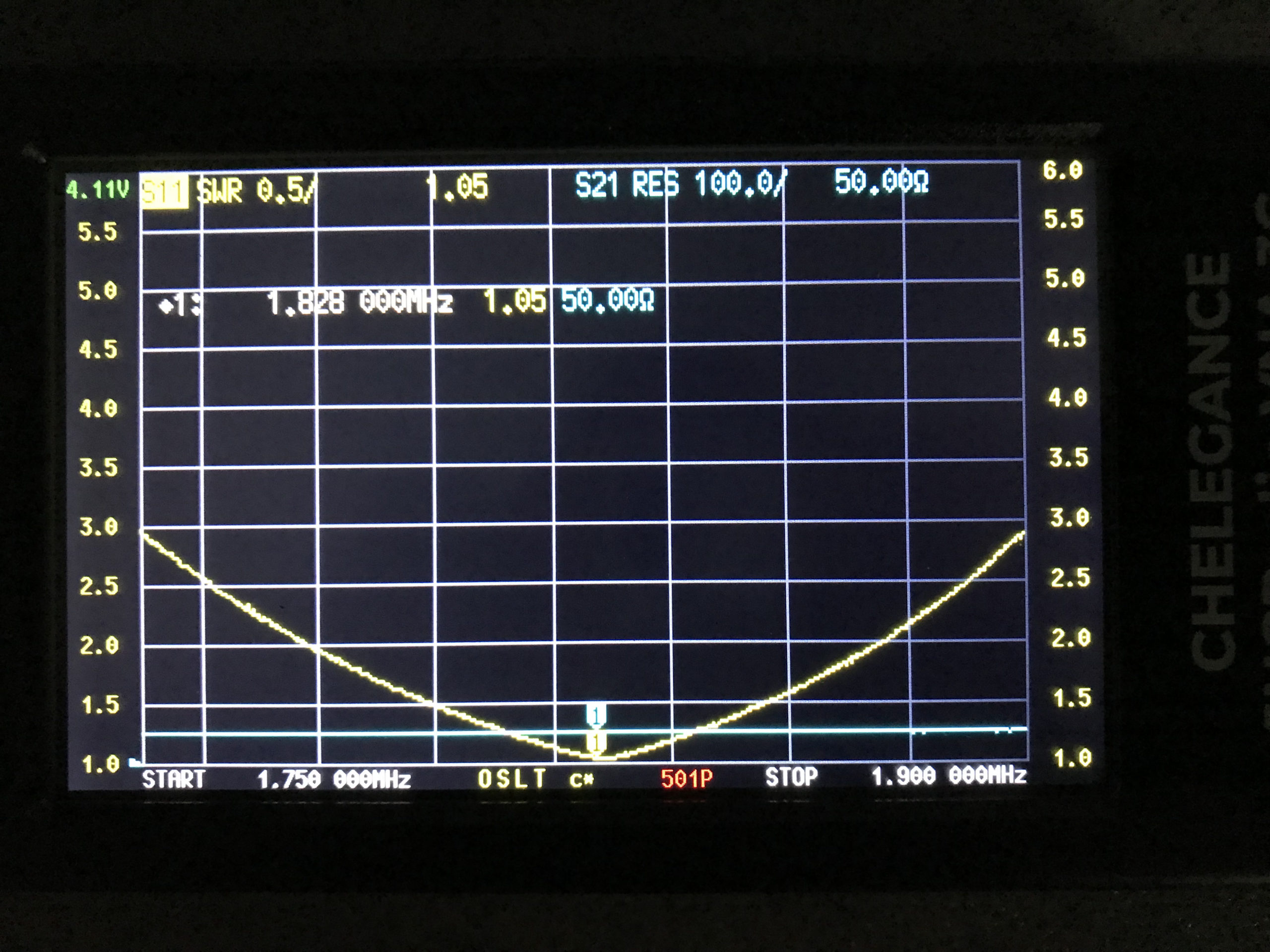
Connecting my JNCRadio VNA I found that the Inverted-L was naturally resonant at 2.53Mhz, not too far off the 1.84Mhz that I needed. Adding a little extra inductance and capacitance via the ATU I soon had the antenna resonant where I wanted it at the bottom of the 160m band.
M0AWS 160m Inverted L Antenna SWR Curve
With the SWR being <1.5:1 across the CW and FT8 section of the band I was ready to get on 160m for the first time in a long.
Since it’s still summer in the UK I wasn’t expecting to find the band in very good shape but, was pleasantly surprised. Switching the radio on before full sunset I was hearing stations all around Europe with ease. In no time at all I was working stations and getting good reports using just 22w of FT8. FT8 is such a good mode for testing new antennas.
As the sky got darker the distance achieved got greater and over time I was able to work into Russia with the longest distance recorded being 2445 Miles, R9LE in Tyumen Asiatic Russia.
In no time at all I’d worked 32 stations taking my total 160m QSOs from 16 to 48. I can’t wait for the long, dark winter nights to see how well this antenna really performs.
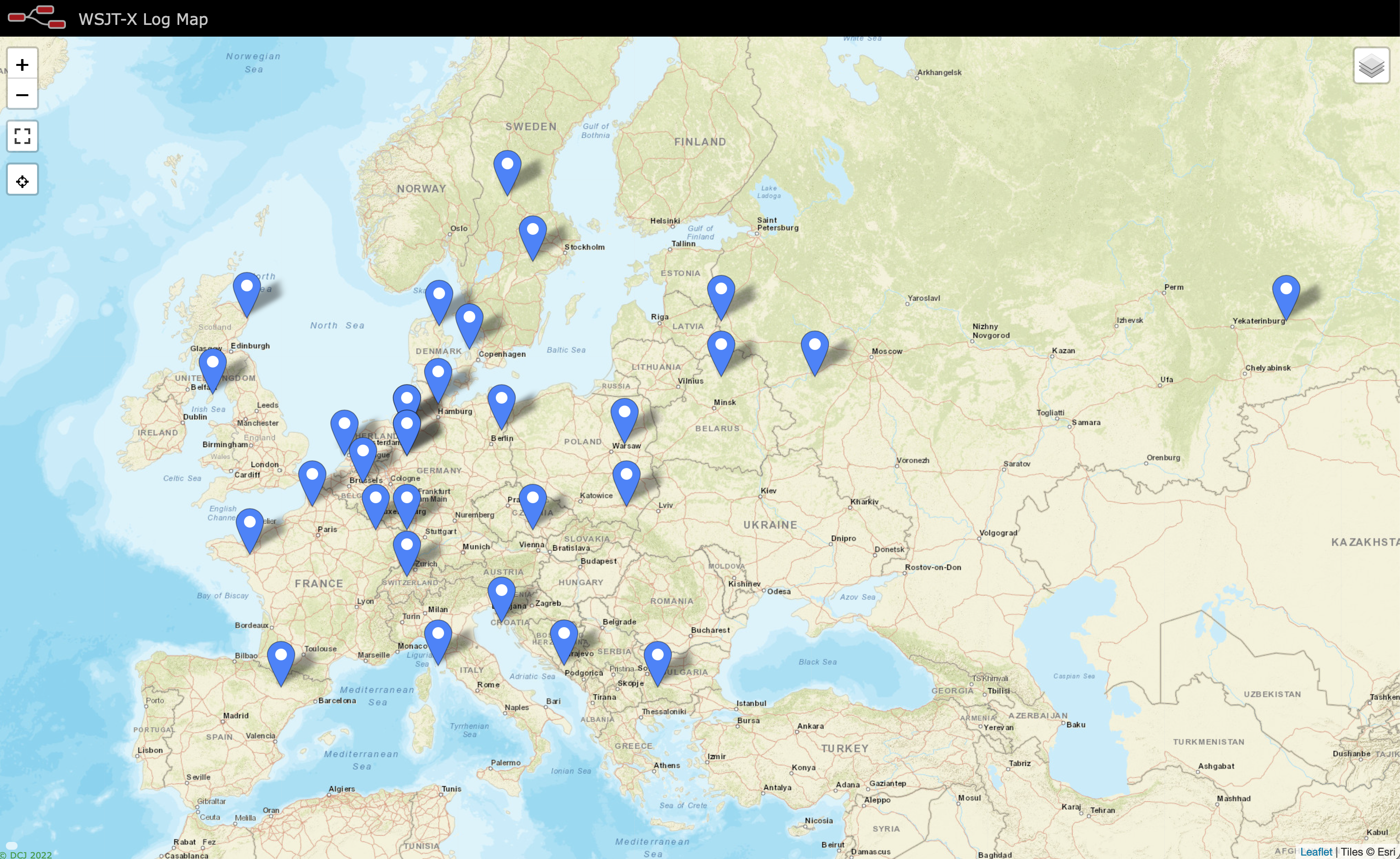
M0AWS Map showing stations worked on 160m using Inverted L Antenna
The map above shows the locations of the stations worked on the first evening using the 160m Inverted-L antenna. As the year moves on and we slowly progress into winter it will be fun to start chasing the DX again on the 160m band..
UPDATE 6th October 2023. Been using the antenna for some time now with over 100 contacts on 160m. Best 160m DX so far is RV0AR in Sosnovoborsk Asiatic Russia, 3453 Miles using just 22w. Pretty impressive for such a low antenna on Top Band.
I’ve been making a few improvements to my QO-100 Node Red Dashboard whilst waiting for the 2.4Ghz hardware to arrive. I’ve added the ability to split the RX and TX VFOs so that I can tune away from the TX frequency for working split stations or for tuning to slightly off frequency stations. I also added a series of tuning buttons to the top of the GQRX side of the dashboard to enable easy tuning using the trackball connected to my Kubuntu PC. This worked well but, I really missed having a real VFO knob like a conventional radio.
As I had a Griffin Powewrmate USB VFO from a previous SDR radio I added it to the flow as well so that I had a physical VFO knob for the SDR receiver. Details on how I got it working using evtest and a simple BASH script are in the Griffin Powermate article.
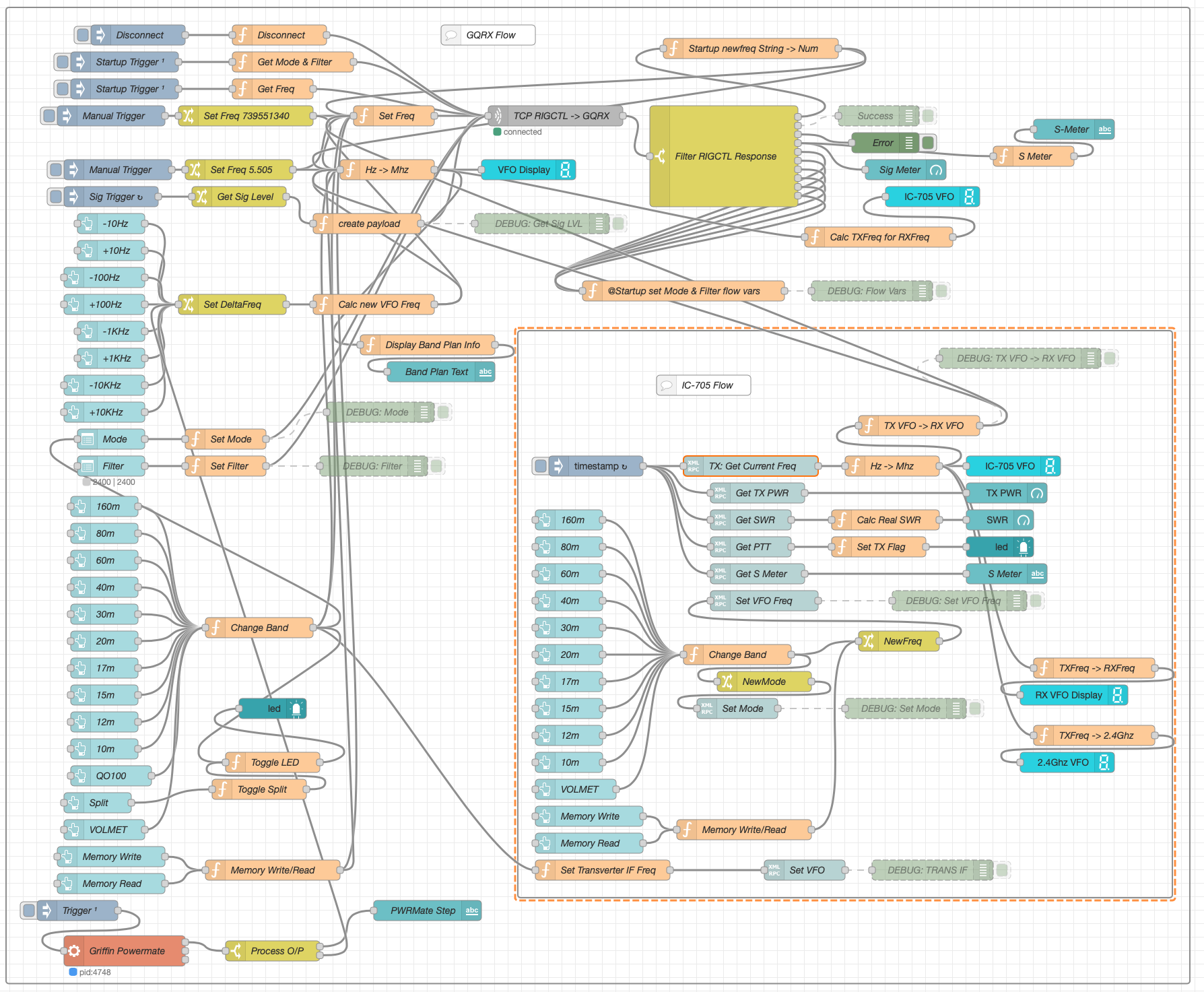
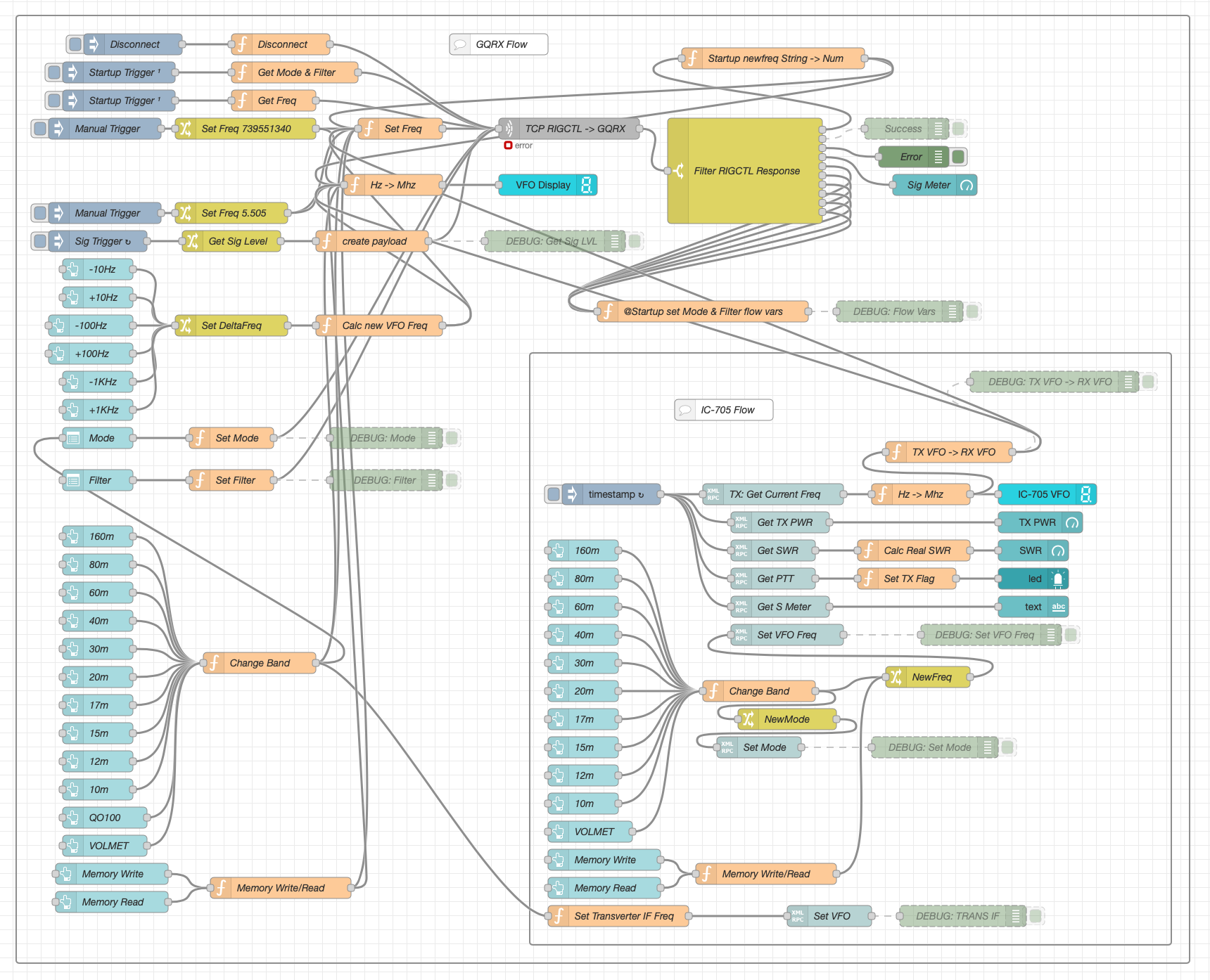
M0AWS QO-100 Node Red Dashboard Flow
The Node Red flow is looking a little busier with the addition of split mode and the Griffin Powermate USB VFO which has really enhanced the useability of the solution. It’s very impressive what can be achieved with Node Red with a little imagination. You really don’t need to be a heavy weight programmer to make things work.
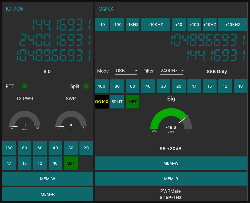
M0AWS QO-100 Node Red Dashboard as of 07/06/23
I also put together some code to calculate the S Meter reading from the dBFS data the GQRX SDR software generates. It’s not 100% accurate but, it’s close enough to be useful.
On the IC-705 side of the Dashboard I also now display the 2.4Ghz uplink frequency so that it’s available for logging.
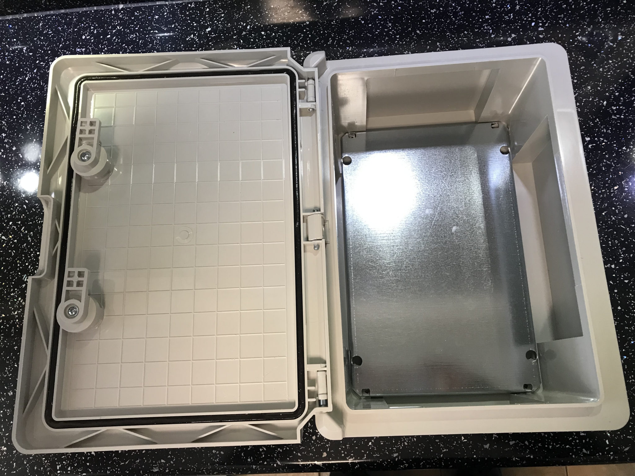
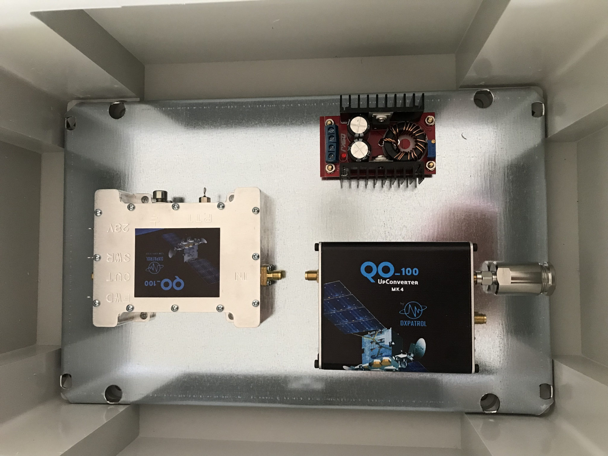
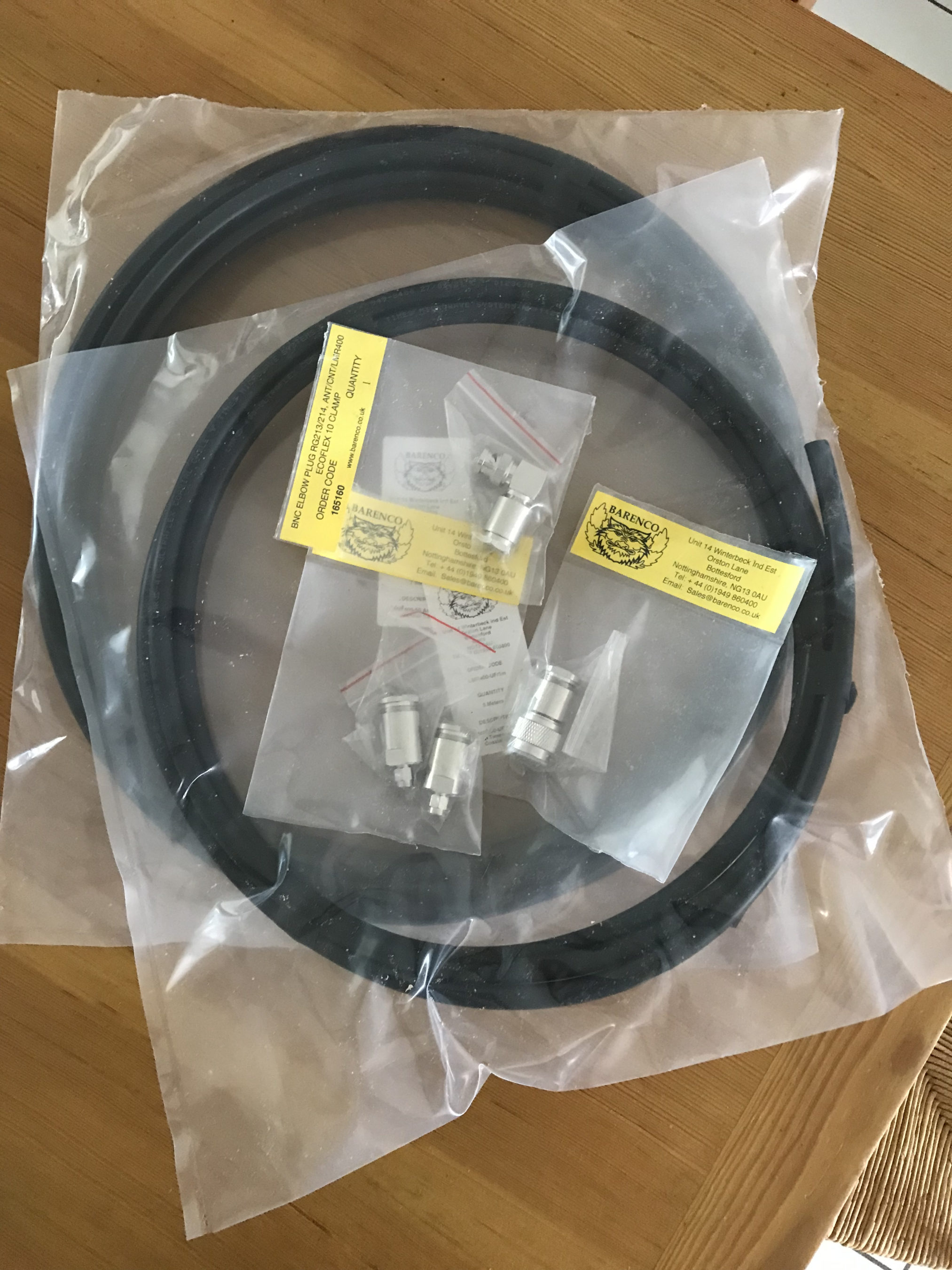
So with the QO-100 Dashboard ready to go live I have now started putting together the 2.4Ghz transmit path of the ground station. I have the 2.4Ghz transverter and matching 12w amplifier from DXPatrol, the IceCone Helix 2.4Ghz antenna from Nolle Engineering, some LMR-400-UF and connectors from Barenco and an appropriate water proof enclosure from Screwfix to fit all the kit into however, I’m now being held up by one simple little SMA male to SMA male connector that I need to connect the transverter and amp together.
M0AWS Waterproof enclosure from ScrewfixM0AWS Laying out the 2.4Ghz TX kit in the enclosureM0AWS LMR-400-UF coax from Barenco
The SMA connector has been ordered but, is taking a month of Sundays to arrive! Hopefully it’ll arrive soon and I’ll finally get on the QO-100 satellite and start enjoying the fun.
I’ve been gradually building my QO-100 ground station over the last few months and have had the receive path working for some time now. One of the things I really miss with the Funcube Dongle Pro+ (FCD) SDR is a real VFO knob for changing frequency.
My QO-100 Node Red dashboard is configured so that I can have the FCD track the uplink frequency from the IC-705 but, sometimes I use the FCD without the IC-705 in the shack and so a physical VFO would be handy.
Many years ago when I lived in France (F5VKM) I had a Flexradio Flex-3000 SDR, a great radio in it’s time and one that gave me many hours of enjoyment. One addition I bought for that station was a Griffin Technology Powermate VFO knob. It worked extremely well with the PowerSDR software for the Flex-3000 and I used it for many years.
Many years later I’m back in the UK and much of my equipment is packed away in the attic, including the Griffin Technology Powermate VFO.
I decided to dig it out and see if I could get it working with GQRX SDR software. Sadly I couldn’t get it working with GQRX however, I did find a way of getting it working with Node Red and thus could add it to my QO-100 Node Red Dashboard and then control GQRX with it via a simple Node Red flow.
Griffin Technology Powermate VFO
Plugging the Powermate VFO into my Kubuntu PC it wasn’t immediately recognised by the Linux O/S. After a little searching I found the driver on Github. I added the PPA to my aptitude sources and installed the driver using apt.
Once installed the default config for the Powermate device is to control the default audio device volume. To make the device available for use as a VFO knob you need to change the configuration so that the default setting is disabled. To do this is relatively easy, just edit the config file using your favourite command line editor (Vi/Vim in my case) and add the following entry.
vi /etc/powermate.toml

# Entry to control HDMI volume with Powermate
#sink_name = "alsa_output.pci-0000_01_00.1.hdmi-stereo"

# Set powermate not to work with volume control
sink_name = ""
As shown above, comment out the default “sink_name” entry (Yours may be different depending on audio device in your PC) and add in the Powermate “sink_name” entry that effectively assigns it to nothing.
Once this is done, save the file and exit your editor and then reboot the PC.
Next you’ll need to install a small program called evtest.
sudo apt install evtest
To check the evtest program has installed correctly, plugin your Powermate VFO to any available USB port and run the following command in a terminal.
evtest /dev/input/powermate
Turning the Powermate knob you should see output on the screen showing the input from the device. You should also see BTN events for each press of the Powermate device.
Input driver version is 1.0.1
Input device ID: bus 0x3 vendor 0x77d product 0x410 version 0x400
Input device name: "Griffin PowerMate"
Supported events:
  Event type 0 (EV_SYN)
  Event type 1 (EV_KEY)
    Event code 256 (BTN_0)
  Event type 2 (EV_REL)
    Event code 7 (REL_DIAL)
  Event type 4 (EV_MSC)
    Event code 1 (MSC_PULSELED)
Properties:
Testing ... (interrupt to exit)
Event: time 1685816662.086666, type 2 (EV_REL), code 7 (REL_DIAL), value -1
Event: time 1685816662.086666, -------------- SYN_REPORT ------------
Event: time 1685816662.318638, type 2 (EV_REL), code 7 (REL_DIAL), value -1
Event: time 1685816662.318638, -------------- SYN_REPORT ------------
Event: time 1685816662.574615, type 2 (EV_REL), code 7 (REL_DIAL), value -1
Event: time 1685816662.574615, -------------- SYN_REPORT ------------
Event: time 1685816663.670461, type 2 (EV_REL), code 7 (REL_DIAL), value 1
Event: time 1685816663.670461, -------------- SYN_REPORT ------------
Event: time 1685816664.030421, type 2 (EV_REL), code 7 (REL_DIAL), value 1
Event: time 1685816664.030421, -------------- SYN_REPORT ------------
Event: time 1685816664.334389, type 2 (EV_REL), code 7 (REL_DIAL), value 1
Event: time 1685816664.334389, -------------- SYN_REPORT ------------
Event: time 1685816665.334255, type 1 (EV_KEY), code 256 (BTN_0), value 1
Event: time 1685816665.334255, -------------- SYN_REPORT ------------
Event: time 1685816665.558230, type 1 (EV_KEY), code 256 (BTN_0), value 0
Event: time 1685816665.558230, -------------- SYN_REPORT ------------
Event: time 1685816666.030161, type 1 (EV_KEY), code 256 (BTN_0), value 1
Event: time 1685816666.030161, -------------- SYN_REPORT ------------
Event: time 1685816666.182151, type 1 (EV_KEY), code 256 (BTN_0), value 0
Event: time 1685816666.182151, -------------- SYN_REPORT ------------
At this point you’re ready to stop evtest (CTRL-C) and then create the following little BASH shell script that Node Red will run to collect the O/P from the Powermate USB device.
#!/bin/bash

###############################################
# Griffin Technology Powermate control script #
# for Node Red.                               #
#                                             #
# 04/06/23 - M0AWS - v0.1                     #
#                                             #
###############################################

VAL="1"
echo "STEP-1Hz"

/usr/bin/evtest /dev/input/powermate | while read LINE
do
   case $LINE in

      *"(REL_DIAL), value 1") echo "$VAL"
           ;;

      *"(REL_DIAL), value -1") echo "-$VAL"
           ;;

      *"(BTN_0), value 1") case $VAL in

                              "1") VAL="10"
                                   echo "STEP-10Hz"
                                      ;;

                             "10") VAL="100"
                                   echo "STEP-100Hz"
                                      ;;

                             "100") VAL="1000"
                                    echo "STEP-1Khz"
                                       ;;

                             "1000") VAL="10000"
                                     echo "STEP-10Khz"
                                         ;;

                             "10000") VAL="1"
                                       echo "STEP-1Hz"
                                          ;;
                              esac
                                 ;;
        esac
done
Once the BASH script is copied and pasted into a file called powermate.sh you need to make it executable by using the following command.
chmod 700 ./powermate.sh
If you now run the shell script in a terminal you’ll see a similar output to that shown below from the device when used.
As you can see above the shell script outputs a positive or negative number for VFO tuning and changes the VFO step size each time the Powermate is depressed.
Getting this output from the BASH shell script into Node Red is really simple to achieve using just 3 or 4 nodes.
In the Node Red development UI create the following nodes.
Griffin Powermate Node Red Nodes
The first node in the flow is a simple inject node, here I called it trigger. This sends a timestamp into the next node in the flow at startup to set the flow running.
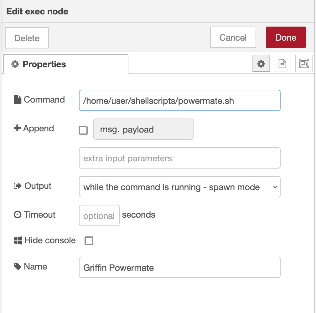
The Griffin Powermate node is a simple exec node that runs the script we created above.
M0AWS Powermate exec node
Configure the node as shown above and connect it to the inject node that’s used as a trigger. Note: Change “user” in the Command field shown above to that of your username on your Linux PC)
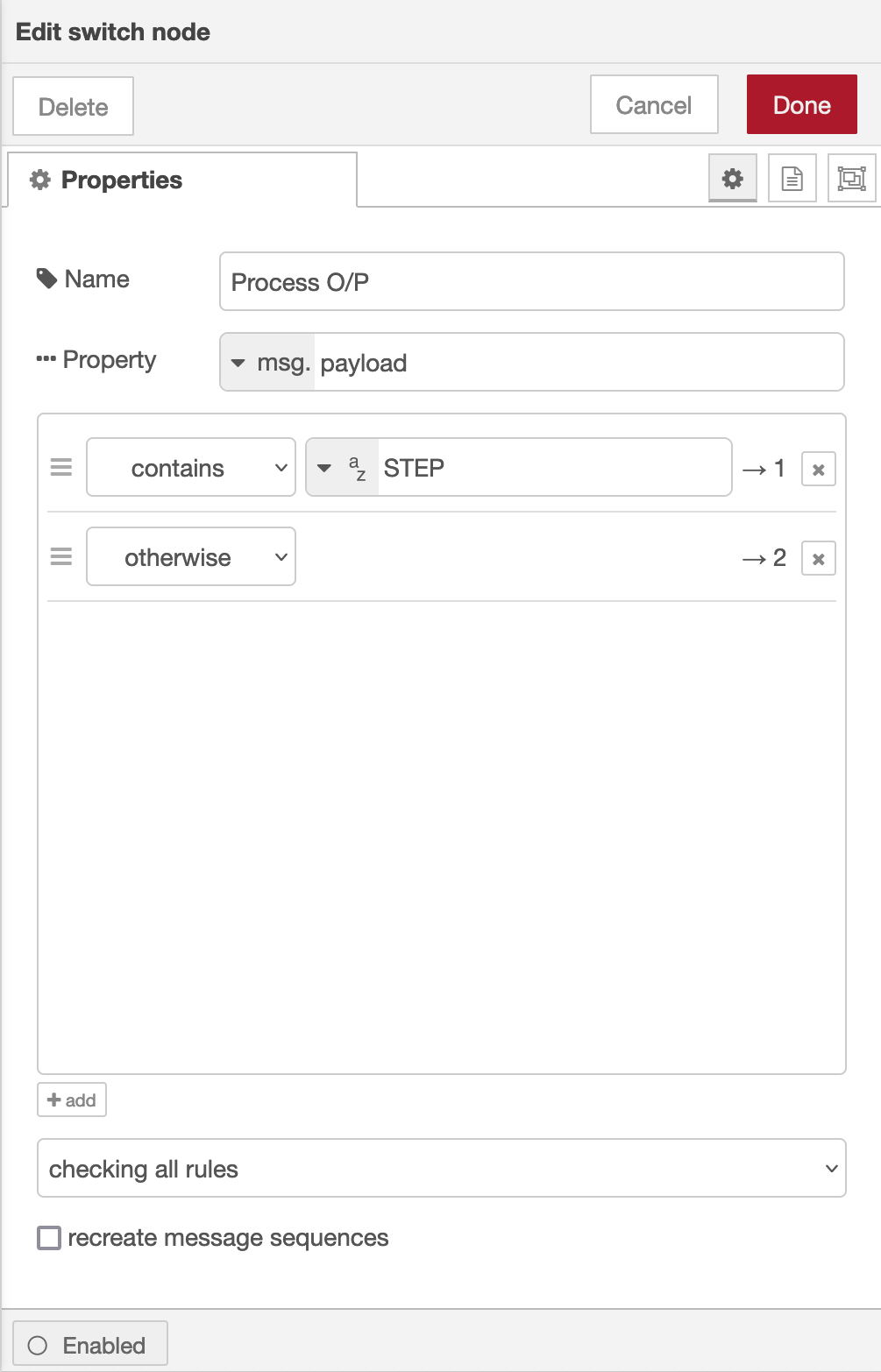
Once done create the third node in the flow, a simple switch node and configure as shown below.
Switch Node for Powermate
The switch node has two outputs, the top one is a text output that is fed into a text field to show the current step size of the Powermate device and the lower output is the numeric output that must be fed into your VFO control flow so that the VFO value is incremented/decremented by the amount output by the Powermate device.
I’ve found the Griffin Technology Powermate USB device works extremely well with Node Red and GQRX that I use for controlling the FCD SDR radio and it’s now part of my QO-100 ground station build.
M0AWS QO-100 Dashboard with Powermate Step Display at bottom
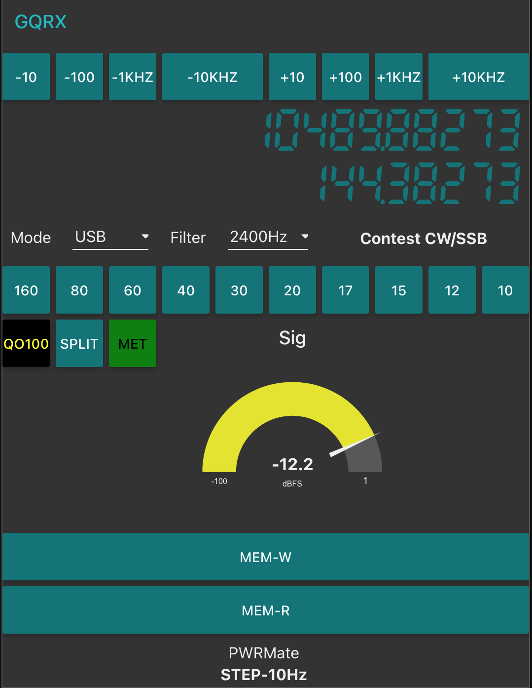
As shown above you can see the Powermate Step size at the bottom of the dashboard, this text changes each time the Powermate device is depressed and will set a step size of 1Hz, 10Hz, 100Hz, 1Khz, 10Khz in a round-robin fashion.
The next stage of the build is the 2.4Ghz transmit path. I now have all the necessary hardware and so this part of the build can finally commence.
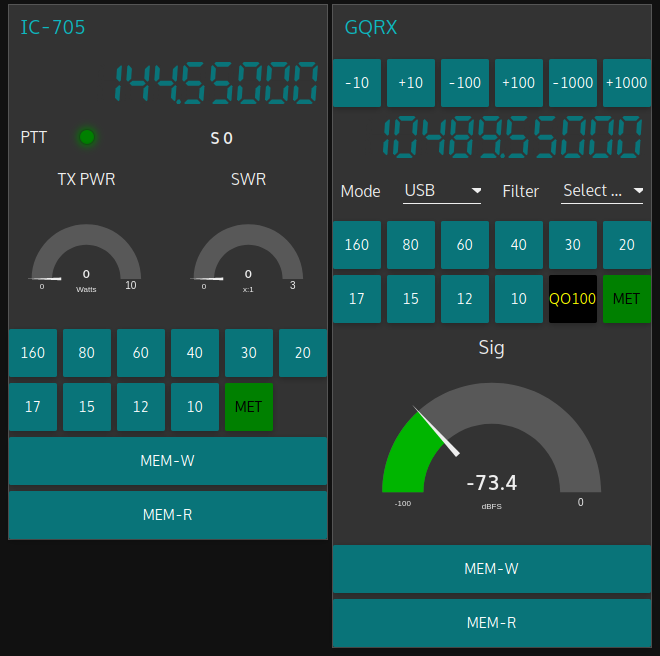
I’ve now completed the GQRX Receive and Icom IC-705 Transmit dashboard in Node Red. It was a fun project to put together and needed some javascript coding to get the functionality I wanted but, I got there in the end.
M0AWS QO-100 GQRX/IC-705 control dashboard
The dashboard looks fairly simple but, there is a lot behind the scenes to get it to this stage.
On the left is the Icom IC-705 transmit control panel. It shows the transmit frequency, power output and SWR reading. The SWR is so that I can check that the input into the 2.4Ghz transverter doesn’t have any connectivity issues. The “S0” will actually display the S Meter reading when the IC-705 is being used as a normal transceiver rather than being in QO-100 Duplex mode as shown above where the GQRX app and Funcube Dongle SDR are being used as the receiver.
The GQRX side of the dashboard shows the downlink frequency which tracks the uplink frequency of the VFO on the IC-705. This will ensure that the Funcube Dongle Pro+ SDR receiver will always be on the correct downlink frequency relative to the uplink frequency, thus I should always be able to hear my own signal coming from the QO-100 satellite.
Once taken out of QO-100 mode the two radios can be used independently on any of the HAM bands and can be switched using the buttons on the dashboard.
I also coded in a simple memory facility where a frequency can be stored in Node Red and recalled later on both the transmit and receive sides.
Looking at the dashboard it all looks simple and straight forward however, if you look at the Node Red flow it becomes obvious that this isn’t the case.
QO-100 Dashboard Flow in the Node Red Editor (Click for larger image)
There’s a lot to the flow to get the information from the receiver and transmitter so that it can be presented on the dashboard. There’s also some code to convert between Rigctl protocol used by the GQRX application and XMLRPC used by the IC-705 via FLRig and WFview. I had to also code around a bug in the Node Red XMLRPC node whereby you have to add 0.1 onto the VFO frequency for it to be passed onto the radio otherwise the information is never sent. This was a real pain of a bug to find but, with a little experimentation I found the problem and managed to code around it. The strange thing about this is that the 0.1 added onto the frequency isn’t actually passed onto the radio via the XMLRPC node, it just has to have that on input otherwise it doesn’t work at all. A very strange bug and hopefully one that will be fixed by the node developer in future releases.
All that is left to do now is add the temperature sensors dashboard to complete the dashboard. These haven’t arrived yet and so I’ve not been able to create the necessary flow to collect the data from them.
Hopefully this coming week the weather will improve and I’ll start getting the dish antenna up and the get the receive side working.
UPDATE: Further development of my QO-100 Dashboard has taken place, you can read all about it here.
Whilst I’ve been waiting for the weather to improve so that I can get my QO-100 dish antenna up I’ve been working on my QO-100 Node Red dashboard.
The idea of the dash board is to bring together the operating of the receiver and transmitter into one control centre so that the two separate devices are able to communicate and behave as if they were actually one device, like a transceiver rather than being individual components.
Ideally I would like to have the transmitter and receiver talking to each other such that when the VFO on the transmitter is incremented/decremented the receiver VFO also moves by the same amount.
By doing this the receiver VFO should always be in the right place on the 10Ghz band to hear my 2.4Ghz uplink signal and of course, any station coming back to my CQ calls.
So far I’ve only been working on the receive part of the Node Red flow, it’s certainly been a lot of fun getting it put together.
I control my Funcube Dongle Pro+ (FCD) using GQRX SDR on my Kubuntu PC. This software is working extremely well with the FCD and I’m happy with the level of functionality it offers.
GQRX SDR has the ability built in to control the SDR via remote TCP connection using RIGCTL protocol. Currently there isn’t a RIGCTL node available for Node Red so I have written a number of Javascript function nodes that provide the appropriate functionality in conjunction with a standard Node Red TCP node. This is working extremely well on the local LAN in the radio room and is proving to be very stable and responsive.
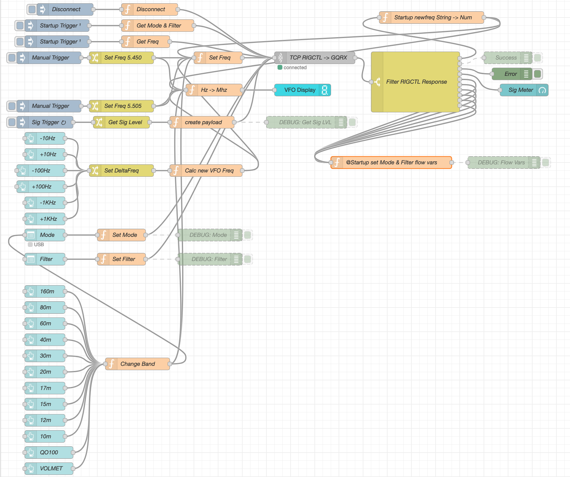
M0AWS QO-100 Node Red Flow – Receive Section
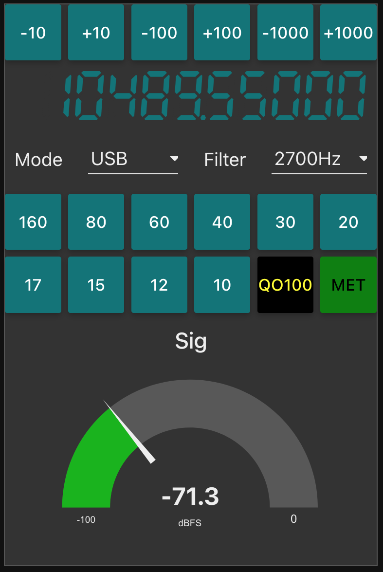
The flow for the receive section of the dashboard looks fairly complicated but, in reality it’s really not too difficult to get to grips with. The receive flow provides the facility to switch bands, switch modes, change receiver filter band width, display a realtime signal strength meter, receive +/- clarifier in 10/100/1000Hz increments and put the receiver into QO-100 mode where the SDR VFO is tuned to 739.550Mhz whilst the dashboard VFO shows the QO-100 downlink frequency in the 10Ghz band. This is all working very well and I’m happy with the initial result.
M0AWS QO-100 Receive Dashboard in QO-100 mode
I now need to start work on the transmit side of the QO-100 dashboard and get communications between my IC-705 transceiver and the FCD SDR working via Node Red. This could be a little more challenging as it will involve communicating with the IC-705 via WFView over wifi.
Following on from my initial article on plotting realtime WSJT-X decodes on a Node Red map I’ve made a few enhancements to the flow so that it includes even more data then before.
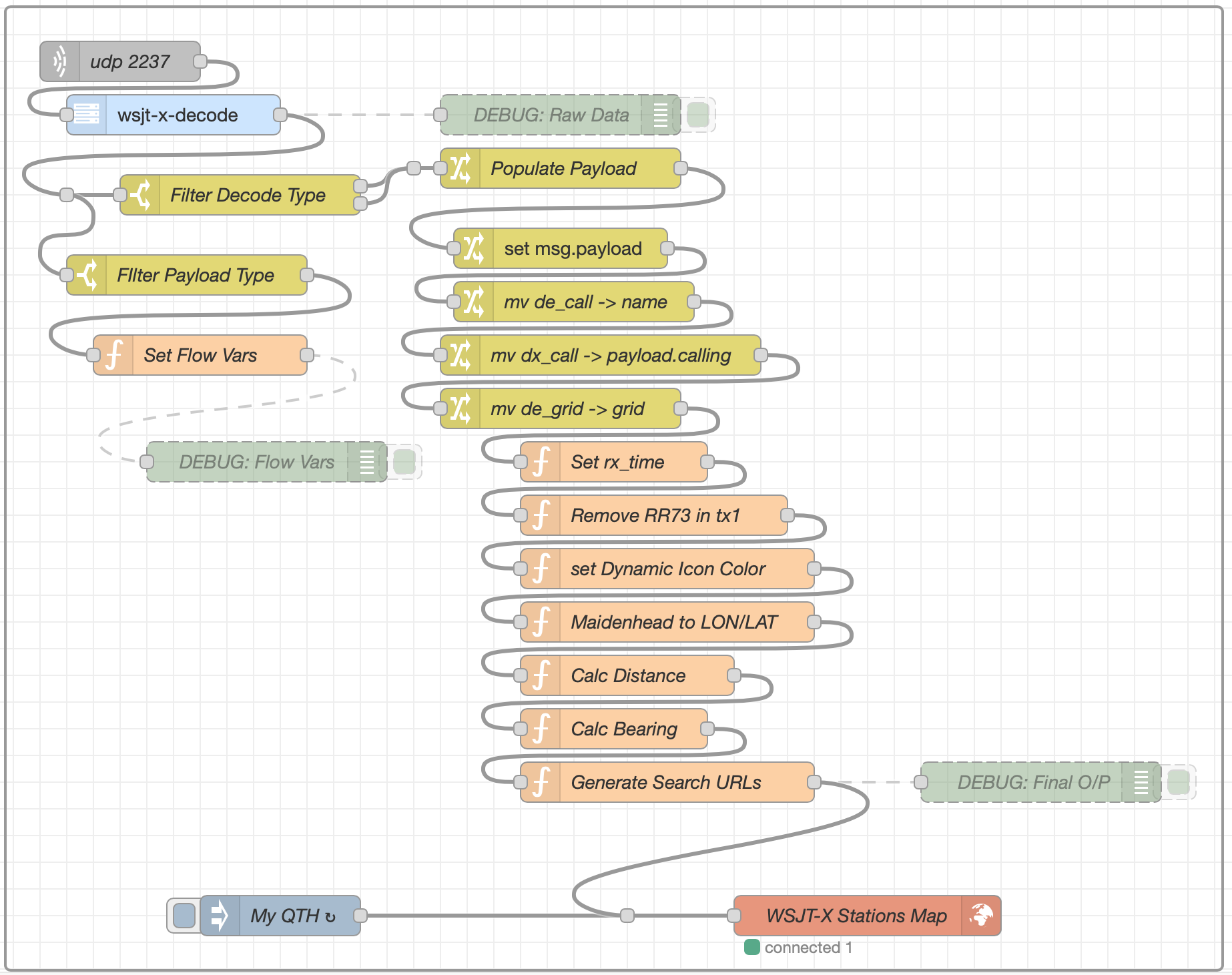
The additions to the flow now enables collection of status information from WSJT-X so that the flow is able to capture the frequency that the radio is tuned to and also the mode that WSJT-X set to. Neither of these two bits of data are in the decode message payload and so a separate mini-flow has to be created to collect the data from the status payload along side the other main flow.
Node Red flow showing additional sub flow in the top left corner of the flow editor screen
Since the status information needs to be available to all other flows I used flow variables to store the status information in so that it can be addressed directly from any of the other flows in the Node Red app.
If you’d like to use the flow in your radio room then I have put a download link below for a file that you can import into Node Red and build the flow in an instant.
Following on from my other Node Red exploits I’ve put together a flow that creates an interactive map of contacts that is generated from the WSJT-X ADI log file.
The flow is fairly straight forward and self explanatory so I won’t go into detail here but, will make a copy of the flow available for download at the end of this article.
Node Red Flow for processing the WSJT-X ADI Log file
The flow is incredibly quick at generating the map with all the pins on it, one for each station worked. The pins are colour coded, blue for FT8 and green for FT4. If you want to add other modes then just create a new colour entry in the Dynamic Icon Colour function.
The resultant map is fully interactive with each pin being clickable showing the QSO information in a tiny popup.
Node Red map generated from the WSJT-X ADI Log file
You can download the flow and try it yourself using the link below.
We use cookies to ensure that we give you the best experience on our website. If you continue to use this site we will assume that you are happy with it.