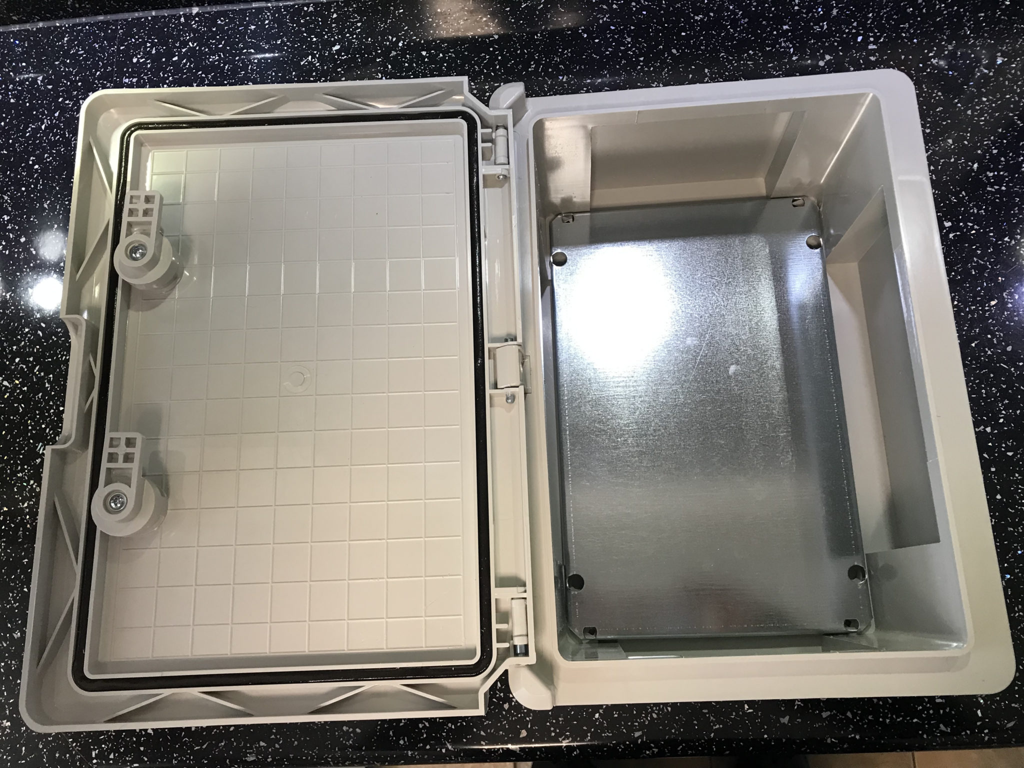
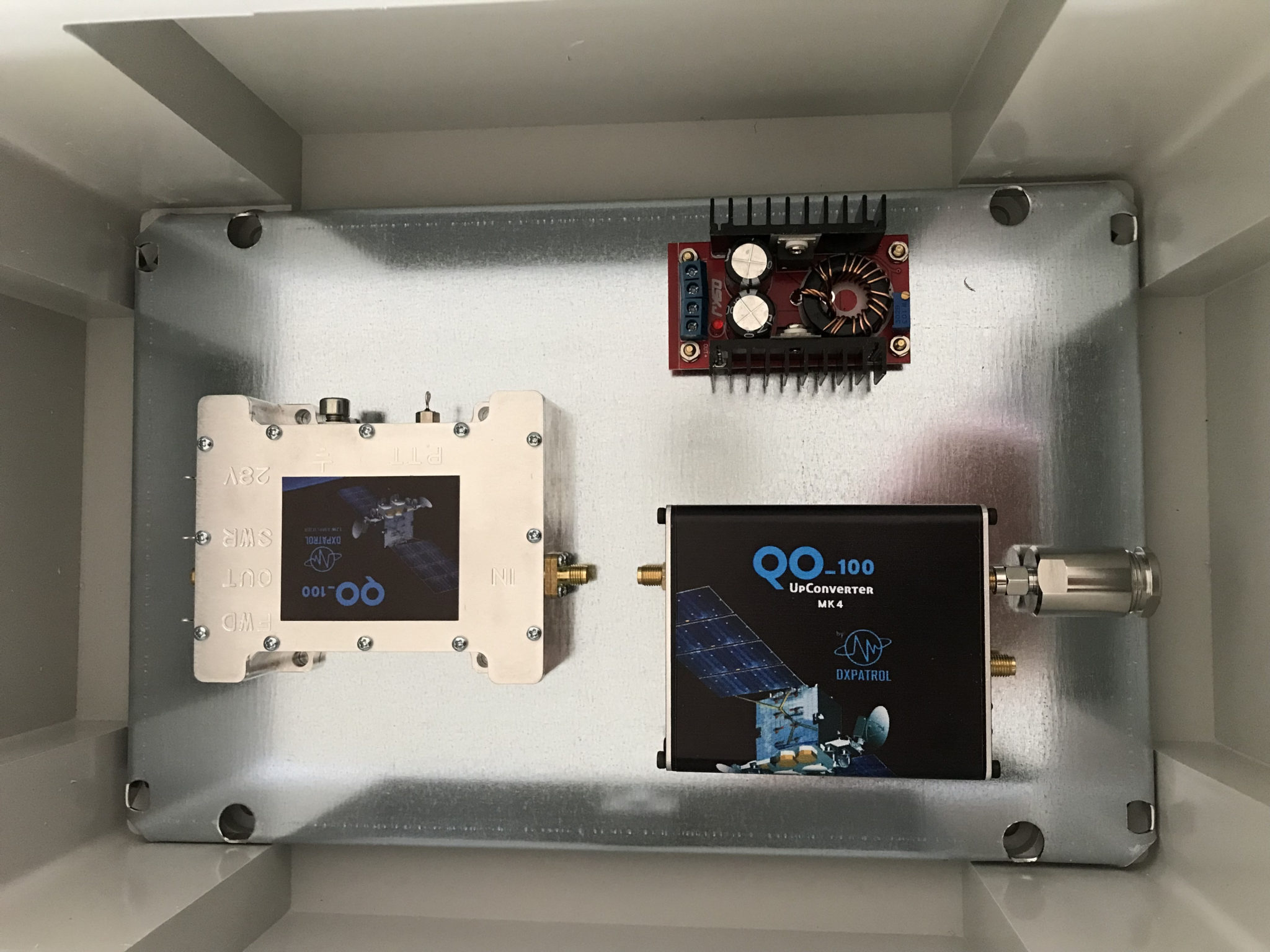
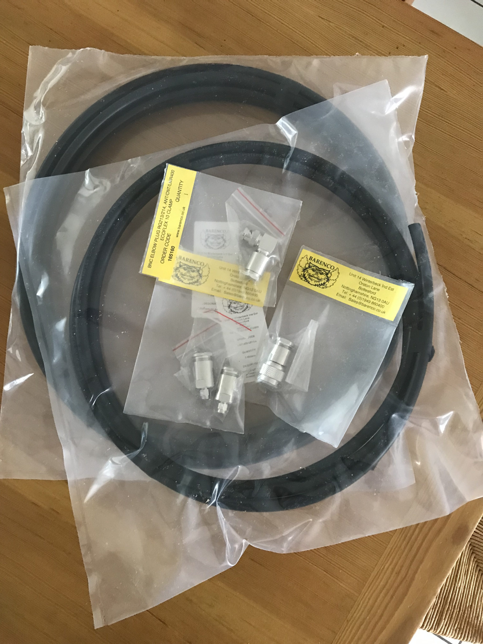
We’ve not had rain for over 6 weeks here in Eyke, Suffolk. The ground is incredibly dry and dusty. The farmers have been pulling vast quantities of water from their bore holes for weeks to keep the crops alive and we’ve been putting extra water out for the birds and animals that visit our garden daily.
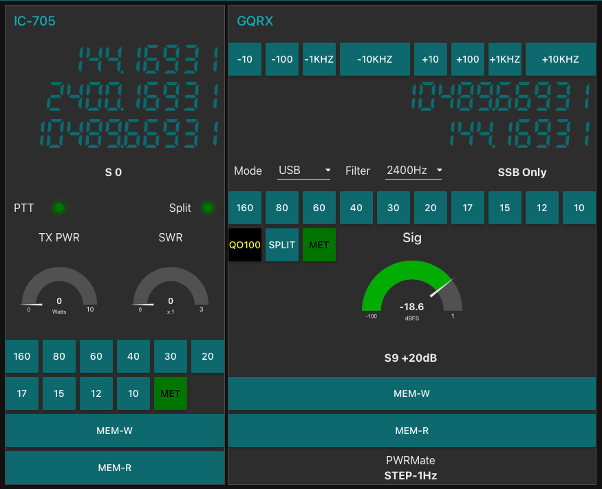
Then one night we had about 30mins of light rain, not much at all and it was consumed by the dry earth is seconds. By morning you’d never of known it had rained however, strangely the next day when I fired up my QO-100 ground station I noticed that my signal into the satellite was way down from it’s normal S9+10dB level. Checking drive into the up-converter and SWR at the IC-705 everything looked fine. I then decided to check the SWR from the 2.4Ghz amplifier output only to find that it was off the scale.
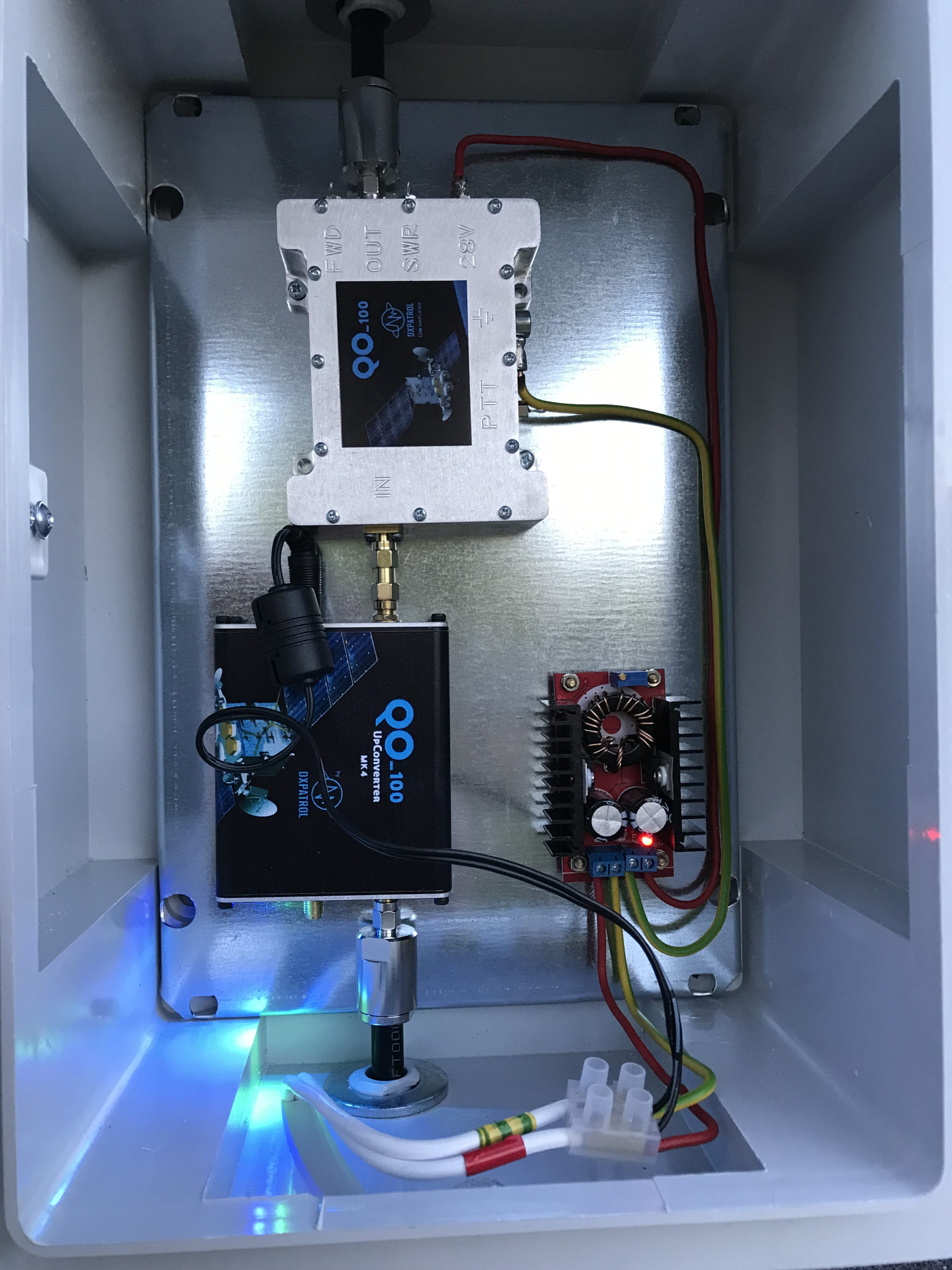
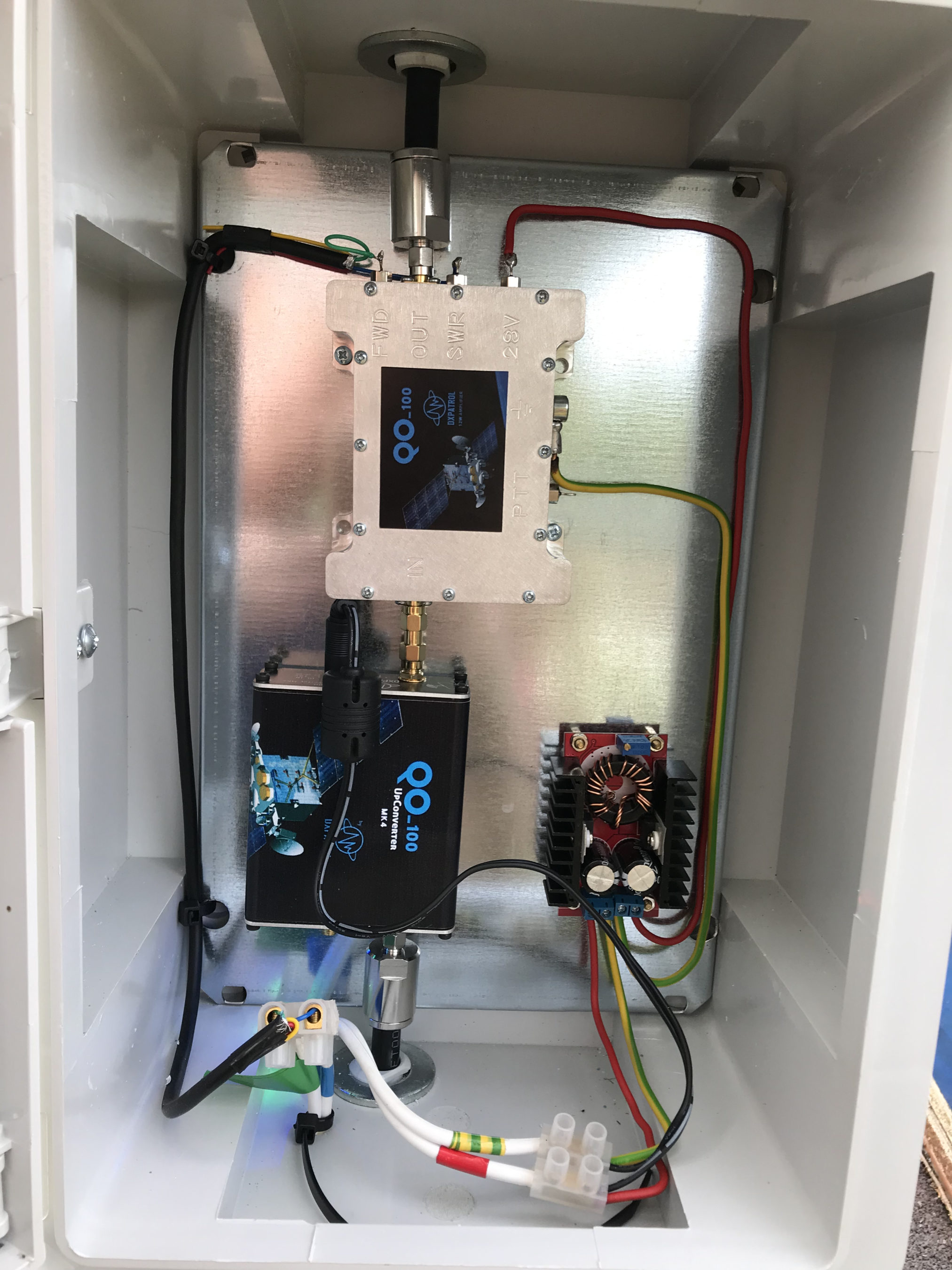
I checked inside the enclosure for water ingress but, all was bone dry as normal. I disconnected the coax cable from the output of the amplifier and the IceCone Helix uplink antenna, tested with a multimeter and found everything was fine, no short and perfect continuity.
After scratching my head for a few minutes I decided to take both the N Type and SMA connectors apart to look for water ingress. Since the inside of the enclosure was dry I wasn’t expecting to find anything.
The N connector at the Helix antenna end on the dish LNB mount was perfectly dry, no water ingress at all. The layers of self amalgamating tape I’d put over the connector had done its job perfectly. Shame I had cut the tape off to remove the plug!
Upon removing the SMA connector at the amplifier end of the coax I noticed a tiny drop of water in the bottom of the housing where the pin goes through the white plastic insulator, not a good sign.
Sure enough upon further inspection I found that the white plastic disc that is situated above the pin on the centre conductor was wet and the coax braid felt damp. I knew immediately this wasn’t good.
At first I didn’t understand how there could possibly be water in the SMA connector when the rest of the enclosure was dry. Where the coax goes into the top of the enclosure there is a water tight junction that tightly grips the coax cable and seals it, supposedly stopping water ingress.
Since there was water in the SMA connector I feared that perhaps the water had gone further and entered into the amplifier so, I decided to remove the amp from the enclosure and remove the top cover to check.
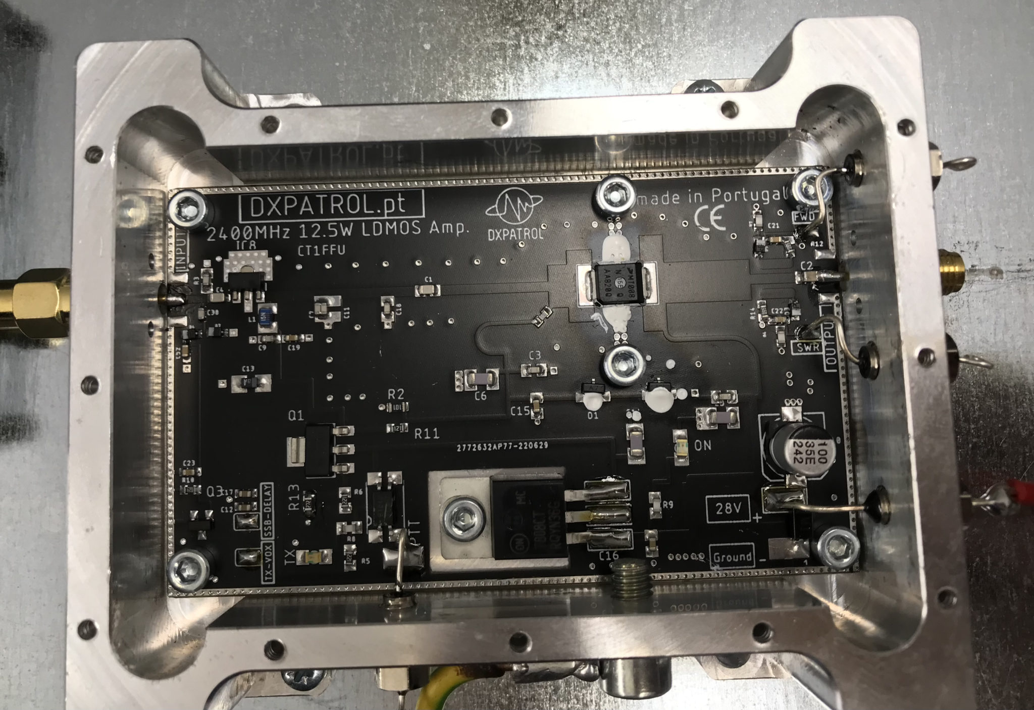
After some close inspection I found the amp to be perfectly dry and free from water ingress, a relief for sure.
Before putting it all back together I decided solder on a pair of wires to the SWR and FWD-PWR pins on the amplifier and run them down into the radio room. This would then allow me to check the SWR and power output without having to get up to the enclosure with a multimeter.
Once this was done I then set about cutting 5cm of LMR-400-UF off at the SMA connector end so that I had a fully dry piece of coax cable to refit the SMA connector to. Having to do this outside and up a ladder wasn’t the easiest but, with a little perseverance and cooperation from the breeze I managed to get the pin soldered back onto the end of the coax and the connector back together.
I reconnected the amp to the 28v feed so that I could check the SWR and power output at full rating instead of the lower 12v setting that I had been using. Checking the voltage on the SWR pin I found that it fluctuated between 0.2v and 0.44v. This wasn’t what I was expecting as the PDF manual for the amplifier states that with a 1:1 SWR you should see 1.5v on the SWR pin.
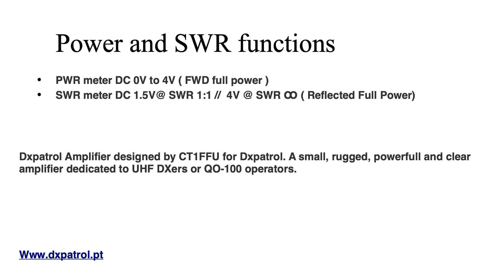
After checking all the connections and retesting and getting the same voltage reading I emailed Antonio at DXPatrol detailing my findings and asking if he could advise on the voltages I was seeing. Sure enough in no time at all he came back to me saying that the manual was incorrect and that I should see between 0.2 and 0.5v on the SWR pin for a good SWR match. Being happy that the readings I was getting were fine I emailed back thanking him for his swift reply and then moved on to check the power output safely in the knowledge that the SWR reading was within tolerances.
Checking the FWD-PWR pin I found that on SSB the voltage was fluctuating between 2v and 3v, this equates to 6w and 9w output, about right for SSB. Switching to CW mode I found the full 4v was present on the FWD-PWR pin confirming I had the full 12w output from the amp. Of course this set off “Leila” on the satellite immediately as I was a huge signal on the bird with such high power output and was a reminder to reconnect the amp to the 12v supply instead to ensure I didn’t exceed 5w output and thus keeping to a considerate level on the transponder input.
After further investigation I came to the conclusion that the water ingress could only of come from the cable inlet on the top of the enclosure, it had then run down the coax cable into the SMA connector. Somewhat annoying as the inlet is supposed to be a water tight fixing. Once I had everything back in the enclosure and securely fitted, I covered the cable inlet and coax in self amalgamating tape in the hope that this would stop any further water ingress. I also re-taped the N connector at the antenna end as well to ensure it was also protected from water ingress in the future.
I’m hoping this will be the end of my water ingress issues and that I have a dry 2.4ghz future ahead of me.
More soon …