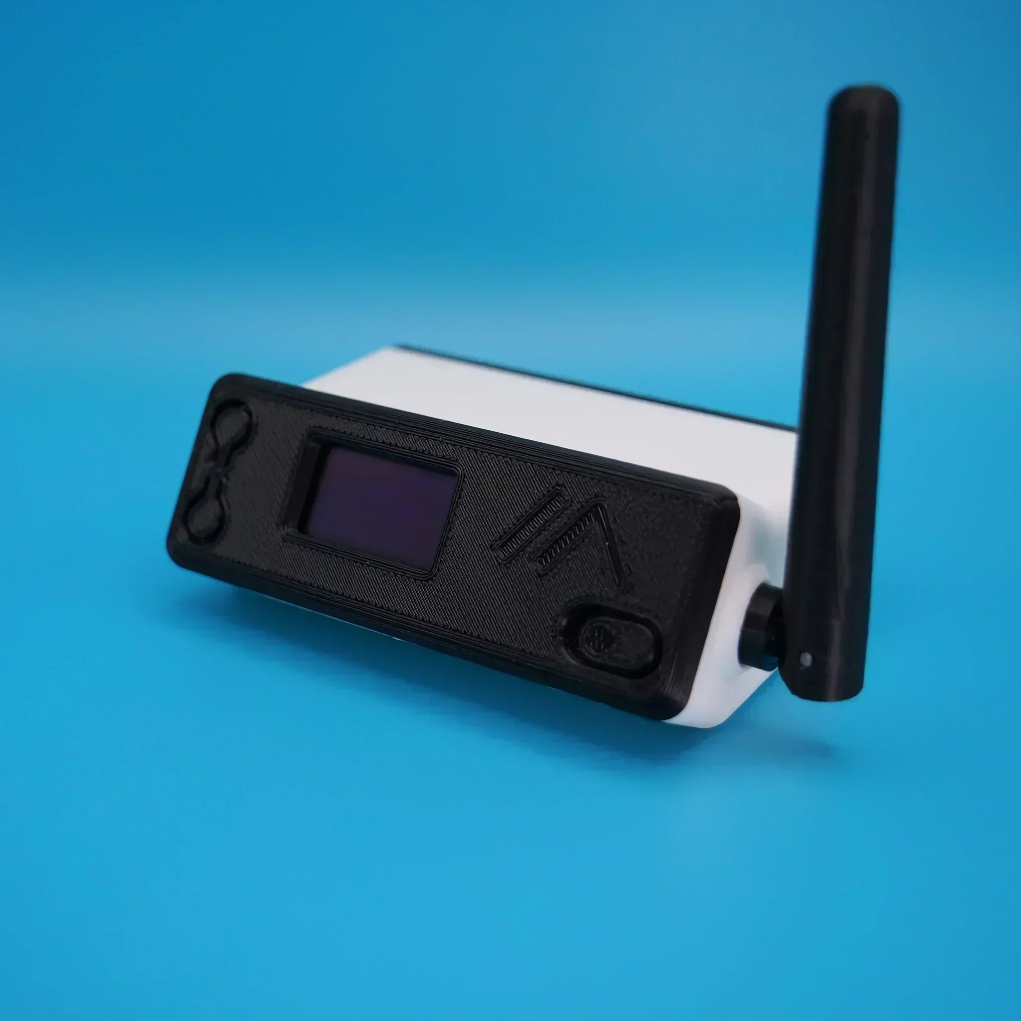
Ever since I built my RaspberryPi/SHARI AllStarLink node I’ve had to manage connecting/disconnecting to/from other nodes using the Allmon2 or Supermon web admin interfaces. These work fairly well albeit, a bit clunky and buggy. It’s impossible to use from a mobile device though and so I have to get my Macbook out each time I want to connect/disconnect nodes.
Being a Node-RED fanatic I decided that I should put something together that was more portable, mobile friendly and much easier to use. A simple user interface is all that is required and can be achieved very easily using the standard Node-RED dashboard nodes.
Initially I started investigating the Linux command-line interface for Asterisk, the VOIP system that underpins AllStarLink (ASL). I very quickly discovered that the ASL node can be very easily controlled directly from the command-line and that this would be an ideal interface to use to enable node management via a Node-RED dashboard.
In very little time at all I had an experimental control dashboard working with the ASL node and was able to connect/disconnect to/from a single node. All that was required now was to extend this so that I could connect to a number of nodes with nothing more than a push of a button.
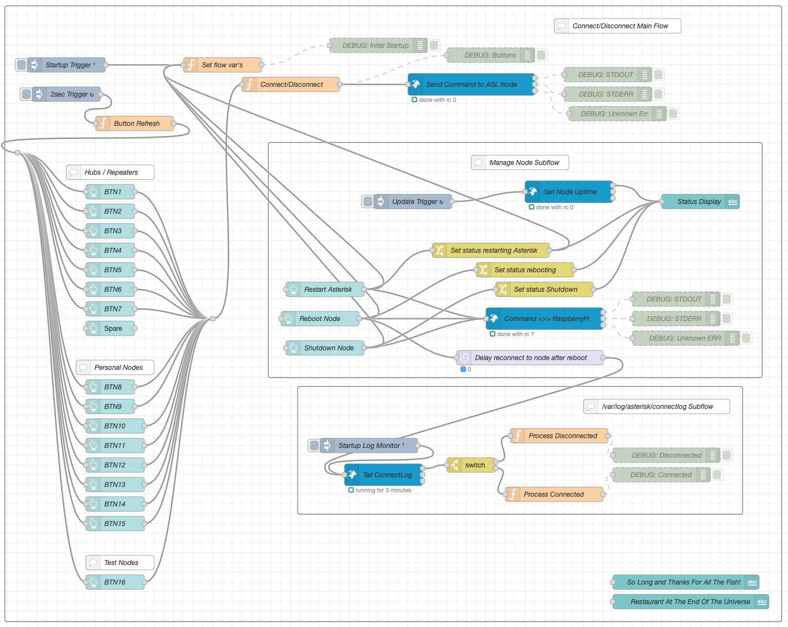
The resultant flow consists of 3 sections, Connect/Disconnect Main Flow, Manage Node Subflow and /var/log/asterisk/connectlog Subflow.
The Connect/Disconnect Main Flow handles all the input from the buttons on the dashboard and the communication to the underlying Asterisk VOIP system.
The button status is denoted by 3 colours, green (Ready to connect), orange (Transitioning to/from connect) and red (Connected). Each button is updated automatically by the button refresh function that is triggered every 2 seconds.
The Manage Node Subflow provides a simple interface to restart the Asterisk VOIP system, reboot the RaspberryPi and shutdown the RaspberryPi. The node status is automatically updated every 45 seconds and will show when the Asterisk subsystem is being restarted or the node is being rebooted or shutdown.
Finally the var/log/asterisk/connectlog Subflow monitors the Asterisk connectlog looking for connect/disconnect messages so that it can signal to update each button status.
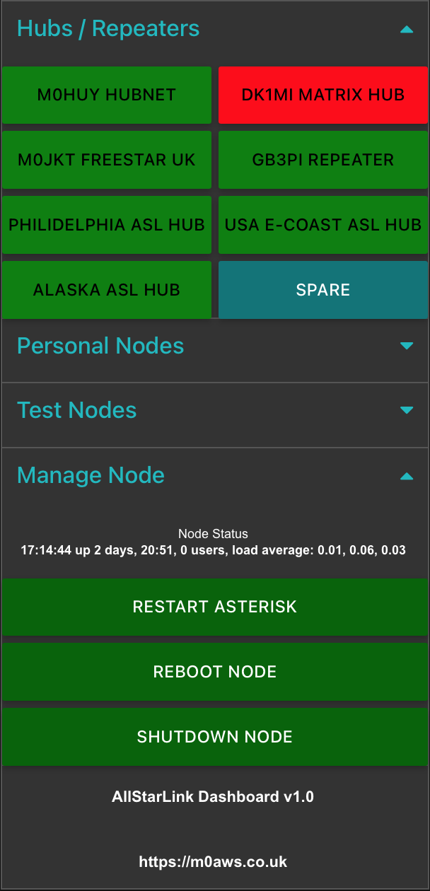
Each section of the dashboard can be collapsed/opened by touching/clicking the little blue arrows on the right of the dashboard. The dashboard works fine on Android, iOS, Windows, MacOS and Linux.
If you’re not familiar with Node-RED and haven’t yet installed it to your PC, take a look at the Node-RED Getting Started Page. The information takes you through installing Node-RED onto a multitude of devices including PC and RaspberryPi devices.
Once you have Node-RED installed all you need to do is download the AllStarLink Control Dashboard Flow and import it to your Node-RED flow editor.
Note: The link above is now for v1.2 of the flow which includes some critical bug fixes. You can read about the bug fixes in the v1.2 release article.
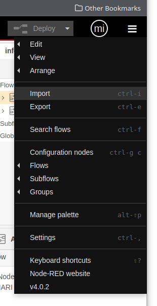
Once downloaded, select Import from the burger menu icon on the right-hand side of the flow editor as shown below and import the flow file.
Once imported you will find that some of the nodes in the flow are not available. This is because you need to add them to the flow editor palette before being able to deploy the flow.
Drop down the same menu as shown above but, this time select Manage Palette. This will open another window where you will need to select the Install tab as shown below.
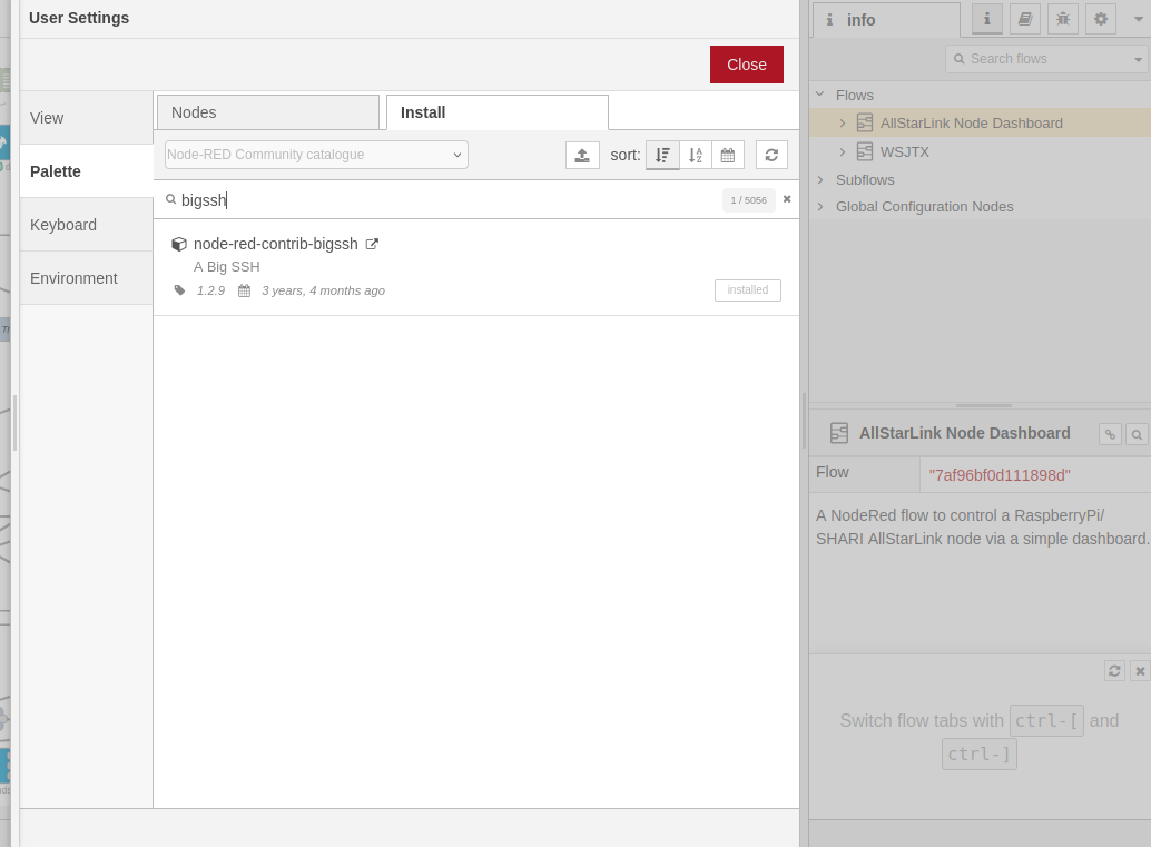
You need to install two node sets to complete the flow, node-red-contrib-bigssh and node-red-dashboard. Type in the name of each package one at a time in the search bar and then click the Install button.
Once the two packages are installed you then need to configure the credentials for logging into your RaspberryPi. This is simply done by double clicking the blue Send Command to ASL node at the top of the main flow and then clicking the Pencil button at the end of the Credentials field. This will open another window where you will need to type in the IP Address of your ASL RaspberryPi into the Host field, then enter 22 into the port field, add repeater into the Username field (repeater is the default username, if you have changed this then you will need to add the new username name in instead) and then the password associated with the repeater login into the Password field. (Normally allstarlink)
Once this is done, do the same on the other blue nodes, namely “Get Node Uptime“, “Command =>> RaspberryPi” and “Tail ConnectLog”.
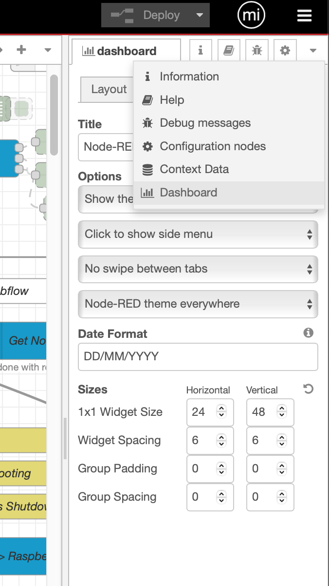
The final thing to setup is the dashboard size. Click on the downward pointing triangle at the top right of the menu bar (under the burger menu) and select dashboard. Check that the sizes are set the same as in the image below. For some reason, these settings aren’t always imported (Possible bug?) so, if your dashboard layout isn’t like shown above it will be because these settings failed to import.
You are now ready to deploy your AllStarLink Control Dashboard!
Press the red Deploy button at the top of the flow editor window.
To access the dashboard from any device, open your favourite web browser and enter the following URL: http://IP-Address-of-Node-RED-Computer:1880/ui
Finally, if you want to change the nodes that each button connects/disconnects you will need to edit the set flow var’s function at the top of the main flow. All you will need to do is replace the existing node numbers taking care not to alter the rest of the code in any way otherwise, it could stop the flow from working.
Once you’ve edited the node numbers, double click on the associated button node and change its Label to show the new node name.
Once your changes are complete, Deploy the flow again and your changes will be live.
This is version 1 of the ASL Dashboard, I already have ideas for version 2 that will also have the ability to enter a node number into a field and connect to it without the need to program it into a button.
More soon …