
Ever since I got my Class A HAM Radio licence I’ve always been fascinated by the low bands.
160m, 80m and 40m have been my favourite go to bands for chasing DX for many years and I’ve really enjoyed overcoming the challenges that come with such low frequency radio operations. Working DX on 160m I learnt a lot, having a good receiver and a quiet antenna are far more important than having a lot of power. The QRM/QRN on top band often masks the weak DX signals and so designing and building antennas that have a relatively low angle of radiation but, are super quiet on receive is a skill that all top band DXers should embrace.
It’s particularly hard to work DX on 160m in the summer months however, all those DX signals are still there, they’re just masked by the static crashes that plague top band throughout the warmer months.
Discovering the grey line was a real eye opener too. Getting up early in the morning to catch that magic moment that starts just before the sun rises to about an hour afterwards, with DX signals pouring in from VK/ZL before the D layer gets established again. Discovering that on the grey line signals from afar often arrive from a very high angle and can be heard much better on a large horizontal loop near the ground than a large vertical.
As you can tell, I’m passionate about the low bands but, now I’m back in the U.K. and have a U.K. sized garden again those days of large full wave antennas on the low bands are gone and so I must look to pastures new.
To this end I’m going to get onto the higher frequency bands, 20m and upwards. I must admit that I’ve hardly used these bands as I’ve always been so focused on the lower bands.
Currently I have delta loop for 30m up in the garden, this is a great band for us CW and digital guys, it’s a band I really enjoy and so will continue to use it whilst discovering the higher bands.
So I thought I’d start with the 20m band, it’s a band that I’ve heard is really easy to work DX on. Being much quieter than the low bands I’ll give the delta loop antennas a rest and venture into the land of vertical antennas again.
Doing some antenna modelling on EzNEC the End Fed Half Wave (EFHW) antenna has a great radiation pattern with a nice low angle of radiation and even some gain compared to a dipole.
Construction will be easy as the antenna is so small compared to the low band antennas I’ve built in the past.
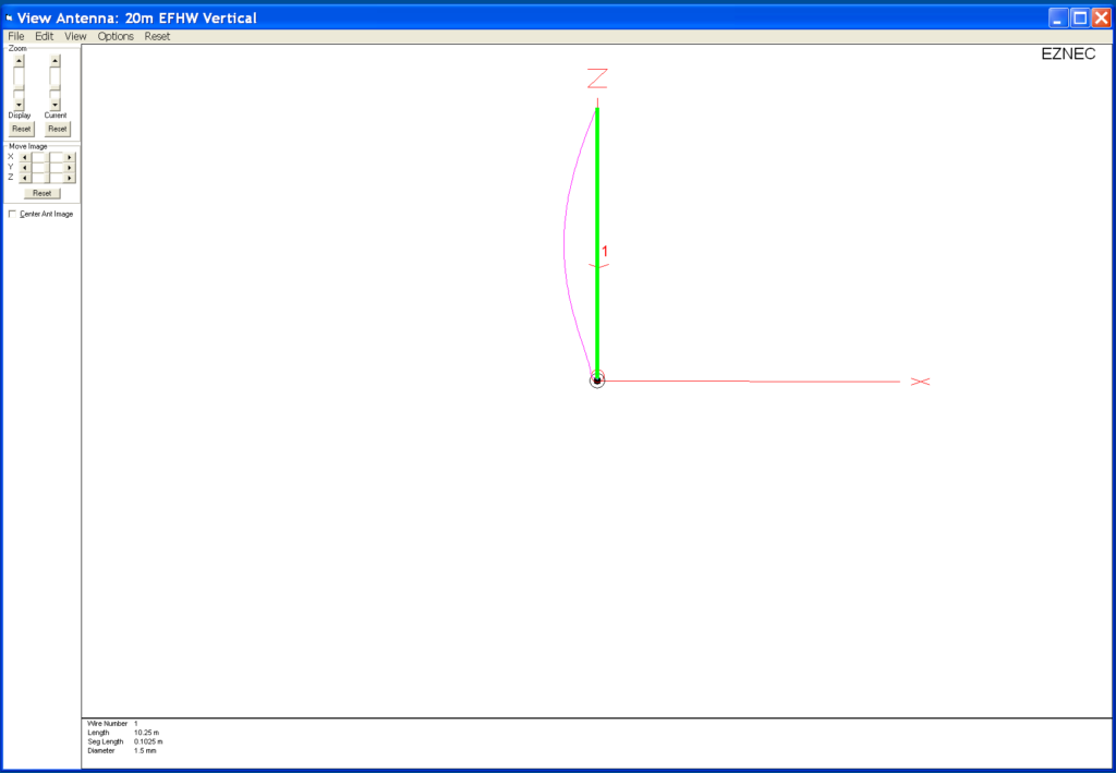
An EFHW antenna is a relatively simple affair and for 20m it’ll be somewhere around 10.25m tall depending on where on the band I resonate it.
The difficult thing about half wave or any multiple of half wave antenna is that they present a very high impedance at the feed point. Unlike a half wave dipole that is made up of two quarter wave legs that present an almost perfect match to 50 Ohm coax cable (or a 1:1 balun), the EFHW will have a much higher impedance, normally in the range of 2000 Ohms or more. Having such a high impedance also means high voltages at the ends, something to be very aware of especially if you have children or pets in the garden!
Matching to this type of antenna can be done two ways, a simple LC circuit for high impedance feed points or via a 49:1 Unun.
Since I’ve built 1:1 baluns in the past for my delta loop antennas I’ve decided to go the way of the 49:1 Unun.

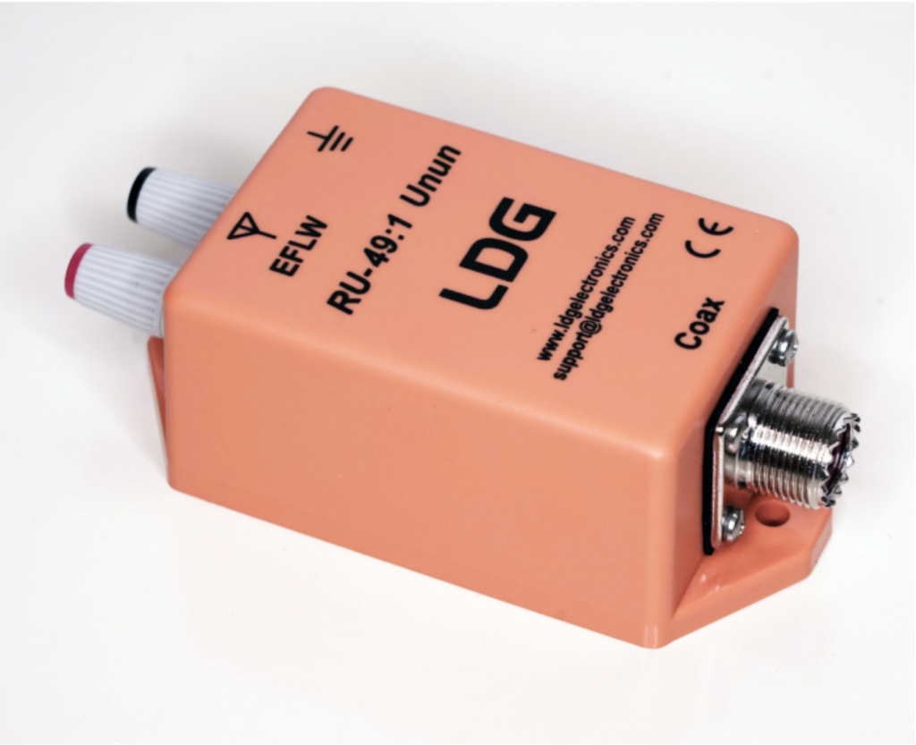
Looking online for parts to build a 49:1 Unun I stumbled across UK Antennas, they seem to have a wide selection of pre-built EFHW solutions and some very nice looking 49:1 Ununs capable of handling 400w, much more than I will ever throw at it. Contacting Ian the owner of the company via Ebay I found he has a 49:1 Unun in stock that he can ship to me next day so I decided to go ahead and order one rather than source the parts and build it myself.
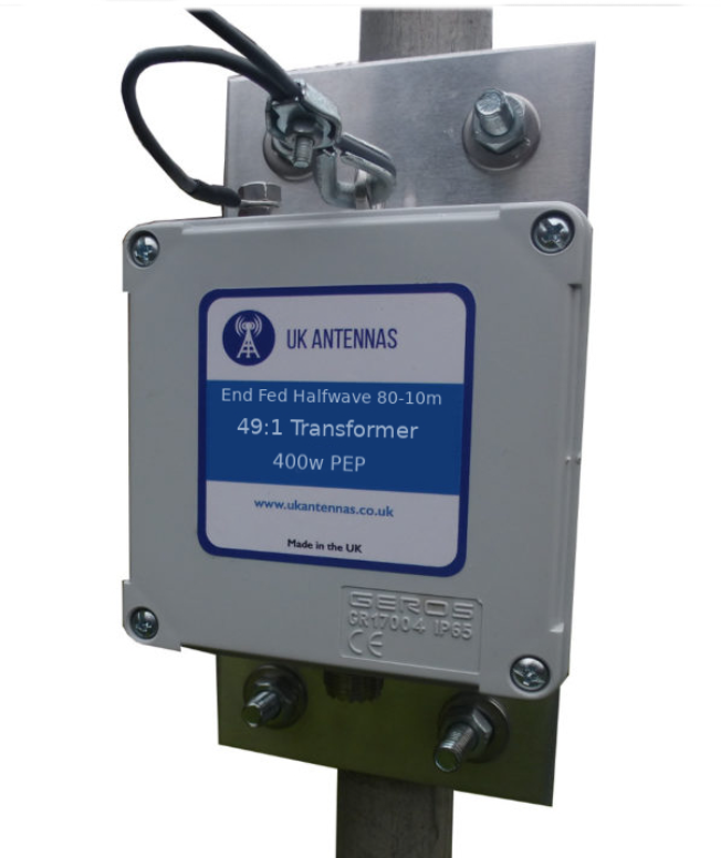
With the Unun sorted, let’s take a look at the radiation pattern for an EFHW Vertical on the 20m band.
Since I’m looking to do mainly CW and digital modes I’ll be tuning it for the lower end of the band.
Modelling this on EzNEC I’m pleasantly surprised at the radiation pattern of such a simple vertical.
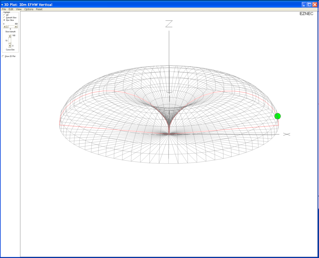
To get a radiation pattern like this on the low bands requires a very large vertical, on 160m we’re talking 80m in height!
On 20m an EFHW is only around 10.25m long, very easy to put up in most U.K. sized gardens using nothing more than an extendable fibre glass pole. The 3D Field Plot shows the lovely deep null in the centre as you’d expect and a great low angle circular radiation pattern.
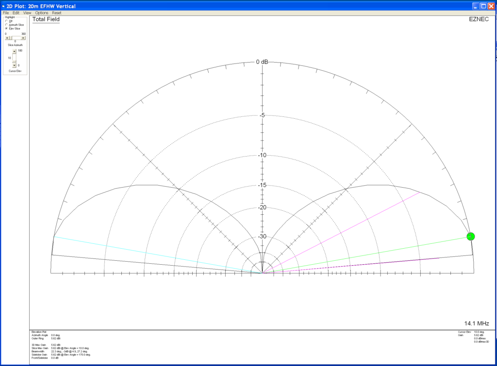
The elevation 2D field plot really shows the beauty of this antenna.
5.62dBi at 10 Deg and 5.56dBi at 5 Deg, perfect for the long haul DX chaser. The wide deep null in the centre will help attenuate the signals arriving at high angles from the EU that plague us on the East Coast of the UK.
So, it’s time to go find some wire, get cutting and get a fibre glass extendable pole mounted in the garden ready for the arrival of the 49:1 Unun.
More soon ….
UPDATES:
More info on antenna performance here.
Going QRP with the 20m EFHW Vertical and IC-705
Keeping it simple but effective – 20m EFHW Vertical


