For some time now I’ve been using an Inverted-L style antenna, albeit not a perfect L but, I have found it to perform extremely well.
When I put the antenna up I was aiming for good NVIS radiation on 80/60/40m for chatting Inter-G and local EU stations <1000 miles from my QTH.
I wasn’t expecting good performance on the higher HF bands as the total length of wire is 37m which is somewhat long for the higher frequency bands however, I’ve found performance around Europe to be very good and extremely good over the north pole to Oceania and the USA.
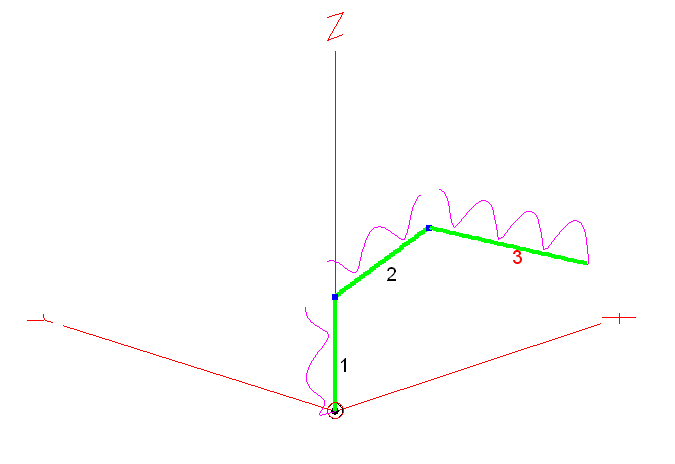
M0AWS Inverted-L style Antenna
As you can see from the antenna view above, it’s not a perfect inverted-L by any means however, its shape has actually proven to be advantageous.
Wire 1 is 9m tall, it then goes approximately 10.5m in length up to a peak of 12m above ground in the centre, this is where I have a 12m Spiderpole for support. From there the remaining 17.5m of wire slopes down to 5m above ground and is attached to the back of the house via a large insulator. Total wire length is 37m.
Wire 1 is at the bottom of a South facing garden and direction +X is north.
The antenna is tuned at the bottom of wire 1 using my CG3000 Remote Auto ATU at ground level. There are a number of random length radials hidden in the lawn and around the perimeter of the garden running mainly from South to North. I cannot run any radials to the south (-X) as this is farmland and not owned by me.
On the low bands I find it has great NVIS performance with excellent signal reports from all over the UK and out to around 1500 miles into Europe and beyond. This is exactly what I wanted from the antenna and I’ve been very pleased with it’s performance on 80/60/40m.
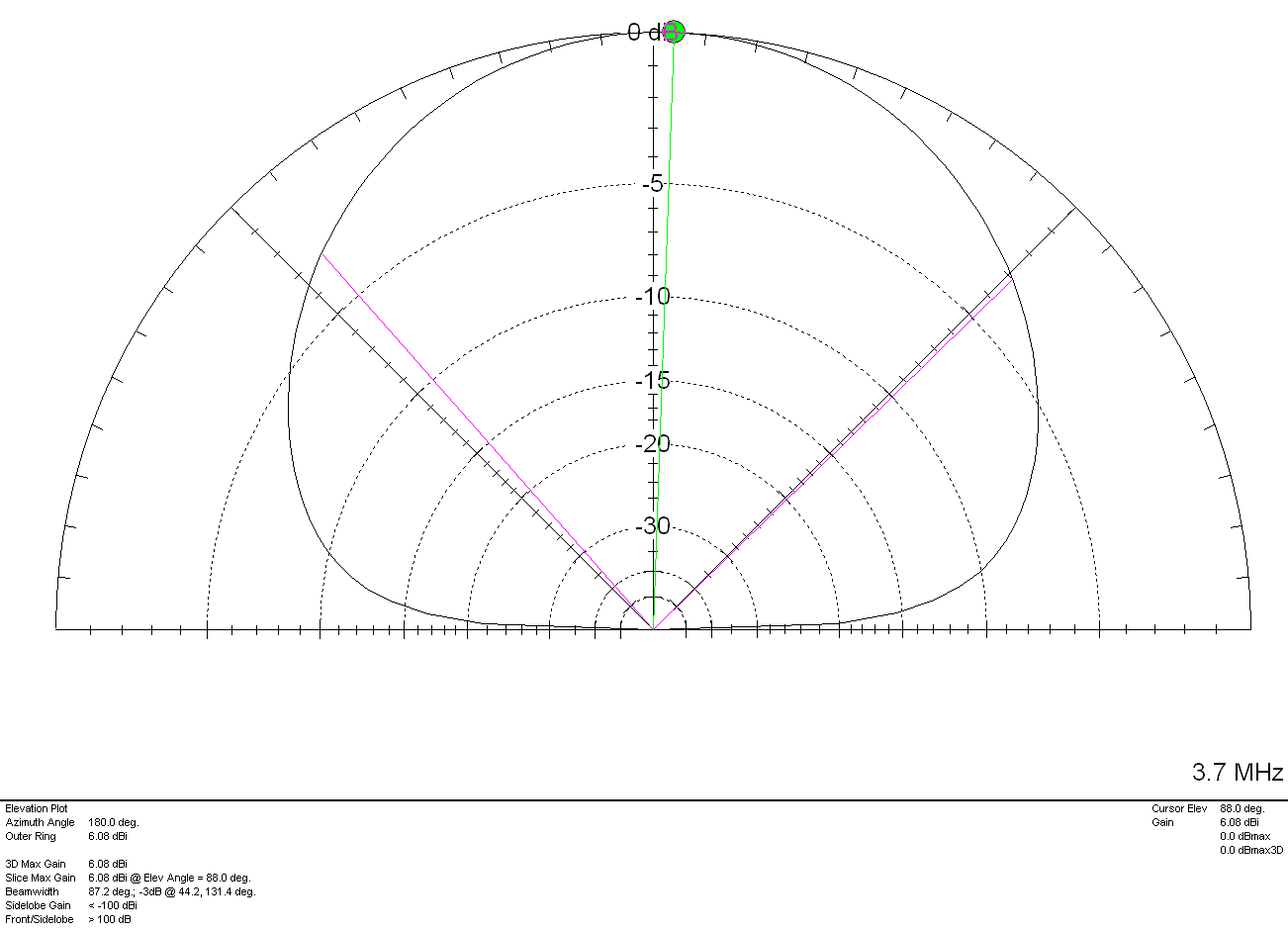
Looking at the 2D Far Field Plots on the 3 low bands the antenna has a typical NVIS high angle of radiation pattern with some gain.
M0AWS Inverted-L Style Antenna 2D Plot on the 80m Band
On the 80m band maximum radiation is straight up, as expected with a gain of 6.08dBi (3.58dBd). The gain reduces at lower angles however, it still performs well out to around 1500 miles and occasionally even further.
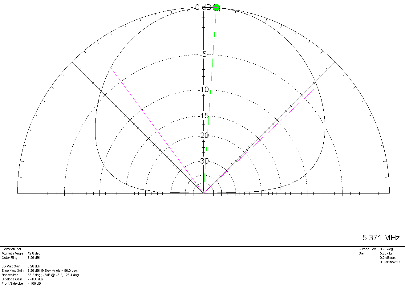
M0AWS Inverted-L Style Antenna 2D Plot on the 60m Band
Once again on the 60m band maximum radiation is pretty much straight up as expected however, I have worked in to Canada many times on 60m with excellent signal reports and so, it also has good DX capability too. With 5.26dBi (2.76dBd) gain it’s not a lossy antenna by any stretch of the imagination.
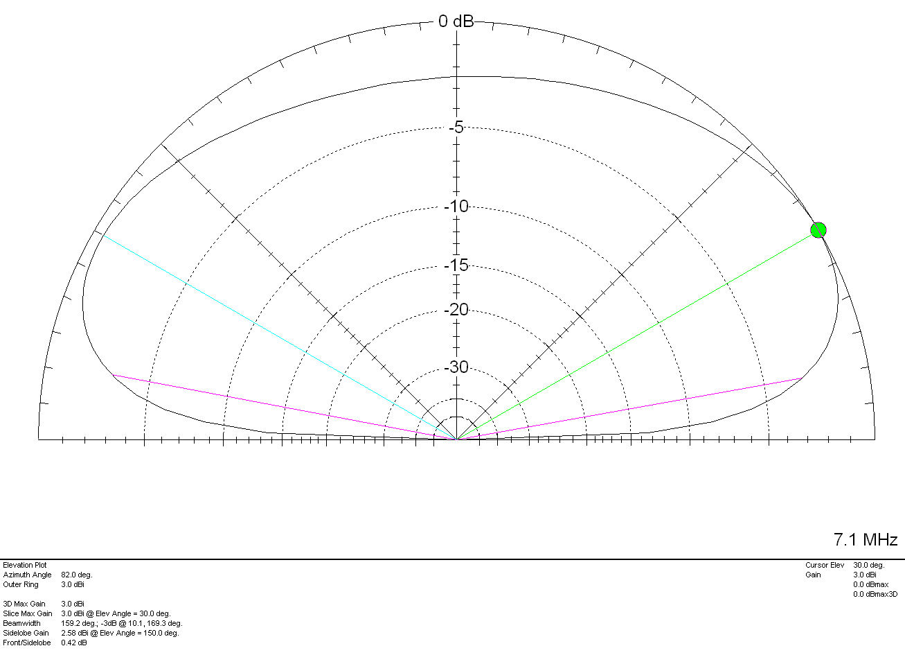
M0AWS Inverted-L Style Antenna 2D Plot on the 40m Band
On the 40m band things start to change a little with the angle of maximum radiation being at 30 degrees rather than straight up. This gives the antenna “longer legs” on the 40m band making it very easy to work longer distances. It’s still very good for Inter-G but, performance over longer distances is considerably better. With a gain of 3.0dBi (0.5dBd) it’s performance is similar to that of a dipole at a similar height above ground.
Above 7Mhz things start to change considerably. The antenna becomes directional to the North West (NW) and North East (NE) giving excellent DX results over the North Pole into North America and Australia/New Zealand. The antenna does of course also have an element of high angle radiation making it useful into Europe and North Africa on the higher bands.
M0AWS Inverted-L Style Antenna 2D Plot on the 20m Band
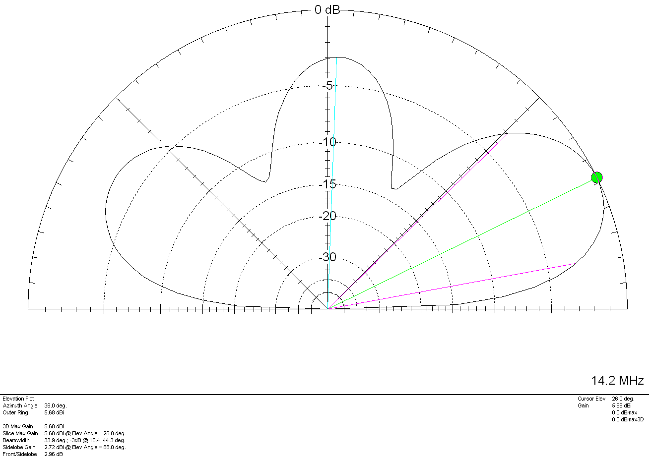
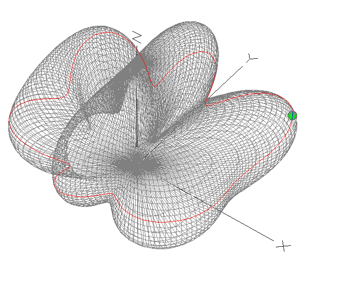
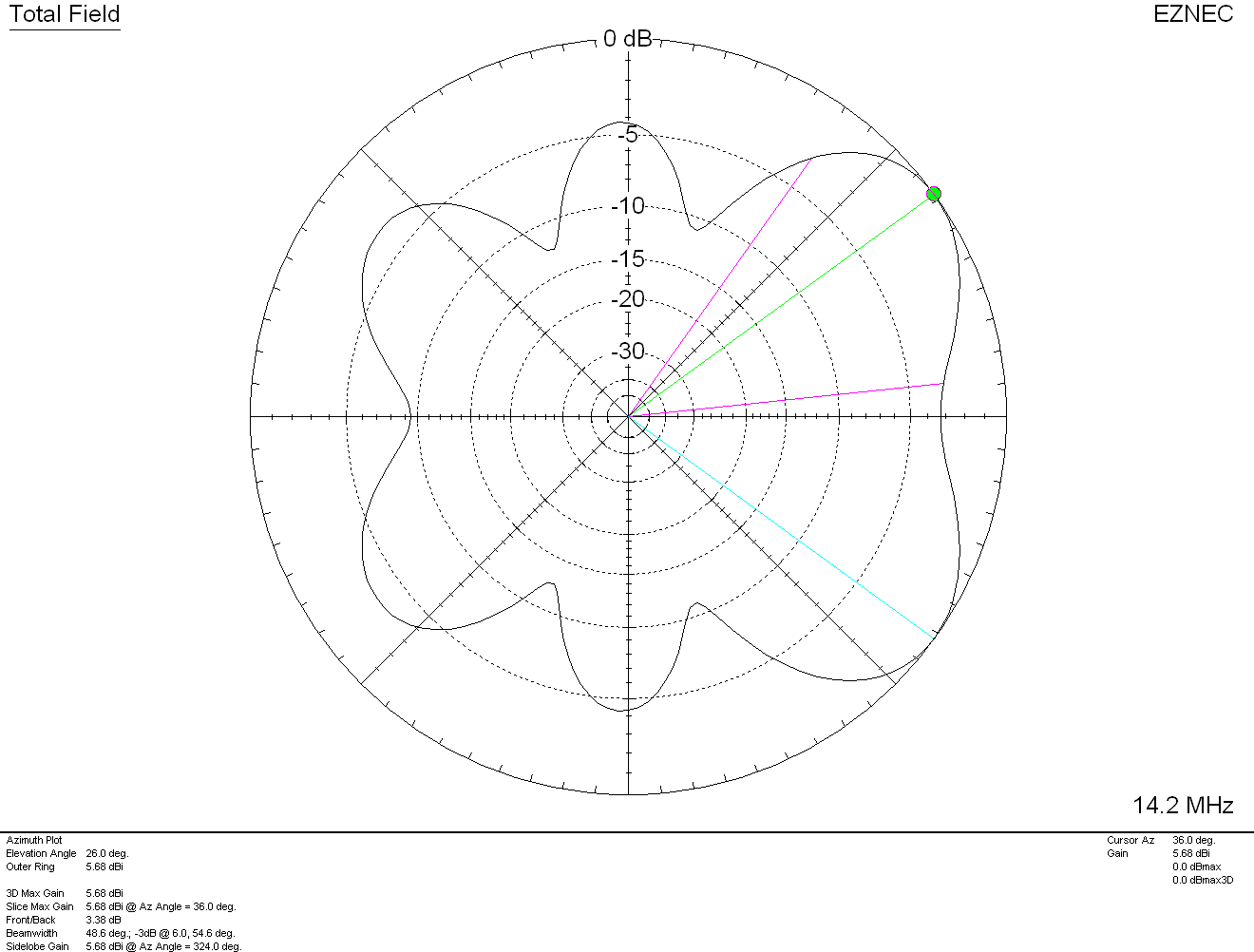
On the 20m band the maximum radiation is at 26 degrees with a gain of 5.68dBi (3.18dBd) pointing NW and NE. There is a lower gain lobe to the South West (SW) and South East (SE) giving excellent coverage through Europe and into Africa as can be seen in the 3D Far Field Plot and Azimuth Slice shown below.
M0AWS Inverted-L Style Antenna 3D Plot on the 20m BandM0AWS Inverted-L Style Antenna 2D Azimuth Slice on the 20m Band
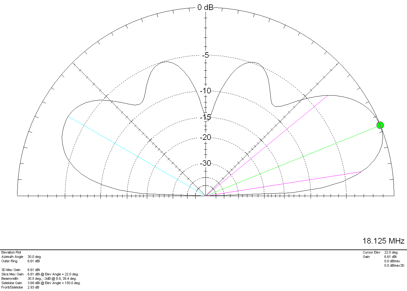
Moving up in frequency to the 17m band the 3D Plot and Azimuth Slice are similar to that on the 20m band but, with a slightly lower angle of maximum radiation and slightly more gain as can been in the 2D elevation plot shown below.
M0AWS Inverted-L Style Antenna 2D Plot on the 17m Band
With a gain of 6.61dbi (4.11dBd) at 22 degrees to the NW and NE and slightly lower gain and higher angle to the SW and SE the antenna has proven to work extremely well on the 17m band. My best DX on 17m so far has been a QSO with Eric, FK8GM in New Caledonia some 10230 miles from my QTH using just 80w of SSB.
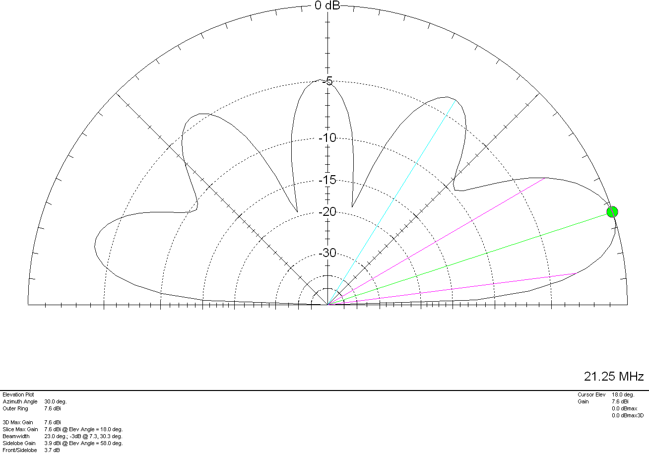
The 15m band is a similar story, 7.6dBi (5.1dBd) at just 18 degrees pointing NW and NE. This antenna works extremely well into North America and Oceana (I’ve also worked FK8GM on 15m too). Once again there are lower gain lobes to the SW and SE at a similar angle along with some high angle radiation that aids coverage into Europe. The antenna really is a great all rounder on the 15m band.
M0AWS Inverted-L Style Antenna 2D Plot on the 15m Band
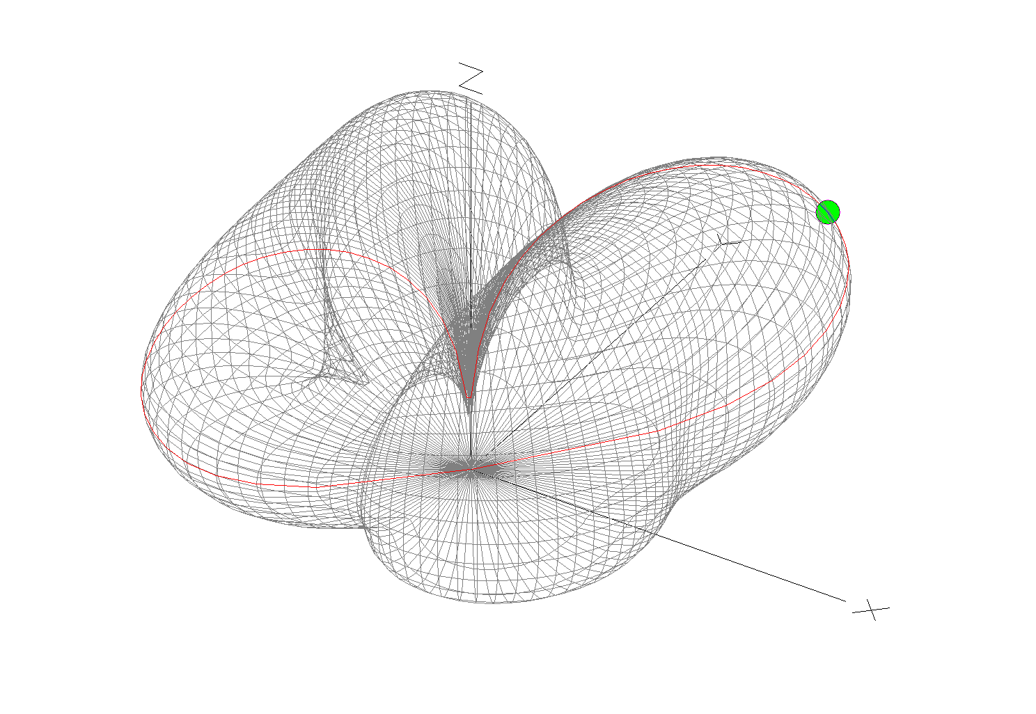
The 12m and 10m bands are a similar story, low angle, high gain lobes to the NW and NE with lower gain coverage to the SW and SE.
M0AWS Inverted-L Style Antenna 2D Plot on the 12m Band
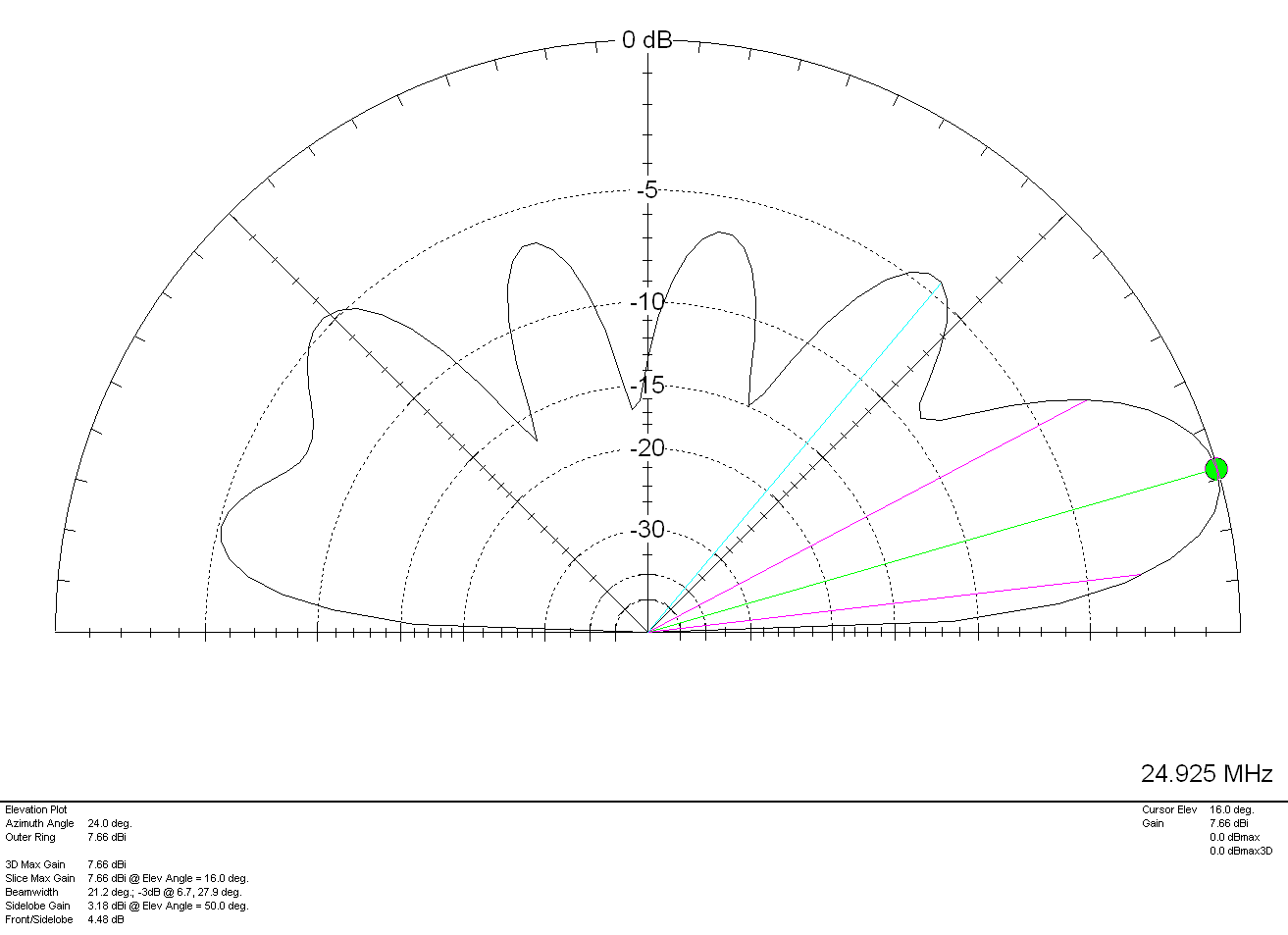
On 12m the antenna has a very respectable gain of 7.66dBi (5.16dBd) at a low 16 degrees pointing NW and NE making it a great DX antenna. Once again, higher angle lower gain lobes to the SW and SE.
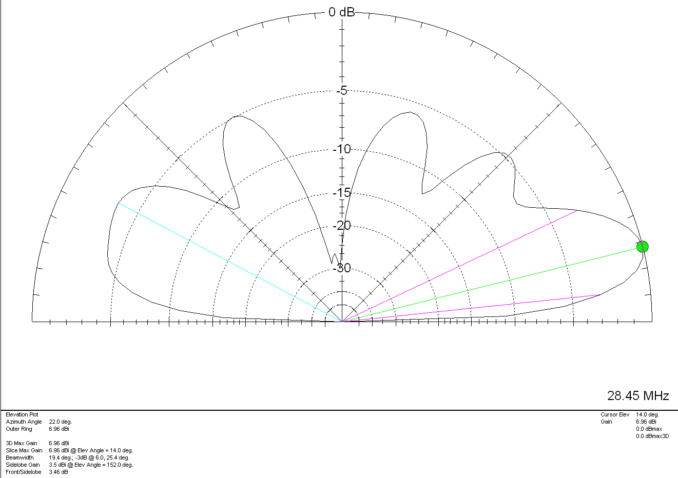
Finally on the 10m band the antenna has a gain of 6.96dBi (4.46dBd) at a very low angle of 14 degrees to the NW and NE. If DXing over the pole on the 10m band is your thing then this simple antenna will certainly help you along and maybe even put a smile on your face.
M0AWS Inverted-L Style Antenna 2D Plot on the 10m Band
For such a simple antenna that will fit easily into many typical UK gardens I have been extremely pleased with it’s performance. Whether I’m gassing on the low bands with friends from the Matrix rooms or chasing DX on the higher bands, the antenna has put a smile on my face time and time again.
On receive the antenna is surprisingly quiet, with an S3-4 background noise on the 80/60/40m bands through to less than 1 S point of noise on the higher bands. Picking out the weak DX stations really isn’t a problem.
It just goes to show that you don’t need to spend a fortune on commercial antennas to work the world on the HF bands. With as little as 80w of SSB and a piece of wire connected to a remote ATU you can have just as much fun as the big boys!
Back in January 2025 I wrote an article about a little RadioBerry Project I’d started that was based around a very old Philips 170A-15 receiver from 1946.
The idea of the project was to build a nice shortwave receiver for the radio shack based around the RadioBerry HAT on a RaspberryPi 4 housed in a vintage receiver cabinet.
The project has taken longer than I imagined due to getting side-tracked by other projects that I already had ongoing.
With the original internals removed there’s plenty of room inside for the RadioBerry, RaspberryPi 4 and the small 15w audio amplifier. The audio is delivered via a pair of Celestion speakers that I had that were originally part of an old surround sound TV system.
Power distribution is achieved very simply using a multi-plug adapter that also has USB A connections in it. The whole thing is then powered via one 240v mains cable.
The screen fits over the original opening for the glass tuning display and is held in place by two mounting screws on the rear of the LCD panel.
I purchased some new speaker grill cloth from Amazon and remade the speaker grill front with cut outs for the speakers. It looks really tidy and matches the rest of the bakelite cabinet nicely.
1946 Philips 170A-15 Shortwave Receiver RadioBerry HAT on RaspberryPi 4
To finish the project off I need to purchase 3 rotary encoders so that I can have a VFO knob and two more knobs for other things (to be determined). The Volume control is already in place with the original knob fitted to it. It will be nice to complete the 4 knob line up.
I had to make a couple of fittings top and bottom to hold the original rear panel in place but, it worked out just fine and I only had to fit an SO239 antenna connector and ethernet RJ45 port so that it can be connected to my local LAN.
Receiving radio Caroline on 648Khz
The audio quality from the little RadioBerry and 15w amp is pretty good. With the speakers hidden nicely behind the refurbished speaker grill the project looks quite tidy!
It also makes a great receiver for the HAM bands with it’s coverage of 100Khz to 30Mhz.
The DL1YCF Enhanced fork of PiHPSDR works really well on the touchscreen and provides a modern control interface to the RadioBerry HAT.
Listening to the 20m HAM Band
I’ll drop a final article once I have purchased the 3 rotary encoders to fill the 3 remaining holes in the front of the cabinet.
For the last week or so I’ve been playing with a RadioBerry HAT for my RaspberryPi computer. The RadioBerry is a cut down version of the Hermes Lite 2 with just 20mW output power and separate TX and RX antenna ports. It’s a really neat little package that sits on top of a RaspberryPi4/5 and creates a neat little HF transceiver.
RadioBerry HAT
I initially started with the RadioBerry HAT on my Pi5 but, I soon realised that the software really doesn’t work well at all on the Pi5. I’m not 100% sure as to why but, for some reason it holds one core at 100% continuously. It seems that the RadioBerry software is single threaded. The end result is that on the Pi5 you cannot use a sample rate above 9600 before the IQ stream starts to stutter.
By contrast, installing the RadioBerry software onto a Pi4 it performs perfectly upto the maximum sample rate of 384000 without any stuttering. I’ll need to spend some time going through the source code to try and determine why it doesn’t work correctly on a Pi5.
Whilst going through the source I discovered that the developer has put some code in that collects data from the running computer and sends it to the developer’s website. Some of this data is then made public via his website, http://www.pa3gsb.nl/radioberry/api/read.php
One of the things displayed on the website is the Mac address of the RaspberryPi on which the RadioBerry is running. This is a security risk and should never be done!
The most annoying thing is that this is done without authorisation. The installation doesn’t state that it’s going to collect data every time you start your RaspberryPi computer nor does it offer the ability to opt out. It also doesn’t inform the user that it’s going to pass the data on to a third party. In some cases it even collects HAM Radio Callsign and location data and displays it on a public website, a clear breach of the UK/European Data Protection Law.
Finding spyware in open source software is really poor and something most open source developers would never consider doing.
To this end I have disabled the spyware in the version of the RadioBerry software that I am using and am making it available to everyone else to use via this blog.
So, to install the RadioBerry software you just need to download the installation script and run it in a terminal on your RaspberryPi computer.
The script will download the modified source code, compile it and install it on your RaspberryPi ready for you to use.
I encourage everyone that downloads the script and the source code to take a look at it and ensure you are happy with it. It’s important to know what you are running on your computer and what it does.
You can find the spyware code in the register.c file (It’s all commented out with “//” marks). The function now doesn’t pass any data at all to the public website.
I hope some of my readers who are experimenting with the RadioBerry transceiver find this useful.
I will soon be publishing an article on an enhanced version of PiHPSDR from DL1YCF to use with the the RadioBerry to complete the project.
Important Update:
There is an issue with the RadioBerry code that renders it useless if you use a kernel later than the version shown below:
Updating the O/S Kernel to any version later than the version shown above will stop the RadioBerry software from working. Recompiling of the code also fails due to the Kernel update and at the time of writing this cannot be fixed without a code rewrite by the original developer.
I also recommend that once you have built a working RadioBerry on a RaspberryPi 4 you should disable the automatic updates of the O/S to stop the system from failing in the future.
You can disable the automatic updates by entering the following commands into a terminal:
I’ve been doing some antenna modelling and comparisons for John, W2VP comparing some phased and parasitic arrays. One of the phased arrays I modelled was an End-Fed-Half-Wave (EFHW) phased vertical array for the 40m band. It’s got such a nice radiation pattern that I thought I’d add it to my antenna pages here on the website for others to read too.
M0AWS 40m Band EFHW Phased Vertical Array Antenna View
The EFHW Vertical Phased Array is as simple as two vertical half wave wires both of which are fed via their own 49:1 Unun. Wire 1 (radiator) is exactly 20m tall and wire 2 (reflector) is 21m tall. The space between them is exactly 10.5m.
This simple antenna arrangement gives a surprisingly good radiation pattern with a reasonable forward gain and front-to-back (FB) ratio.
M0AWS 40m Band EFHW Phased Vertical Array 3D Far Field Plot
The antenna has quite a wide beam width which is to be expected from a pair of phased verticals. The nice thing about this array is that it has very little in the way of high angle radiation. This makes this antenna ideal for long distance communications. This isn’t an antenna for local chatter!
M0AWS 40m Band EFHW Phased Vertical Array 2D Far Field Plot
The 2D Far Field Plot shows that the antenna has a forward gain of 3.16dBi at 19 degrees. This is some 8 degrees lower than a typical 1/4 wave vertical phased array. The array also has a very respectable front-to-back (FB) ratio of 20.53dB.
Both elements in the array will need to be fed via individual 49:1 Ununs with the reflector requiring a feed phase angle of 100 degrees. A 100 degree phase angle gives better performance than the typical 90 degree phase angle that is typically used for 1/4 wave arrays.
For such a simple design this antenna should give great DX results as long as you have the necessary supports for the two vertical wires and the space for the guy lines. If only my garden was much bigger and I had some large trees to hand!
Summary:
Radiator (Element 1): 20m Reflector (Element 2): 21m Reflector Feed Phase Angle: 100 Deg Wire Dia: 4mm Feed Type: 49:1 Unun on each vertical element and a phasing harness Impedance: 50 Ohm SWR: <1.5:1 across whole band
Following on from the article I wrote about the performance of my multi band vertical antenna I’ve now put together a table showing it’s performance on each band as experienced over a period of 18 months.
It’s interesting to note the antenna wavelength measurements on each band as 13m (43FT) seems to be an almost perfect length for a simple multi band vertical HF antenna with excellent DX capabilities.
M0AWS 13m (43FT) Multiband Vertical HF Antenna Info (Click to Enlarge)
Looking at the information you can see that performance on the 160m band is poor. This is to be expected as the antenna is far too short for a band with such a long wavelength. I knew this would be the case from the outset and never planned to use this antenna on the 160m band. I’ve included the data here just for completeness. If you’re looking for a reasonable 160m band antenna that can fit into an average UK garden then take a look at my Inverted-L antenna article.
Performance on the 80m band is surprisingly good considering the antenna is only 1/6th of a wavelength long. With contacts into Indonesia achieved using relatively low power levels this antenna surprised me with its performance on the 80m band. A 1/4 wavelength antenna would of course perform better but, like all multi band vertical antennas for the HF bands there is always a compromise.
On the 60m band the antenna is pretty much a 1/4 wave vertical, it works great on this band and I’ve had a lot of fun chasing DX in the winter months. With the longest contact being into Brazil at 6144 miles this antenna performs extremely well for such a simple design.
On the 40m band performance is better still. With the antenna being just over a 1/4 wavelength long the point of max current is above ground level making this a very good DX antenna. With multiple contacts into Australia at distances over 10,000 miles this antenna is the ideal 40m band DX chaser for small gardens.
Moving up onto the 30m band this antenna now begins to really shine. Being a half wave long on 30m the point of max current is half way up the wire lowering the angle of radiation considerably. This results in excellent global coverage with contacts into Australia being a breeze. With the longest distance achieved being 11,776 miles into New Zealand this really is the goto antenna for fans of the 30m band with small gardens. This antenna easily out performs my 30m band Delta Loop design whilst giving better global coverage.
On the 20m band this antenna performs very well indeed. Considering it’s 3/5th of a wavelength long which is a strange length to have, it’s no slouch. Global coverage is excellent and working into Australia is relatively easy. I’ve yet to work into New Zealand on the 20m band using this antenna but, that’s mainly due to me not being on air at the right times. Best distance worked so far on this band is 10,656 miles.
On the 17m band the antenna is 3/4 wavelength long. This is a very useful length and easy to tune as it presents pretty much 50 ohm impedance at the feed point. Performance is simply stunning on 17m, if you can hear the DX you can work them. I am amazed at how well this antenna works on this band. It seems to have a low angle of max radiation making it excellent for chasing DX stations. Giving me my first contacts into Alaska and New Zealand this is my goto antenna for the 17m band.
On the 15m band this antenna is 7/8th of a wavelength long. Performance doesn’t feel as good as it does on 17m but, with the longest distance achieved being 8023 miles there’s really no reason to doubt it. With only 87 contacts being made on this band due to the fact that I always get trapped chasing DX on the 17m band and never make it any further up the bands, I’m sure this antenna will perform extremely well long term on 21Mhz. I just need to make more effort to get on this band.
The 12m band is one of the bands I didn’t expect this antenna to perform well on. Being 1 and 1/8th wavelengths long it’s not a length that you would normally consider using for an antenna however, performance is excellent. This is most likely due to the point of max current being a fair way up the wire resulting in a low angle of maximum radiation. DXing is great fun with this antenna on the 12m band and it’s surprised me time and time again at how easily I’ve been able to work DX stations. With the best distance worked so far being into the Falkland Islands at 7973 miles, this antenna has huge potential on this band. Like the 15m band, I need to make an effort to spend more time on the 12m band and see how far I can push this antenna.
Finally we reach the dizzy heights of 28Mhz on the 10m band where the antenna is 1 and 1/4 wavelengths long. Again this is a useful length as it presents almost 50 ohm impedance at the feed point. DX performance on the 10m band is good. It’s probably very good however, like the 15m and 12m bands, I rarely make it up onto the 10m band and so I’ve not really given the antenna the time to prove itself at 28Mhz. My best distance worked so far on this band is 4872 Miles into the USA but, I’m sure I could easily do better if I committed more time to it.
I’ve pretty much covered all the good points of this simple multi band antenna so, now let’s look at the not so good points.
If you’re in the UK and are looking to work other UK stations then this antenna isn’t for you. Like all vertical antennas there isn’t much in the way of NVIS radiation and so you’ll find UK stations just won’t hear you. You’ll also often find you won’t hear UK stations at all due to the null at the top of the antenna that attenuates signals arriving from high/very high angles. For me this is fine as I wanted an antenna that was focused on DXing as much as possible.
From 10Mhz upwards the antenna also isn’t that good for working stations in nearby Europe. Most of the time you will only hear European stations that are more than 1000 – 1500 miles away, anything closer just doesn’t appear in the receiver. On the 15m and 12m bands often you will never hear European stations at all, only DX stations. This does of course reduce the QRM from UK/EU stations considerably making it easier to work those weak/QRP DX stations.
So as you can see, 13m (43FT) of vertical wire is probably one of the best lengths you can possibly use for a multi band vertical HF antenna especially if like me, you have a small garden to squeeze your antennas into. I don’t like to say it but, this could be the magical length we’re all looking for when making a multi band HF vertical antenna.
Tuning of the 13m (43FT) vertical antenna is achieved using my CG3000 remote auto ATU. I initially started off using my home-brew Pi-Network ATU but, changed over to the CG3000 so that in the winter months I don’t have to run out into the rain and wind to change bands. It’s important to note that the ATU must be at the base of the wire and not in the radio shack. It’s also important to note that I have 4 x 20m long radials connected to the CG3000 along with an earth spike at the base of the wire. This combination of ground and tuner works incredibly well with the ATU tuning on each band with ease in less than 3 seconds. I’ve also not had any issues with the CG3000 attempting to retune whilst in the middle of a QSO, once it’s initially tuned it doesn’t retune again until I either change band or make a large change in frequency.
The achieved SWR on all bands is <1.5:1 except for 160m where it is 1.8:1.
Since I put together my Inverted-L antenna and Pi-Network ATU I’ve been having a lot of fun on the low bands.
Getting back onto 160m has been most enjoyable and I’ve now had over 100 ‘Top Band’ contacts with distances covered as far as 3453 Miles into Sosnovoborsk Asiatic Russia.
I must admit I am amazed at the distances achieved on the 160m band as the antenna isn’t very high above ground level when compared to a single wave length on 160m.
M0AWS Inverted-L Antenna View
The Inverted-L antenna at the M0AWS QTH was designed purely around the size of the back garden. Using a couple of 10m Spiderpoles the vertical section of the antenna is 10m tall and the horizontal section is 28m long. Naturally the antenna resonates around 2.53Mhz but, can be tuned to resonate anywhere on any band using the Pi-Network ATU I built that is situated at the base of the vertical section of the antenna.
Looking at the far field plots for the antenna on each band we see that as we move higher in frequency the radiation pattern becomes more complex and the radiation angle gets lower, exactly what we would expect from such an antenna. The antenna runs pretty much North/South in the garden ( X axis on the diagram above) and so we would expect the antenna to radiate East/West (Y axis on the diagram above) however, this isn’t always the case.
M0AWS Inverted-L Antenna 160m 3D Far Field PlotM0AWS Inverted-L Antenna 160m 2D Far Field Plot
(Click Far Field Plots for full screen view)
On 160m the antenna favours the South (-X Axis) and presents some usable high angle gain although, from using the antenna you would never know this to be the case as it seems to have pretty good all round coverage. With the best distance of 3453 Miles being covered to the East into Asiatic Russia the antenna performs well even though the far field plot is slightly biased to the South.
M0AWS Inverted-L Antenna 80m 3D Far Field PlotM0AWS Inverted-L Antenna 80m 2D Far Field Plot
On the 80m band the Inverted-L antenna becomes a cloud warmer and exhibits very high angle radiation. On 80m the antenna is ideal for NVIS Inter-G propagation and is great for rag chewing with other UK/Near EU stations.
M0AWS Inverted-L Antenna 60m 3D Far Field PlotM0AWS Inverted-L Antenna 60m 2D Far Field Plot
Looking at the far field plots for the 60m band once again the antenna provides lots of high angle gain however, there is also some very useable lower angle gain that has proven to be excellent for working long hauls into North America and east into Central Asia. On the 60m band during the day the antenna is excellent for Inter-G chatting, using just 20w-40w I can very easily chat with other UK HAMs even when the band is noisy.
M0AWS Inverted-L Antenna 40m 3D Far Field PlotM0AWS Inverted-L Antenna 40m 2D Far Field Plot
Moving on up to the 40m band we find the far field plot starts to get a little more complex. Looking at the 3D plot you’d think that the antenna favoured the South (-X Axis) however, in reality it favours the NorthWest with both some high and low angle gain. This antenna has proven to be excellent for DXing into North America on 40m but, has also been great for DXing into South America getting great signal reports from stations in Panama at a distance of 5415 Miles. During the day NVIS propagation is excellent and I find I can chat with other UK and near EU stations with ease using just 25w.
M0AWS Inverted-L Antenna 60m/40m Global Coverage
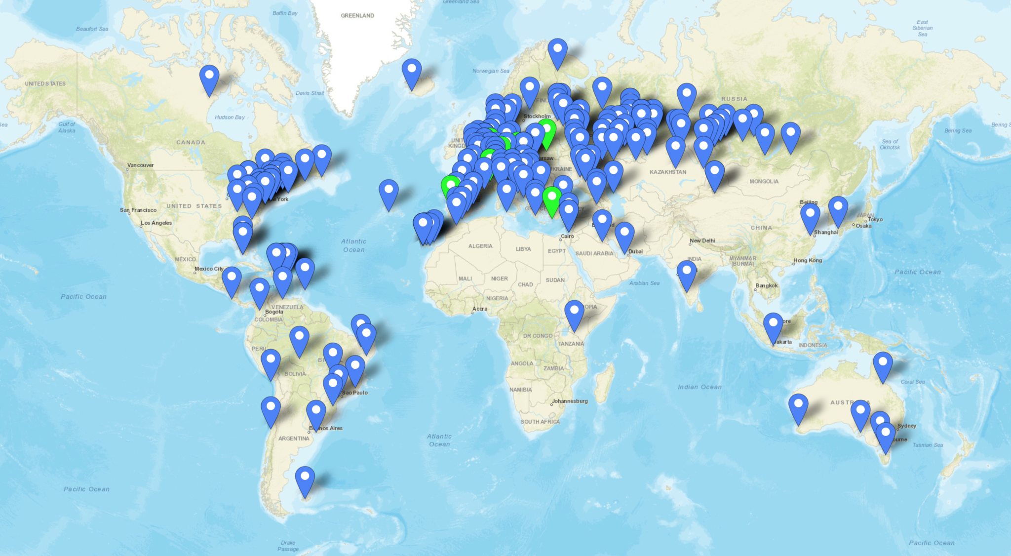
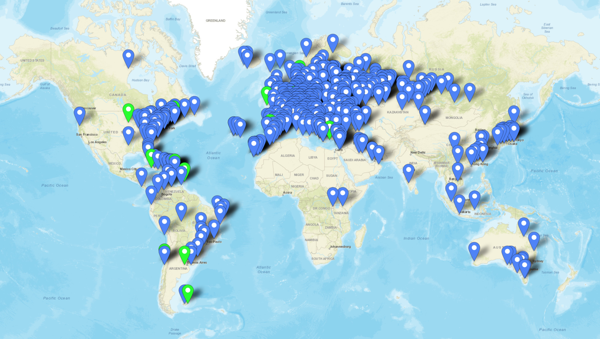
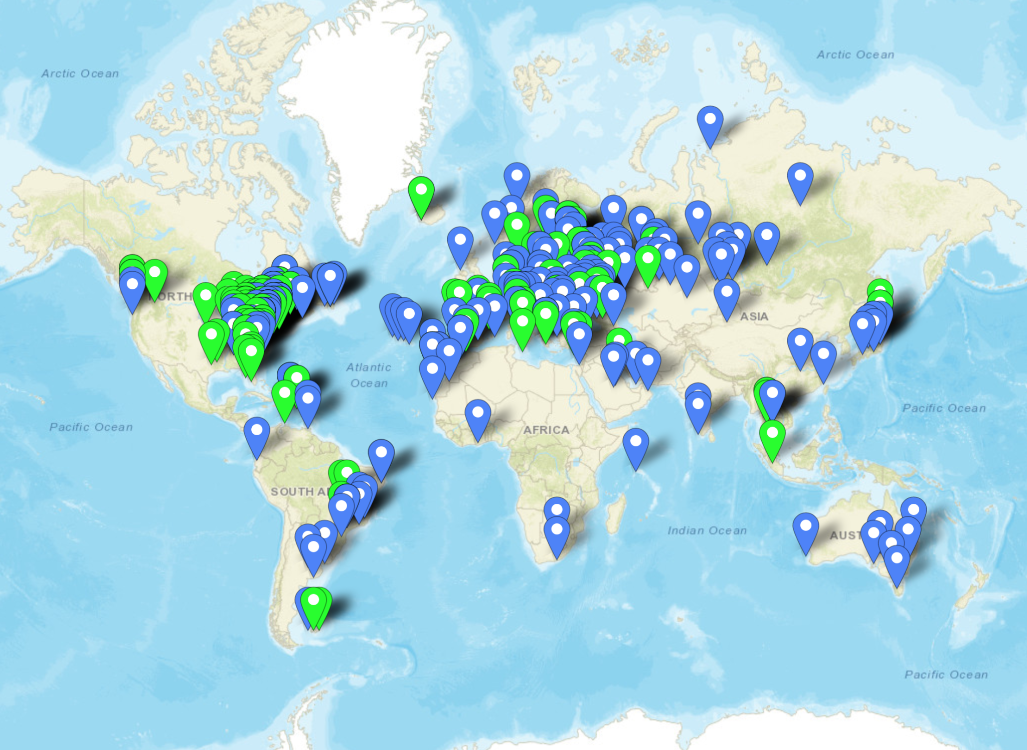
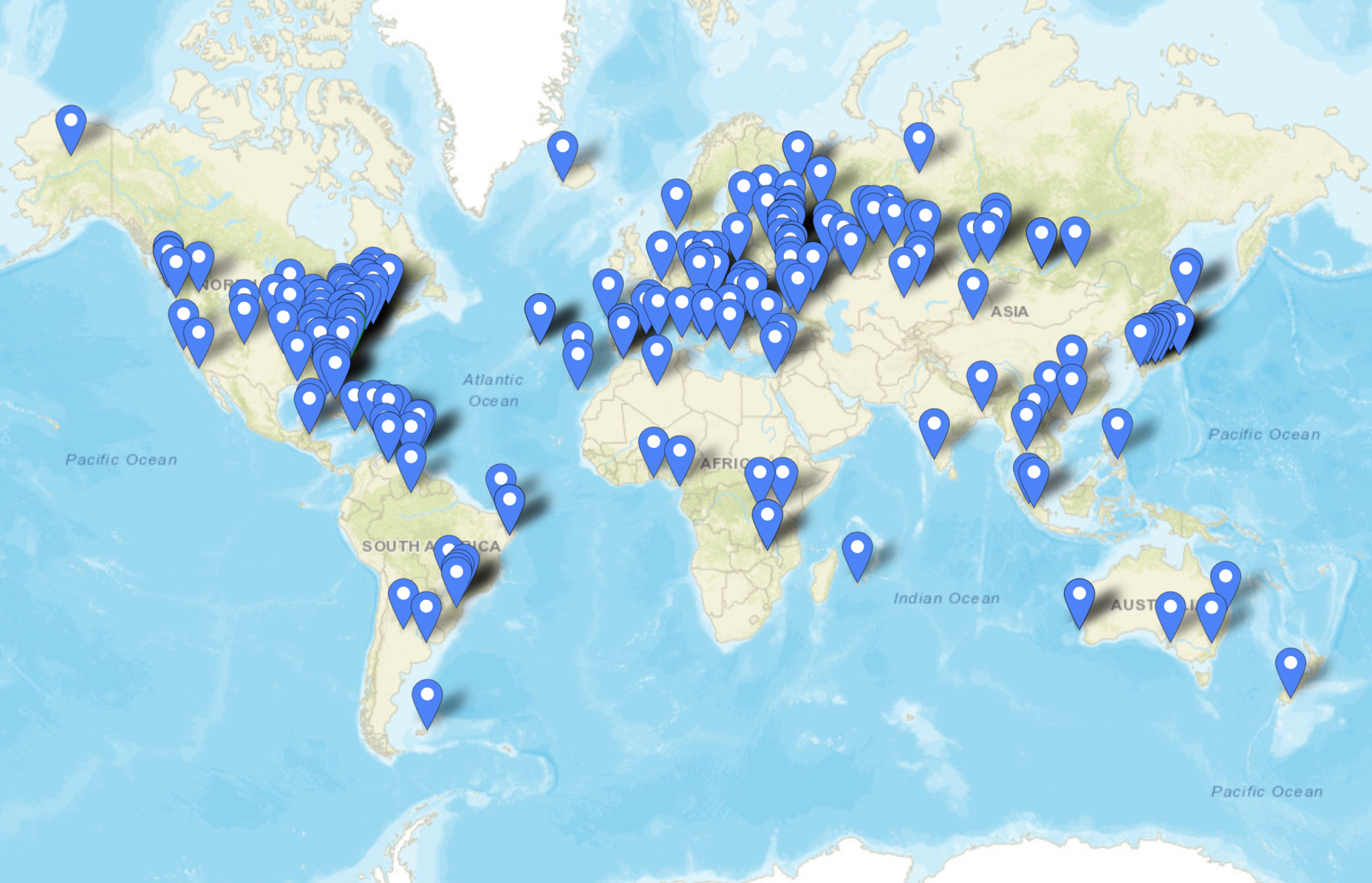
Above is a screen shot from PSKReporter showing stations that have heard me on the 40m and 60m bands. As you can see, global coverage is excellent with stations as far as Australia and New Zealand hearing me on the 40m band and stations on the West Coast USA hearing me on the 60m band. I was also pleased to see I was heard in Africa on both bands, a region of the world I would like to get more contacts from.
M0AWS Inverted-L Antenna 30m 3D Far Field PlotM0AWS Inverted-L Antenna 30m 2D Far Field Plot
On the 30m band the Inverted-L antenna starts to exhibit two lobes with gain to the NorthEast and NorthWest. This makes the antenna ideal for working into the USA and Australia/New Zealand over the North Pole. Working US stations is a breeze with relatively low power and I almost got a contact with New Zealand during the evening greyline but, unfortunately the DX station dropped out before I managed to get my signal report back to him. As time goes on I’m sure the antenna will more than prove itself on the 30m band.
So far I’ve not ventured above the 30m band with the Inverted-L antenna as I’ve really been enjoying access to Inter-G chats on 80m, 40m and 60m and chasing DX on 160m, 60m, 40m and 30m. I need to venture up onto the higher bands before the long winter nights settle in and the higher HF bands close for the winter season.
Looking at the far field plots on the higher HF bands the antenna has huge potential as it provides some nice low angle radiation in useful directions.
M0AWS Inverted-L Antenna 20m 3D Far Field PlotM0AWS Inverted-L Antenna 20m 2D Far Field Plot
On the 20m band the far field plot starts to get much more complex with lobes at many different angles. The main gain lobe is to the NorthEast towards the USA and is at a fairly low angle and so this antenna should be great for working stateside on the 20m band. There are also lobes to the NorthEast and so hopefully working VK/ZL over the pole should also be possible. As I said above I’ve not yet used the antenna above the 30m band and so at this time cannot confirm performance but, it looks promising.
M0AWS Inverted-L Antenna 17m 3D Far Field PlotM0AWS Inverted-L Antenna 17m 2D Far Field Plot
The 17m band also looks promising with a similar far field plot as the 20m band but, with lower angle of maximum radiation and more gain. It will be very interesting to test this antenna on 17m especially since the noise level is below S0 and I can very easily hear the weakest of stations on this band.
M0AWS Inverted-L Antenna 15m 3D Far Field PlotM0AWS Inverted-L Antenna 15m 2D Far Field Plot
Once again the 15m band looks very similar to the 17m band, low angle radiation but, with a slightly more complex far field plot.
M0AWS Inverted-L Antenna 12m 3D Far Field PlotM0AWS Inverted-L Antenna 12m 2D Far Field Plot
The 12m band far field plots continue the theme with the angle of maximum radiation slightly lower than on the 15m band and slightly more gain. This antenna should be great for chasing the DX on the very quiet 12m band.
M0AWS Inverted-L Antenna 10m 3D Far Field PlotM0AWS Inverted-L Antenna 10m 2D Far Field Plot
Finally the 10m band is very similar to the 12m band in that the far field plots show low angle gain albeit with an even more complex radiation pattern.
I originally put this antenna up so that I could work Inter-G on the low bands but, it has proven to be a much more worthy antenna than I originally thought it would be. I need to spend more time with this antenna on the bands above 30m to really see how it performs on the higher HF bands but, so far I’m really pleased with it’s overall performance on all the bands tested to date.
I can highly recommend using FT8 to test new antennas. With PSKReporter and my own NodeRed World Map WSJT-X interface I can see realtime the antenna performance on each band. FT8 is an extremely useful tool when it comes to testing antennas to see if they perform as per the modelling and can often provide some performance surprises!
I recently put up a 38m Inverted-L antenna (10m vertical/28m horizontal) and tuned it on the 160m band using a home-brew Pi-Network ATU. It’s working great on top band and I’m really pleased with performance so far.
I decided today that it would be good to try the inverted-L out on some of the other low bands too. Since my other HF antenna is a large vertical that’s great for DXing but, terrible for Inter-G I thought perhaps the Inverted-L would fill the inter-G gap.
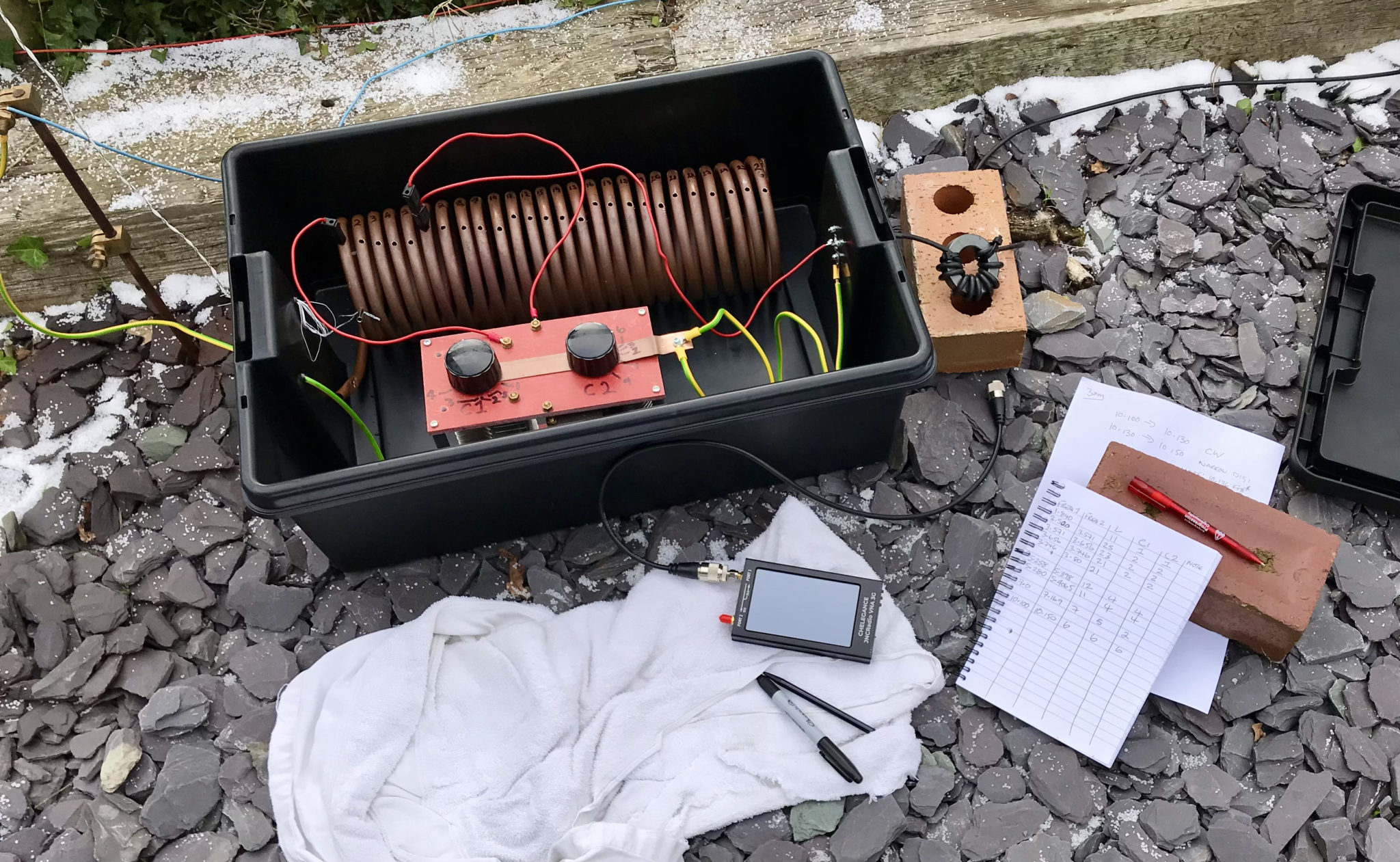
M0AWS Pi-Network ATU using my JNCRadio VNA to find the ATU setting for each band
Having recently purchased a JNCRadio VNA from Martin Lynch and Sons it made tuning the ATU for each band really easy. When it comes to antenna resonance I like my antennas to have an SWR of less than 1.2:1. With the VNA connected it is really easy to tune the antenna for a 1:1 SWR on a particular frequency, make a note of the tune information and then move to the next frequency and start again.
M0AWS Pi-Network ATU Inductor with turns countM0AWS Pi-Network ATU Capacitor 1 and 2 settings
I marked up each turn on the large copper inductor so I could record the position of the input wire onto the inductor. I then added some markings on the two capacitors of the Pi-Network ATU for the resonance points on each band/frequency I wanted to resonate the antenna on.
M0AWS Pi-Network ATU settings noted for each band
After about 40mins I had all the settings recorded on a pad ready for testing from the shack end of the coax run. Connecting my Yaesu FTDX10 to the coax I ran through each band setting checking the SWR as I went. All bands tuned up perfectly 160m through 30m and receiving of Inter-G on the bands that were active was excellent.
Wanting to test the antenna on 40m for the first time I found Nick, M7NHC calling CQ and gave him a call using just 5w output. He came straight back to me and we had a quick chat.
Nick was using an Icom IC-7300 using just 10w into an end-fed long wire from Eastbourne down on the south coast so, we were both QRP. Nick was a 5/7 with QSB and he gave me a 5/8 with QSB, not bad at all consider how much power we were using.
I’m hoping to have a chat with some of the guys from the Matrix this evening on 60m SSB so, it will be interesting to see how the antenna performs on 5Mhz.
Over the years I’ve built many multi band vertical HF antennas including multi-element quarter wave verticals like the DXCommander configuration, multiple end fed vertical dipoles all on the same pole and a host of other configurations. As with all multi band antennas there’s always a compromise, on some bands it performs well and on others it doesn’t, it’s the nature of the beast.
For some time now I’ve been using a multi band vertical antenna that has over the last year performed incredibly well on all bands from 80m to 10m. Don’t get me wrong, it’s not perfect however, it has out performed every other multi band HF vertical I’ve tried to date even though it’s by far the simplest antenna design and according to the antenna modelling software I have it shouldn’t be as good as it is.
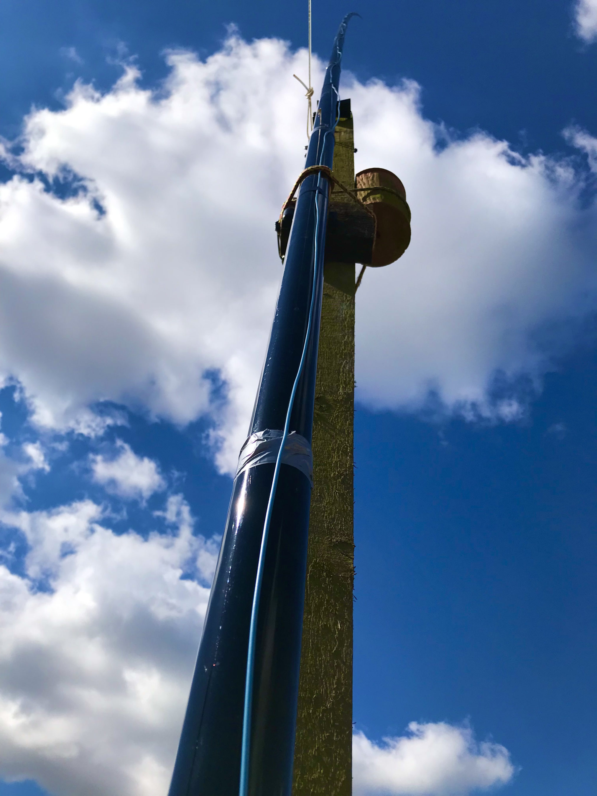
So what is this magical multi band HF vertical I speak of? Well it’s nothing more than a piece of wire 13.4m long taped up a 12.4m vertical Spiderpole with 1m of wire tucked down into the top of the Spiderpole.
Obviously this is not going to be resonant on any band without some sort of impedance matching circuit at the bottom of the wire. Originally this antenna was my end fed half wave vertical antenna for the 30m band that was fed via a 49:1 Unun. This antenna worked incredibly well on the 30m band allowing me to work DX globally with ease but, it was a single band antenna and I wanted a multi band solution.
I decided to remove the 49:1 Unun and replace it with a home brew LC circuit made up of a coil made from 5mm copper tubing and a large air spaced variable capacitor I had laying around from an old ATU project I built many moons ago.
This simple LC arrangement at the bottom of the wire worked incredibly well and tuned the wire from 80m to 10m with a perfect SWR on each band using nothing more than a ground rod and 4 x 12m radials. Performance was surprisingly good on all bands 80-10m giving me the ability to get some DX stations that I’ve never been able to hit before. The only drawback to this solution was the fact that I had to go out and manually tune the antenna every time I wanted to change band. Not so much of a problem in the summer but, in the winter in the pouring rain and howling wind it’s no fun at all. (I resolve this issue further down in the article!)
Multi Band Vertical HF Antenna using a 12.4m Heavy duty Spiderpole at the end of the garden
Performance on the HF bands is incredibly impressive with this antenna. Modelling it on EzNEC software it shouldn’t be that great on bands above 20m however, it seems to defy the modelling software as it performs amazingly well on 17m, 15m and 12m, better than any other vertical antenna I’ve made for those bands. How this can be I do not know, normally my antenna builds match closely what the modelling software shows but, in this instance it doesn’t and I’ve really no idea why.
Multi Band Vertical HF Antenna showing loop at top and wire tucked down into pole
Always wanting to put things into perspective here’s some details of the contacts I’ve made on each band showing how well this antenna has performed over the last year or so.
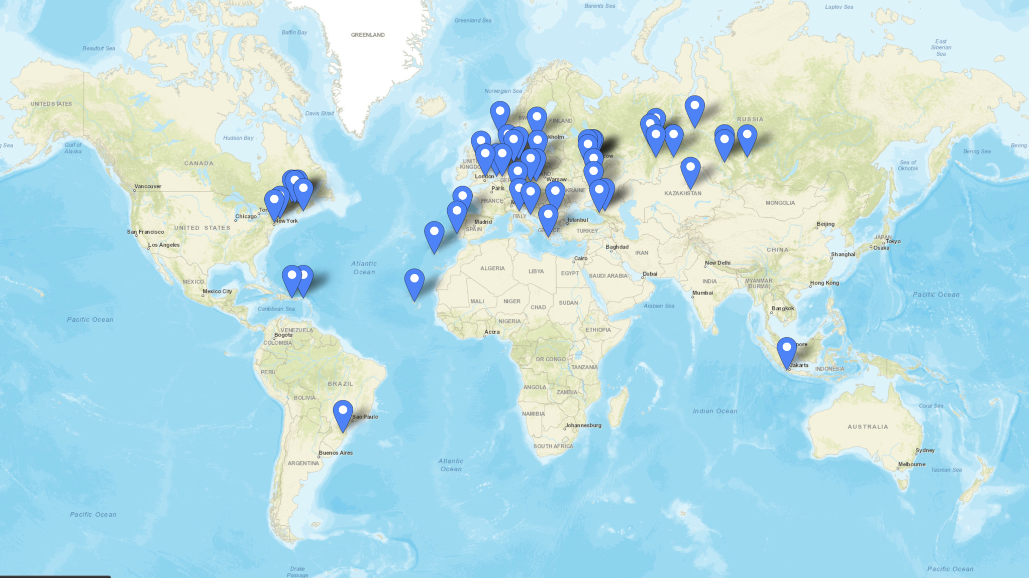
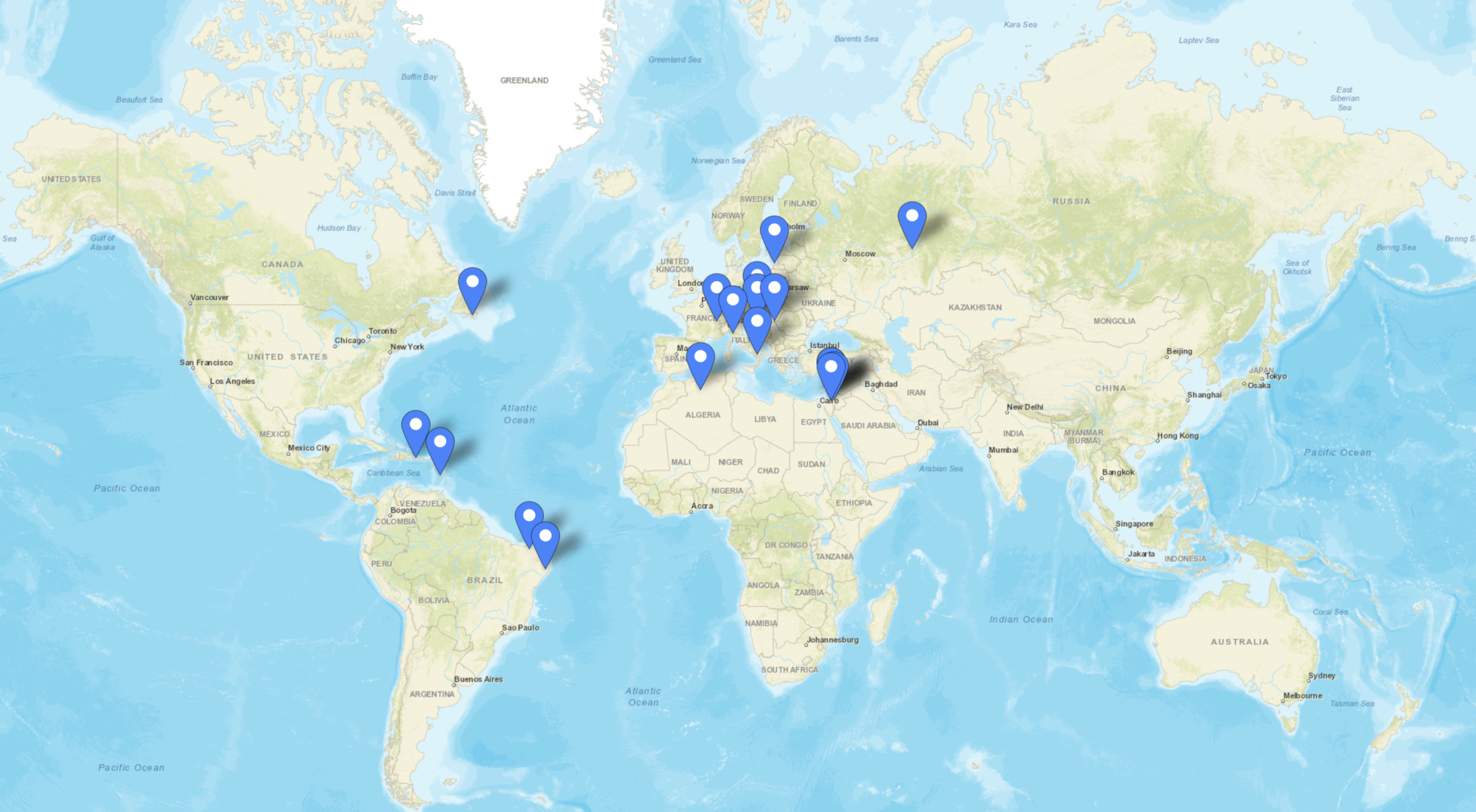
Firstly the 80m band, I’ve not used this band much over the winter months as I’ve got into the higher bands however, the map below shows all the stations worked on 80m using this antenna.
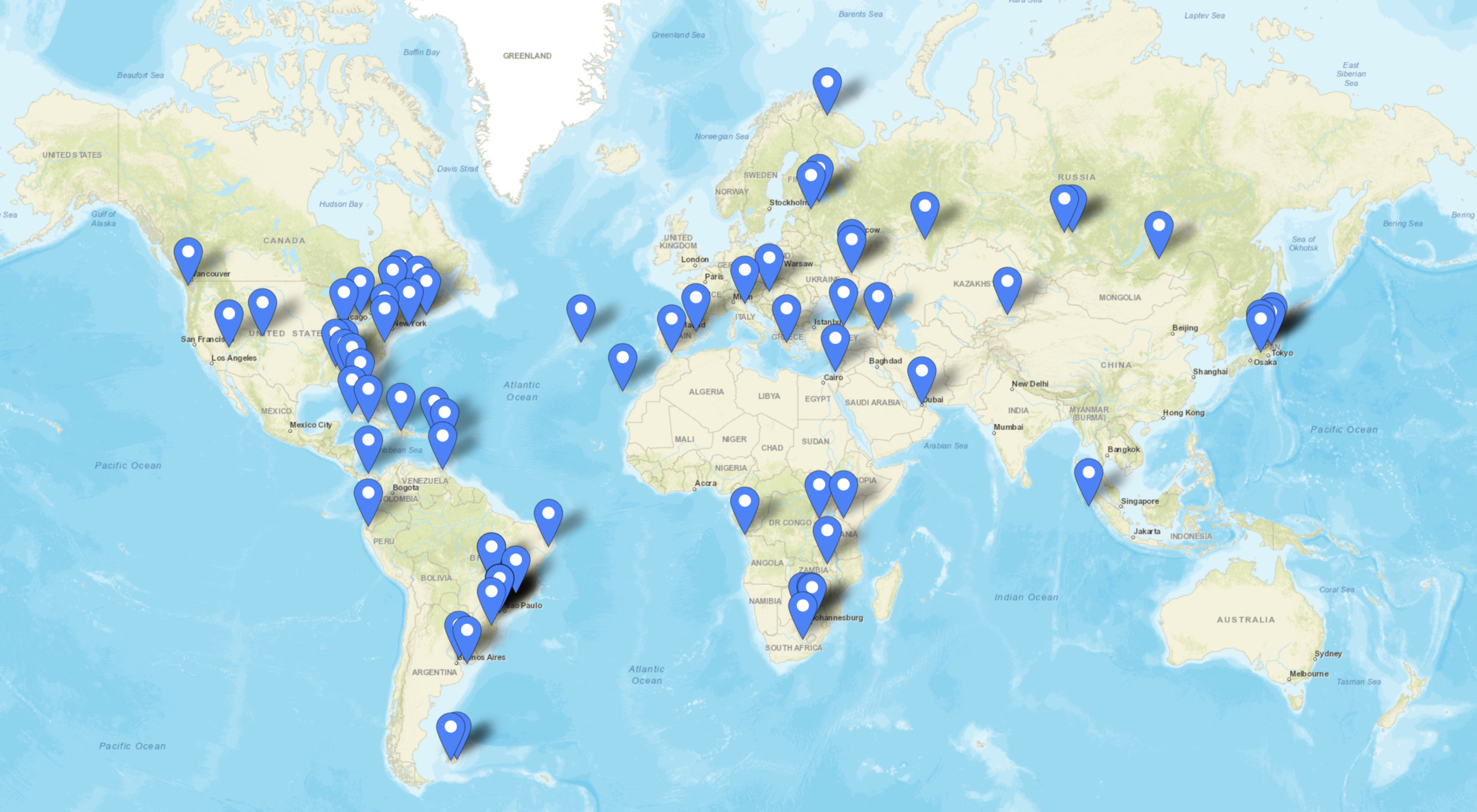
Stations worked on the 80m band from the M0AWS QTH
There are 51 contacts in total, not a big number by any means however, there are some good distances made with contacts into North America, South America and Indonesia. I’m sure I could had done better if I’d spent more time on this band, something to aim for next winter perhaps.
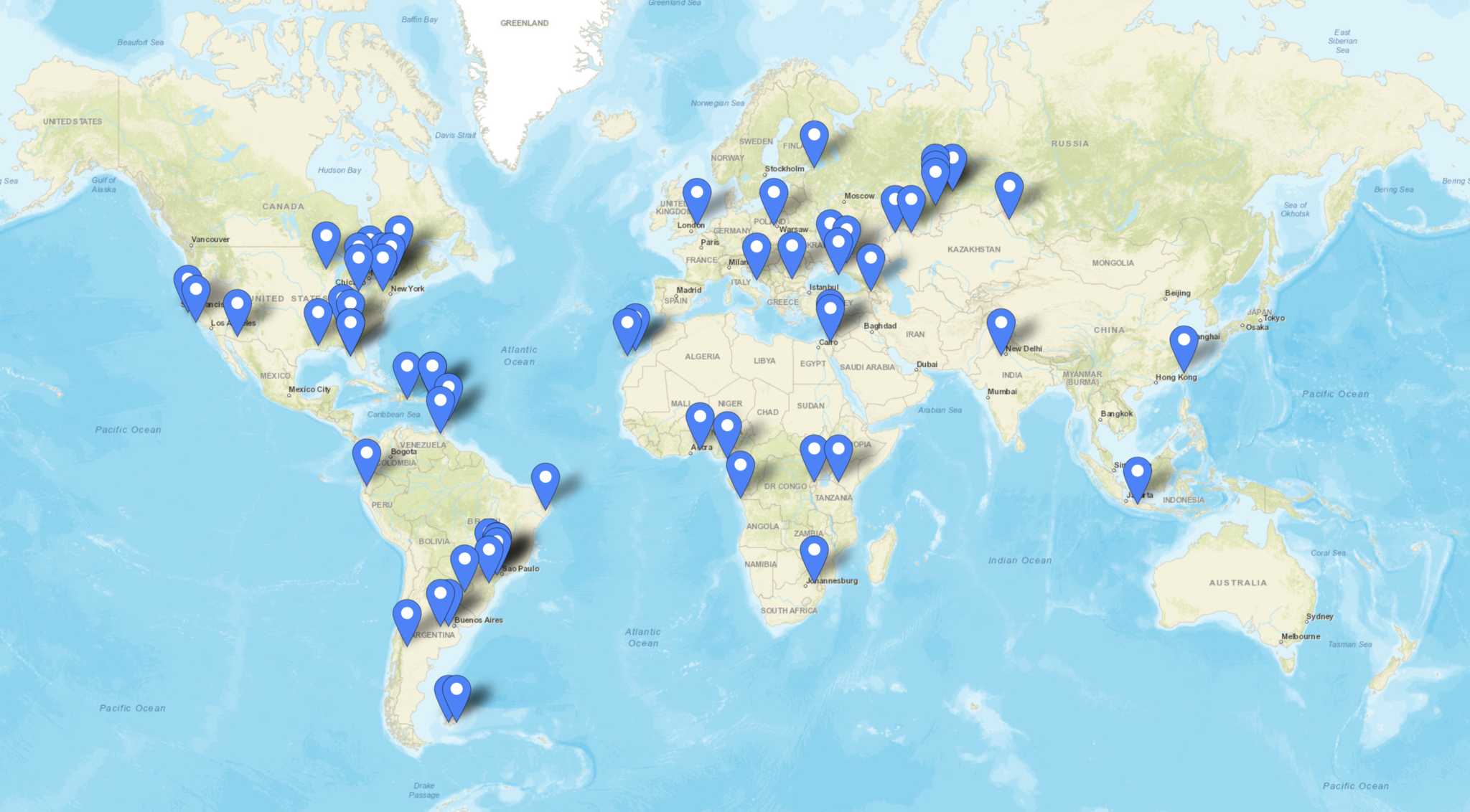
Next is the 60m band, a band I really like and have enjoyed over the winter months. The antenna performs incredibly well on this band even though we have very limited access to 60m here in the UK. With 288 contacts in the log with a good spread of distances I’m really pleased with how this antenna performs on this band.
Stations worked on the 60m band from the M0AWS QTH
Moving up in frequency the 40m band is the next one on the list, this is a great band and one that I’ve loved for many years. I’ve spent countless hours on CW on this band in the past and worked some great DX. The performance of this antenna on the 40m band is excellent, if I can hear the DX normally I can work them regardless of where in the world they are located. With 226 contacts in the log spread globally over the winter here in the northern hemisphere I have no complaints about performance of this antenna on the 40m band.
Stations worked on the 40m band from the M0AWS QTH
Moving up onto the 30m band I have to admit this is probably my favourite band of all. I’ve spent so many hours on CW working some of the best fists I have ever heard on the air I’ve grown to love this band not just for the DX available but, for the quality of operator found on this narrow piece of the RF spectrum. Needless to say since the antenna is a half wave on the 30m band performance is stunning, out performing any other 30m band antenna I have ever made. It’s even better than the 30m Delta Loop antenna that I built and used when I lived in France.
With 467 contacts in the log on the 30m band you can tell this is my goto band and one that offers access to some of the best DX in the world.
Stations worked on the 30m band from the M0AWS QTH
The 20m band is a band that I never really used until I moved back to the UK from France. Living in France I had acres of land and so I was very much into the low bands, 160m to 30m and never ventured above this part of the spectrum. Now living back in the U.K. with a typical U.K. sized garden the low bands are much more difficult to get onto and so my interests have moved up in frequency somewhat.
Getting onto the 20m band I was amazed at how easy it is to work DX stations compared to the low bands, it’s simply a case of if you can hear them you can work them, there’s no real challenge to be honest. Because of this the band is always super busy with people shouting over the top of each other to get the DX. Not to be put off, I’ve made a surprising 412 contacts on 20m covering the globe. This antenna works incredibly well on this band and you really don’t need anything else to work DX on 20m.
Stations worked on the 20m band from the M0AWS QTH
Next is the 17m band, one of the WARC bands that I’ve never really ventured onto until now. I have to admit I really like this band, when it’s open it’s normally open to the world all at the same time. With an almost undetectable background noise level you can hear the faintest of signal on this band. This is one of the bands that according to the EzNEC modelling software this antenna shouldn’t be any good on but, I have to say that it’s performance is beyond anything I ever imagined. I’ve worked my longest distance yet on this band and with this antenna, ZL4AS at 11776 miles, a distance I haven’t achieved yet on any other band. The 17m band really is a great band, I’d actually say it’s better than the 20m band even though there is considerably less spectrum available. With 220 contacts in the log it’s been a fun band to use.
Stations worked on the 17m band from the M0AWS QTH
Continuing the theme of the WARC bands, the 15m band is another one that I’ve only discovered in the last 12 months. It’s only now that I realise what I’ve missed out on due to my addiction to the low bands for so many years.
I’ve only made 76 contacts on the 15m band, not a lot at all really. This is mainly due to the fact that I get easily side tracked by the 17m and 30m bands most of the time and the radio VFO never gets as far as 21Mhz. Performance of the antenna is good on 15m, I would say not as good as on the 17m band but, it’s no slouch by any means.
As you can see on the map below, I may of only made 76 contacts on the 15m band but, they are spread right across the world proving that this antenna’s DX-ability on 21Mhz really is rather good.
Stations worked on the 15m band from the M0AWS QTH
Finally we arrive at the top of the WARC bands, the little 12m band. Once again this band is very much like the 17m band, super low background noise level, when it’s open you can work huge distances with very little power but, often there is quite deep QSB that can make getting that elusive DX a bit more challenging.
With only 66 contacts in the log once again I’ve not spent a huge amount of time on this band but, it hasn’t disappointed. With global coverage from this antenna on 12m once again I am astounded at how well it works. With software modelling saying it should be terrible on 24.9Mhz with nothing but super high angle radiation, it really shouldn’t be a good antenna for DXing on this upper WARC band but, it is and I have no idea as to why!
Stations worked on the 12m band from the M0AWS QTH
Finally we arrive at the 10m band, another band that I have never got into even though many refer to it as the magic band. This is the band that I’ve made the fewest contacts on, not because the antenna doesn’t work at the dizzy heights of 28Mhz but, because I hardly ever get the VFO dial past the lower bands due to the level of DX available. I really should make more effort to get the best out of the 10m band, especially now the summer is coming.
With a measly 19 contacts in the log I should be ashamed of myself for not doing more on this band as it is very often open and busy with traffic. Since I’ve not really used the antenna that much on the 10m band it’s hard to say how well it performs however, I have had contacts into North and South America and so it shows potential.
Stations worked on the 10m band from the M0AWS QTH
As you can see, the performance of this antenna is self evident from the log entries, it works superbly even though the modelling software says it shouldn’t above 14Mhz. This is now my main antenna here in the U.K. and I’ve only made one change to the initial setup and that is to add a CG3000 remote auto ATU to replace the home-brew LC tuning circuit.
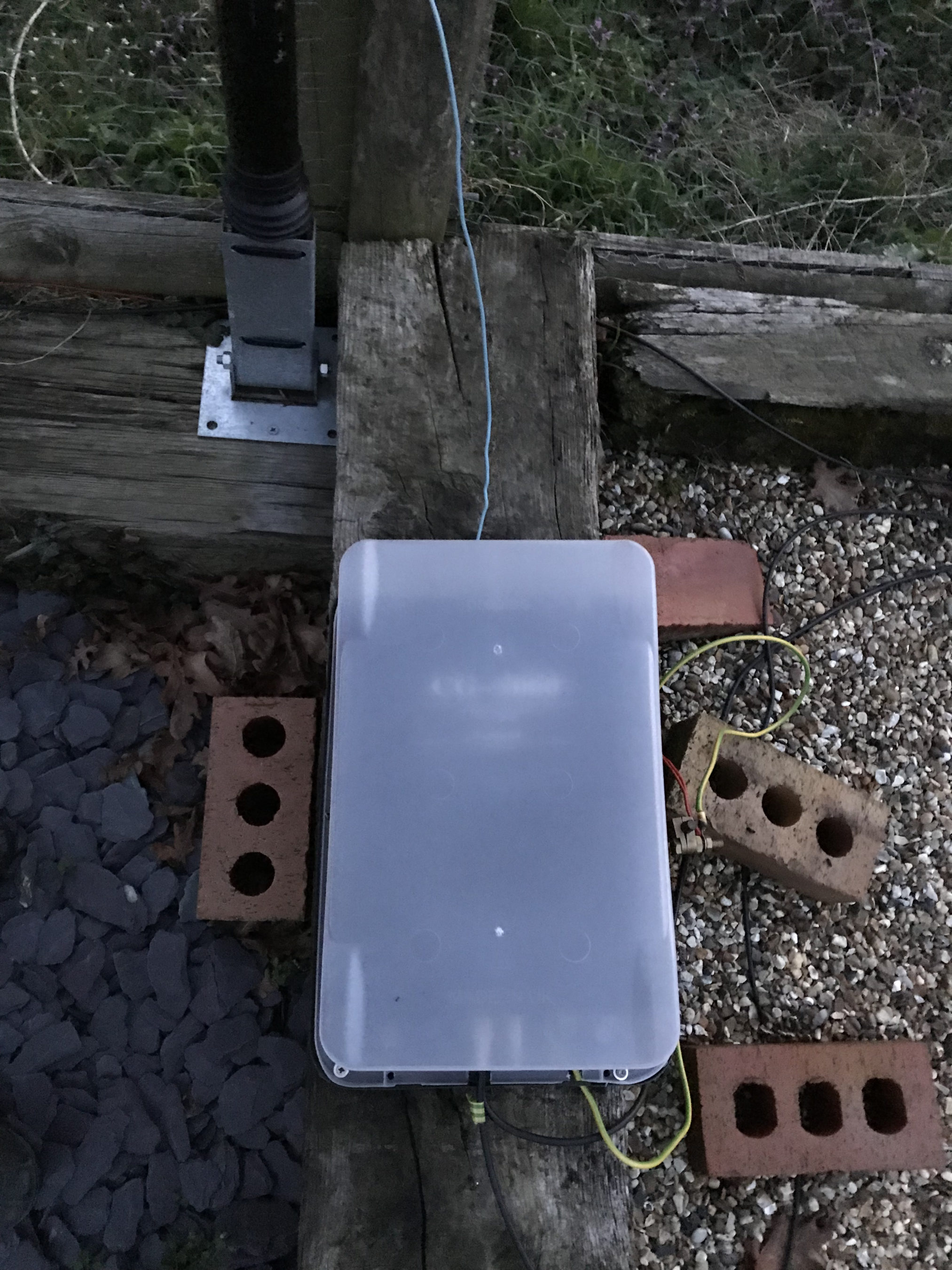
CG3000 Remote Auto ATU housed in a plastic box
With the CG3000 auto ATU in place I no longer have to venture out into the cold, wet garden in the winter months to change band, it’s just a case of sending a continuous 10w signal into it and leaving it to tune in less than 2 seconds. The CG3000 is a Pi Network ATU so it handles both high and low impedance loads with ease. A Pi Network ATU is one of the best you can have, I’ve made my own in the past and had excellent results.
So in summary, 13.4m of wire vertically up a 12.4m pole with 4 x 12m radials, a ground rod and a CG3000 Auto ATU will give any HAM station the ability to work DX on all bands from 80m to 10m without ever having to leave the shack to tune it.
Since I got the CG3000 off of Ebay for a bargain £170 and the 12m heavy duty Spiderpole for under £100 the total cost of the antenna is considerably less than many commercial offerings available and yet performs as well if not better.
If you want to get this antenna onto the 160m band then you just need to add a small coil into the mix at the bottom of the wire to increase the inductance in circuit. The CG3000 will then happily tune the entire 160m band. It’s best to remove this coil though for all the other bands otherwise performance is reduced.
Please be aware that the performance of this antenna will not be anywhere near as good if you use the ATU in your radio at the end of a coax run. This is because the coax becomes part of the antenna and the radiation pattern is all but destroyed. You will be extremely disappointed if you use the antenna in this fashion. The ATU must be at the end of the wire and connected directly to ground and the radials to get the performance that I have experienced.
Finally, if you have an Icom IC-705 and AH-705 remote auto ATU you can use the AH-705 ATU in place of the CG3000, you will get the same results as I have with the CG3000.
I have used my AH-705/IC-705 combo quite a few times with this antenna with excellent results although, the big antenna can sometimes result in the receiver of the IC-705 getting overloaded especially on the lower bands. This is easily resolved by reducing the RF Gain on the radio.
I’ve been chasing the DX on the HF bands using FT8 for a while now and I have to say it’s been very successful however, it does get rather boring after a while just exchanging SNR reports and nothing else. I noticed that my time spent in the shack was getting less and less, not a good sign after all the work I’d put into building the new radio shack.
Since there’s not a lot of CW on the bands these days (everyone is on FT8) I thought I’d give JS8CALL a go.
Initially I started with trying to get JS8CALL working on my Kubuntu PC to my Icom IC-705 wirelessly. This turned out not to be as straight forward as I’d hoped but, I persevered.
I found that to communicate with the IC-705 via WFview wirelessly I needed to use FLRig as a go between. I installed FLRig from the Ubuntu repo’s only to find it’s an old version that doesn’t have support for the IC-705. Downloading the IC-705.xml file didn’t help either so I uninstalled it and headed to the source forge website to grab the source code for the latest version of FLRig.
Once I had the right development libraries installed compiling the code was easy enough and I soon had FLRig talking to the IC-705 via WFview wirelessly from my Kubuntu PC.
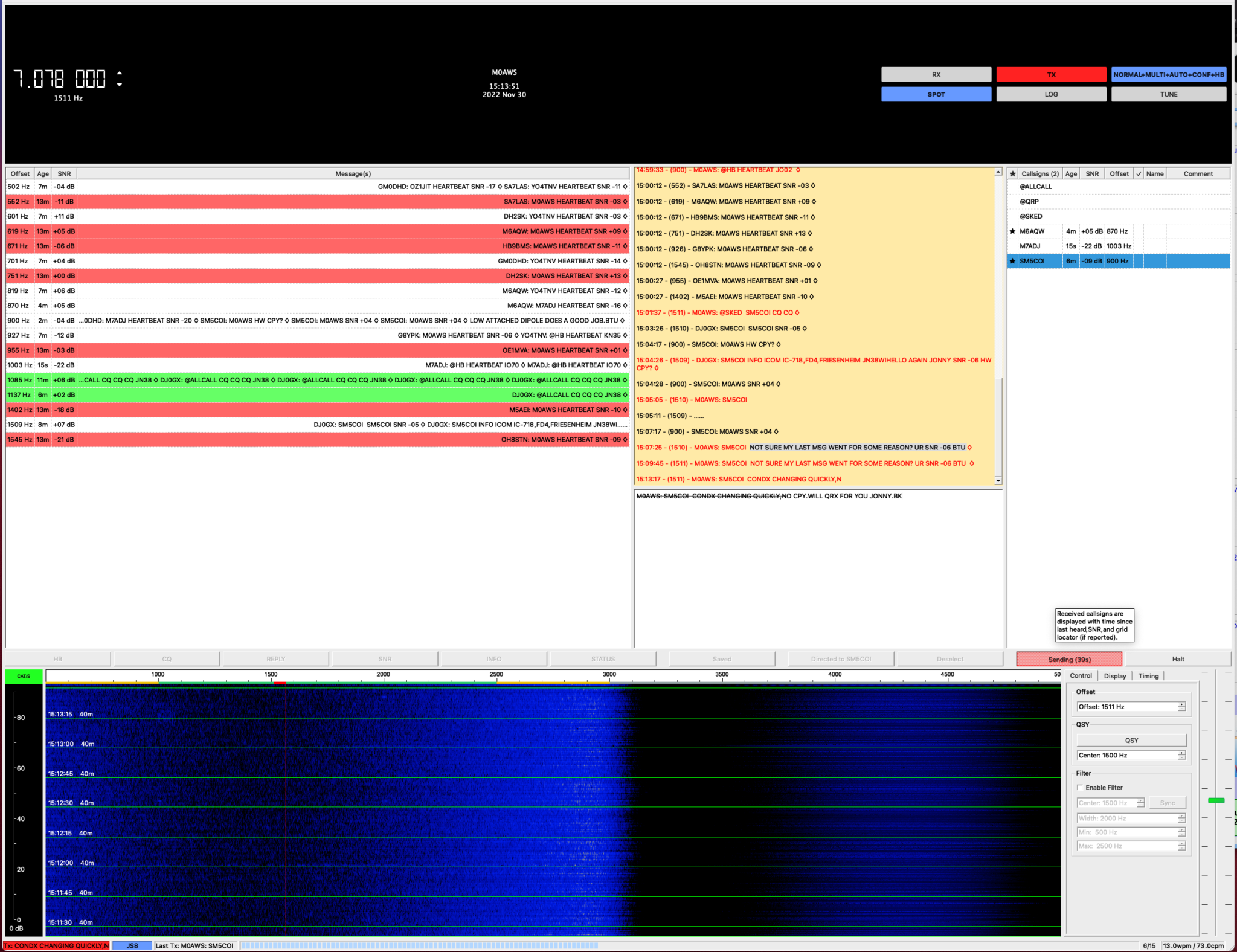
My first JS8 QSO was with Jonny, SM5COI in Sweden on the 20m band, using just 2.5w I had a very reliable link from my 20m band EFHW vertical antenna to his 20m band yagi antenna.
I also worked GM0DHD/P via OH8XAT using the relay capability built into JS8CALL, it works incredibly well and allows you to work the stations that you cannot hear directly, very useful!
Later in the morning Jonny, SM5COI emailed me asking for a sked on the 40m band later in the afternoon, of course I agreed and decided that I’d also get my MacBook Pro setup with JS8CALL so I could give my Yaesu FTDX10 a spin on JS8 mode.
Installing and configuring JS8CALL on my MacBook Pro was much easier and I had it fully operational in minutes.
The sked went well on 40m and it was good to get Jonny on another band.
With 3 JS8 QSOs in the log it’s great to be using a digital mode again that allows you to have a good chat with other radio HAMs around the world. I think this may become my preferred digital mode going forward.
I spent the evening/early morning trying some FT8 on the 40m band taking advantage of the grey line and night time propagation. It’s been a while since I’ve stayed up late to catch some DX on 40m and it brought back memories of the all nighters I used to do when I was on air as F5VKM in France.
The 40m band has always been one of my favourites, there’s always great DX to be had when the band is open and on the grey line the world really is your oyster.
I’ve always been a huge fan of CW on 40m, there are some great seasoned op’s on the band and it’s always a real pleasure to QSO with them on the key. This time I decided to see what could be achieved with FT8 and 22w of power from my Yaesu FTDX10, a combination that should give me global reach.
Setting up at just past 6pm on May 9th 2022 the band was already busy with European stations, lots of them! There was no room to squeeze in and call CQ, the FT8 section of the band was packed with signals filling the allocation completely with many calling over the top of each other.
I decided to take my normal stance of search and pounce to get the stations I want to work rather than just working the masses endlessly.
I initially worked a bunch of Russian stations ranging from 1200 to 2200 miles out, good distances were easily achievable even though we were still in full daylight.
My home-brew multi-band vertical antenna worked well on 40m
In amongst the throng of FT8 stations I spotted UN3P, Vladimir in Karaganda Kazakhstan, not a country I have worked a lot since getting back on air and at 3013 miles it’s a good distance to achieve on 40m whilst still in broad daylight.
I gave a call to his CQ and he came straight back with an SNR report of -20dB, I sent him a report of -12dB so there was some 8dB difference between us. Considering I was only using 22w of power in broad daylight I was happy with the report. Of course I’ve no idea how much power he was using but, my signal was 6.63mW/Mile, not the lowest I ever had but, not the biggest either.
I worked a bunch more RA9/UB9 stations in the 2000-3000 mile range and then started hearing the Australian stations on the early grey line. Initially their signals were suffering some deep QSB but, it wasn’t long until their signals were constant and stable.
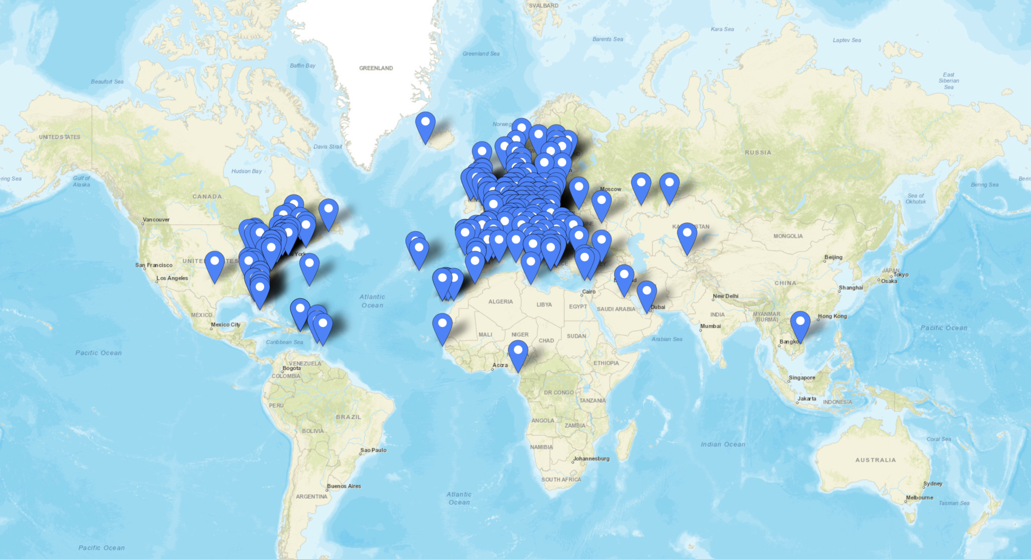
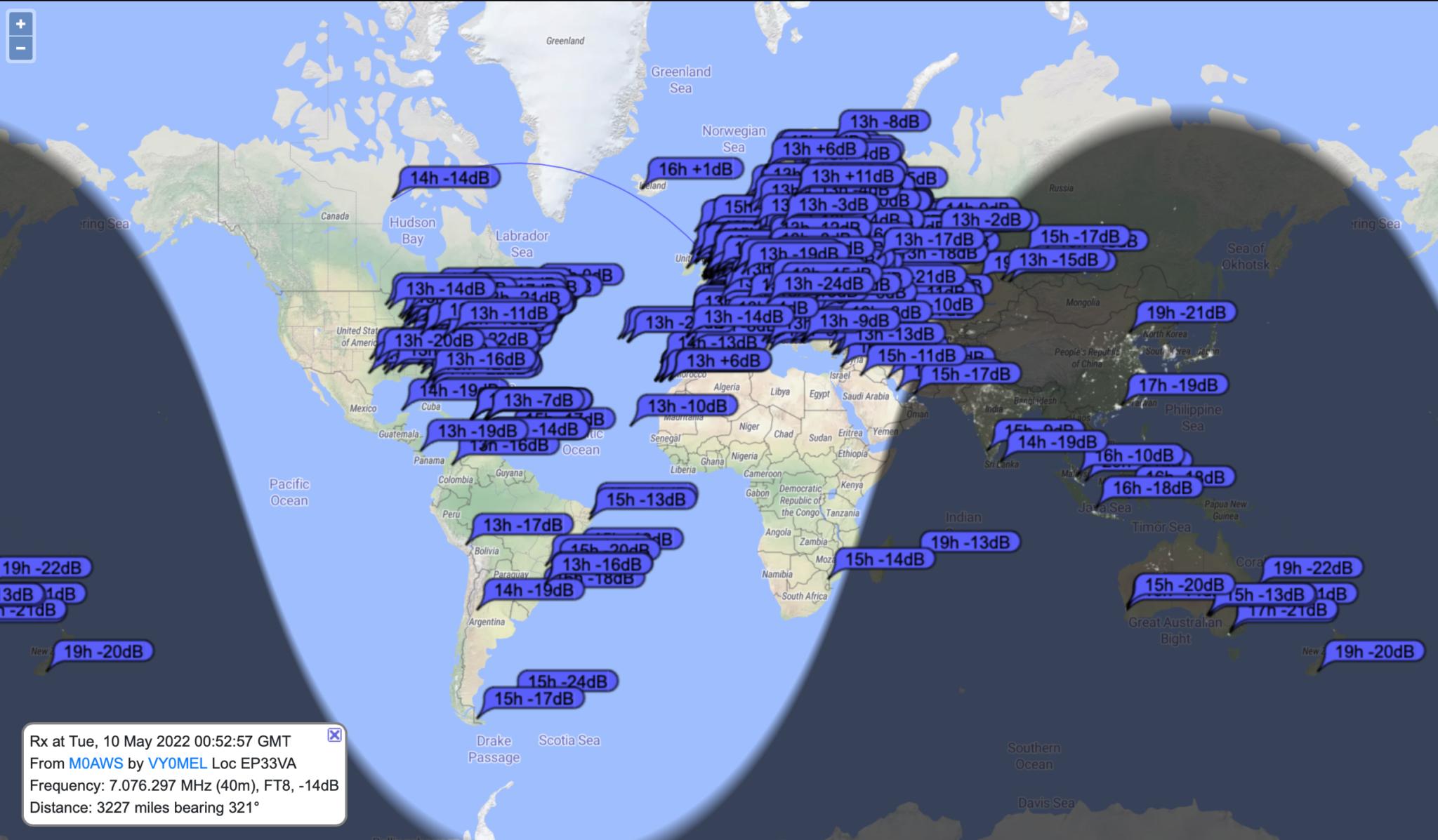
All the stations that heard M0AWS 09/05/22 – 10/05/22 on 40m
Ian, VK3VDX in Victoria was the first station from Oz in the log at -19dB/-20dB, pretty even SNR reports. At 10451 miles it equates to 2.10mW/Mile.
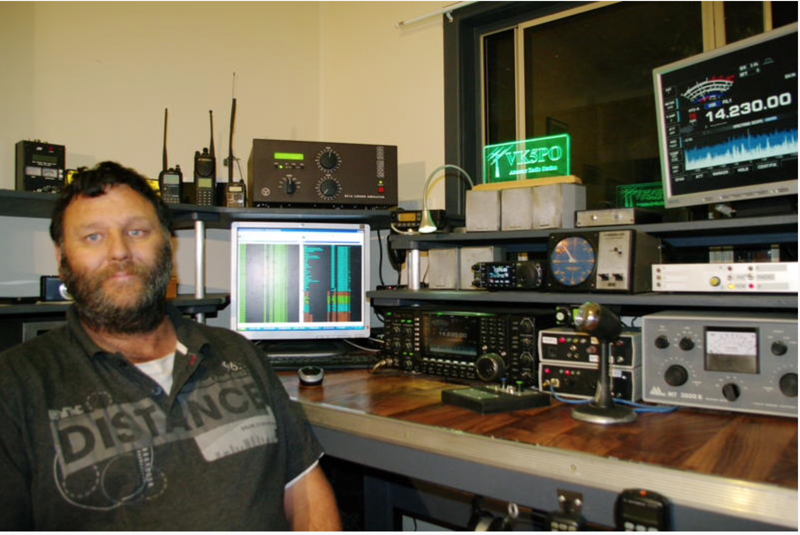
Closely following was John, VK5PO in Mallala South Australia, much stronger signals this time at -10dB/-14dB, 2.19mW/mile over a total distance of 10028 miles.
VK5PO Mallala South Australia
As darkness replaced light the propagation swung west with east coast USA and Canadian stations dropping in to the East coast of the U.K.
John, VO1BE was the first north American station in the log with -1dB/+1dB SNR reports. To be +1dB in Canada with just 22w really is quite impressive. I’m guessing he has a very low background noise level.
I worked a bunch of East Coast USA stations and then PY2GZ popped up on the waterfall. From my QTH I have a clear view South East to South West across flat ground for miles and so it’s normally pretty easy to work stations in that zone and this evening was no different. First call was answered and -10dB/-17dB SNR reports were exchanged, 3.68mW/mile over 5965 miles.
My 14.81m tall home brew vertical works superbly on the 40m band with tuning handled by my CG3000 Remote Auto Tuner. This is actually my 30m band EFHW vertical antenna but, removing the 49:1 Unun and replacing it with the CG3000 has made this antenna much more versatile.
CG3000 Remote Auto Tuner connected to the 14.81m vertical antenna and ground system
The next station in the log was BG0BBB in Xinjiang China with -9dB/-18dB SNR reports exchanged. China is always a hard location for me to get into for some reason so, I was glad to get another Chinese HAM into the log.
BG0BBB Xinjiang China
As the propagation started to swing westerly I got 8P4JP in Bridgetown Barbados into the log. It took a few calls to get the exchange completed due to very deep QSB between us but, with some perseverance the contact was completed successfully and I had a new one in the log!
I continued to work a flurry of East Coast USA, Brazilian and Puerto Ricon stations one after the other until suddenly stations from the east started coming in again.
First from the east was Igor, 4L1FL from Tbilisi Georgia, another new one for me that somehow seems to escape me every time I come across Georgian stations on the bands.
4L1FL Tbilisi Georgia
UN7JO in Ust-Kamenogorsk Kazakhstan was loud with me at -5dB SNR although I only got -21dB SNR back, some 16dB difference across the path of 3386 Miles.
One station of particular interest was VY0MEL, Julien in Rankin Inlet, Nunavut Northern Canada. This is the most northern Canadian station I’ve worked in a long time and it was great to get him in the log. His QRZ page is worth a read, he works at a mine in Nunavut on a 14 day rotation and so has a fair bit of time for HAM radio. Using just a dipole that is strung between two shipping containers and only 60cm above the snow in the centre he was a good signal at -19dB here in the U.K, especially considering he was still in broad daylight.
VY0MEL Rankin Inlet, Nunavut Northern Canada
Needless to say I had a fun filled evening/early morning on the 40m band, once again it didn’t disappoint and I got a couple of new countries in the log. I think the next late night will have to be a CW evening on 40m to see how well I do in comparison.
The full list of stations worked over 9th-10th May 2022 using FT8 on the 40m band can be viewed in my WSJT-X log in glorious technicolour with distances and mW/mile figures for every contact.
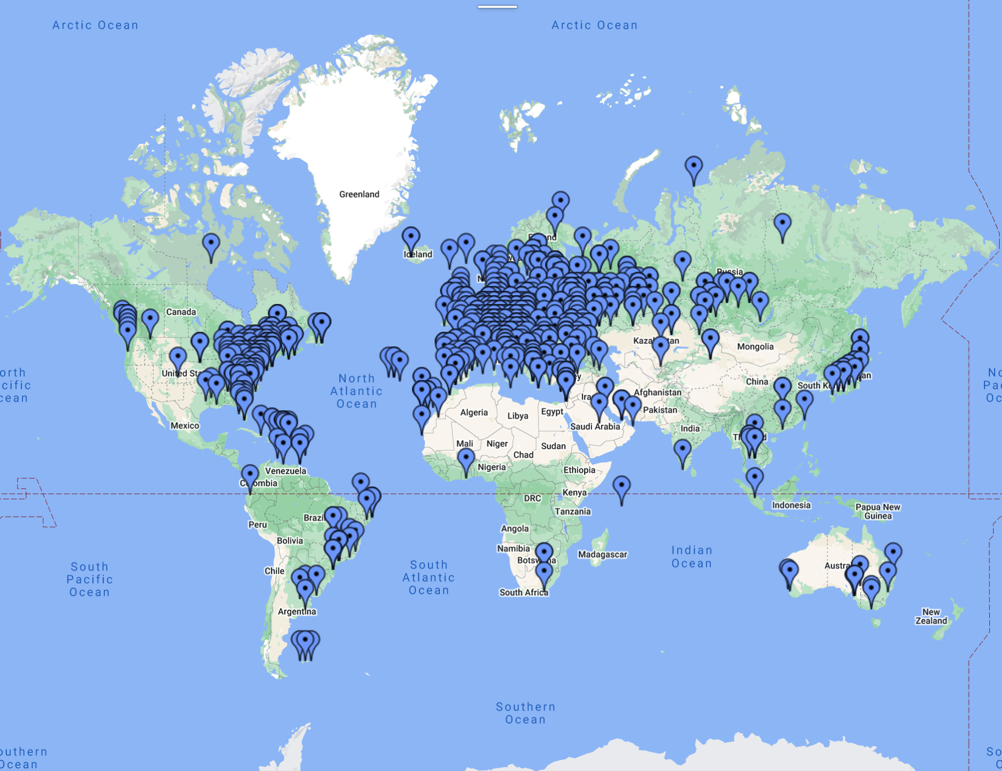
Map showing all FT4/FT8 stations worked up to 10/05/22 all bands
More soon …
We use cookies to ensure that we give you the best experience on our website. If you continue to use this site we will assume that you are happy with it.