A closer look at my Inverted-L Antenna performance

For some time now I’ve been using an Inverted-L style antenna, albeit not a perfect L but, I have found it to perform extremely well.

When I put the antenna up I was aiming for good NVIS radiation on 80/60/40m for chatting Inter-G and local EU stations <1000 miles from my QTH.

I wasn’t expecting good performance on the higher HF bands as the total length of wire is 37m which is somewhat long for the higher frequency bands however, I’ve found performance around Europe to be very good and extremely good over the north pole to Oceania and the USA.
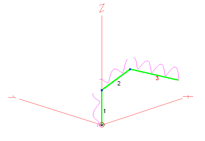
M0AWS Inverted-L style Antenna

As you can see from the antenna view above, it’s not a perfect inverted-L by any means however, its shape has actually proven to be advantageous.

Wire 1 is 9m tall, it then goes approximately 10.5m in length up to a peak of 12m above ground in the centre, this is where I have a 12m Spiderpole for support. From there the remaining 17.5m of wire slopes down to 5m above ground and is attached to the back of the house via a large insulator. Total wire length is 37m.

Wire 1 is at the bottom of a South facing garden and direction +X is north.

The antenna is tuned at the bottom of wire 1 using my CG3000 Remote Auto ATU at ground level. There are a number of random length radials hidden in the lawn and around the perimeter of the garden running mainly from South to North. I cannot run any radials to the south (-X) as this is farmland and not owned by me.

The radio I use is a Hermes Lite 2 SDR paired with a Xiegu XPA125B 100w amplifier. I normally only use 80w or less on all bands and so, my results are achievable using any 100w radio.

On the low bands I find it has great NVIS performance with excellent signal reports from all over the UK and out to around 1500 miles into Europe and beyond. This is exactly what I wanted from the antenna and I’ve been very pleased with it’s performance on 80/60/40m.

Looking at the 2D Far Field Plots on the 3 low bands the antenna has a typical NVIS high angle of radiation pattern with some gain.
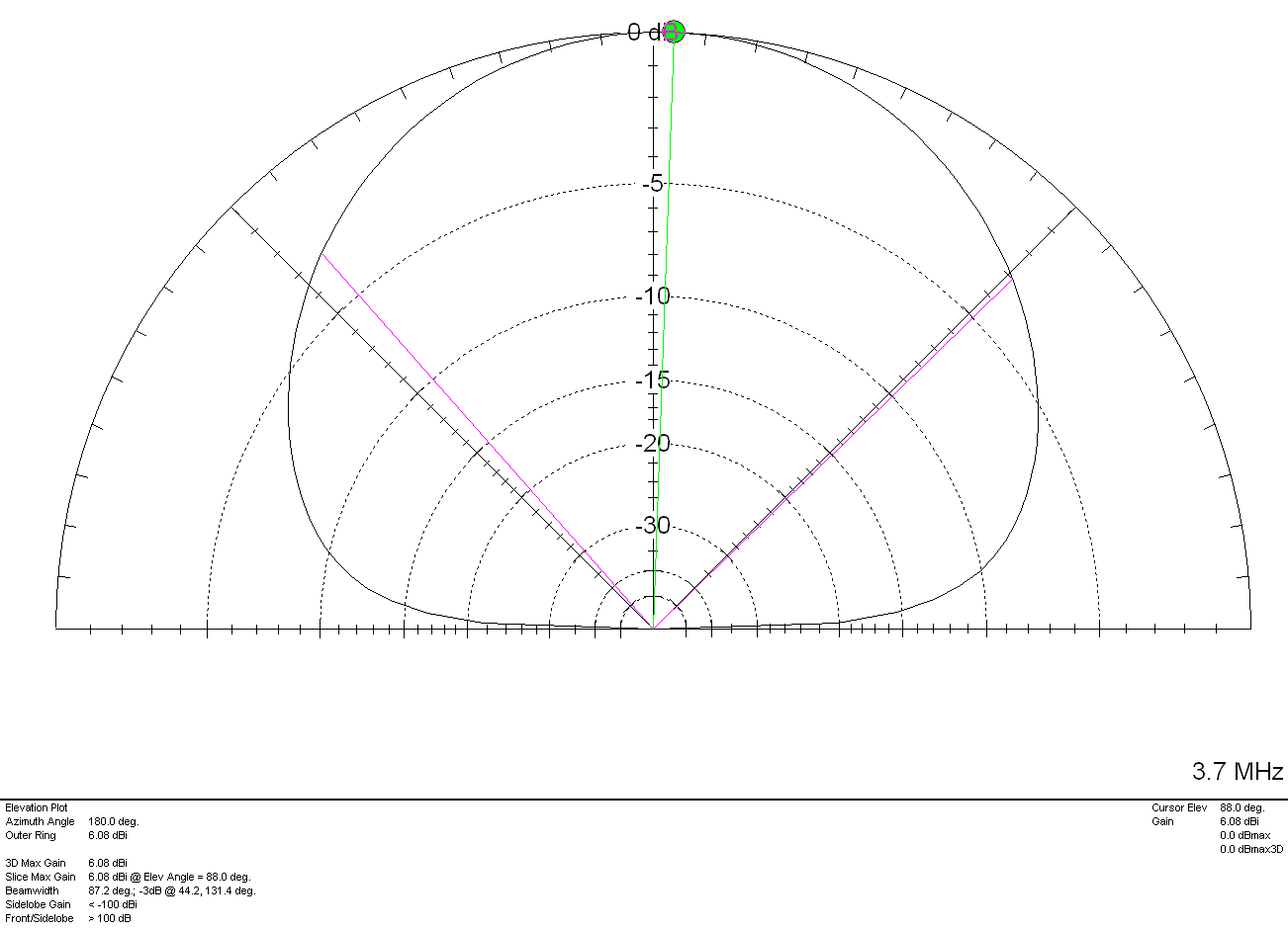
M0AWS Inverted-L Style Antenna 2D Plot on the 80m Band

On the 80m band maximum radiation is straight up, as expected with a gain of 6.08dBi (3.58dBd). The gain reduces at lower angles however, it still performs well out to around 1500 miles and occasionally even further.
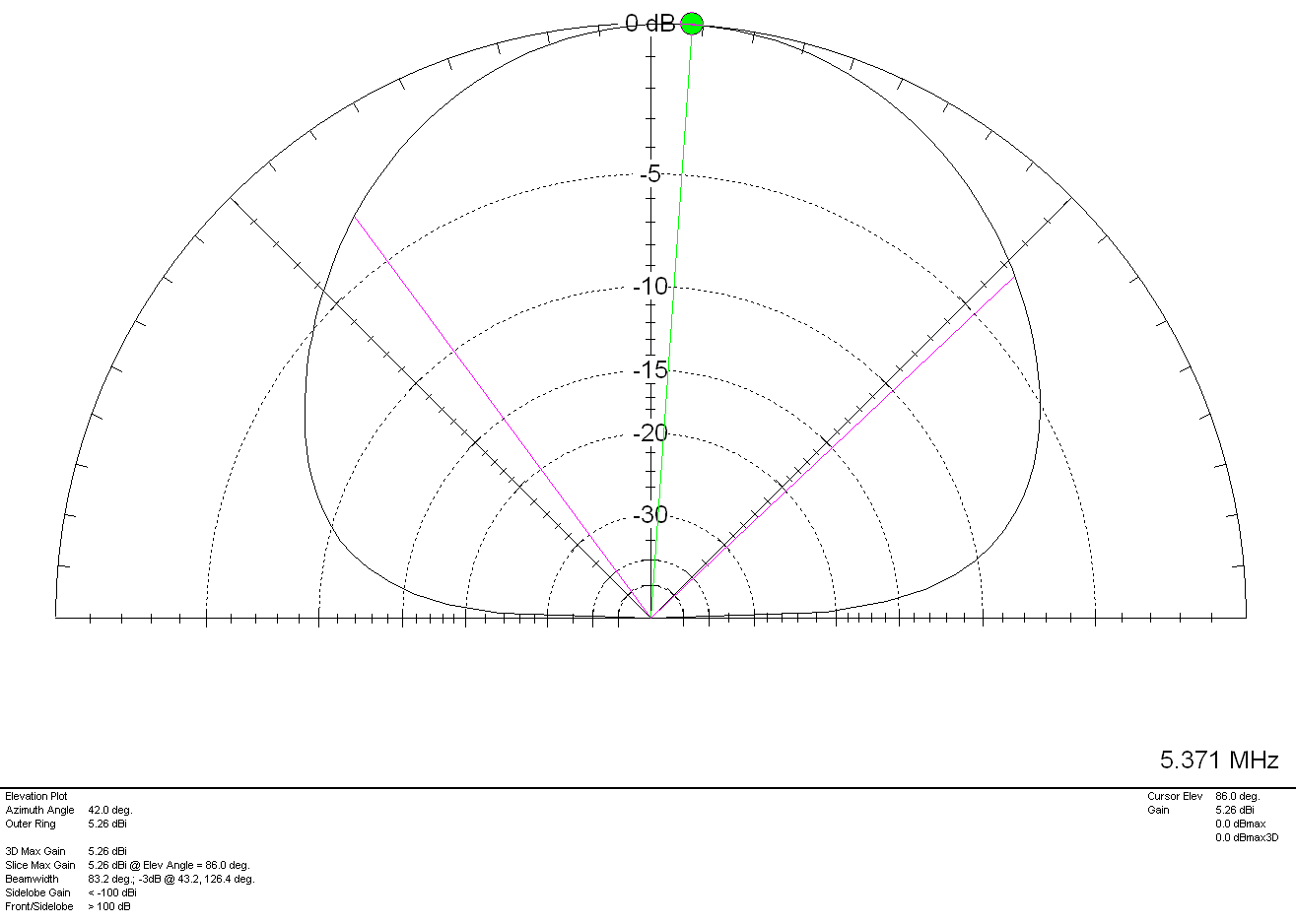
M0AWS Inverted-L Style Antenna 2D Plot on the 60m Band

Once again on the 60m band maximum radiation is pretty much straight up as expected however, I have worked in to Canada many times on 60m with excellent signal reports and so, it also has good DX capability too. With 5.26dBi (2.76dBd) gain it’s not a lossy antenna by any stretch of the imagination.
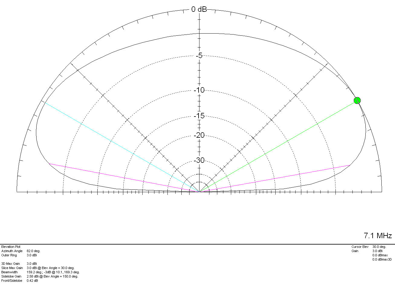
M0AWS Inverted-L Style Antenna 2D Plot on the 40m Band

On the 40m band things start to change a little with the angle of maximum radiation being at 30 degrees rather than straight up. This gives the antenna “longer legs” on the 40m band making it very easy to work longer distances. It’s still very good for Inter-G but, performance over longer distances is considerably better. With a gain of 3.0dBi (0.5dBd) it’s performance is similar to that of a dipole at a similar height above ground.

Above 7Mhz things start to change considerably. The antenna becomes directional to the North West (NW) and North East (NE) giving excellent DX results over the North Pole into North America and Australia/New Zealand. The antenna does of course also have an element of high angle radiation making it useful into Europe and North Africa on the higher bands.
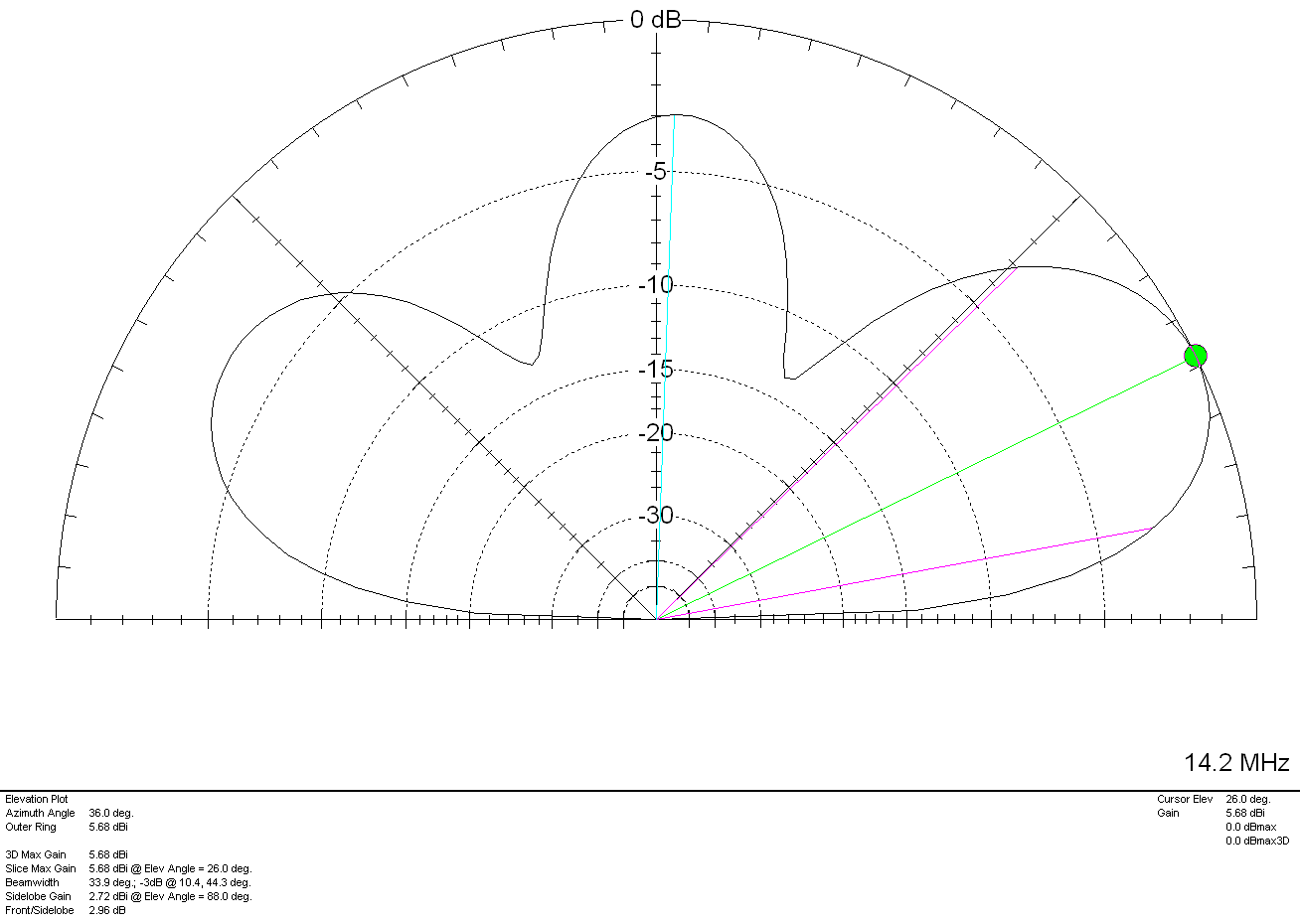
M0AWS Inverted-L Style Antenna 2D Plot on the 20m Band

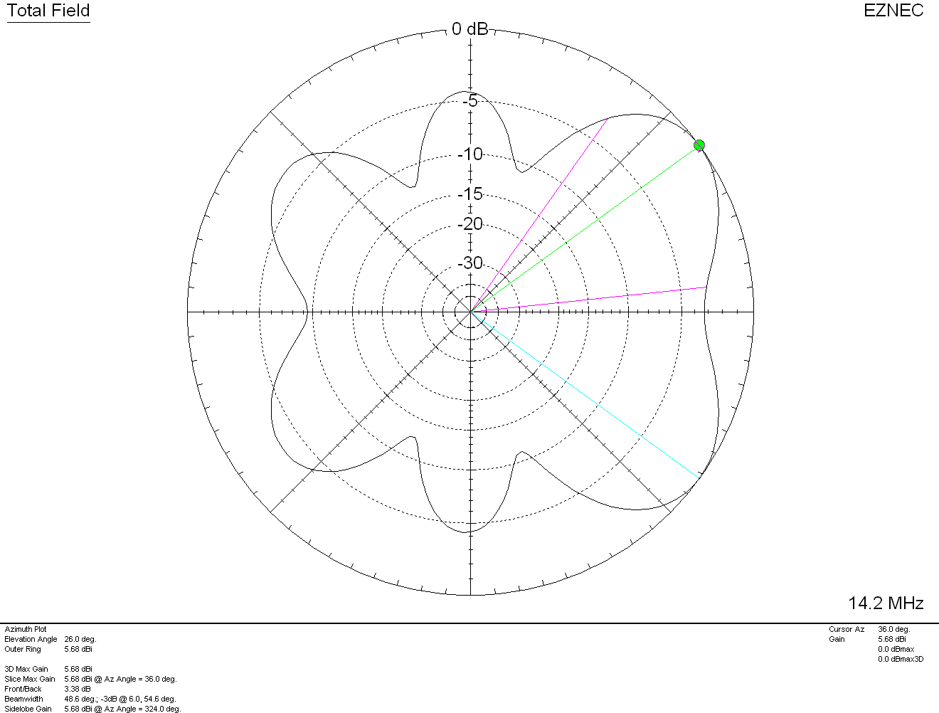
On the 20m band the maximum radiation is at 26 degrees with a gain of 5.68dBi (3.18dBd) pointing NW and NE. There is a lower gain lobe to the South West (SW) and South East (SE) giving excellent coverage through Europe and into Africa as can be seen in the 3D Far Field Plot and Azimuth Slice shown below.
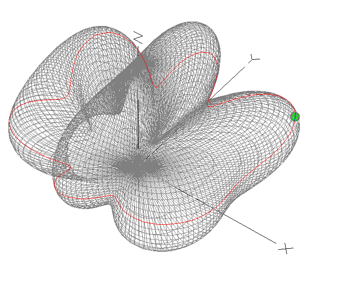
M0AWS Inverted-L Style Antenna 3D Plot on the 20m Band
M0AWS Inverted-L Style Antenna 2D Azimuth Slice on the 20m Band

Moving up in frequency to the 17m band the 3D Plot and Azimuth Slice are similar to that on the 20m band but, with a slightly lower angle of maximum radiation and slightly more gain as can been in the 2D elevation plot shown below.
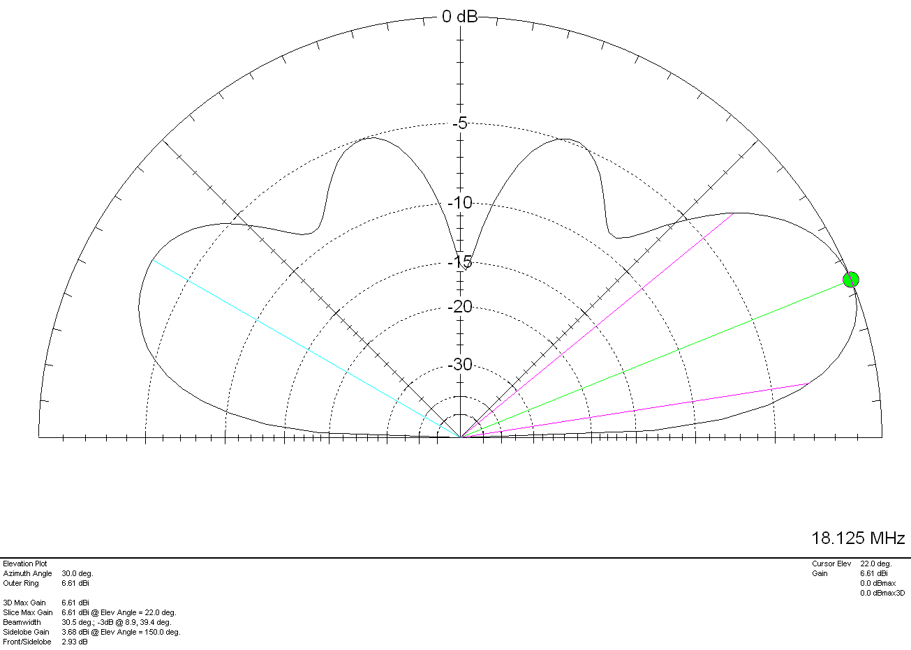
M0AWS Inverted-L Style Antenna 2D Plot on the 17m Band

With a gain of 6.61dbi (4.11dBd) at 22 degrees to the NW and NE and slightly lower gain and higher angle to the SW and SE the antenna has proven to work extremely well on the 17m band. My best DX on 17m so far has been a QSO with Eric, FK8GM in New Caledonia some 10230 miles from my QTH using just 80w of SSB.

The 15m band is a similar story, 7.6dBi (5.1dBd) at just 18 degrees pointing NW and NE. This antenna works extremely well into North America and Oceana (I’ve also worked FK8GM on 15m too). Once again there are lower gain lobes to the SW and SE at a similar angle along with some high angle radiation that aids coverage into Europe. The antenna really is a great all rounder on the 15m band.
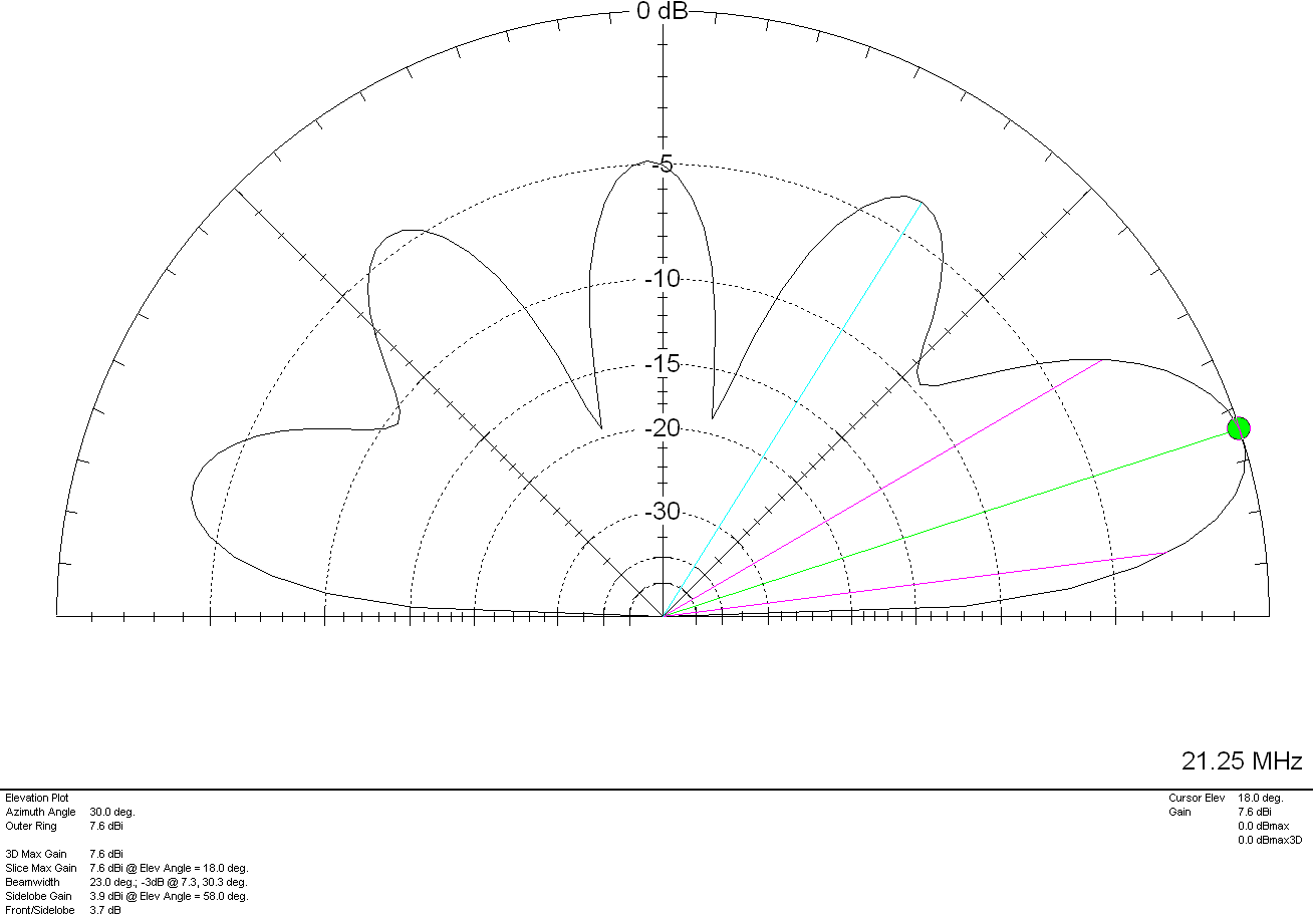
M0AWS Inverted-L Style Antenna 2D Plot on the 15m Band

The 12m and 10m bands are a similar story, low angle, high gain lobes to the NW and NE with lower gain coverage to the SW and SE.
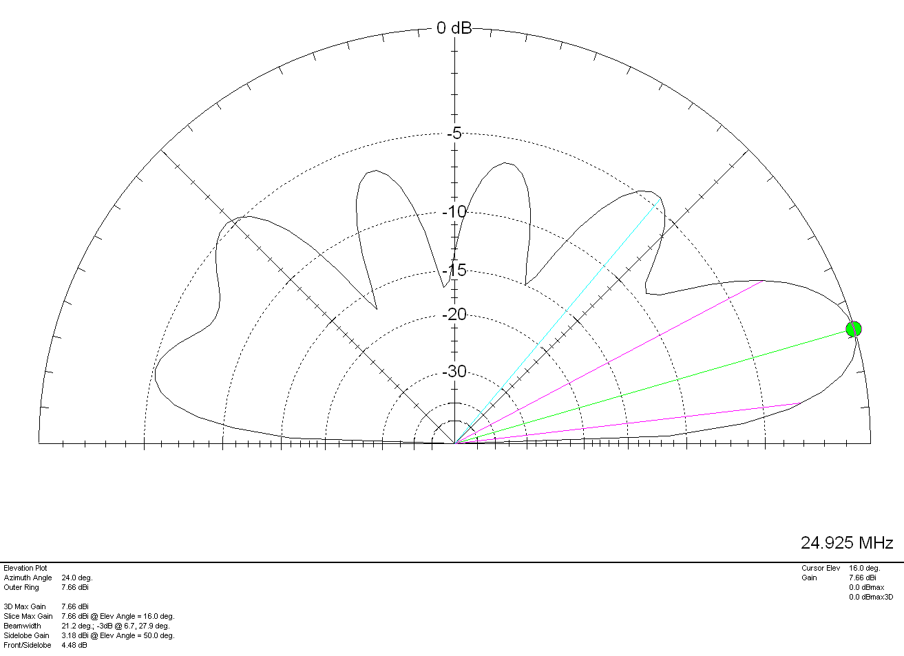
M0AWS Inverted-L Style Antenna 2D Plot on the 12m Band

On 12m the antenna has a very respectable gain of 7.66dBi (5.16dBd) at a low 16 degrees pointing NW and NE making it a great DX antenna. Once again, higher angle lower gain lobes to the SW and SE.

Finally on the 10m band the antenna has a gain of 6.96dBi (4.46dBd) at a very low angle of 14 degrees to the NW and NE. If DXing over the pole on the 10m band is your thing then this simple antenna will certainly help you along and maybe even put a smile on your face.
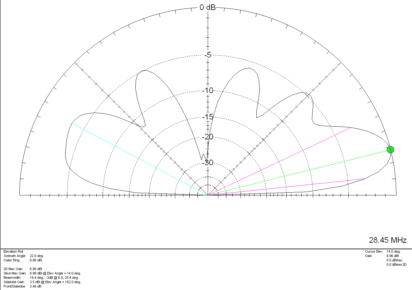
M0AWS Inverted-L Style Antenna 2D Plot on the 10m Band

For such a simple antenna that will fit easily into many typical UK gardens I have been extremely pleased with it’s performance. Whether I’m gassing on the low bands with friends from the Matrix rooms or chasing DX on the higher bands, the antenna has put a smile on my face time and time again.

On receive the antenna is surprisingly quiet, with an S3-4 background noise on the 80/60/40m bands through to less than 1 S point of noise on the higher bands. Picking out the weak DX stations really isn’t a problem.

It just goes to show that you don’t need to spend a fortune on commercial antennas to work the world on the HF bands. With as little as 80w of SSB and a piece of wire connected to a remote ATU you can have just as much fun as the big boys!

More soon …
Building MB7IBW 2m AllStarLink Internet Gateway

I’ve recently built another AllStarLink node to compliment my personal 70cm band SHARI node as I thought since I have a full duplex dual band handheld it would be great to have another node that I could connect to FreeStar or HUBNet at the same time as monitoring the Matrix node.

Rather than build another personal node I decided this time I would build a public node, obtain a callsign from the RSGB and make it available to the HAM’s locally on the 2m band.

This would make it possible for me to monitor both nodes at the same time using my Wouxun KG-UV9K full duplex dual band handheld whilst providing the local HAM community with access to the AllStarLink network.

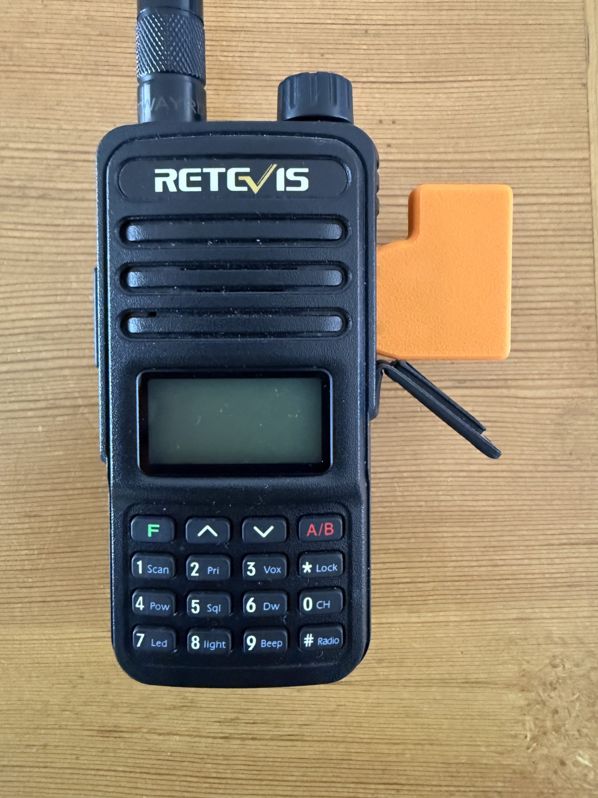
Initially I thought I may be able to use my old Retevis RT85 handheld and AIOC board for the 2m node but, after a little testing it soon became apparent that it overheats during long overs (which are common on AllStarLink) and so, I needed to find another solution.

AIOC connected to the Retevis RT85.

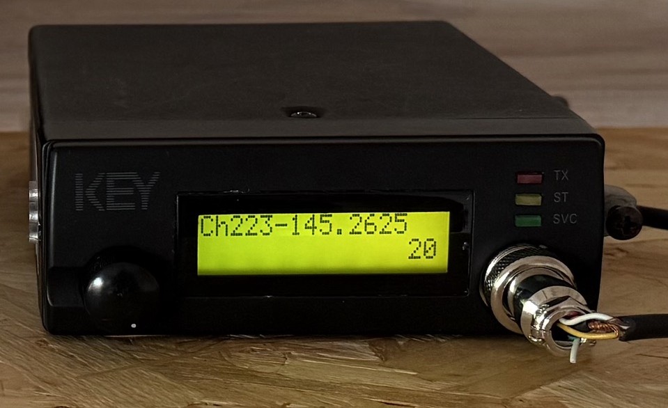
Chatting about this in the main Matrix HAM Radio room Steve, M0XVT sent me a message saying he had an old Key KM-4000 converted PMR radio that had been reprogrammed for the 2m band that he was looking to sell and that it might be ideal for the new node. Wasting no time, we came to an agreement and I was soon the proud owner of a converted PMR transceiver.

Key KM4000 2m Band PMR Radio

The KM4000 transceiver has a standard output of 15w, 10w more than I needed for the gateway and so I had to reduce the output. A quick search on the internet and I found the Thames Valley Repeater Group website that had all the information required to turn down the output.

I also had to reprogramme channel 1 to the frequency and CTCSS tone allocated to me by the RSGB so that in the event of a power outage when the radio came back on it automatically jumps to channel 1 which would be correctly setup for operation.

Unfortunately the software for programming the radio is only available for windows and so I had to build a virtual machine running windows 10 to be able to reprogramme the radio.

Once this was done I rewired the AIOC USB audio device to work with the KM4000 radio and built the AllStarLink node on a spare RaspberryPi 4.

For an antenna I made a simple end fed vertical dipole from some RG58 coax and mounted it 8m up on one of my Spiderpoles in the garden. Running a coax feed out to the antenna I did some tests into the Parrot to get the audio levels setup and checked that the DTMF codes were interpreted correctly and that the node switched connections without error.

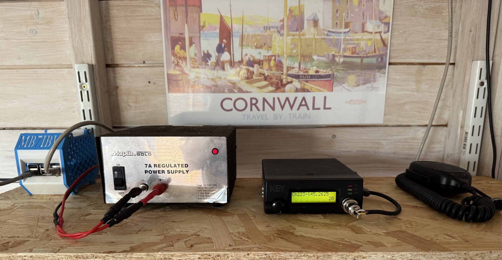
MB7IBW Internet Gateway hardware at the M0AWS QTH

Once this was done I had a few test conversations with stations on the Matrix node and FreeStar to ensure all was fine and then set the gateway status to “Operational” on the RSGB website.

This worked fine for a while with myself and some local stations using the node regularly but, then the hot weather arrived and things started to overheat. The transceiver was getting incredibly hot in the 30c+ summer temperatures and the power supply was also running extremely hot and so I decided to add some cooling.

Cooling the PSU was simple, it has a perforated top panel to which I strapped a cooling fan. This worked great and brought the temperature of the PSU down considerably.

The radio wasn’t so easy to cool. It has a solid case cover top and bottom and so cooling wasn’t going to be a simple affair.

I decided to remove the covers and drill some holes into them to allow airflow through the unit and strapped a fan to the top cover to pull the hot air out. This worked well however, on both transmit and receive I now had a warbling sound on the audio that was caused by the motor of the fan when powered up.

I found that lifting the fan up away from the case of the radio the warbling audio disappeared and things were back to normal and so, I decided to design a cooling tube to fit to the top of the radio to allow full airflow from the fan but, with the fan raised up away from the radio to resolve the audio problem.

Jumping into my CAD software I quickly designed a cooling tower to fit on the top of the radio that would allow the fan to sit far enough away from the radio so as to not affect the audio whilst at the same time pulling the hot air out of the radio and drawing cooler air in through the bottom of the case.

I sent the design through to my Bambu Lab A1 Combo 3D printer and set the print job running.

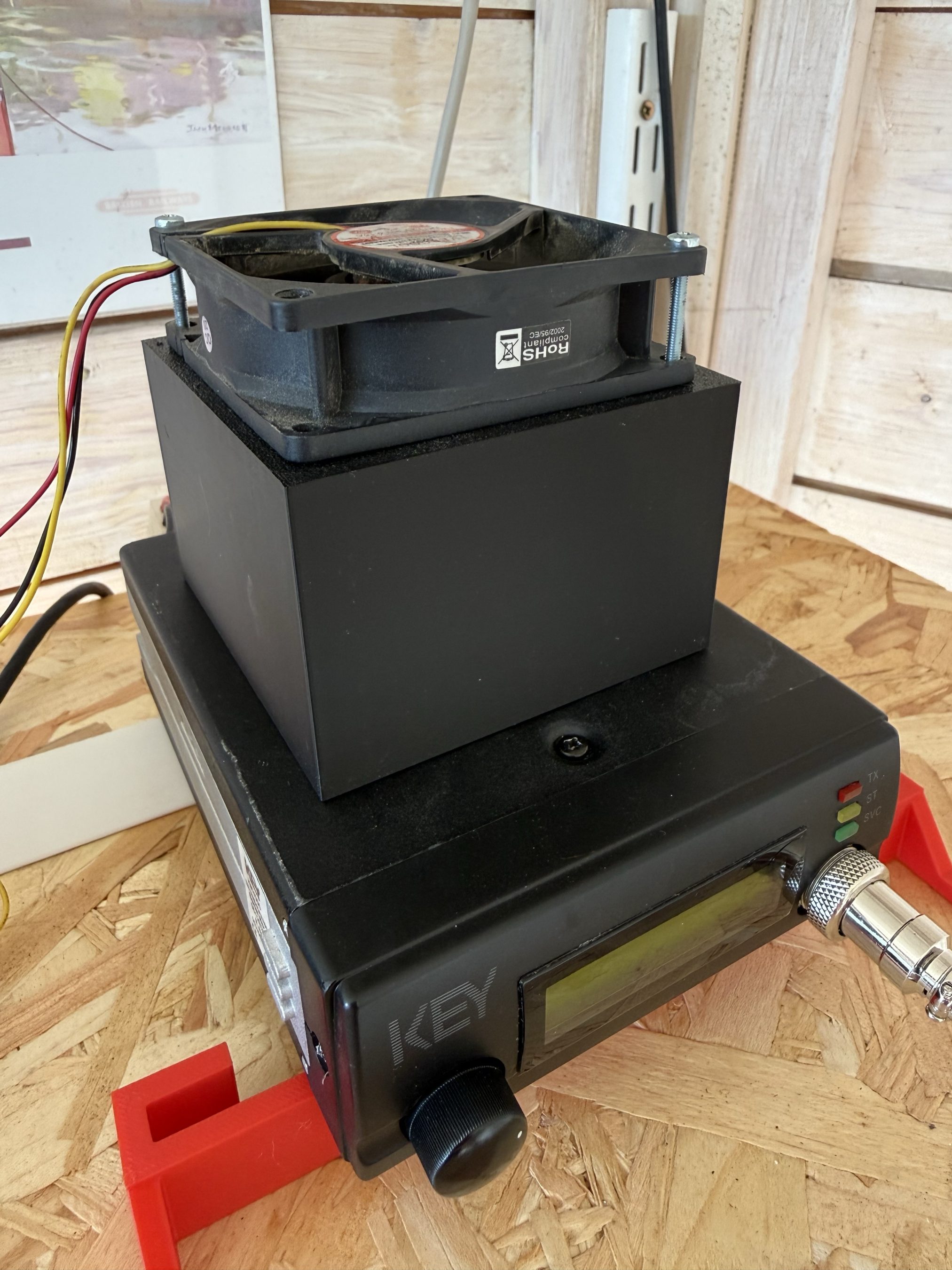
Key KM4000 Cooler
Key KM4000 Cooler

The cooler worked great with the radio staying cool to the touch and no longer overheating and reducing O/P power.

It’s amazing how much dust and dirt is in the air from all the farming activities going on at the end of our garden and how much of it is sucked in by the cooling fan. Regular cleaning is a must!

The MB7IBW Internet Gateway has been on air since mid June 2026 and has worked well. It spends most of its time connected to either FreeStar or HUBNet with connections to the Matrix Node when we have our nets.

Details on Frequency, CTCSS etc can be found under the MB7IBW menu above.

Sadly the initial interest from local HAMs has now wained and I am mostly the only user of the gateway. I was hoping more people would use it and bring some life to the 2m band, I guess time will tell.

It’s been a fun project and was interesting to go through the callsign allocation process with the RSGB representative. It was much easier than I thought it would be.

I now have all the parts to build another Internet Gateway for the 4m band. Hopefully that may attract some more interest. It’s certainly worth a try!

More soon …

More 868Mhz Antenna Tests

After initially finding that I couldn’t tune the 868Mhz ground plane antenna with the radials bent down at 45 degrees I decided to experiment to find out why.

Initially I had the radials connected to the 4 corners of the base of the chassis mount N Type socket. This works great if you have the radials completely horizontal and gives an SWR of 1.1:1 but, with the radials bent down at 45 degrees the best SWR is around 2:1.

M0AWS 868Mhz Ground Plane Antenna Close Up

Removing the radials from the base of the N Type chassis socket and soldering them to the outer of the N Type plug at the same level as the feed point for the radiating element I found that an almost perfect SWR can be achieved very easily.

M0AWS 686Mhz Antenna with radials soldered to the N Type Plug
M0AWS 868Mhz Antenna with radials soldered to the N Type Plug

It seemed weird to me that such a small change could have such a big effect on the obtainable SWR for the antenna but, as can be seen in the image below with the radials soldered to the N Type plug and bent downwards I immediately got an SWR of 1.07:1 and a much wider SWR curve.

M0AWS 868Mhz Antenna SWR curve with radials soldered to N Type plug.

By making my own antennas I’m learning a lot about antenna design for the 800-900Mhz frequency range. Minor changes seem to have a much bigger impact than they do at much lower frequencies.

More soon …