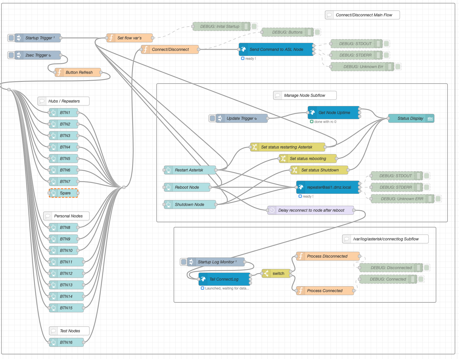
Coding of version 1 of the AllStarLink Dashboard is now complete and in the final testing phase. Below is a short video clip showing some of the functionality.
The Node-RED flow for the web app is pretty compact and easy to alter should I add more functionality in the future.
M0AWS Node-RED flow for the AllStarLink Node Dashboard
The dashboard is designed such that it’ll display nicely on mobile phones, tablets and desktop computers so, I can easily control my AllStarLink SHARI node from any of my devices around the house.
I’ll put together a more detailed article on the web app once testing is complete and it’s ready to be released into the wild.
NOTE: The info in this article is out of date and does not work with the latest version of AllStarLink. The Debian O/S it is based on is no longer in support.
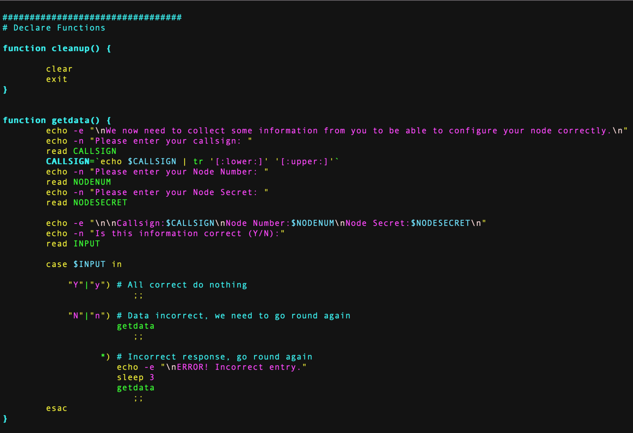
Over the last couple of days in-between doing other things I’ve been writing and testing a BASH shell script that will completely configure a fully working AllStarLink node.
M0AWS – Coding the BASH script for the automated AllStarLink installation
To use the script you must already have your RaspberryPi (preferably a Pi 3b) connected to your LAN with full internet access using the Raspbian based version of the AllStarLink software downloadable from here.
The specific version I use is:
asl-2.0.0-beta.6-kc1kcc-20210324-rpi-armhf
I have tested the BASH script using this specific version of O/S only.
Once your RaspberryPi 3b is up and running, has full internet access and is accessible on your local LAN, using SSH login in as the user ‘repeater‘ using the password ‘allstarlink‘.
It’s important you only use this login to configure the node as this is the user the script is expecting to be run by. You must login via SSH as the SHARI device needs to be connected to the RaspberryPi 3b and you won’t be able to connect a keyboard and mouse at the same time. (If you are using two USB cables for the SHARI device then you can use a keyboard and mouse along with a monitor attached to your RaspberryPi instead of using SSH).
Once logged in as user repeater run the following wget command to download the zipped install script:
You are now ready to build your AllStarLink node. Before you run the script make sure you have your node number and node secret to hand. These are obtained from the AllStarLink portal.
Once you’ve got all your node information you can run the script using the following command:
./install.sh
The script will now take you through the full process of updating the operating system as necessary, installing all the required packages and software. It will then reboot the RaspberryPi and you will need to login and run the script a second time using the command above.
On the second run the script will install some python specific software, ask you to enter your callsign, node number and node secret and will then configure your node. The last thing it does is configure the Allmon2 and Supermon Web Admin websites. During this process it will ask you to enter a password twice for the Admin user for the two websites, make sure you make a note of this password as you will need it to login and control your node.
Once the node is configured it will be rebooted and you will then be able to connect to your node using your favourite web browser and the user admin and the password you set above.
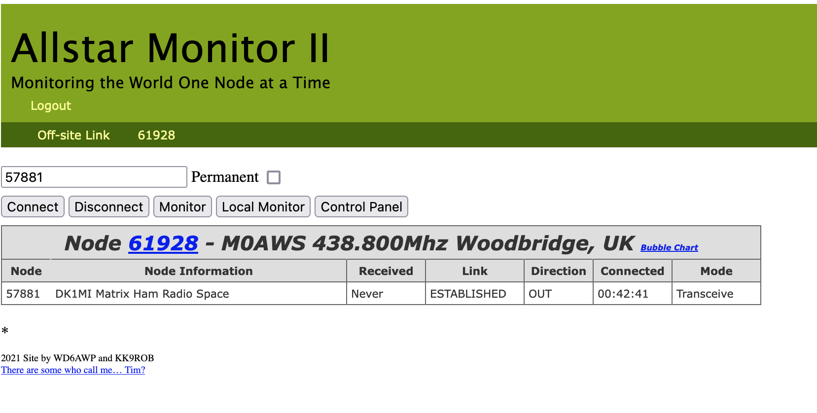
To access the Allmon2 web-admin system use the following URL:
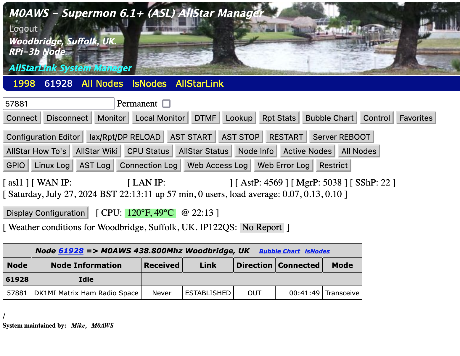
For those of you who prefer Supermon you an use the following URL:
http://your-RaspberryPi-IP-Address/supermon
M0AWS – Supermon Web Admin view
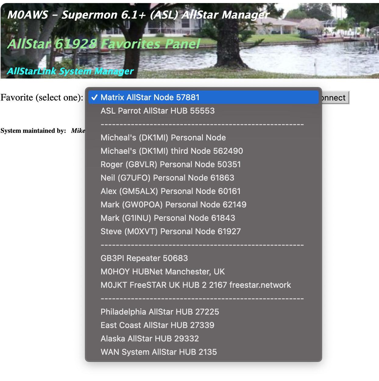
I have also pre-populated the Favorites button with a list of nodes that I use often. You can easily change these entries by editing the favorites.ini file in the /var/www/html/supermon directory as user root.
M0AWS – Supermon pre-populated Favourites drop down list
When you first login to your node via your web browser you’ll notice that it says your node isn’t in the database. You can update the database by using the following URL in your web browser:
Looking to expand the device capability I stumbled across a really interesting little project that is still in the early stages of development but, is functional and worth trying out.
The TC²-BBS Meshtastic Version is a simple BBS system that runs on a RaspberryPi, Linux PC or virtual machine (VM) and can connect to a Meshtastic device via either serial, USB or TCP/IP. Having my M0AWS-1 Meshtastic node at home connected to Wifi I decided to use a TCP/IP connection to the device from a Linux VM running the Python based TC²-BBS Meshtastic BBS.
Following the instructions on how to deploy the BBS is pretty straight forward and it was up and running in no time at all. With a little editing of the code I soon had the Python based BBS software M0AWS branded and connected to my Meshtastic node-1.
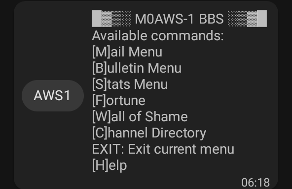
M0AWS Meshtastic BBS Main Menu accessible on M0AWS-1 node.
The BBS system is very reminiscent of the old packet BBS systems of a bygone era but, it is ideal for the Meshtastic world as the simple menus and user interface are easily transmitted in seconds via the Mesh using minimal bandwidth.
The BBS is accessible by opening a Direct Message session with the M0AWS-1 node. Sending the letter H to the node will get you the initial help screen showing the menu above and then from there onwards it’s just a matter of selecting the menu item and following the BBS prompts to use the BBS.
The BBS also works across MQTT. I tested it with Dave, G4PPN and it worked perfectly via the Meshtastic MQTT server.
This simple but, effective BBS for the Meshtastic network will add a new message store/forward capability to the Mesh and could prove to be very important to the development of the Meshtastic mesh in the UK and the rest of the world.
This solution has worked incredibly well from the outset and over time I’ve added extra functionality that I’ve found to be useful to enhance the overall setup.
The latest addition to the ground station solution is a Sennheiser Headset that I picked up for just £56 on Amazon (Much cheaper than the Heil equivalents at the HAM stores!) and have found it to be excellent. The audio quality from both the mic and the headphones is extremely good whilst being light and comfortable to wear for extended periods.
M0AWS – Sennheiser SC 165 Headset
To incorporate this into the ground station the headset is connected to my Kubuntu PC and the audio chain to the IC-705 is sent wirelessly using the latest version of WFView. This works extremely well. The receive audio comes directly from the GQRX SDR software to the headphones so that I have a full duplex headset combination.
Audio routing is done via pulse audio on the Kubuntu PC and is very easy to setup.
Since I no longer have a mic connected to the IC-705 directly I found that I needed a way to operate the PTT wirelessly and this is where the latest addition to my NodeRed QO-100 Dashboard comes in.
Adding a little functionality to the NodeRed flow I was able to create a button that toggles the IC-705 PTT state on and off giving me the ability to easily switch between receive and transmit using a simple XMLRPC node without the need for a physical PTT button.
M0AWS – Additional NodeRed PTT Flow
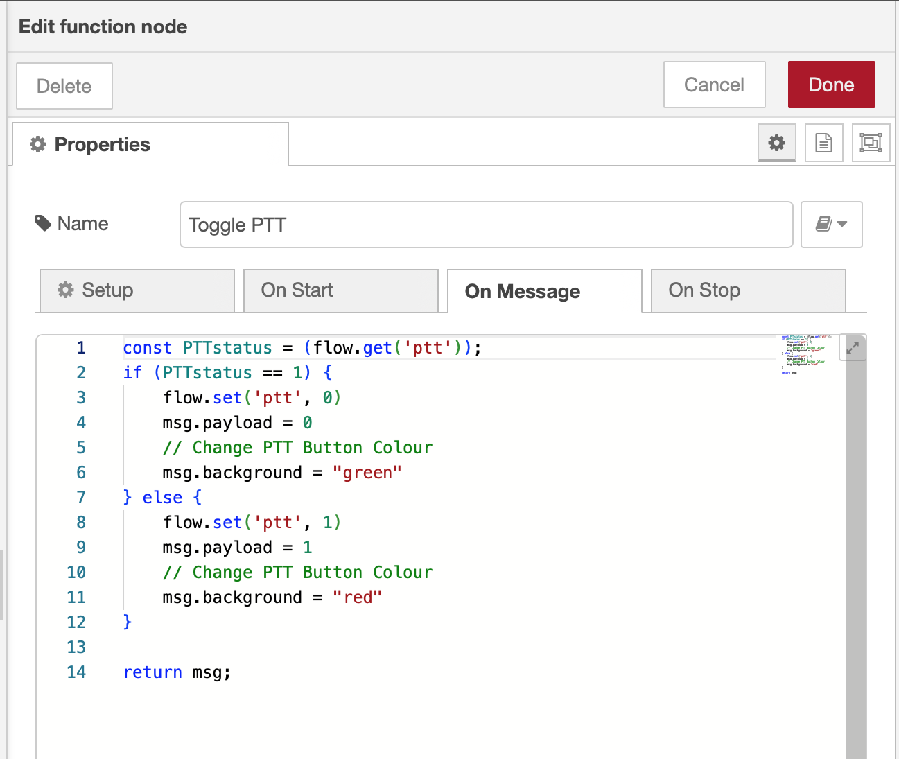
The PTT state and PTT button colour change is handled by the Toggle PTT function node shown in the above flow. The code to do this is relatively simple as shown below.
M0AWS – NodeRed Toggle PTT Function to change button colour
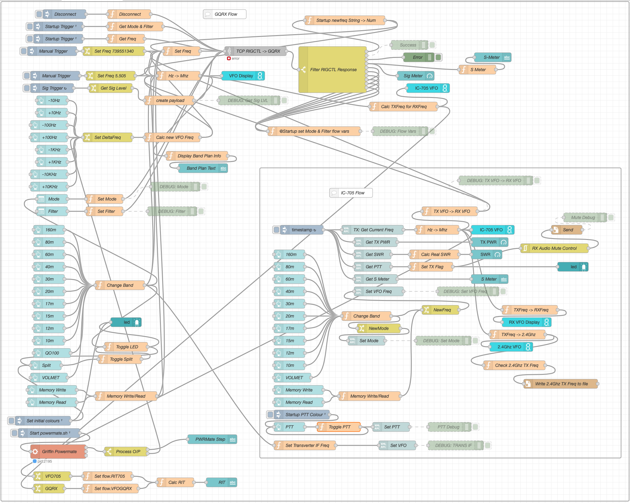
The entire QO-100 Dashboard flow has grown somewhat from it’s initial conception but, it provides all the functionality that I require to operate a full duplex station on the QO-100 satellite.
M0AWS – NodeRed QO-100 Dashboard complete flow
This simple but, effective PTT solution works great and leaves me hands free whilst talking on the satellite or the HF bands when using the IC-705. This also means that when using my IC-705 it only requires the coax to be connected, everything else is done via Wifi keeping things nice and tidy in the radio shack.
M0AWS – Updated NodeRed QO-100 Dashboard with PTT button
The image above shows the QO-100 ground station in receive cycle with the RX/TX VFO’s in split mode as the DX station was slightly off frequency to me. The PTT button goes red when in TX mode just like the split button shown above for visual reference.
As you can probably tell, I’m a huge fan of NodeRed and have put together quite a few projects using it, including my HF Bands Live Monitoring web page.
I’ve got a couple of old RaspberryPi computers on the shelf in the shack and so decided it was time for me to put one of them to good use. The first model on the shelf is the oldest and is one of the very first RaspberryPi 1 computers that was released. (It’s the one with the yellow analog video signal output on the board!). This particular model is extremely slow but, I hang onto it just as a reminder of the first SBC in the line.
The second one is a RaspberryPi 2, a quad core machine that is only slightly faster than the first model but, it’s powerful enough to run HAM Clock.
It didn’t take long to install a vanilla Raspbian Desktop O/S and get it configured on the local LAN. I installed a few packages that I like to have available on all my Linux machines and then started on the HAM Clock install.
The first thing I needed to do was install the X11 development library that is required to compile the HAM Clock binary. To do this, open a terminal and enter the command below to install the package.
sudo apt install libx11-dev
You will need to type in your password to obtain root privileges to complete the installation process and then wait for the package to be installed.
The HAM Clock source code is available from the HAM Clock Website under the Download tab in .zip format. Once downloaded unzip the file and change directory into the ESPHamClock folder ready to compile the code.
cd ~/Downloads/ESPHamClock
Once in the ESPHamClock directory you can run a command to get details on how to compile the source code.
make help
This will check your system to see what screen resolutions are available and then list out the options available to you for compiling the code as shown below.
The following targets are available (as appropriate for your system)

    hamclock-800x480          X11 GUI desktop version, AKA hamclock
    hamclock-1600x960         X11 GUI desktop version, larger, AKA hamclock-big
    hamclock-2400x1440        X11 GUI desktop version, larger yet
    hamclock-3200x1920        X11 GUI desktop version, huge

    hamclock-web-800x480      web server only (no display)
    hamclock-web-1600x960     web server only (no display), larger
    hamclock-web-2400x1440    web server only (no display), larger yet
    hamclock-web-3200x1920    web server only (no display), huge

    hamclock-fb0-800x480      RPi stand-alone /dev/fb0, AKA hamclock-fb0-small
    hamclock-fb0-1600x960     RPi stand-alone /dev/fb0, larger, AKA hamclock-fb0
    hamclock-fb0-2400x1440    RPi stand-alone /dev/fb0, larger yet
    hamclock-fb0-3200x1920    RPi stand-alone /dev/fb0, huge
For my system 1600×960 was the best option and so I compiled the code using the command as follows.
make hamclock-1600x960
It’s no surprise that it takes a while to compile the code on such a low powered device. I can’t tell you how long exactly as I went and made a brew and did a few other things whilst it was running but, it took a while!
Once the compilation was complete you then need to install the application to your desktop environment and move the binary to the correct directory.
make install
Once the install is complete there should be an icon on the GUI desktop to start the app. If like mine it didn’t create the icon then you can start the HAM Clock by using the following command in the terminal.
/usr/local/bin/hamclock &
The first time you start the app you’ll need to enter your station information, callsign, location etc and then select the settings you want to use. There are 4 pages of options for configuring the app all of which are described in the user documentation.
M0AWS – HAM Clock running on RaspberryPi Computer
Once the configuration is complete the map will populate with the default panels and data. I tailored my panels to show the items of interest to me namely, POTA, SOTA, International Beacon Project and the ISS space station track. I was hoping to be able to display more than one satellite at a time on the map however, the interface only allows for one bird to be tracked at a time.
You can access the HAM Clock from another computer using a web browser pointed at your RaspberryPi on your local LAN using either the IP address or the hostname of the device.
http://<hostname>:8081/live.html

or

http://<ip-address>:8081/live.html
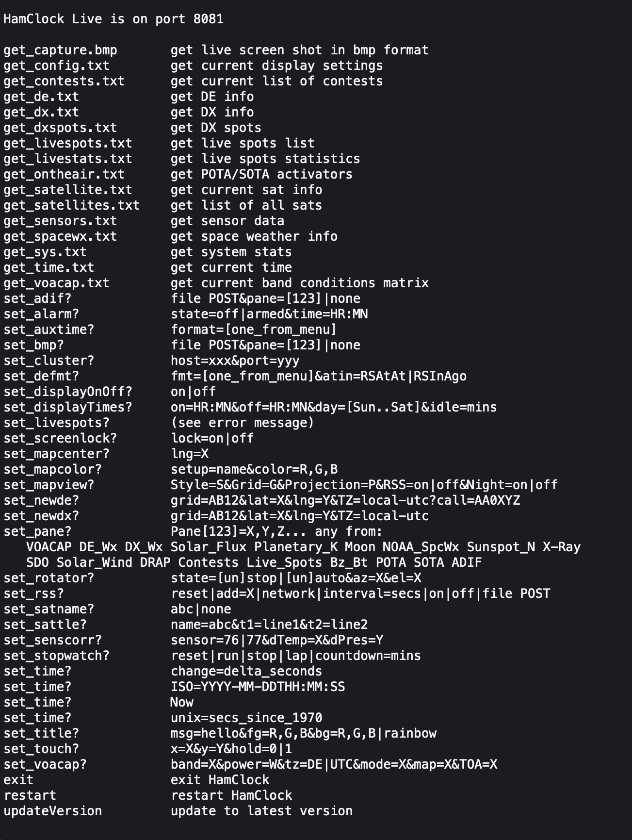
You can also control the HAM Clock remotely via web browser using a set of web commands that are detailed on port 8080 of the device.
http://<hostname or ip-address>:8080/
M0AWS – HAM Clock remote command set
This is a great addition to any HAM shack especially if, like me you have an old HDTV on the wall of the shack that is crying out to display something useful.
More soon …
We use cookies to ensure that we give you the best experience on our website. If you continue to use this site we will assume that you are happy with it.