I’ve not been on the radio much over the last few weeks as I’ve had my head down other radio related rabbit holes.
One of the rabbit holes is a Node-Red project to make my online logs a little more interactive. For sometime now my logs have been displayed on my website as nicely formatted, searchable HTML pages however, they don’t really allow the viewer (myself included) to see the global coverage of all the contacts so, I decided to write a Node-Red flow that would do just that.
M0AWS Interactive Log Flow
The flow itself isn’t too complicated and basically consists of reading in the individual ADIF formatted log files, processing the data and then sending the data in the correct format to the map node for display.
I’ve had to write a few functions to handle the processing of the ADIF formatted data but, these aren’t particularly complex and are fairly easy to understand even if like me, you’re not a Javascript programmer.
The flow is working perfectly however, I’m in the process of reworking the format generic payload function to reduce the amount of code and make it more efficient.
M0AWS SSB / CW / FreeDV Interactive Log World Map
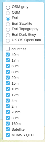
M0AWS Interactive Log Map Layers Menu
The flow generates two maps, one for voice / CW /Satellite contacts and the other for WSJT-X FT4/8 contacts. Every pin on the map is colour coded by band with satellite contacts being denoted by a satellite icon.
Each pin / icon on the map is clickable and reveals the data of the QSO being displayed.
In the top right-hand corner of the map there is a drop down layermenu that allows the viewer to filter by band thus reducing the number of icons on the screen at any one time.
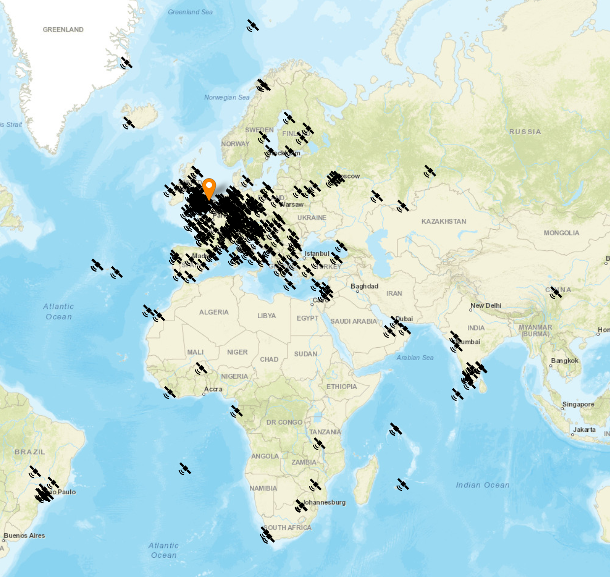
Seeing the data presented on a map really brings my logs alive. An example of this is that I had no idea I’d worked so many stations in India on the QO-100 Satellite.
The small icons in the pins show a microphone for SSB/FM/FreeDV contacts and a downwards pointing triangle in a box for CW contacts. Sadly I couldn’t find a Morse key icon in the collection available.
M0AWS filtered view of QO-100 Satellite contacts
I only use FT4/8 for testing new antenna designs however, it’s interesting to see the global coverage accomplished with this weak signal mode.
M0AWS WSJT-X FT4/8 Interactive Log World Map
Once I’ve finished rewriting the format generic payload function I will make the flow available for download here so that others can also create an interactive view of their radio logs.
If you want to have a look at the maps and try them out for yourself, they are available under the Logs menu above.
This Node-Red instance is running in a virtual machine (VM) on a 16GB RAM RaspberryPi 5 that is also running a number of other VMs at the same time so, it’s safe to say it’s not heavy on CPU and will run on the older Pi4 as well.
For sometime I’ve been using PiHPSDR software to drive my Hermes Lite 2 (HL2) SDR transceiver. It’s a great piece of OpenSource software for SDR transceivers and has the best documentation that I have ever seen from an OpenSource project.
I must admit, I’ve had to make a few changes to get the software how I like it but, that’s the great thing about OpenSource software, you get the source code and can do what you like to it.
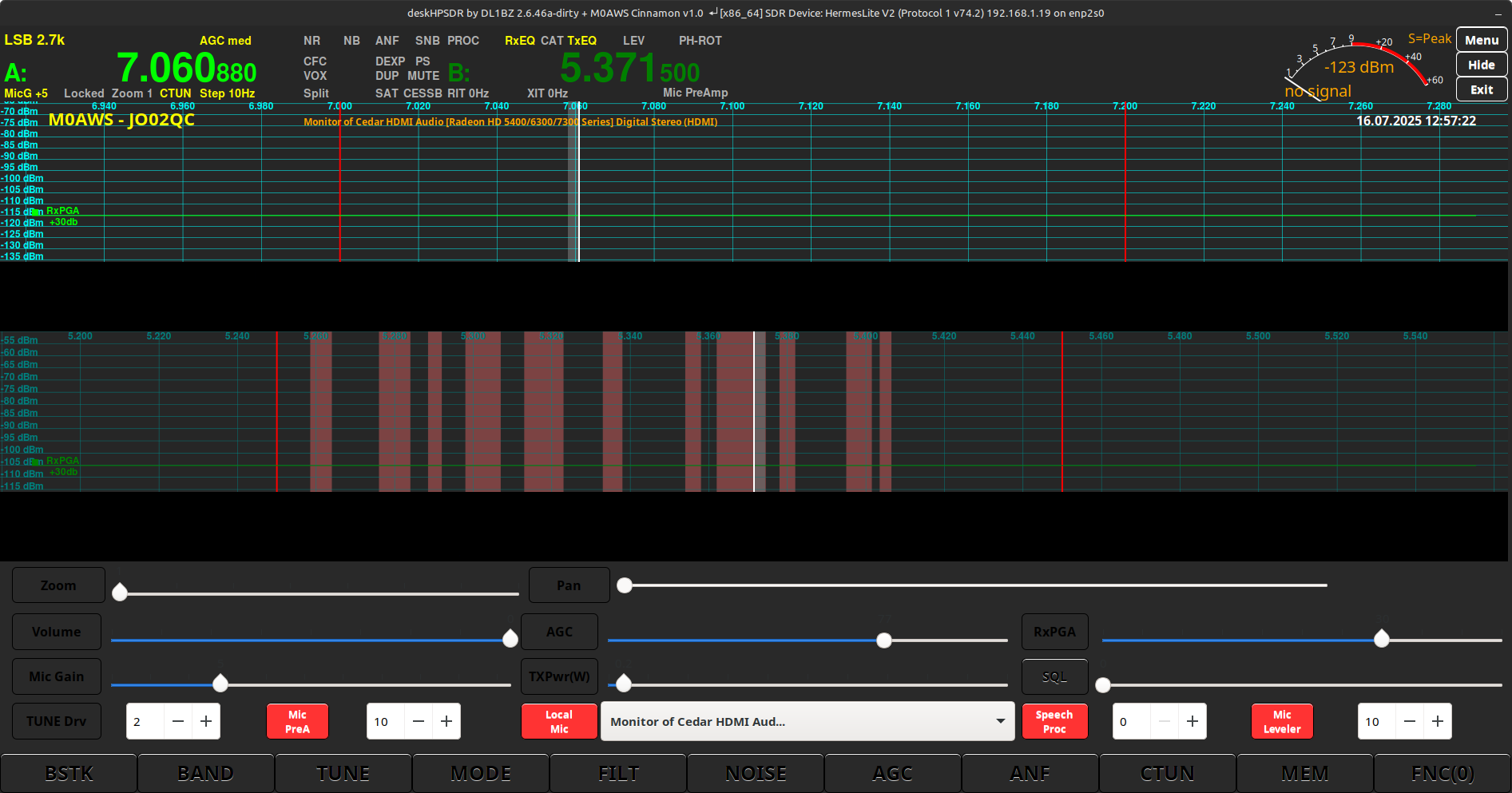
Following in this thread I recently decided to give DeskHPSDR a try. DeskHPSDR is a fork of the original PiHPSDR but, with some changes mainly aimed at larger display computers.
After compiling DeskHPSDR on my Kubuntu Linux PC in the radio shack, I found there were a few issues, mainly the colours were hard on the eyes and band/channel markers wrong/missing on a few of bands.
DeskHPSDR default colour scheme on Kubuntu 22.04LTS (KDE-Plasma)
I decided to dive in and take a look at the source code and try and sort out the colour issues as blue writing on dark buttons made them almost impossible to read under a KDE-Plasma desktop.
Delving through the appearance.c and css.c files I found that there were many changes required to get the end result I wanted. The biggest pain is that you have to recompile the source code after each change to see if the code change had worked, this results in many recompiles, a tedious task.
After spending many hours making changes I decided to email Heiko, DL1BZ who is the developer of DeskHPSDR. Over a number of emails we discussed getting the colour management code changed such that it was read in at start time from a separate css file rather than having to be compiled into the main program.
After a few emails back and forth, Heiko changed the code so that a separate CSS file could be read in at start up instead of the hard coded CSS in the C code files, this worked great and made it much easier to make colour changes without constant compilations of the code.
Next I needed to edit the bands.c file to change some of the band edge markers to show the UK band plan as, by default they are incorrect even though I have the region set to UK.
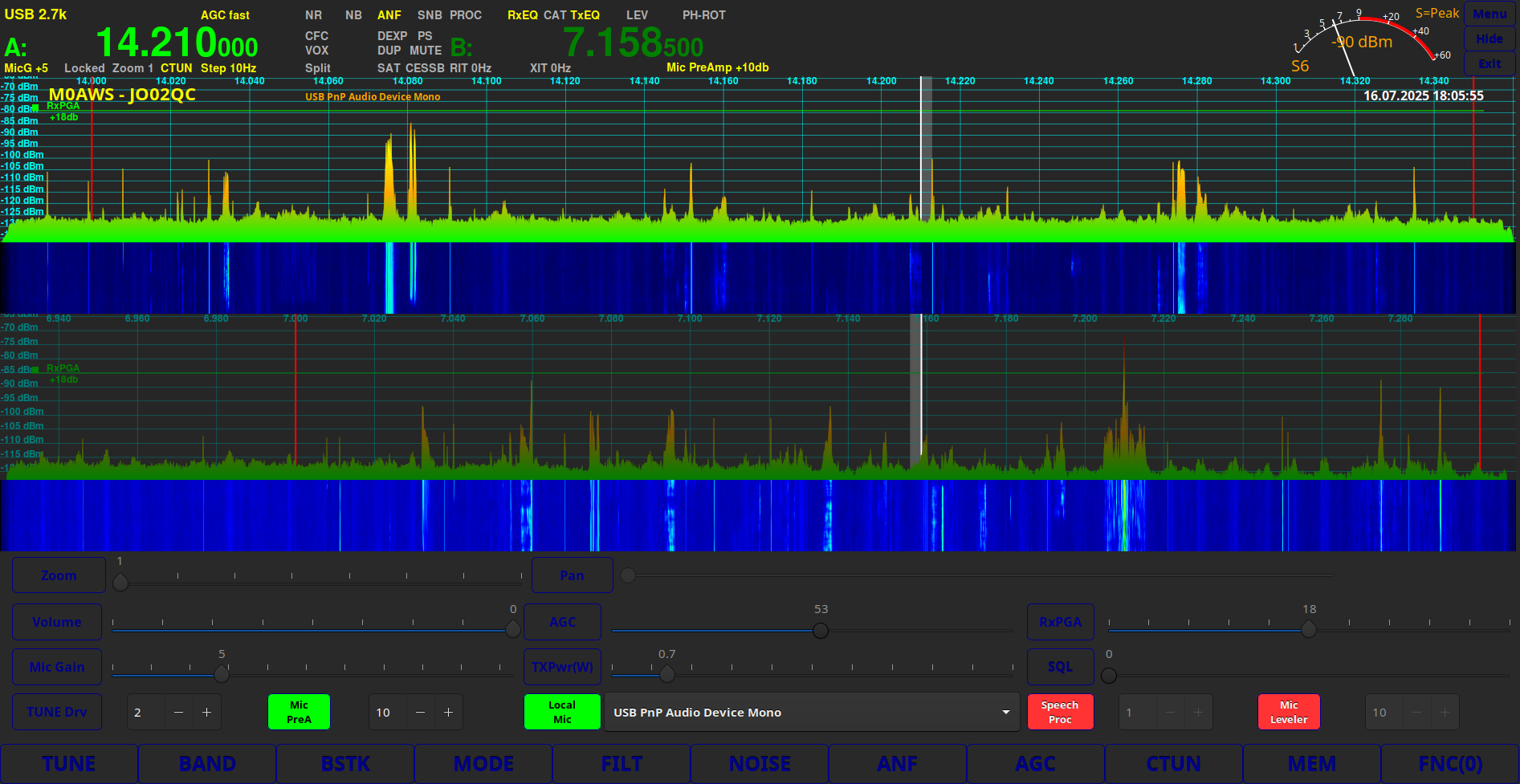
Editing the appearance.c file once more I was able to change the colour of the rather bright green panadapter signal display to a much more pleasing blue fading to red as the signal gets stronger.
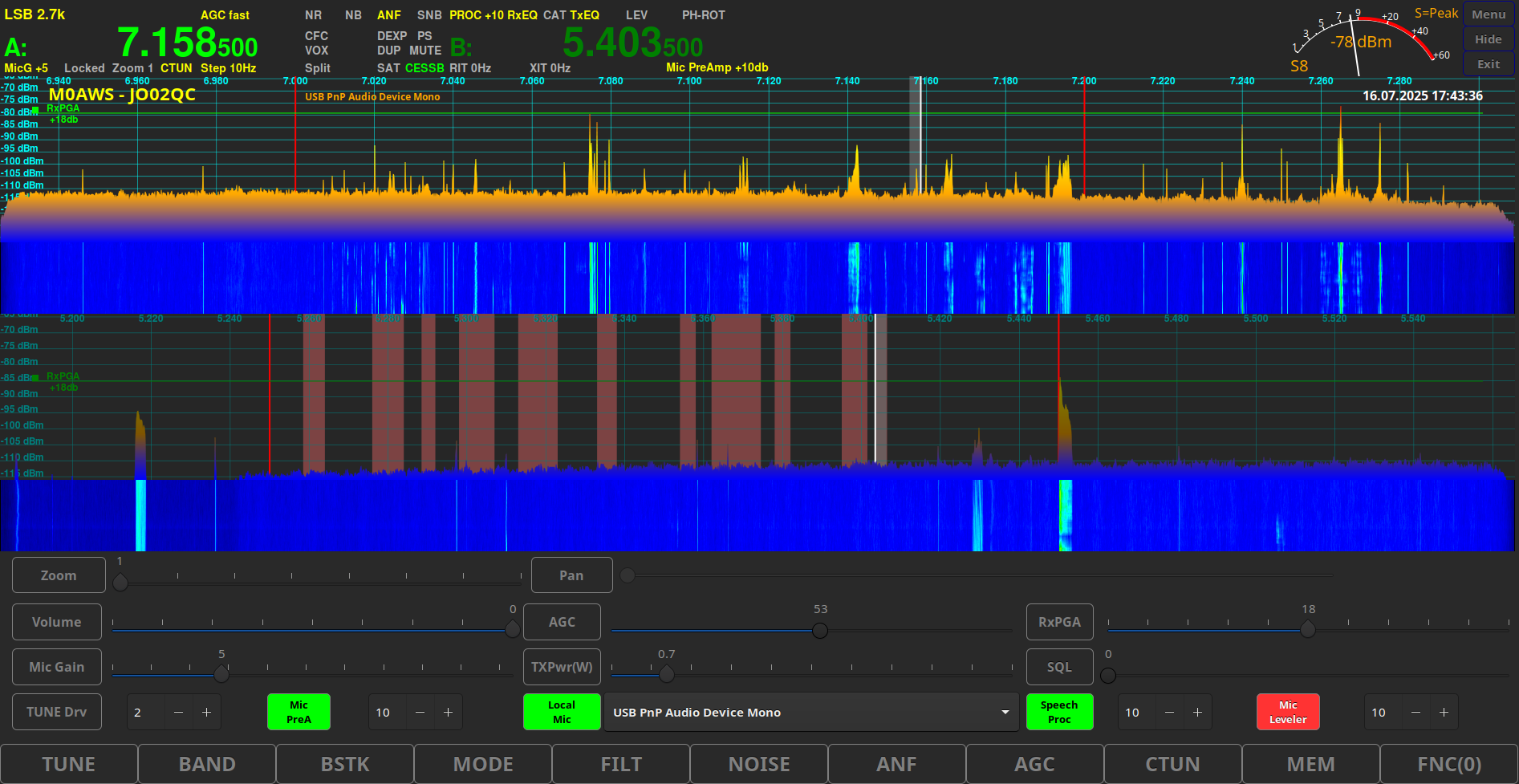
One thing I really like about PiHPSDR was the channel markers on the 60m band. Anyone that uses the 60m band will know that the UK allocation is split into 11 different channels separated by spaces used by the primary user of the band. The channel markers make it just that bit easier to ensure you don’t stray out of the allocated channels however, this code had been removed from DeskHPSDR as Heiko didn’t consider it necessary.
Once again I pinged an email over to Heiko explaining how useful it is to UK HAMs and he very kindly put the code back into DeskHPSDR so that the 60m channels are once more clearly visible on the panadapter.
DeskHPSDR modified colour scheme on Kubuntu 22.04LTS (KDE-Plasma)
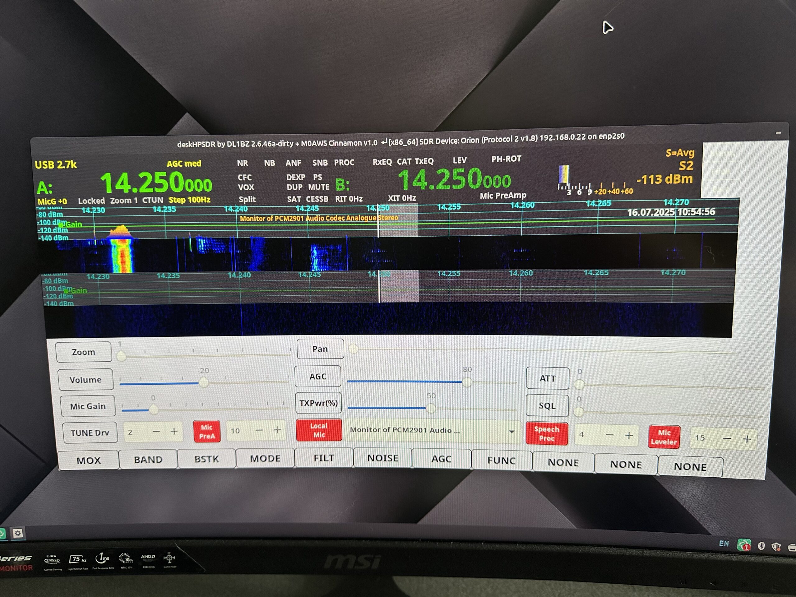
Feeling happy with the new colour configuration I decided to test it out on Linuxmint Cinnamon. Sadly the scheme that looked so nice under Kubuntu 22.04LTS didn’t look the same under Linuxmint and so I had to set about coming up with a version of the CSS file for this platform too.
After quite a few hours tinkering with CSS code I found it to be impossible to get the colour scheme on Linuxmint Cinnamon Edition identical to that I’d created under Kubuntu KDE-Plasma so, I settled for a look that was as close as possible.
DeskHPSDR on Linuxmint Cinnamon Edition with colour modifications.
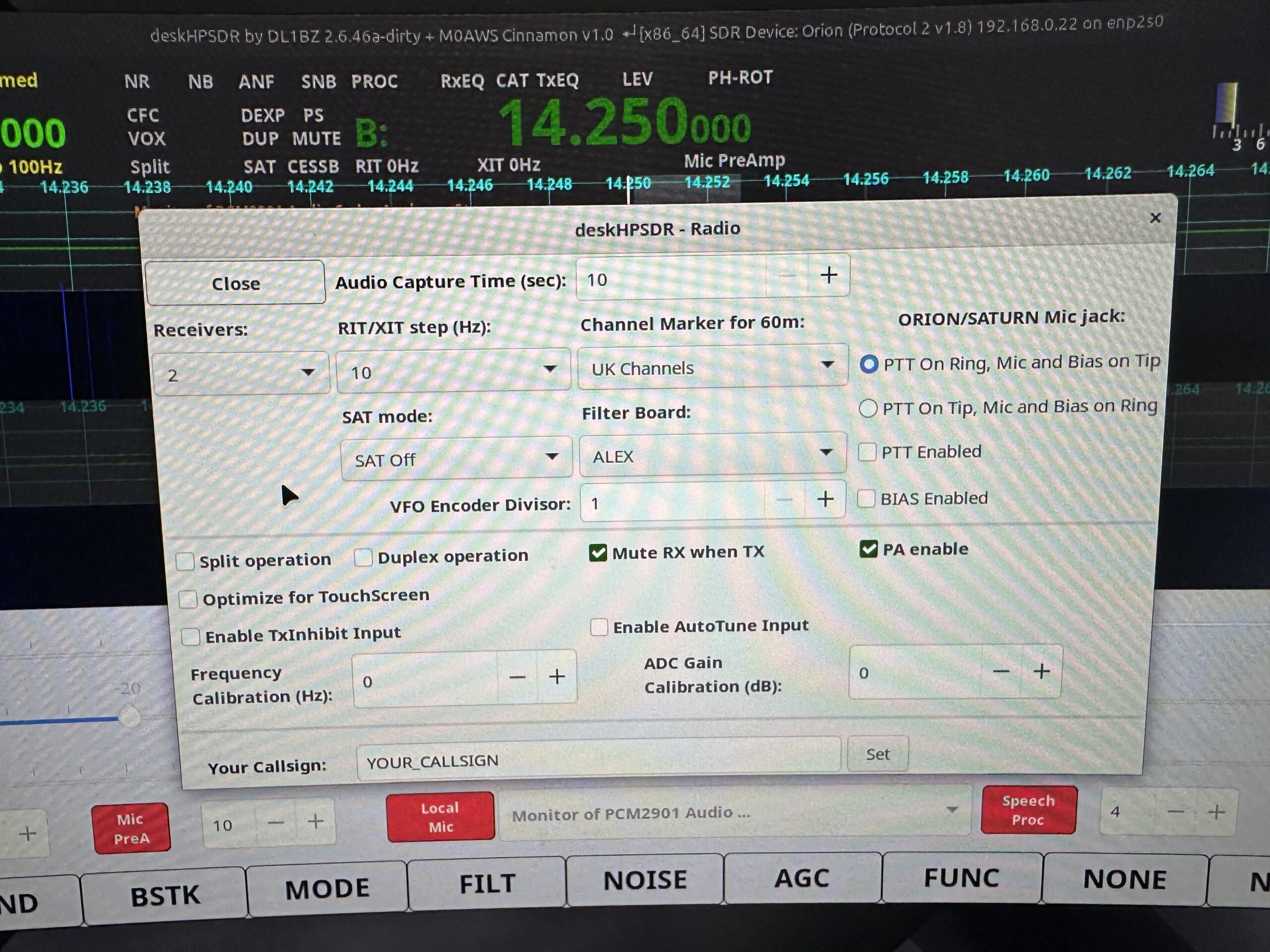
Chatting with Steve, M0XVT we thought it would be a good idea to test it on his Kubuntu Linux and Linuxmint PCs. He is using a later version of Kubuntu than I am (24.04LTS) and so, it would be a good test to see if the colour scheme looked the same.
Sadly it turns out that for some bizarre reason the colours come out different in the later version of Kubuntu. This is a real nuisance as it means we’d need a separate colour scheme defining for each version of the O/S. Perhaps using CSS isn’t the best way to define a colour scheme in applications.
For some very strange reason the colours were also rendered differently on his Linuxmint PC even though he was using the same version of the O/S as I am.
DeskHPSDR running on Kubuntu 24.04LTS with colour scheme not rendering correctly
Another issue was found whilst testing on Steve’s computers which seems to be caused by the fact he uses an Anan 200D SDR.
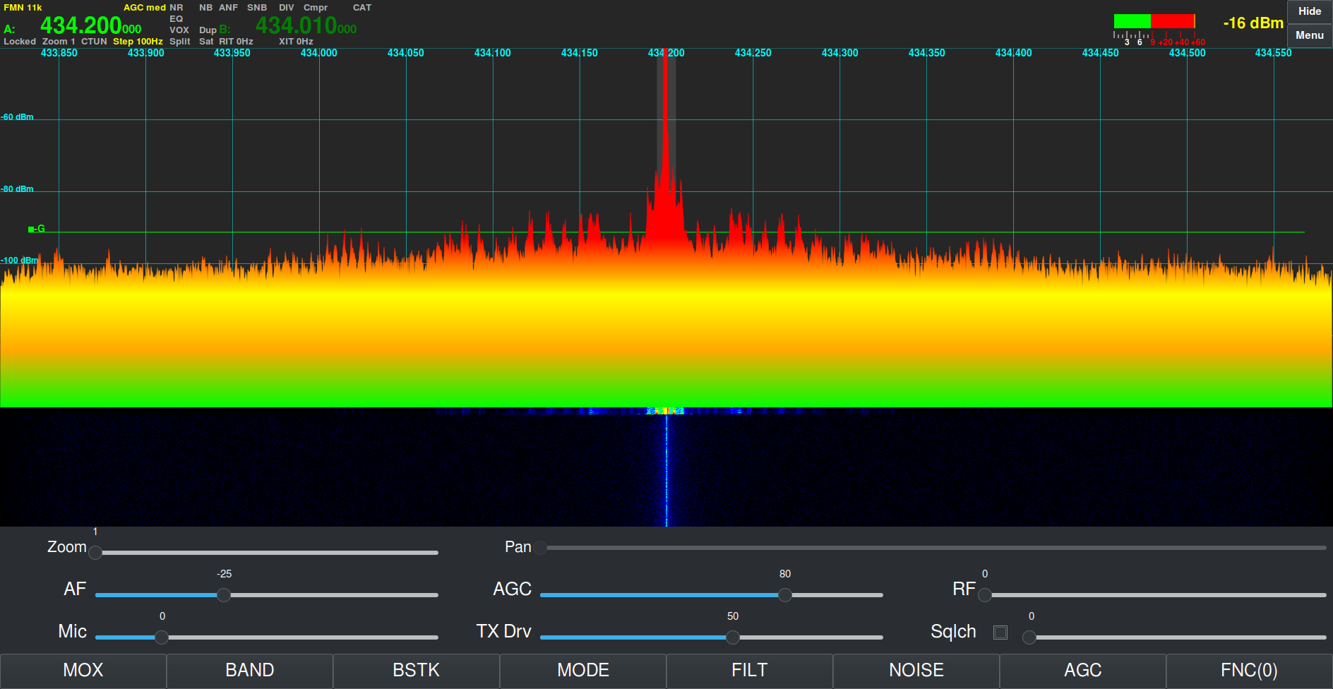
Looking at the documentation on github in theory DeskHPSDR should support the Anan range of SDR transceivers however, we found that it’s impossible to select the sample rate as the drop down selection list is completely missing from the Radio menu with the radio defaulting to its lowest sample rate of 48k resulting in not being able to see the full spectrum of frequency ranges on the bands.
DeskHPSDR Sample Rate drop down missing when using an Anan SDR
The other thing to note is that the Remote Server functionality has also been removed from the code by Heiko as he feels it’s not necessary. This may be a deal breaker for some and so they may choose not to use DeskHPSDR and to continue using PiHPSDR instead.
I will at some point make the O/S specific CSS files and source code available for download for those that want to use DeskHPSDR with my colour scheme changes.
I’m not sure at the moment whether I will continue using DeskHPSDR or go back to PiHPSDR, time will tell.
As I detailed in my QO-100 Satellite Ground Station Complete Build article I use a Griffin Powermate VFO knob to control the receive VFO frequency when in split mode or needing to RIT a DX station to get on frequency with them. Since building the ground station this setup has worked perfectly and without error however, for the last couple of days every time I start my Kubuntu Linux PC the USB VFO knob appears on a different USB event queue.
For the last two years the VFO knob has always appeared on /dev/input/event11 but, after connecting a Pluto+ SDR transceiver to the PC via USB the VFO knob now appears randomly on the /dev/input/events tree. This normally doesn’t cause any problems but, my Node-Red QO-100 Ground Station Control Dashboard expects the device to always be on /dev/input/event11.
Griffin Technology Powermate VFO
Initially I tried to find a way to lock the USB VFO knob to /dev/input/event11 however, there doesn’t appear to be a way to do this as the event tree is built at boot time by udev.
Digging deeper into udev I discovered that it’s possible to create a udev rule that is read at boot time, that will search for the device and then create a symlink to it with the same name each time making the USB VFO Knob appear as if it’s always in the same place. This is exactly what I need so I set about writing the udev rule.
To find out what event the USB VFO knob is currently on I ran evtest on the Linux command-line and got the following output.
No device specified, trying to scan all of /dev/input/event*
Available devices:
/dev/input/event0:      Sleep Button
/dev/input/event1:      Power Button
/dev/input/event2:      Power Button
/dev/input/event3:      Video Bus
/dev/input/event4:      Telink Wireless Receiver Mouse
/dev/input/event5:      Telink Wireless Receiver Consumer Control
/dev/input/event6:      Telink Wireless Receiver System Control
/dev/input/event7:      Telink Wireless Receiver
/dev/input/event8:      Kensington USB/PS2 Orbit
/dev/input/event9:      PixArt USB Optical Mouse
/dev/input/event10:     USB PnP Audio Device
/dev/input/event11:     HDA Intel PCH Front Mic
/dev/input/event12:     HDA Intel PCH Rear Mic
/dev/input/event13:     HDA Intel PCH Line
/dev/input/event14:     HDA Intel PCH Line Out Front
/dev/input/event15:     HDA Intel PCH Line Out Surround
/dev/input/event16:     HDA Intel PCH Line Out CLFE
/dev/input/event17:     HDA Intel PCH Line Out Side
/dev/input/event18:     HDA Intel PCH Front Headphone
/dev/input/event19:     HDA Intel PCH HDMI/DP,pcm=3
/dev/input/event20:     HDA Intel PCH HDMI/DP,pcm=7
/dev/input/event21:     HDA Intel PCH HDMI/DP,pcm=8
/dev/input/event22:     HDA Intel PCH HDMI/DP,pcm=9
/dev/input/event23:     HDA Intel PCH HDMI/DP,pcm=10
/dev/input/event24:     Griffin PowerMate
/dev/input/event25:     Realtek RTL2832U reference design
This shows that currently the Griffin Powermate VFO knob is on event 24.
Having this information I now needed to use the udevadm command to obtain the Vendor and Product ID of the USB VFO knob.
udevadm info -a /dev/input/event24
This returns a lot of information about the USB device, more than I was expecting but, upon close inspection I found the Vendor and Product IDs.
Note: That should all be on one line in the file not wrapped as shown above.
This one line rule sets the subsystem to input events, sets the Product and Vendor IDs to that of the Griffin Powermate USB VFO knob and then creates the symlink /dev/powermate
Once I’d completed the rule, I saved the file and exited the vi text editor.
Next I needed to use udevadm to get it to re-read the udev rules as if it were boot time and check that it created the symlink.
udevadm control -R
Once the udevadm command completed I used the ls command to see if the symlink had been created.
As shown above the symlink had been created and I could now enter /dev/powermate into my Node-Red code so that it always finds the VFO knob regardless of what event number it appears on.
Just to make sure it worked correctly at boot time, I shutdown my Kubuntu linux PC and started it from a cold boot. Sure enough the /dev/powermate symlink was created and pointed to the new event number in the /dev/input tree, problem solved!
I hope this information is useful to Linux users especially as it can be used for any USB input device.
It’s worth noting that you will need to be root user to run most of the commands or use sudo from your regular user account.
I’ve not written an article on the blog for a while now mainly because I’ve not had anything interesting to write about.
Today that changed, as I had a fun little project to dive into.
Steve, M0XVT sent me his Pluto+ SDR transceiver after his rather unsuccessful attempt at updating the firmware. Long story short, he somehow managed to brick the Pluto+ rendering it completely useless.
Not having a Pluto+ myself I’ve never actually played with one before and so this was new and exciting. I have, however played with Steve’s LibreSDR which is a later iteration of the Pluto+ and so, I had an idea of what I was getting into.
Firstly, how do you know when you have bricked your Pluto+?
Fortunately the Pluto+ device is actually quite clever and will inform you when it is bricked. The first sign you will notice is that you can no longer connect to the device using a USB connection to the data socket. The second sign is that when you take the top off the case you’ll notice that the blue LED is off and the green LED is on constantly. These are both classic signs that the device is bricked and needs rescuing
So, how do we rescue a bricked Pluto+?
Firstly, disconnect all cables and power to the device, it needs to be in a powered down state. Next remove the top of the case completely.
Unlike the LibreSDR the Pluto+ doesn’t boot from SD card so, we have to tell it that we want to boot it from an SD card. This is done by shorting the 3v3 and SD-H pins together using a jumper as shown in the photo below. (Black Jumper)
Pluto+ 3v3 and SD-H pins shorted together by black jumper
I believe that the v1 version of the Pluto+ has 1.8v instead of 3.3v, if this is the case on your device just short the SD-H pin to the 1v8 pin instead.
Next we need to make sure that the URST pin is connected to the MIO46 pin as shown by the green jumper in the image above. I put the jumper into this position as I am going to be using firmware that has ethernet support built in. If you want to load the official firmware then you will need to connect the URST pin to the MIO52 pin instead.
Next we need to load the new firmware onto an appropriate SD card. I’m using the F5OEO firmware that has ethernet support with DHCP built in. You can get the firmware from this Github link.
Whilst the firmware is downloading, insert your SD card into your PC and format it using a FAT32 filesystem.
Once the firmware has downloaded, unzip the file and save the contents of the zip file to a directory. Using your favourite file manager or in the case of a Linux junkie like me, the command line, copy the contents of the sdimg folder into the root of the SD card.
Note: That’s copy of the contents of the sdimg folder, not the folder itself.
Make sure to eject your SD card safely before removing it from your PC to ensure you don’t corrupt the contents.
Insert the SD card into the Pluto+ (it’s still powered down at this point with the top off).
Plug the USB A end of the USB cable into your PC but, do not plug the micro USB end into the Pluto+ just yet!
Now this is the tricky part, you need to hold down the DFU Button on the Pluto+ PCB (It’s behind the professor image on the PCB) whilst inserting the micro-USB plug into the DATA port of the Pluto+.
Once you see that the green and blue LED lights come on permanently, let go of the DFU Button and let the Pluto+ boot from the SD card. A short while afterwards the green LED should start flashing, this means your Pluto+ is alive again and has booted from the SD card.
At this point it’s important not to unplug the USB cable and not to remove the SD card from the device, we’re only half way there!
After a little more time the Pluto+ will appear in your file manager as a drive called PlutoSDR, navigate to this drive using your favourite file manager.
At the same time, open another window in your file manager and navigate to the folder where you saved the files from the Zip file. In this directory you will see the following two files:
boot.frm
pluto.frm
Copy these two files from the directory where you saved them into the root of the PlutoSDR drive.
Once this is complete, eject the PlutoSDR drive safely.
The green LED will now start blinking, don’t do anything, just leave everything as it is and the device will now create a new boot image on it’s own built in storage.
This process will take about 5mins so, go grab a cold beer, glass of wine or anything else that takes your fancy, sit back and relax.
Eventually the green LED will stop flashing, wait another minute or so for the process to fully complete.
If the PlutoSDR drive has reappeared in your file manager, safely remove the drive from your file manager and unplug the micro USB connector from the Pluto+ powering it down.
It’s now important to remove the 3v3 to SD-H jumper as we no longer need to boot from SD card.
You can now refit the top cover and the 4 screws and put the case back together. Connect an ethernet cable and micro USB cable to the DATA port and wait.
After about 10-15 seconds the green LED should flash and your Pluto+ is now no longer bricked and ready for use once more.
You can SSH to your Pluto+ using the normal Linux SSH command logging in as root with a password of analog.
If you have PiHPSDR installed and compiled with the SOAPYSDR library and modules (See my article on how to do this easily) you can now start it and connect to your Pluto+ device as normal.
Steve’s rescued Pluto+ receiving a signal on the 70cm band
This same procedure can be used on Linux, Mac, Windows and RaspberryPi, it is not platform dependent.
If you want your Pluto+ to always boot from the SD card, you can leave the 3v3 pin connected to the SD-H pin permanently.
Over the last few weeks I’ve been working on my install-pihpsdr script to build a version of the DL1YCF PiHPSDR fork that will work with the Adalm Pluo, Pluto+ and LibreSDR transceivers.
Since I don’t own any of these devices, Steve M0XVT has loaned me his Adalm Pluto and LibreSDR devices to test with.
Initially neither of the devices would work with the PiHPSDR build that my script was creating. After some investigation I found this was due to the fact that the developer build script was only building the SOAPYSDR library, it wasn’t building the modules for each device type.
This was easily fixed by adding some extra code that would build the necessary SOAPYSDR modules so that the devices were discovered on the local LAN.
Since I had the devices to hand I took the opportunity to test the updated build script on a number of Linux Distro’s that I have to hand.
PiHPSDR running on Linuxmint 22.1 Cinnamon Edition using the LibreSDR transceiver
I tested the updated build script on Kubuntu 22.04LTS, Linuxmint 22.1 Cinnamon Edition and RaspberryPi 4/5 running the latest RaspberryPi OS 64bit version.
These all worked great with the transceivers and will now make a great platform for QO-100 stations that use either the Adalm Pluto, Pluto+ or LibreSDR devices.
Of course this build of PiHPSDR will also work with the Hermes Lite 2 and RadioBerry devices that I use most of the time in my own radio shack.
The updated PiHPSDR install script can be downloaded from my original blog article on the subject that is located here: https://m0aws.co.uk/?p=3686
The updated build script will most likely work on most Debian based Linux distro’s and build a working version of PiHPSDR. If you find a distro where you have problems please email me and let me know the details and I’ll happily look at the issue and try to resolve it.
Thanks to Steve for the loan of his precious SDR transceivers, I had a lot of fun with them!
Sometime back I purchased a RadioBerry HAT for my RaspberryPi 4 single board computer (SBC) to use as an experimental platform to test PiHPSDR software modifications and to test changes to the actual RadioBerry software. With these two projects completed I decided that the receiver on the RadioBerry was so good it would be a shame not to put it to good use.
RadioBerry HAT
For many decades I’ve been an avid Short Wave Listener (SWL) but, haven’t had a general coverage receiver for many years. The RadioBerry fills this gap in my radio lineup perfectly but, needs to be put into a suitable cabinet with speakers, display, control knobs and antenna connections.
Rather than just buy another bland square box I decided it would be nice to repurpose an old, vintage radio receiver from a bygone era and bring it into the 21st Century.
1946 Philips valve radio receiver
After much searching on the popular auction sites online I eventually found the perfect old receiver for the project, a vintage Philips 170A-15 valve receiver from 1946.
This lovely old Art Deco looking receiver is made from Bakelite which was an early type of plastic made from phenol-formaldehyde resin, obtained from coal tar and methanol.
The full specification for the receiver can be found on the Radio Museum Website.
Sadly this is a non working example of this lovely old receiver and so I don’t feel so guilty stripping it out and replacing it’s internals with the RadioBerry.
1946 Philips receiver Serial Number plate1946 Philips receiver Licence Plate
Having the original serial number and Licence plate on the radio is nice, it also makes it easy to search for information about the old receiver.
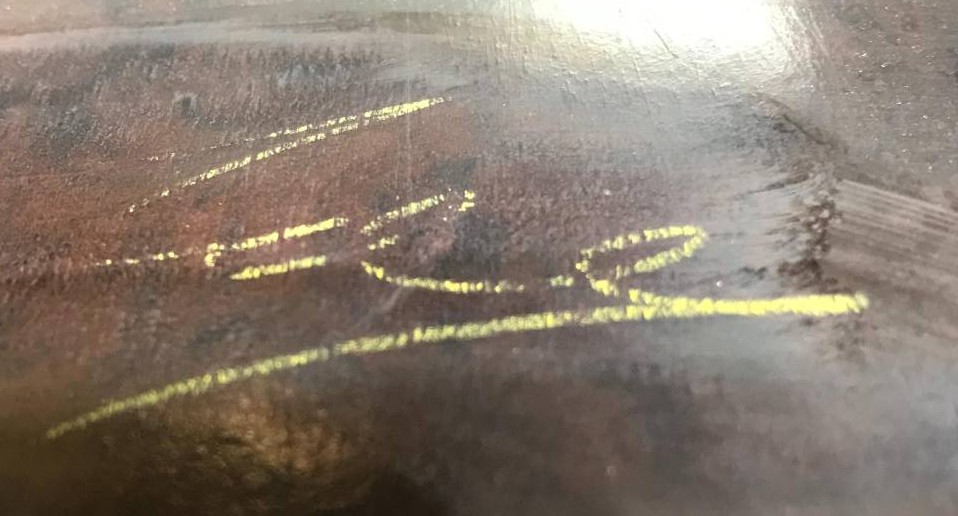
One nice thing I did discover during the disassembly of the receiver was the signature of the person that put the radio together during manufacture on the inside of the Bakelite cabinet.
1946 Philips receiver builder signature
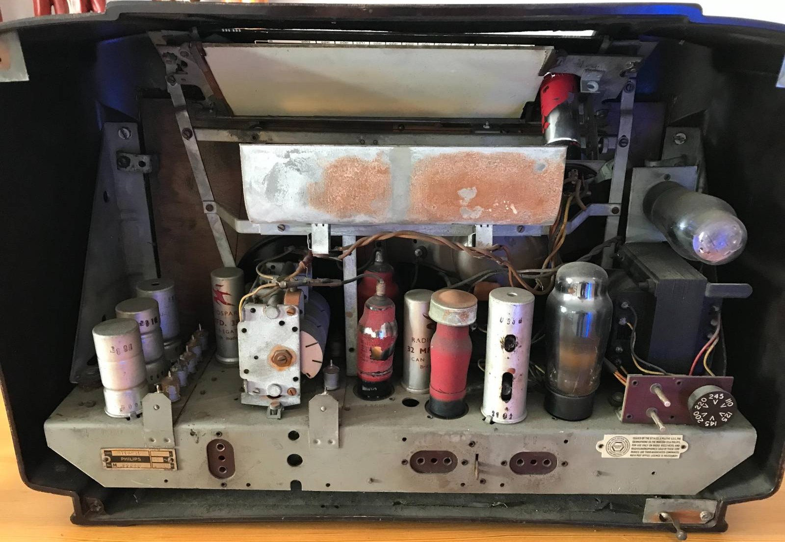
Getting the internals out of the cabinet was fun, so many little screws holding the old valve electronics and tuning display in place.
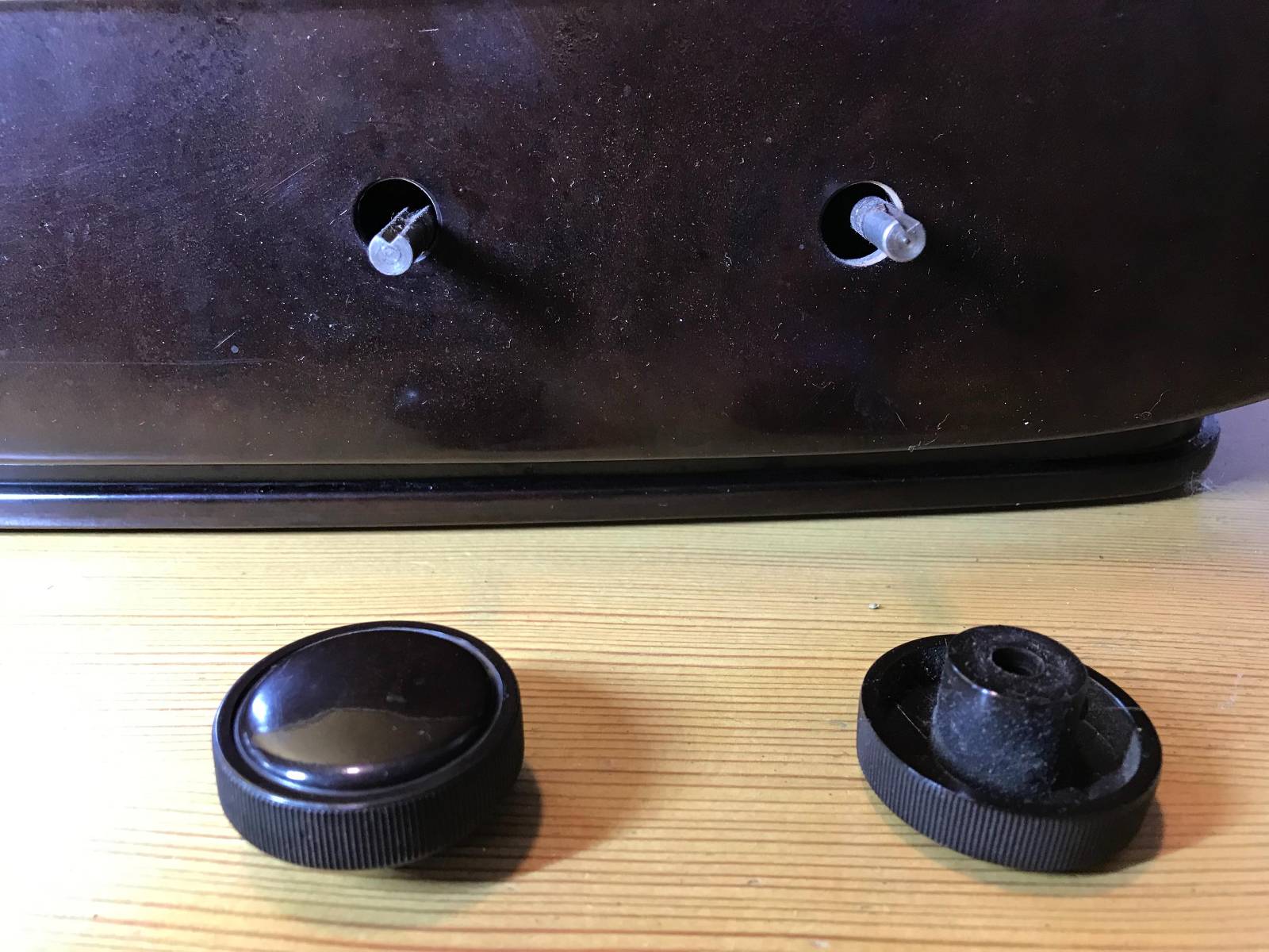
1946 Philips Receiver – Internal View1946 Philips receiver – removing the original control knobs
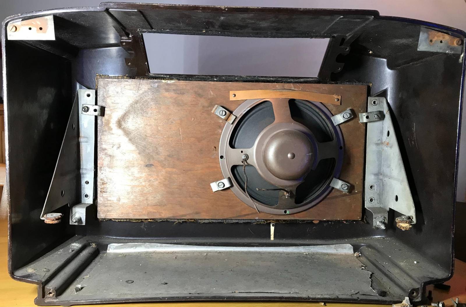
Once the electrical part of the radio was removed I gained access to the old speaker that was fitted to the front panel of the receiver. Unfortunately the speaker cone had a tear in it rendering it useless so I’ll need to get a new speaker(s) for the rebuild.
1946 Philips receiver speaker view
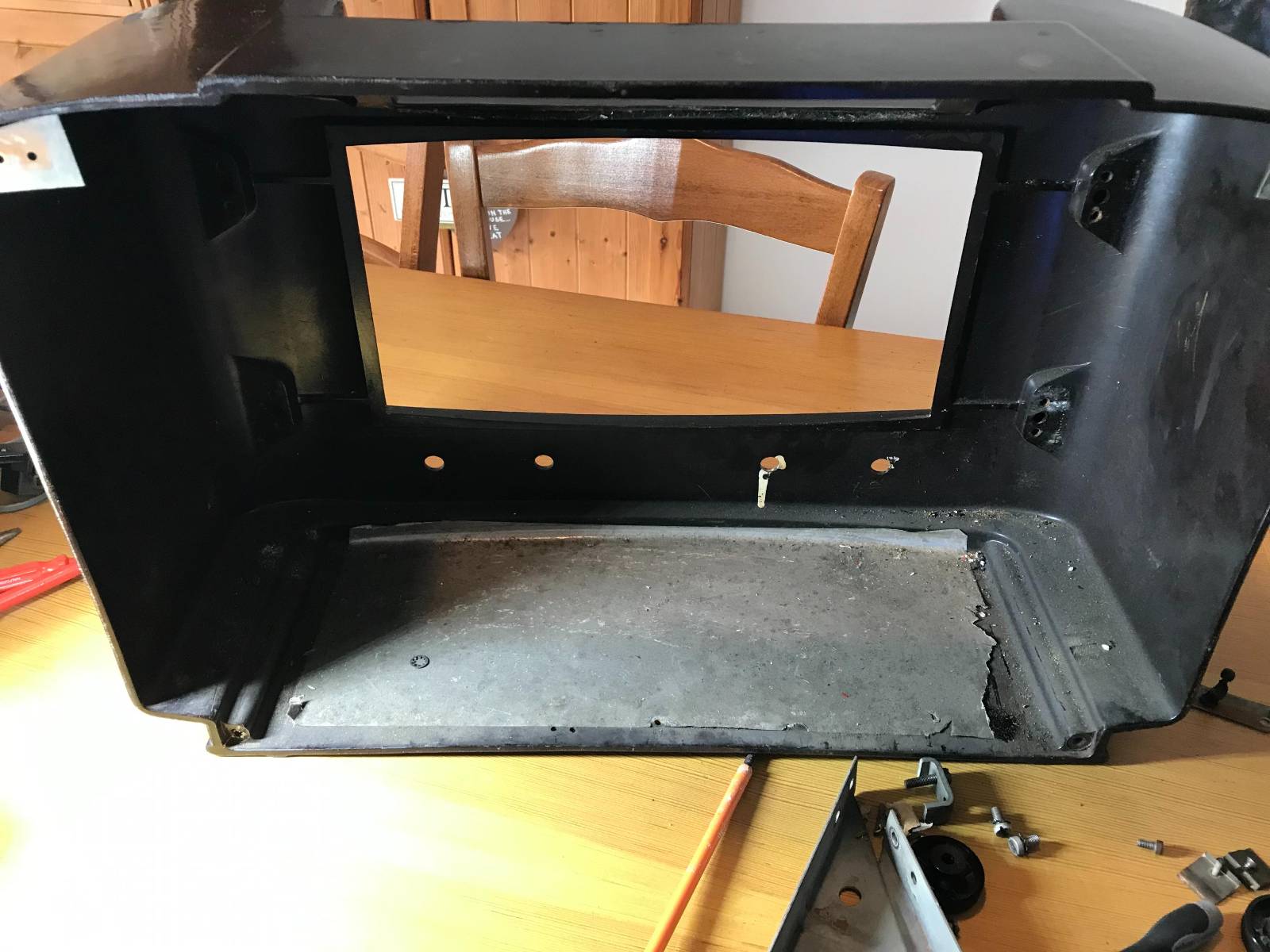
Once I got the speaker and fittings removed I set about cleaning the cabinet inside and out to remove the 79 years worth of dirt and grime that had collected within. The fascia of the receiver cabinet seems to have lost it’s shine and will need to be polished to get it back to it’s original beauty.
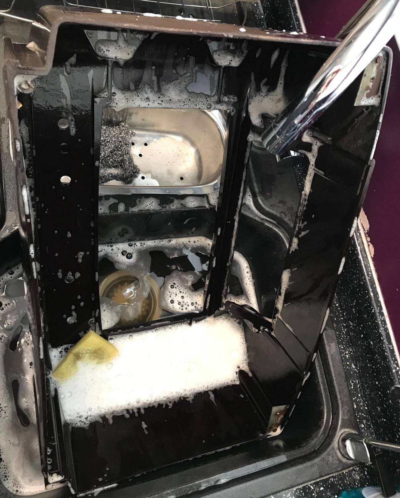
79 years worth of grime and dirt to be removed!Washing the Bakelite receiver case
It took 5 lots of fresh water and washing up liquid to get the cabinet clean. The first three lots of water looked like mud in no time at all such was the state of the cabinet.
With the cabinet now cleaned and put to one side to dry thoroughly I have started to search for the best type of polish to use to put the sheen back onto it.
Once I’ve got the cabinet looking good again I’ll start fitting the new internals. I also need to find a source for a new piece of material to cover the speaker hole at the front of the cabinet as the original material is looking somewhat tired.
The old Philips Emblem from 1946 on the receiver case
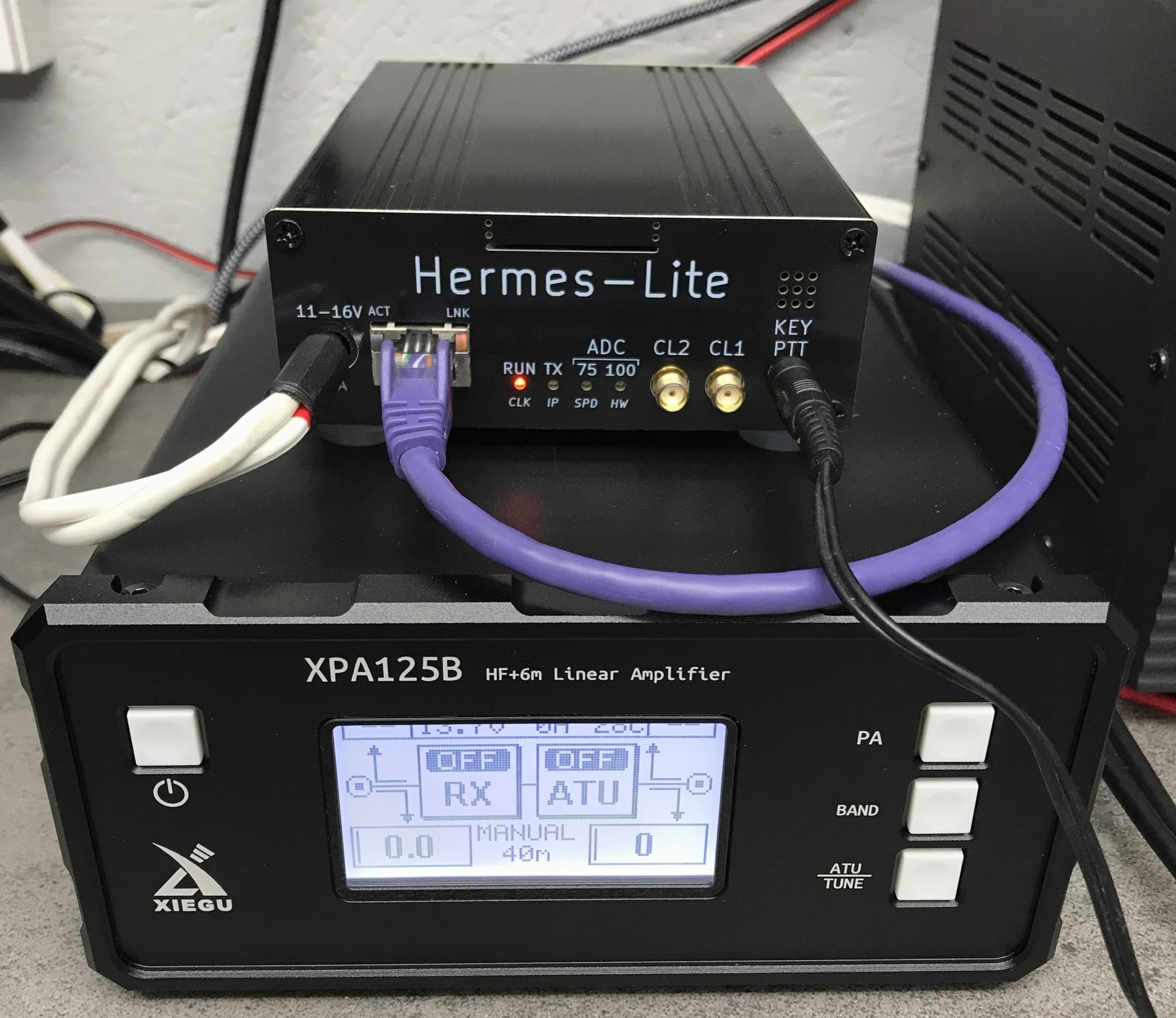
Since I’ve had my Hermes Lite 2 (HL2) and Xiegu XPA125B amplifier combo I’ve had to manually change the band setting on the amp as I never purchased the HL2 I/O board when I initially purchased the kit.
At the time I didn’t think I would need it but, changing band manually on the amp (and sometimes forgetting causing tuning issues) is a nuisance and so I put my hand in my pocket once again and ordered the I/O board for the HL2.
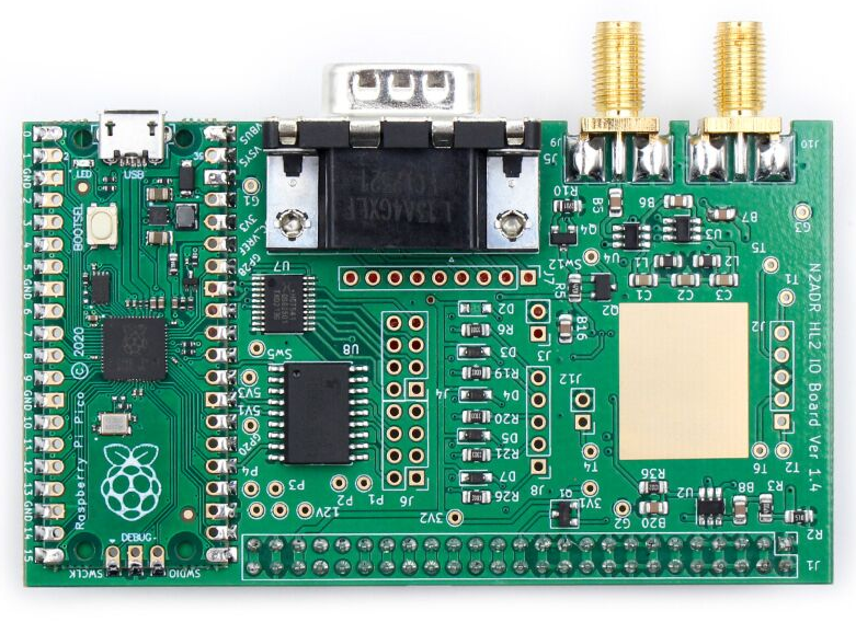
Hermes Lite 2 I/O Board
The HL2 I/O board is a small RaspberryPi Pico controlled device that can be used for a multitude of functions depending on the software loaded. Many people are writing their own software for the Pico to do things like control transverters, remote antenna switches, amplifiers and just about anything else you can think of. It’s a really versatile little add on board for the HL2.
The I/O board arrived after about 10 days from Makerfabs, all nicely packaged as always. Unfortunately due to Christmas, New year and other priorities it’s sat in the box since it arrived.
A couple of days ago I finally got round to getting it out of the box and set about configuring it to control the Xiegu amp.
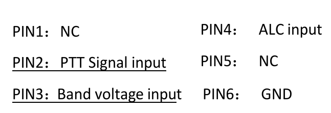
The Xiegu amp needs three connections from the I/O board. They are PTT, Band Switching Voltage and Ground. These are easily accessed from the I/O board via 3 jumper wires to connect to the DB9 connector on the rear of the board.
The other thing that is required is some software for the RaspberryPi Pico to control the whole process. Steve, M0XVT has kindly supplied me with a copy of the software.
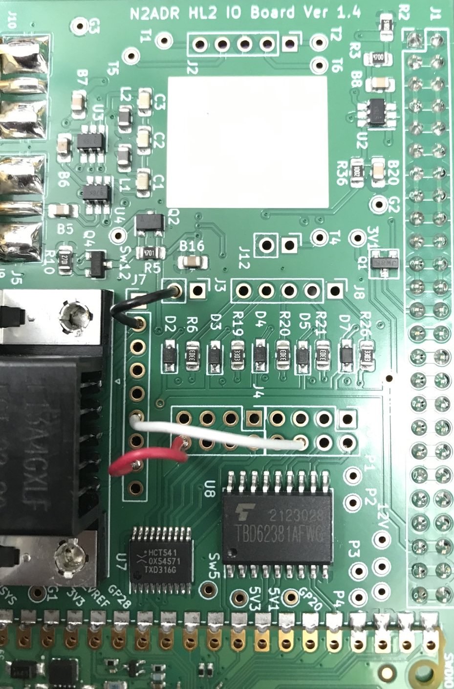
Soldering the jumpers from the relevant points on the circuit board to the DB9 connector was pretty straight forward. You can use any of the pins on the DB9 connector that you like as from the factory the DB9 connector isn’t connected to anything. I decided to use pins 2, 6 and 8 and so will refer to those pins from this point forward.
HL2 I/O Board Jumpers
I used a different colour for each of the jumpers so that I knew which jumper was for which connection. The colours used also match the colours of the wire in the old RS232 serial lead that I cannibalized to make the connection between the I/O board and the amp thus making it easy to ensure continuity.
The colours are as follows:
Black Jumper - Ground - Pin 2 on DB9 Connector
White Jumper - PTT - Pin 6 on DB9 Connector
Red Jumper   - Band Control - Pin 8 on DB9 Connector
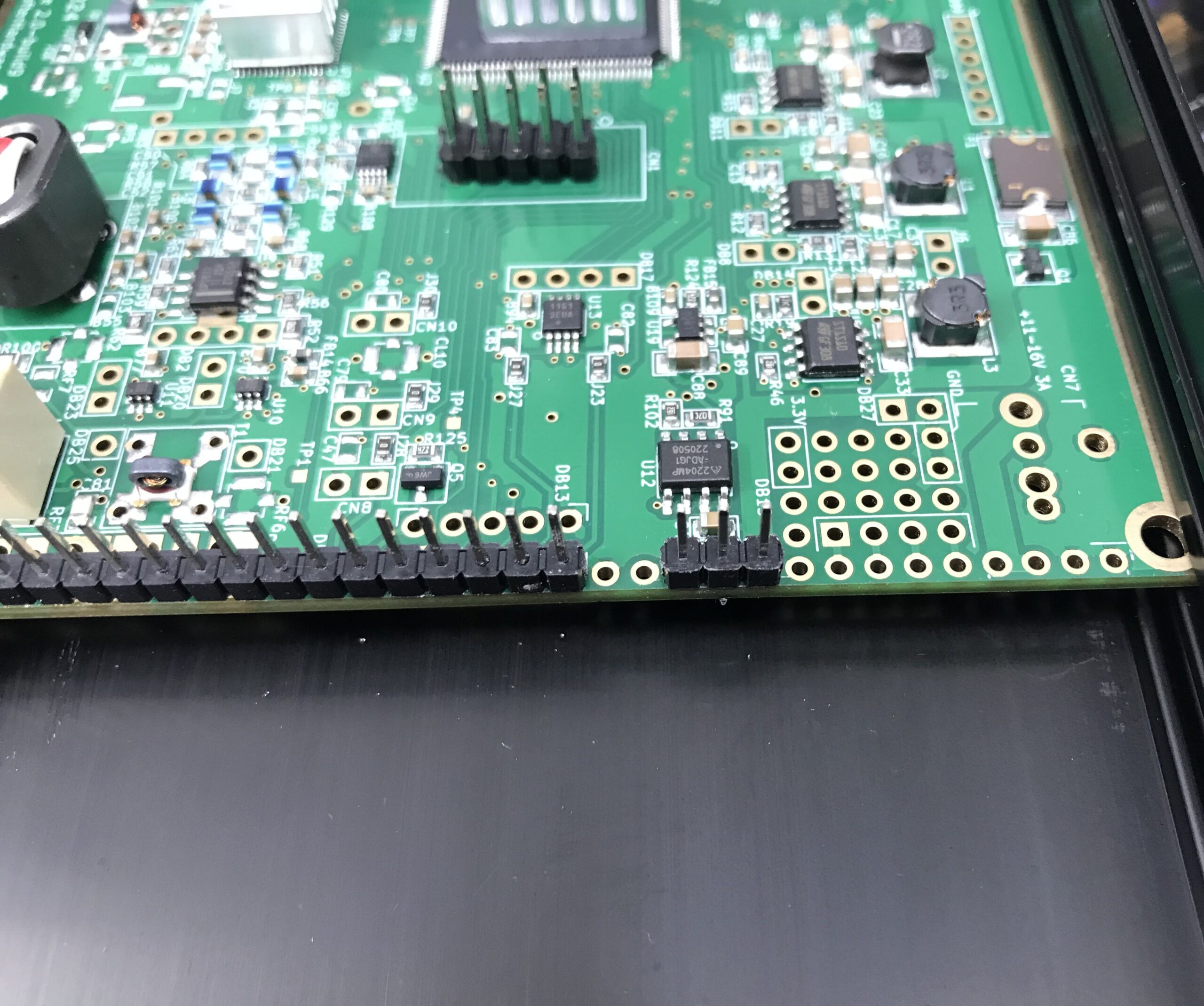
The I/O board gets its power feed directly from the HL2 main board however, the 3 pins it needs to connect to don’t have any headers in place and so, it’s necessary to solder a short row of 3 header pins onto the HL2 main board.
I found the easiest way to do this was to put the 3 header pins into the correct position and then use the HL2 to N2ADR filter board connector to hold them in place whilst soldering. This worked perfectly and I soon had the header pins soldered onto the main board.
Extra 3 header pins soldered to the main HL2 board
It’s important to note that the 3 extra header pins need to be placed 2 holes away from existing header pins as shown above. Take care to get these pins in the right position so as not to cause any damage to the 3 circuit boards once all are connected and powered up.
Note: The HL2 main board must be removed from the case to solder the extra 3 header pins in place. Take care to ensure the correct fitting of the PA heatsink when when refitting the HL2 main board into the case.
At this point I refitted the N2ADR Filter board back into the HL2 case so that the two sets of header pins aligned correctly ready for the placement of the new I/O board that would connect all 3 circuit boards together.
Preparing the N2ADR Filter board for reconnection
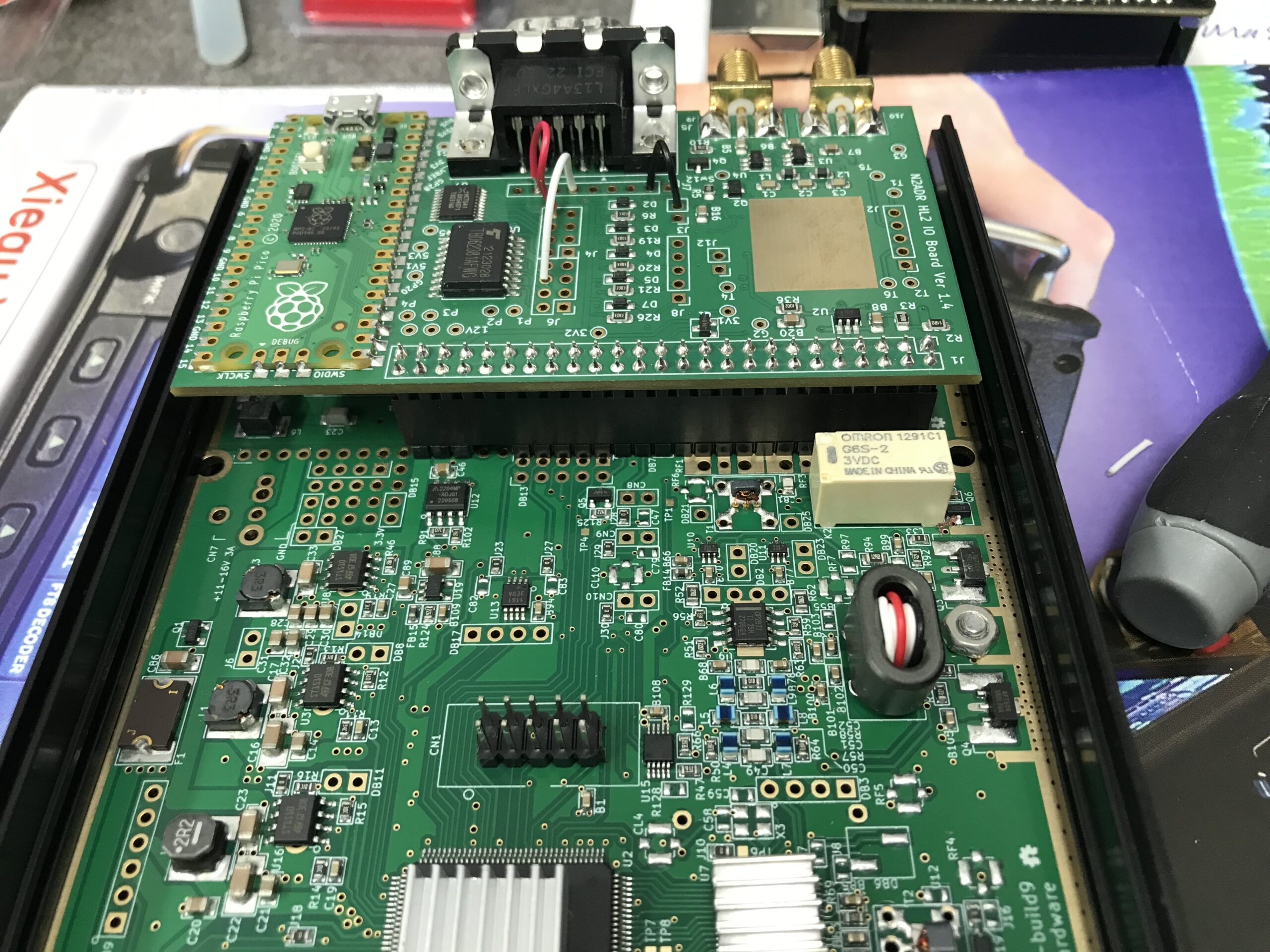
Once the filter board was in place I fitted the new I/O board taking care to ensure all pins aligned with the socket and then gently pushed it home.
Close up of the HL2 I/O board fitted to the main HL2 board and N2ADR Filter board
The close up of the I/O board connector above shows how the extra 3 header pins connect to the last 3 sockets in the I/O board connector. It’s a snug fit with the N2ADR filter board below it.
View of the fitted HL2 I/O board from above
Before the HL2 case can be put back together it’s necessary to load the software onto the RaspberryPi Pico (top left in photo above) that controls the I/O board.
This is accomplished by pressing the tiny button on the Pico whilst connecting a USB lead to the USB socket on the board that had already been plugged into my PC. Once connected the Pico appeared as a USB drive on my Kubuntu Linux desktop. All I then had to do was to copy the software file onto the drive. Once the software file is on the drive the Pico will reboot automatically and the little LED on the board will start to flash to show it has booted successfully. At this point I could safely unplug the USB cable.
The software for the RaspberryPi Pico is available for download below.
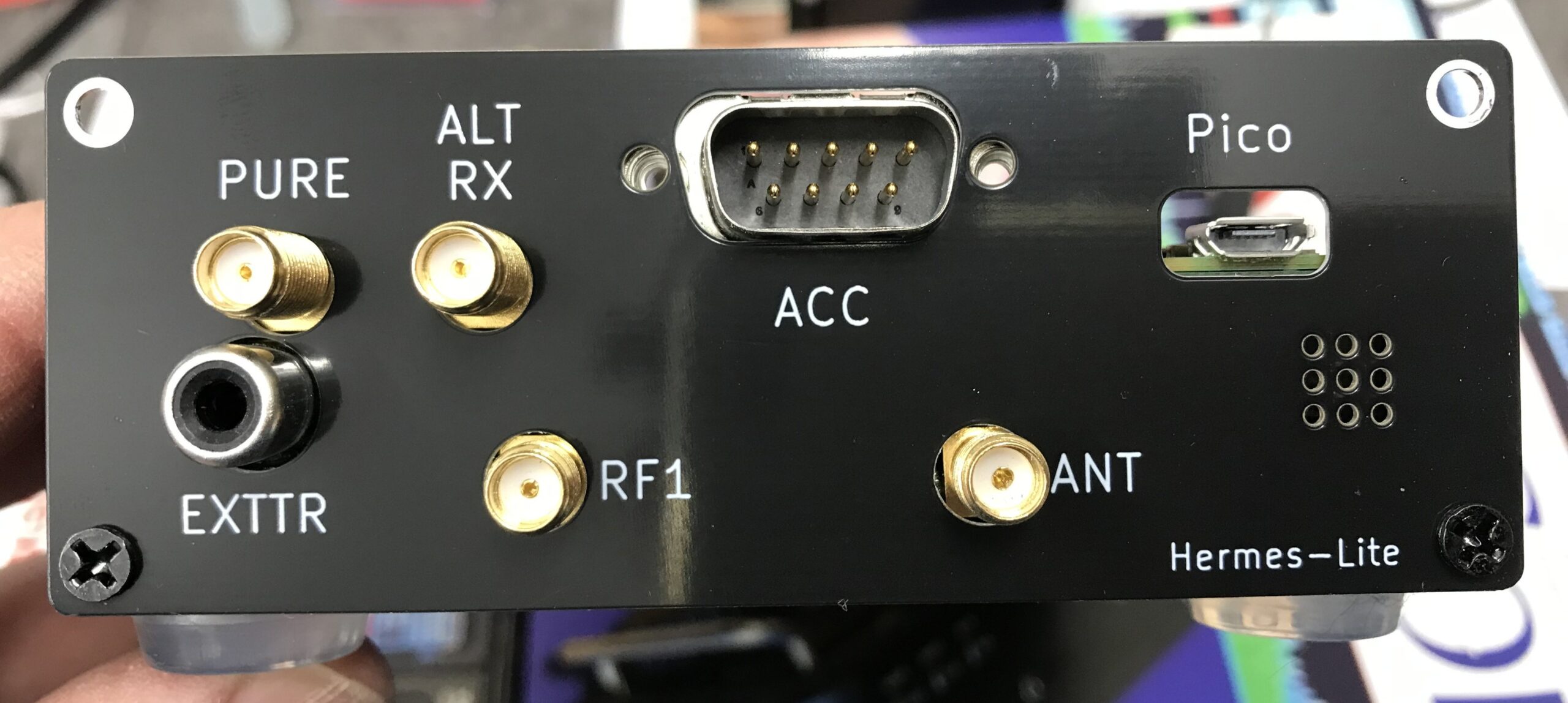
The I/O board comes with a new back panel for the HL2 to accommodate the extra connectors on the rear. Refit the top of the HL2 case and then attach the new rear panel using the original 4 counter sunk screws.
Supplied HL2 I/O board replacement rear panel fitted to the case
The final part of this project is to make the lead that will go from the HL2 rear DB9 ACC connector to the Xiegu XPA125B mini din ACC socket.
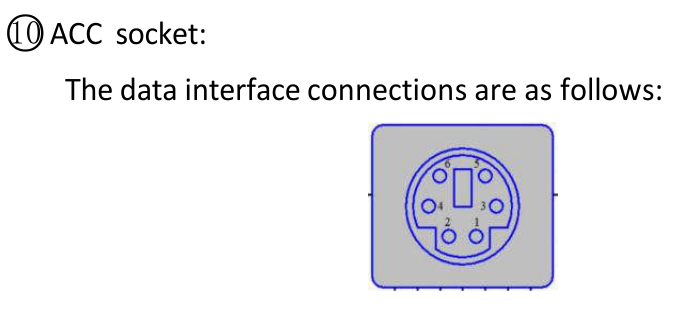
DB9 Pin 2 (BLACK) to Mini Din Pin 6 (GND)
DB9 Pin 6 (WHITE) to mini Din Pin 2 (PTT)
DB9 Pin 8 (RED) to Mini Din Pin 3 (Band Switching Voltage)
Below are a couple of screenshots from the Xiegu XPA125B user manual showing the Mini Din pin layout and the data interface connections for the amplifier.
Before I connected the lead to the two devices, I tested the end-to-end continuity of the lead to ensure all pins were correctly connected and that there were no shorts between any of the pins.
It’s important that the wires are connected to the correct pins on each end of the lead. Failure to ensure correct connection could cause damage to your HL2 and/or amplifier.
Once the lead had been tested, I connected it to both the Hermes Lite 2 and the Xiegu XPA125B amplifier. I also had to switch the amplifier band switching to AUTO.
Now when I change band on my HL2 in the PiHPSDR software the amplifier also changes band at the same time keeping the two devices in sync. No more manual band changing for me!
I hope this article is of use to other Hermes Lite 2 users who have purchased the Xiegu XPA125B but, have yet to setup auto band switching between the two devices.
Thanks to Steve, M0XVT for all the jumper information and the RaspberryPi Pico Software to get this all working.
UPDATE: The RaspberryPi Pico software originally came from Ramon, KP4RX. More information can found in this Google Groups article where he released the binary into the wild.
A full table of I/O resources available on the HL2 I/O board can be found on the KP4RX Guthub page.
The source code for the main.uf2 file above can be found at KP4RX.com
(This information is also for the Hermes Lite 2, Adalm Pluto, Pluto+ and LibreSDR)
During my RadioBerry build I started out using the version of PiHPSDR that was created just for the RadioBerry. The problem with this is that it is hard coded for a very small screen making it hard to use on a big screen since the user cannot resize the window dynamically.
I decided to look for a forked version of the PiHPSDR software that had the ability to change the window size to suit all use cases. During my search I stumbled across the DL1YCF fork of the source code that has some enhancements, one of which is the ability to change the display size.
In no time at all I had the source code downloaded and compiled only to find that it didn’t work with the RadioBerry. After some investigation I found that this was due to the fact that the RadioBerry software has compiled into it code that is used to access the GPIO pins on the RaspberryPi so that it can communicate with the RadioBerry HAT. This is fine except that the DL1YCF version of PiHPSDR also has code in it to use the GPIO pins. This of course causes a conflict and the net result is that nothing works.
Reading through the source code and Makefile I found that all I needed to do was to compile a version of PiHPSDR without GPIO support. This would then remove the conflict and allow the RadioBerry software to operate correctly.
To this end I put together a download/compile/install script for the DL1YCF version of PiHPSDR that will work on a RaspberryPi with a RadioBerry HAT and give the ability to resize the window to fit any size screen.
The script also works on a Linux Desktop PC running Ubuntu/Kubuntu/Linuxmint/Debian operating systems. (It will most likely work on other distro’s too but, these are all I have to hand currently). You can of course also use this software with a Hermes Lite 2 transceiver.
DL1YCF PiHPSDR running on RaspberryPi 4 with RadioBerry HAT on a large monitor
To install this enhanced version of PiHPSDR on your RaspberryPi/Desktop PC with GPIO support disabled, download the installation script below, unzip it and run it in a terminal on your RaspberryPi/Desktop PC in your home directory. (/home/<your-username>).
The script will download the latest source code from the DL1YCF github, disable the GPIO code and then compile and install it to your computer. If installing on a RaspberryPi it will create an icon on the desktop for you to use to start the software.
If installing on a PC then you will need to create your own desktop icon as the one created only works on a RaspberryPi. You can of course just start the software from the command line in a terminal. (My preferred method).
If you have a RaspberryPi 5 then I highly recommend that you run this version of PiHPSDR on it as it has a lot more computing power and handles using dual receive with ease. It will run on a Pi4 but, you will load the CPU more as it’s not as powerful as the later model Pi5.
The script will ask if you want to compile in SOAPYSDR support so that PiHPSDR will work with RTL-SDR, Adalm-Pluto, Pluto+ and LibreSDR. Enter Y to compile in support or N if you don’t need it.
For the last week or so I’ve been playing with a RadioBerry HAT for my RaspberryPi computer. The RadioBerry is a cut down version of the Hermes Lite 2 with just 20mW output power and separate TX and RX antenna ports. It’s a really neat little package that sits on top of a RaspberryPi4/5 and creates a neat little HF transceiver.
RadioBerry HAT
I initially started with the RadioBerry HAT on my Pi5 but, I soon realised that the software really doesn’t work well at all on the Pi5. I’m not 100% sure as to why but, for some reason it holds one core at 100% continuously. It seems that the RadioBerry software is single threaded. The end result is that on the Pi5 you cannot use a sample rate above 9600 before the IQ stream starts to stutter.
By contrast, installing the RadioBerry software onto a Pi4 it performs perfectly upto the maximum sample rate of 384000 without any stuttering. I’ll need to spend some time going through the source code to try and determine why it doesn’t work correctly on a Pi5.
Whilst going through the source I discovered that the developer has put some code in that collects data from the running computer and sends it to the developer’s website. Some of this data is then made public via his website, http://www.pa3gsb.nl/radioberry/api/read.php
One of the things displayed on the website is the Mac address of the RaspberryPi on which the RadioBerry is running. This is a security risk and should never be done!
The most annoying thing is that this is done without authorisation. The installation doesn’t state that it’s going to collect data every time you start your RaspberryPi computer nor does it offer the ability to opt out. It also doesn’t inform the user that it’s going to pass the data on to a third party. In some cases it even collects HAM Radio Callsign and location data and displays it on a public website, a clear breach of the UK/European Data Protection Law.
Finding spyware in open source software is really poor and something most open source developers would never consider doing.
To this end I have disabled the spyware in the version of the RadioBerry software that I am using and am making it available to everyone else to use via this blog.
So, to install the RadioBerry software you just need to download the installation script and run it in a terminal on your RaspberryPi computer.
The script will download the modified source code, compile it and install it on your RaspberryPi ready for you to use.
I encourage everyone that downloads the script and the source code to take a look at it and ensure you are happy with it. It’s important to know what you are running on your computer and what it does.
You can find the spyware code in the register.c file (It’s all commented out with “//” marks). The function now doesn’t pass any data at all to the public website.
I hope some of my readers who are experimenting with the RadioBerry transceiver find this useful.
I will soon be publishing an article on an enhanced version of PiHPSDR from DL1YCF to use with the the RadioBerry to complete the project.
Important Update:
There is an issue with the RadioBerry code that renders it useless if you use a kernel later than the version shown below:
Updating the O/S Kernel to any version later than the version shown above will stop the RadioBerry software from working. Recompiling of the code also fails due to the Kernel update and at the time of writing this cannot be fixed without a code rewrite by the original developer.
I also recommend that once you have built a working RadioBerry on a RaspberryPi 4 you should disable the automatic updates of the O/S to stop the system from failing in the future.
You can disable the automatic updates by entering the following commands into a terminal:
Many years ago when I lived in France I had a Flex-3000 transceiver, one of the first fully SDR transceivers on the market. It was paired with a proprietary Windows XP application called PowerSDR (now Opensource and called Thetis) and connected via a firewire connection.
17 years later I am once again venturing into the world of SDR transceivers in the form of a Hermes Lite 2. (HL2)
The HL2 hardware is available via the Makerfabs website in kit form. I ordered the HL2 motherboard, the N2ADR Filter Board to ensure a clean signal from the transceiver and the enclosure. Total cost for all the parts and shipping was £288.00 including all taxes.
The kit took about 10 or so days to arrive and was very easy to put together making sure to fit the PA transistor heat sink the right way round so that it doesn’t short out the main board. (There are many videos about this on YouTube)
Once the hardware was put together I needed to install some software to control/drive the HL2. Being a heavy weight Linux user my software choice had to come from the Opensource world.
M0AWS Hermes Lite 2 SDR Trasnceiver and Xiegu XPA125B Amplifier
After much research and chatting with other HAMs on the Matrix who have the HL2 I found that most people use the closed source SDR Console software to control the transceiver. Since this software is for Windows it’s not something I can use as I don’t have any Windows PCs, they’re all Linux only.
To this end I started researching Linux SDR software for the HL2 and decided that PiHPSDR was the one I was going to try first.
PiHPSDR was originally written for the RaspberryPi 3/4/5 single board computers (SBCs) but, I wanted to have a go at compiling it on my Kubunu Linux desktop PC. I found it straight forward to follow the instructions in the pihpsdr-install.pdf file and in no time at all I had the software compiled and running.
PiHPSDR running on Kubuntu Linux 22.04LTS
PiHPSDR is infinitely configurable and thus it feels like it has an infinite number of menus and options. Since the HL2 has two separate receivers, it’s possible to listen to two bands at the same time. This is the one feature I really missed more than anything with my FTDX10 so, I’m glad to have dual receive capability back once more!
Going through all the settings I realised that the A and B VFOs have individual settings. Initially I setup the software using just VFO A but, when I switched over to VFO B none of my settings were there. I then had the realisation that the settings apply only to the active VFO. I quickly went through all the settings again for VFO B and all was well.
In no time at all I was on the air with just 5w as my Xiegu amp hadn’t arrived. Not being perturbed I tuned up on the 15m band and started searching for stations. Interestingly it was CQWW SSB weekend and the band was full of contest stations. Working my way along the spectrum I found I was able to work quite a few stations with ease using my vertical and inverted-L antennas.
Contacts of note were VE3KG at 3406 Miles, VE3JM at 3382 Miles, RW9DX at 2380 Miles, KC1XX at 3331 Miles and N1DE at 3600 Miles. I also worked a bunch of European stations and had a great time giving away points with my little QRP rig.
Contests are a good time to try out new radios as all the big stations with good ears are on the bands and make the effort to get us QRP guys in their logs.
I have been extremely impressed with the receivers in the HL2 radio. It handles both strong and weak stations exceptionally well. PiHPSDR really does have brick-wall filtering and I was able to work the weaker stations right next to large contest stations with ease. At no time did the front-end of the receiver get overloaded.
Below is a short video clip of a conversation on the 80m band. The band was quite noisy however, with a reduction of the AGC gain and the 2700Hz filter it’s possible to remove almost all the noise.
Hermes Lite 2 SSB reception on the 80m Band
On CW the radio is a real delight. With the filtering and AGC gain control I am able to use extremely narrow receive filters without any ringing whatsoever. I would say that on CW the HL2 is as good as my FTDX10 when it comes to receiving even the weakest of stations.
I’m sure on paper the FTDX10 receiver has better numbers however, to the ear there really is no discernible difference.
Below is a short video clip of D4DX on CW on the 80m band. The band was noisy but, with the 100Hz filter enabled and clever use of the AGC Gain I was able to remove almost all the noise completely, reducing fatigue on the ears and making reception very easy even though there was some fairly deep QSB at times.
Receiving D4DX on CW on the 80m band using 100Hz filter and reduced AGC gain
A few days later my Xiegu XPA125B amplifier arrived. Unfortunately the amp didn’t come with the normal PTT lead that comes from the factory and is detailed in the user manual. For some bizarre reason this is a chargeable option when you buy the amp from Martin Lynch and Sons even though it is included from the factory.
This meant I had to make a lead which was a problem as I didn’t have one of the mini DIN plugs required for the connection to the amplifier. Jumping onto Amazon I ordered a packet of two and sat back and waited for their arrival.
A couple of days later the DIN plugs arrived and I quickly made up the necessary phono/RCA to mini DIN lead and got the amp operational.
The Xiegu XPA125B isn’t cheap but, it’s a really nice bit of kit. The neat little LCD display keeps you informed of power O/P, I/P and O/P SWR, voltage, current draw, temperature and band selected.
With just 0.7w of input from the HL2 I’m able to get a full 100w O/P from the amp. On the lower bands I have to reduce the O/P from the Hermes Lite 2 even further so that I don’t over drive the amp.
Being an avid Short Wave Listener (SWL) I wanted to see how the HL2 performed when listening to the big AM broadcast stations. To my surprise it makes an excellent SWL receiver with better AM demodulation than many of the more expensive radios. Having the option to select receive filters up to 16Khz wide I found I was able to get the best audio possible from many of the broadcast stations including Radio Caroline on 648Khz. It’s quite an improvement over the 12Khz maximum on the FTDX10.
Listening to AM Broadcast stations
What makes this project even more exciting is that both the hardware and software are from the OpenHardware/OpenSource world. The complete circuit diagram, PCB layout and information is available for all to download, something you don’t often see these days!
PiHPSDR is one of the nicest SDR applications I’ve seen in the Linux world and even comes with a 200 page downloadable user manual. Something you don’t see in many Opensource projects. The source code for the application is downloadable and you are able to make your own changes to it without restriction.
Overall I am really pleased with the Hermes Lite 2 SDR transceiver. It has two excellent receivers, is infinitely configurable via the PiHPSDR software and performs extremely well under all conditions. Since getting the radio I haven’t even switched on the FTDX10.
More soon …
We use cookies to ensure that we give you the best experience on our website. If you continue to use this site we will assume that you are happy with it.