Node-Red Control Dashboard for AllStarLink 3

I’ve recently built a new AllStarLink (ASL) node for my MB7IBW gateway that I have recently brought up on air on the 2m band.

AllStarLink 3 has a lot of changes in it when compared to the previous version and this of course impacts my Node-Red Control Dashboard that I’ve been using to manage my first ASL node for well over a year now.

To build the node I used the RaspberryPi imager and added the AllStarlink 3 image as detailed on the allstarlink.org website.

Installing the system this way makes it pretty easy compared to previous installs but, it comes with some quirks which cause issues with Node-Red.

From the outset the plan has always been to have AllStartLink 3 and Node-Red running on the same Pi4 to keep it totally self contained. This was easy enough to achieve and works without issue.
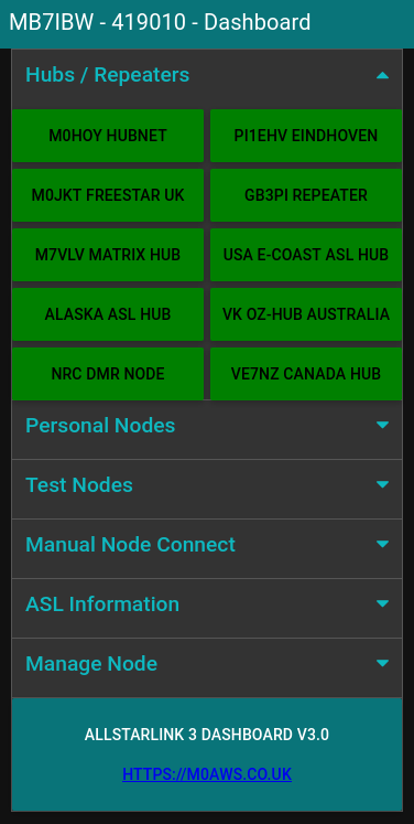
Node-Red Control Dashboard for AllStarLink 3

Installing Node-Red onto a Pi4 is really easy and is fully documented on the Node-Red Website.

Once the AllStarLink 3 operating system was installed on my SD card, booted and operational I installed Node-Red. I soon realised that there were a few things I had to do before loading the Node-Red flow.

AllStarLink 3 no longer logs connect and disconnect messages in the connectlog like it did in AllStarLink 2. To get logging working again I had to create two new BASH scripts as detailed below and put them into /etc/asterisk/myscripts.

For the connect information I created the BASH script as detailed below.

#!/bin/bash

# /etc/asterisk/myscripts/connectlog.sh

echo $1 Connected $2  on $(date +"%T") - $(date +"%m-%d-%Y")  >> /var/log/asterisk/connectlog

For the disconnect information I created the 2nd script detailed below.

#!/bin/bash

# /etc/asterisk/myscripts/disconnectlog.sh

echo $1 Disconnected $2  on $(date +"%T") - $(date +"%m-%d-%Y")  >> /var/log/asterisk/connectlog

Once these scripts were created I had to change the ownership and privileges as detailed below.

cd /etc/asterisk/myscripts
chown asterisk:asterisk ./*
chmod 750 ./*

I also had to change ownership/privileges of /etc/asterisk/myscripts.

cd /etc/asterisk
chown asterisk:asterisk ./myscripts
chmod 755 ./myscripts

Once the two scripts were in place I had to alter the asterisk config so that it called the scripts as part of the connect/disconnect process.

I found the connpgm and discpgm entries in /etc/asterisk/rpt.conf and changed them as shown below.

connpgm = /etc/asterisk/myscripts/connectlog.sh

discpgm = /etc/asterisk/myscripts/disconnectlog.sh

Next I disabled the temporary filesystems that are used by default for the apache and asterisk logging as it’s useful to keep the apache logs for debugging and I needed the asterisk logs for the Node-Red dashboard.

Disabling the temporary file system is very easy to do, just edit the /etc/fstab and comment out the two lines as shown below.

# Comment out the next line for persistent Apache logs
#tmpfs  /var/log/apache2        tmpfs   defaults,noatime,nosuid,nodev,noexec,mode=0775,size=32M 0 0

# Comment out the next line for persistent Asterisk logs
#tmpfs  /var/log/asterisk       tmpfs   defaults,noatime,nosuid,nodev,noexec,mode=0775,size=32M,uid=102,gid=106 0 0 

# Note: These lines are wrapped, should be on 1 line in the /etc/fstab

Once the entries in the /etc/fstab were commented out I rebooted the Pi4 to get persistent filesystems.

The final thing that had to be done was to allow user repeater to use sudo without a password so that it could be used to perform reboot/shutdown/process restart as user root from within the dashboard.

# /etc/sudoers

# Allow repeater sudo without password
repeater ALL=(ALL) NOPASSWD: ALL

Once this was all done I imported the Node-Red flow, configured the SSH nodes with login credentials for the Pi4 (important to use the user repeater for SSH), clicked deploy and the dashboard was ready for use.
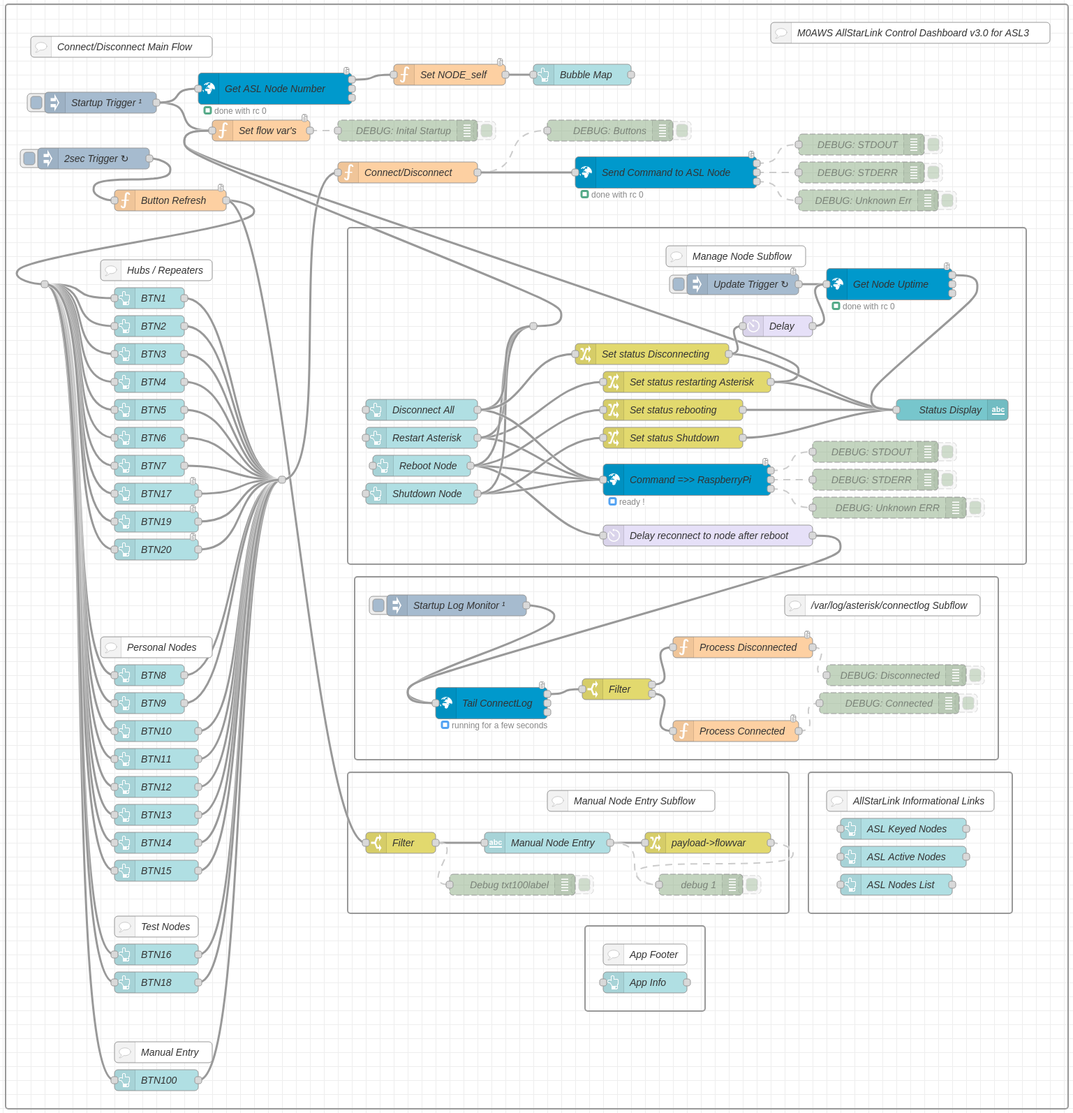
Node Red AllStarLink3 Control Dashboard Flow

I’ve been using the dashboard for a few weeks now and it’s running perfectly, without error.

If you want to build your own Node-Red Control Dashboard for your AllStarLink 3 node then, just download the flow using the button below and import it into your flow editor.


More soon …

Using Node-Red to build interactive log maps

I’ve not been on the radio much over the last few weeks as I’ve had my head down other radio related rabbit holes.

One of the rabbit holes is a Node-Red project to make my online logs a little more interactive. For sometime now my logs have been displayed on my website as nicely formatted, searchable HTML pages however, they don’t really allow the viewer (myself included) to see the global coverage of all the contacts so, I decided to write a Node-Red flow that would do just that.

M0AWS Interactive Log Flow

The flow itself isn’t too complicated and basically consists of reading in the individual ADIF formatted log files, processing the data and then sending the data in the correct format to the map node for display.

I’ve had to write a few functions to handle the processing of the ADIF formatted data but, these aren’t particularly complex and are fairly easy to understand even if like me, you’re not a Javascript programmer.

The flow is working perfectly however, I’m in the process of reworking the format generic payload function to reduce the amount of code and make it more efficient.

M0AWS SSB / CW / FreeDV Interactive Log World Map
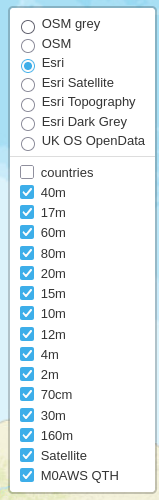
M0AWS Interactive Log Map Layers Menu


The flow generates two maps, one for voice / CW /Satellite contacts and the other for WSJT-X FT4/8 contacts. Every pin on the map is colour coded by band with satellite contacts being denoted by a satellite icon.

Each pin / icon on the map is clickable and reveals the data of the QSO being displayed.

In the top right-hand corner of the map there is a drop down layer menu that allows the viewer to filter by band thus reducing the number of icons on the screen at any one time.

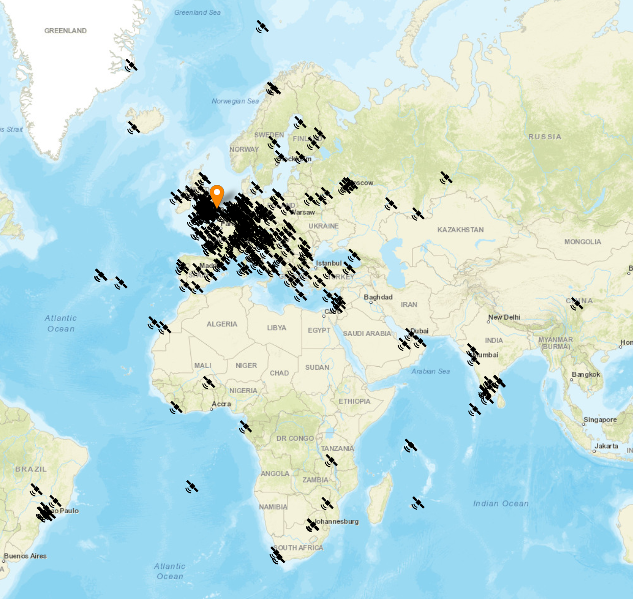
Seeing the data presented on a map really brings my logs alive. An example of this is that I had no idea I’d worked so many stations in India on the QO-100 Satellite.

The small icons in the pins show a microphone for SSB/FM/FreeDV contacts and a downwards pointing triangle in a box for CW contacts. Sadly I couldn’t find a Morse key icon in the collection available.

M0AWS filtered view of QO-100 Satellite contacts

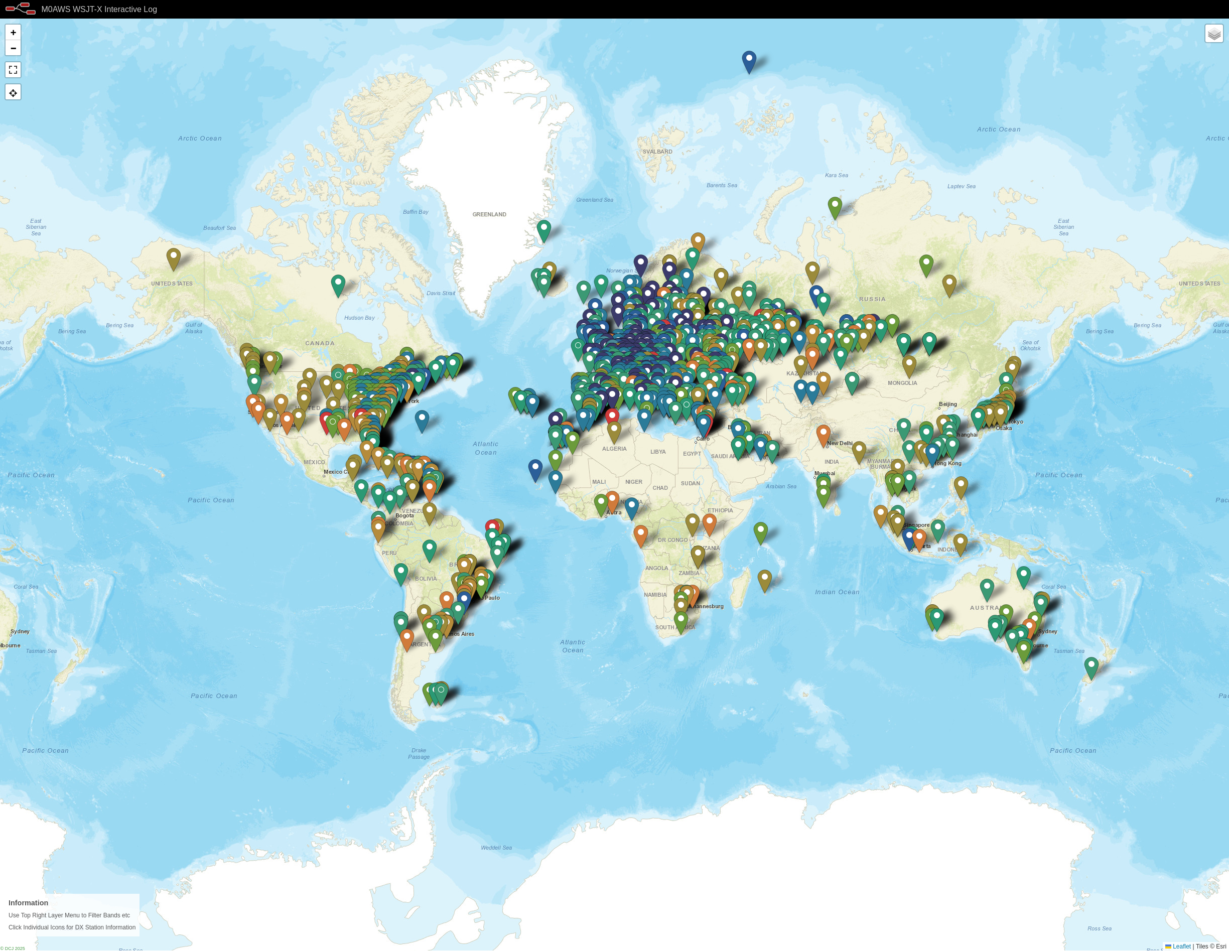
I only use FT4/8 for testing new antenna designs however, it’s interesting to see the global coverage accomplished with this weak signal mode.

M0AWS WSJT-X FT4/8 Interactive Log World Map

Once I’ve finished rewriting the format generic payload function I will make the flow available for download here so that others can also create an interactive view of their radio logs.

If you want to have a look at the maps and try them out for yourself, they are available under the Logs menu above.

This Node-Red instance is running in a virtual machine (VM) on a 16GB RAM RaspberryPi 5 that is also running a number of other VMs at the same time so, it’s safe to say it’s not heavy on CPU and will run on the older Pi4 as well.

More soon …

Xiegu XPA125b Cooling System

I’ve been using my Xiegu XPA125b amplifier with my Hermes Lite 2 SDR transceiver for some time now and have found it to be a great performer. The only issue I have with the amplifier is that it is passively cooled with the operating temperature often reaching in excess of 50 degrees Celsius. There is an air vent on the right-hand side of the amplifier case and then a very small vent on the rear where the end of the PA heatsink is however, air flow is really poor and so the heatsink can get saturated with heat very easily.

Having recently purchased a Bambu Lab A1 Combo 3D printer I’d already decided I was going to have a go at designing and making a fan assisted cooling system for the Xiegu amplifier.

Having no experience and very little knowledge of 3D printing I dived in head first and hit the vertical learning curve head on. In a fairly short period of time I had put together a design that would work.

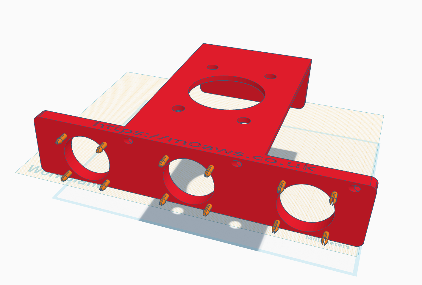
Designing the Xiegu XPA125b cooling system using tinkerCAD.
Designing the Xiegu XPA125b cooling system using TinkerCAD.

After 11 design versions and 3 x 3D prints I had a solution that fitted perfectly every time. Getting the 12v fans from Amazon was fairly cheap and I soon had the amp cooler working with a temperature reduction of 20-25 degrees Celsius during long waffle overs on the 80/60m bands. The amp now runs nice and cool with great airflow through the heatsink.

Next I wanted to add a Hermes Lite 2 cradle to the cooler solution so that two devices are neatly stacked together. Like the cooler design, I already had ideas in my head and just needed to get them down in the CAD package.

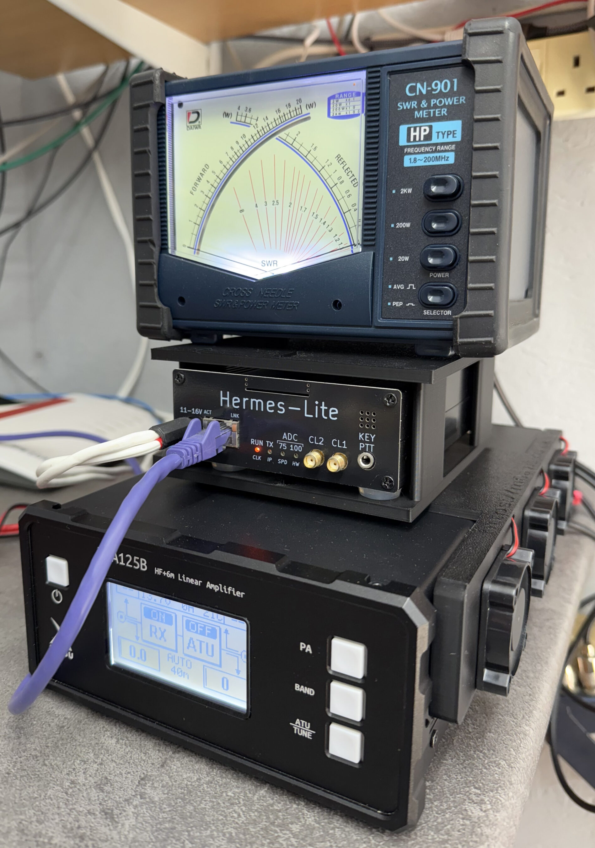
After some tinkering and 3 test prints I had a solution designed that not only created a cradle for the Hermes Lite 2 but, also a top shelf for my Daiwa CN901HP to sit on.

This brought the whole HF transceiver setup together nicely with all the components now being held in place securely.

Xiegu XPA125b Cooler with Hermes Lite 2 cradle - front view
Xiegu XPA125b Cooler with Hermes Lite 2 cradle – front view
Xiegu XPA125b Cooler with Hermes Lite 2 cradle - side view
Xiegu XPA125b Cooler with Hermes Lite 2 cradle – side view

The 3 fans on the side of the amp are silent which is great, there is a little noise from the air flowing through the case and out the vent at the back of the unit however, it’s barely noticeable. Keeping the case pressurized with cool air and forcing the heat out the rear vent has made a massive difference to the overall temperature of the amp even during long hours on air.

This has been a fun project and a great introduction to 3D printing, I’ve got so many more 3D print ideas now, I think I’ll be spending a lot of time in TinkerCAD.

I’ve just printed and put together a cooler and HL2 cradle for Steve, M0XVT and will be making them to order soon so, if you have a Xiegu XPA125b and want it to run a lot cooler then keep an eye on my website for details of how to buy one.

More soon …

1946 Philips 170A-15 RadioBerry Receiver Project

Back in January 2025 I wrote an article about a little RadioBerry Project I’d started that was based around a very old Philips 170A-15 receiver from 1946.

The idea of the project was to build a nice shortwave receiver for the radio shack based around the RadioBerry HAT on a RaspberryPi 4 housed in a vintage receiver cabinet.

The project has taken longer than I imagined due to getting side-tracked by other projects that I already had ongoing.

1946 Philips 170A-15 Shortwave Receiver Internal View

With the original internals removed there’s plenty of room inside for the RadioBerry, RaspberryPi 4 and the small 15w audio amplifier. The audio is delivered via a pair of Celestion speakers that I had that were originally part of an old surround sound TV system.

Power distribution is achieved very simply using a multi-plug adapter that also has USB A connections in it. The whole thing is then powered via one 240v mains cable.

The screen fits over the original opening for the glass tuning display and is held in place by two mounting screws on the rear of the LCD panel.

I purchased some new speaker grill cloth from Amazon and remade the speaker grill front with cut outs for the speakers. It looks really tidy and matches the rest of the bakelite cabinet nicely.

1946 Philips 170A-15 Shortwave Receiver RadioBerry HAT on RaspberryPi 4

To finish the project off I need to purchase 3 rotary encoders so that I can have a VFO knob and two more knobs for other things (to be determined). The Volume control is already in place with the original knob fitted to it. It will be nice to complete the 4 knob line up.

1946 Philips 170A-15 Shortwave Receiver Rear Panel

I had to make a couple of fittings top and bottom to hold the original rear panel in place but, it worked out just fine and I only had to fit an SO239 antenna connector and ethernet RJ45 port so that it can be connected to my local LAN.

Receiving radio Caroline on 648Khz

The audio quality from the little RadioBerry and 15w amp is pretty good. With the speakers hidden nicely behind the refurbished speaker grill the project looks quite tidy!

It also makes a great receiver for the HAM bands with it’s coverage of 100Khz to 30Mhz.

The DL1YCF Enhanced fork of PiHPSDR works really well on the touchscreen and provides a modern control interface to the RadioBerry HAT.

Listening to the 20m HAM Band

I’ll drop a final article once I have purchased the 3 rotary encoders to fill the 3 remaining holes in the front of the cabinet.

More soon …

Using AI to generate modern QSL Cards

With the recent explosion of artificial intelligence (AI) art generators that are making the news of late for all the wrong reasons, I decided to see if I could put it to good use and design some futuristic QSL cards.

Having recently been contacted by the Special Callsigns QSL Manager and being advised that there were 18 QSL cards waiting for me, I decided it was time to create some QSL cards of my own for future use.

Having never used any form of online AI and not having any artistic abilities I was amazed how easy it was to create images using nothing more than a paragraph or so of text to describe what it was I wanted to create.

Since all the QSL cards I received were for contacts on the QO-100 satellite, I set out to create a visually futuristic QSL card that was based around a radio HAM operator and satellite communications.

M0AWS - 1st attempt to create a futuristic QSL card using AI Art
M0AWS – 1st attempt at creating a futuristic QSL card image using AI Art

To my surprise the results of my first image generation were surprisingly good. The AI generated an image that resembled the simple text that I entered, although I never requested a one legged HAM operator!

Pleased with my very first attempt I gradually improved the description of what I was looking for, adding more and more detail to the text and including things that I wanted to see in the image. Over a fairly short period of time this approach started to generate some very interesting images.

With each iteration I gradually got closer to what I was trying to achieve but, never quite got exactly what I wanted so, I decided to rewrite the descriptive text adding even more information than before. The text was now a full blown paragraph with quite specific things described including the angle at which the scene was being viewed from.

The other option I wanted to try out was the theme functionality that the AI offered. This allows you to set a theme for the image from things like steampunk, cartoon, manga, real world and many more. The results were quite impressive and added yet another angle to the image generation.

I disappeared down the theme AI Art generation rabbit hole for quite some time and generated some very interesting and fun results. The best by far though was the Thunderbirds themed image, this did put a smile on my face!

M0AWS - AI Art QSL Thunderbirds Themed
M0AWS – AI Art QSL Thunderbirds Themed

At the other end of the spectrum I tried the Salvador Dalli theme, it produced an image that was very like the work of the famous artist but, wasn’t quite what I was looking for.

M0AWS - AI Art QSL Salvador Dalli Themed
M0AWS – AI Art QSL Salvador Dalli Themed

After much fun I eventually settled on the image I was after, a futuristic scene of a radio HAM with a satellite ground station over looking a mountain range and city below.

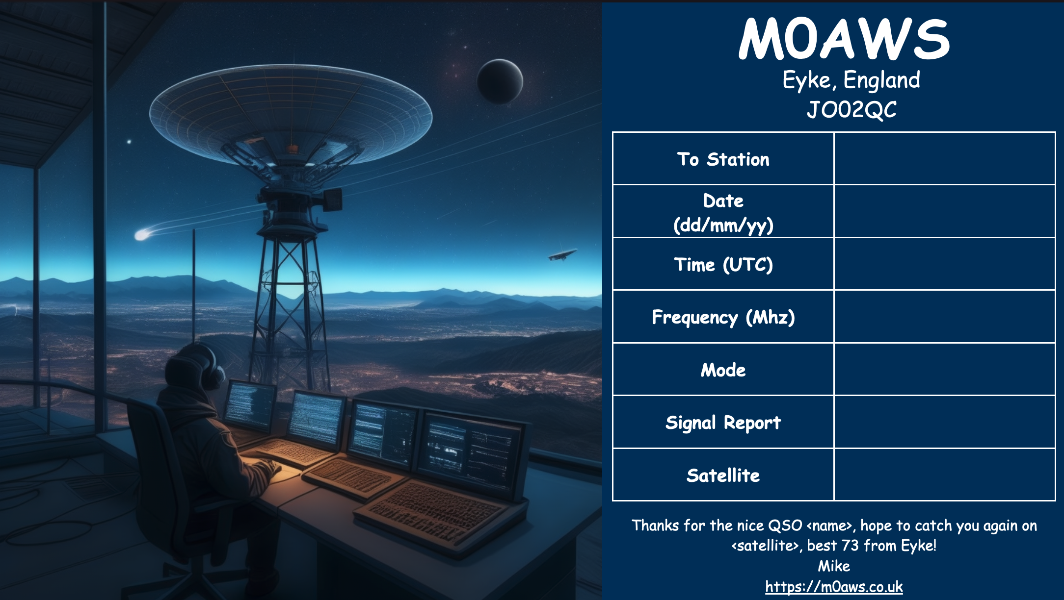
M0AWS Satellite QSL Card generated using online AI

I’m really pleased with the results from my ventures into AI generated art. The next challenge is to create a QSL card for HF bands Contacts.

More soon …