Sometime back I purchased a RadioBerry HAT for my RaspberryPi 4 single board computer (SBC) to use as an experimental platform to test PiHPSDR software modifications and to test changes to the actual RadioBerry software. With these two projects completed I decided that the receiver on the RadioBerry was so good it would be a shame not to put it to good use.
RadioBerry HAT
For many decades I’ve been an avid Short Wave Listener (SWL) but, haven’t had a general coverage receiver for many years. The RadioBerry fills this gap in my radio lineup perfectly but, needs to be put into a suitable cabinet with speakers, display, control knobs and antenna connections.
Rather than just buy another bland square box I decided it would be nice to repurpose an old, vintage radio receiver from a bygone era and bring it into the 21st Century.
1946 Philips valve radio receiver
After much searching on the popular auction sites online I eventually found the perfect old receiver for the project, a vintage Philips 170A-15 valve receiver from 1946.
This lovely old Art Deco looking receiver is made from Bakelite which was an early type of plastic made from phenol-formaldehyde resin, obtained from coal tar and methanol.
The full specification for the receiver can be found on the Radio Museum Website.
Sadly this is a non working example of this lovely old receiver and so I don’t feel so guilty stripping it out and replacing it’s internals with the RadioBerry.
1946 Philips receiver Serial Number plate1946 Philips receiver Licence Plate
Having the original serial number and Licence plate on the radio is nice, it also makes it easy to search for information about the old receiver.
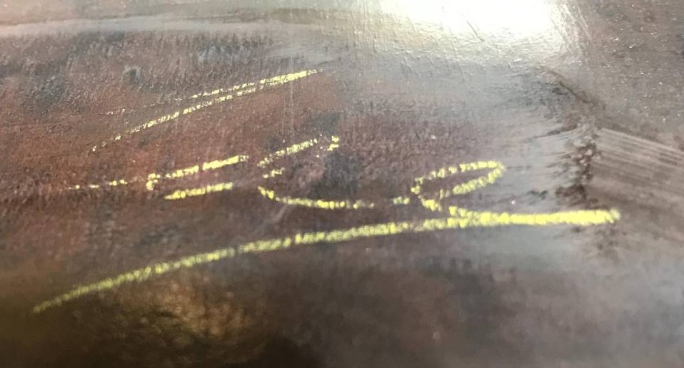
One nice thing I did discover during the disassembly of the receiver was the signature of the person that put the radio together during manufacture on the inside of the Bakelite cabinet.
1946 Philips receiver builder signature
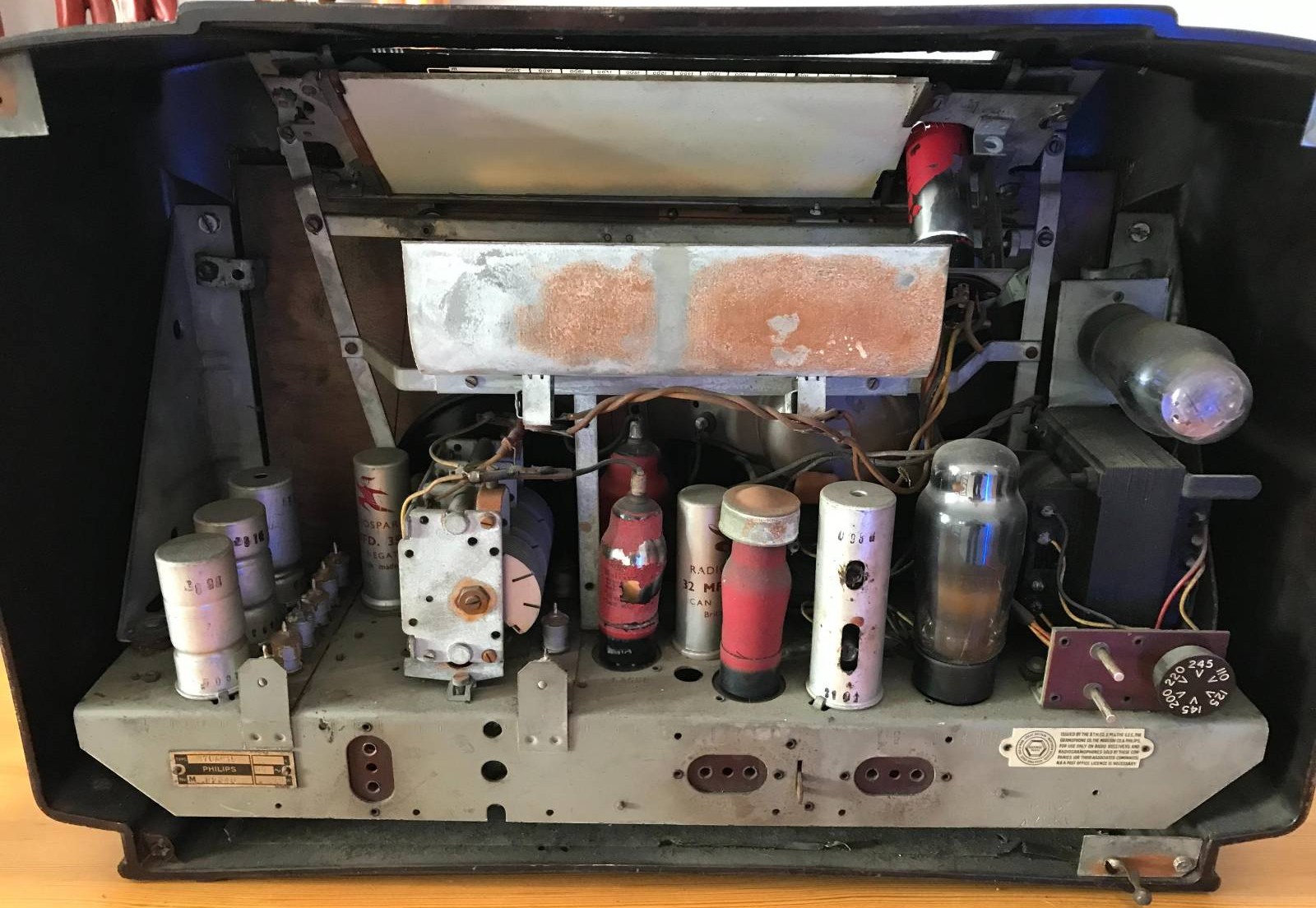
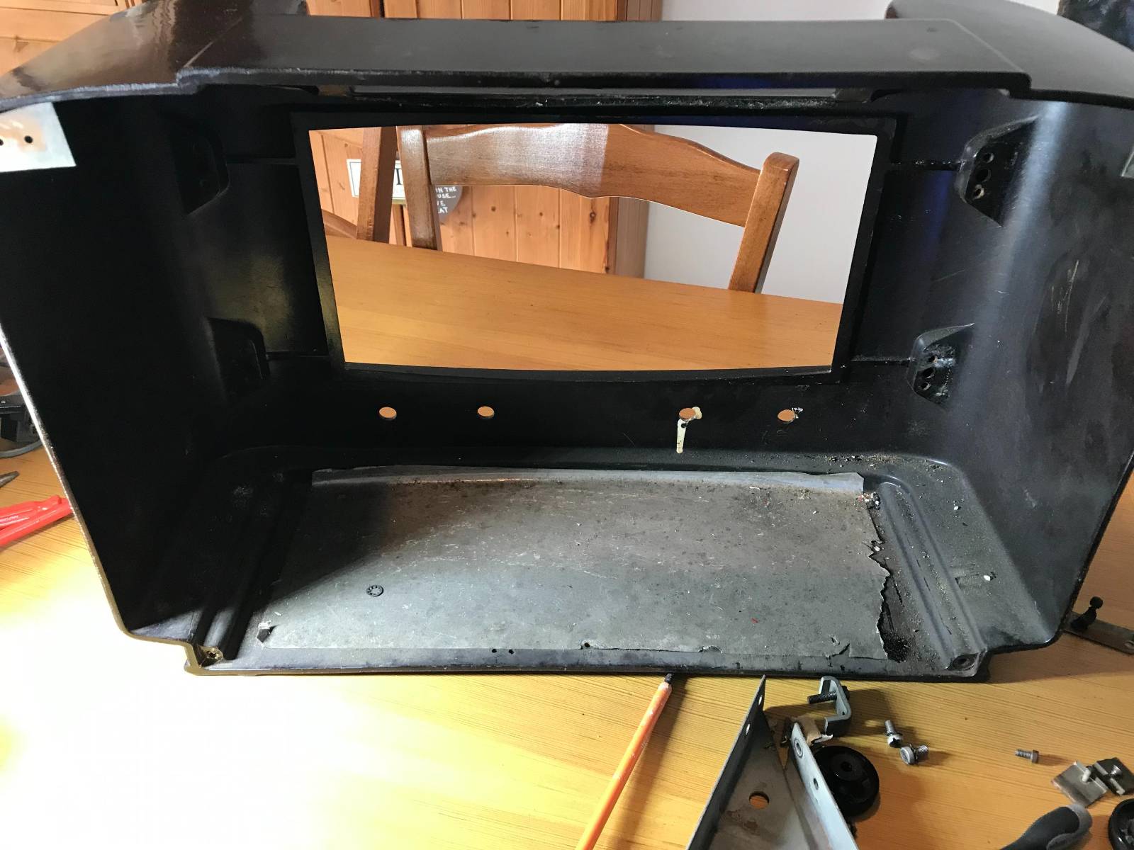
Getting the internals out of the cabinet was fun, so many little screws holding the old valve electronics and tuning display in place.
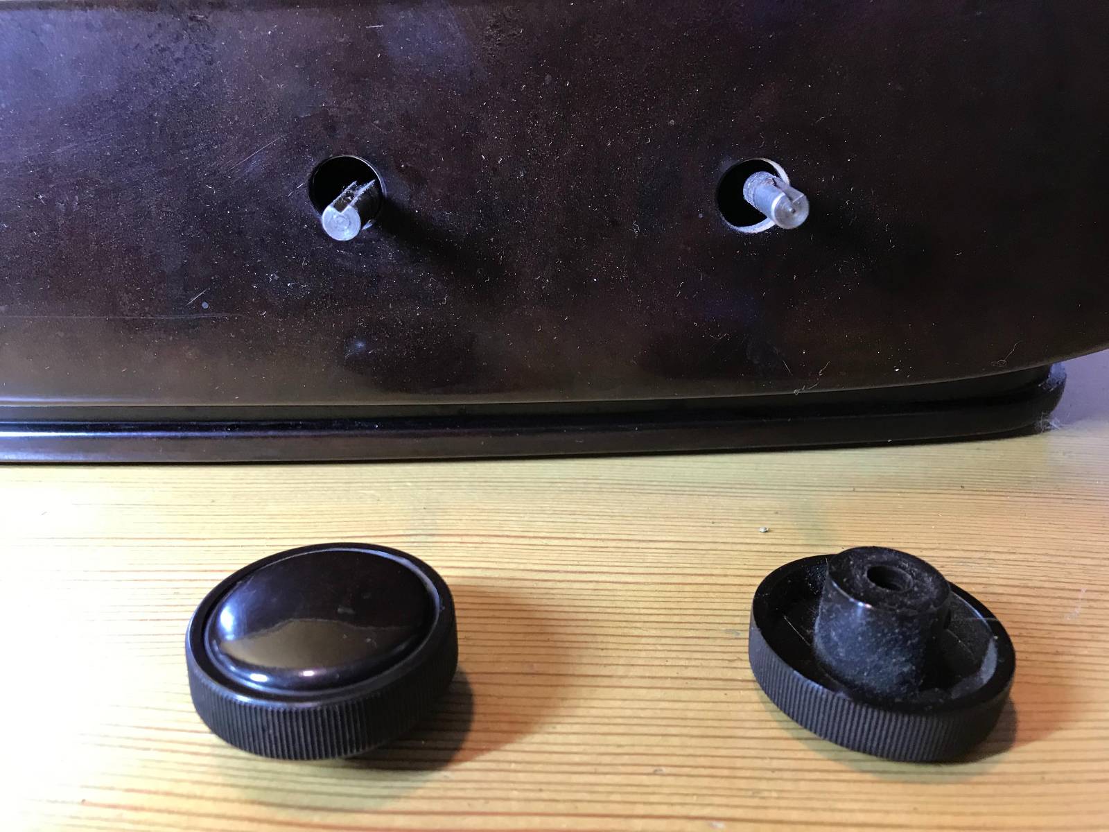
1946 Philips Receiver – Internal View1946 Philips receiver – removing the original control knobs
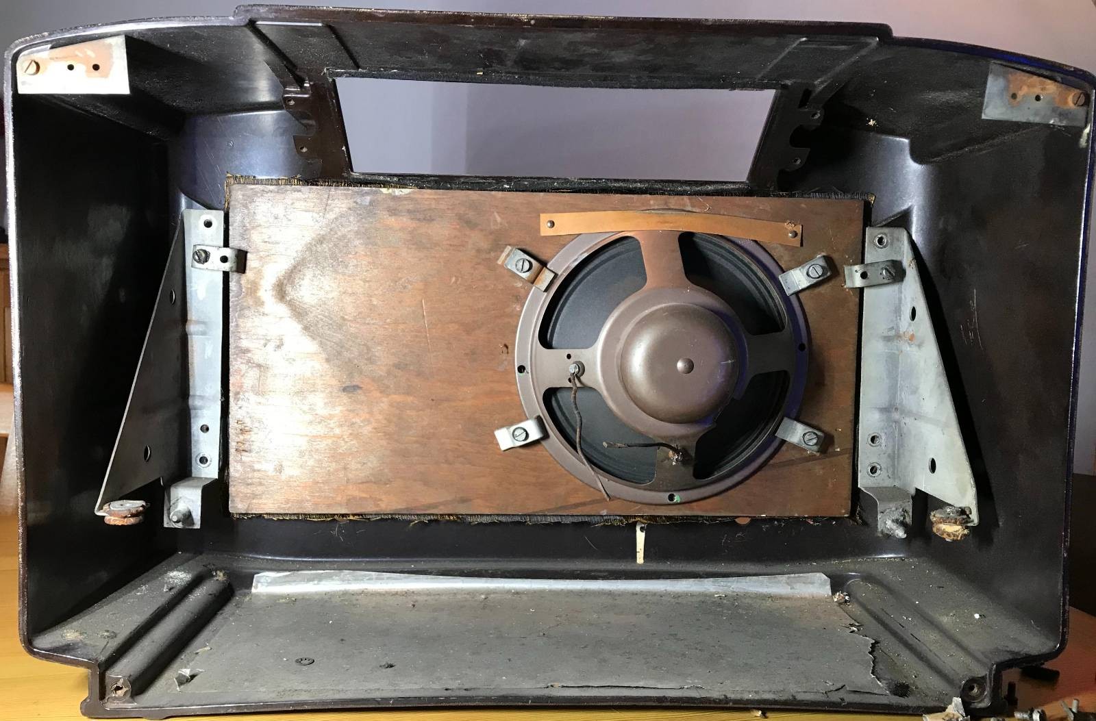
Once the electrical part of the radio was removed I gained access to the old speaker that was fitted to the front panel of the receiver. Unfortunately the speaker cone had a tear in it rendering it useless so I’ll need to get a new speaker(s) for the rebuild.
1946 Philips receiver speaker view
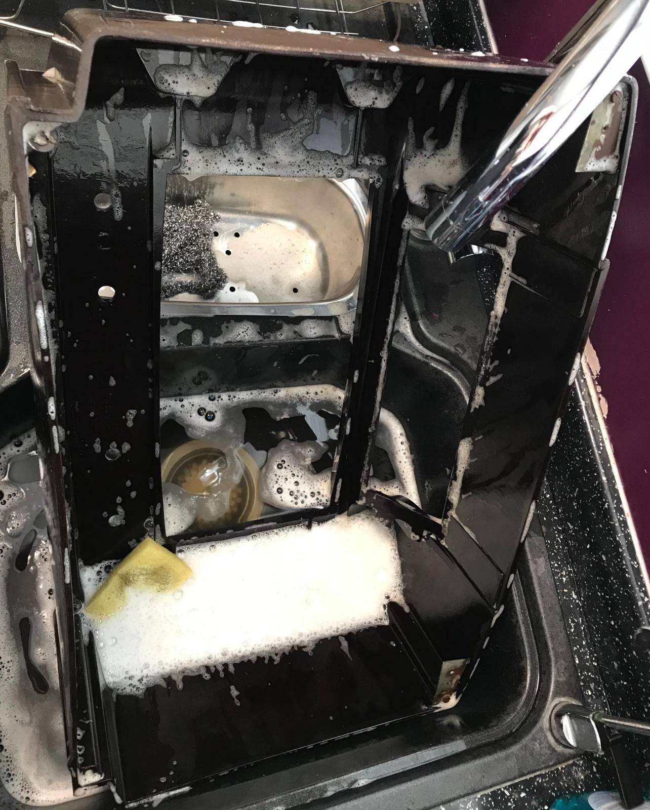
Once I got the speaker and fittings removed I set about cleaning the cabinet inside and out to remove the 79 years worth of dirt and grime that had collected within. The fascia of the receiver cabinet seems to have lost it’s shine and will need to be polished to get it back to it’s original beauty.
79 years worth of grime and dirt to be removed!Washing the Bakelite receiver case
It took 5 lots of fresh water and washing up liquid to get the cabinet clean. The first three lots of water looked like mud in no time at all such was the state of the cabinet.
With the cabinet now cleaned and put to one side to dry thoroughly I have started to search for the best type of polish to use to put the sheen back onto it.
Once I’ve got the cabinet looking good again I’ll start fitting the new internals. I also need to find a source for a new piece of material to cover the speaker hole at the front of the cabinet as the original material is looking somewhat tired.
The old Philips Emblem from 1946 on the receiver case
Since I’ve had my Hermes Lite 2 (HL2) and Xiegu XPA125B amplifier combo I’ve had to manually change the band setting on the amp as I never purchased the HL2 I/O board when I initially purchased the kit.
At the time I didn’t think I would need it but, changing band manually on the amp (and sometimes forgetting causing tuning issues) is a nuisance and so I put my hand in my pocket once again and ordered the I/O board for the HL2.
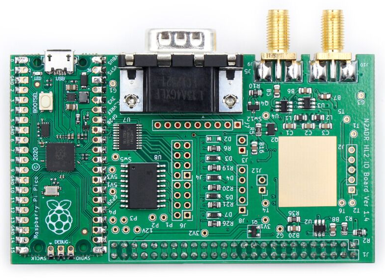
Hermes Lite 2 I/O Board
The HL2 I/O board is a small RaspberryPi Pico controlled device that can be used for a multitude of functions depending on the software loaded. Many people are writing their own software for the Pico to do things like control transverters, remote antenna switches, amplifiers and just about anything else you can think of. It’s a really versatile little add on board for the HL2.
The I/O board arrived after about 10 days from Makerfabs, all nicely packaged as always. Unfortunately due to Christmas, New year and other priorities it’s sat in the box since it arrived.
A couple of days ago I finally got round to getting it out of the box and set about configuring it to control the Xiegu amp.
The Xiegu amp needs three connections from the I/O board. They are PTT, Band Switching Voltage and Ground. These are easily accessed from the I/O board via 3 jumper wires to connect to the DB9 connector on the rear of the board.
The other thing that is required is some software for the RaspberryPi Pico to control the whole process. Steve, M0XVT has kindly supplied me with a copy of the software.
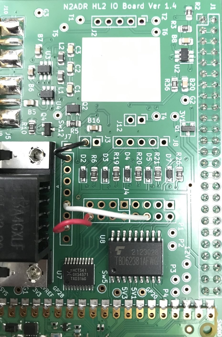
Soldering the jumpers from the relevant points on the circuit board to the DB9 connector was pretty straight forward. You can use any of the pins on the DB9 connector that you like as from the factory the DB9 connector isn’t connected to anything. I decided to use pins 2, 6 and 8 and so will refer to those pins from this point forward.
HL2 I/O Board Jumpers
I used a different colour for each of the jumpers so that I knew which jumper was for which connection. The colours used also match the colours of the wire in the old RS232 serial lead that I cannibalized to make the connection between the I/O board and the amp thus making it easy to ensure continuity.
The colours are as follows:
Black Jumper - Ground - Pin 2 on DB9 Connector
White Jumper - PTT - Pin 6 on DB9 Connector
Red Jumper   - Band Control - Pin 8 on DB9 Connector
The I/O board gets its power feed directly from the HL2 main board however, the 3 pins it needs to connect to don’t have any headers in place and so, it’s necessary to solder a short row of 3 header pins onto the HL2 main board.
I found the easiest way to do this was to put the 3 header pins into the correct position and then use the HL2 to N2ADR filter board connector to hold them in place whilst soldering. This worked perfectly and I soon had the header pins soldered onto the main board.
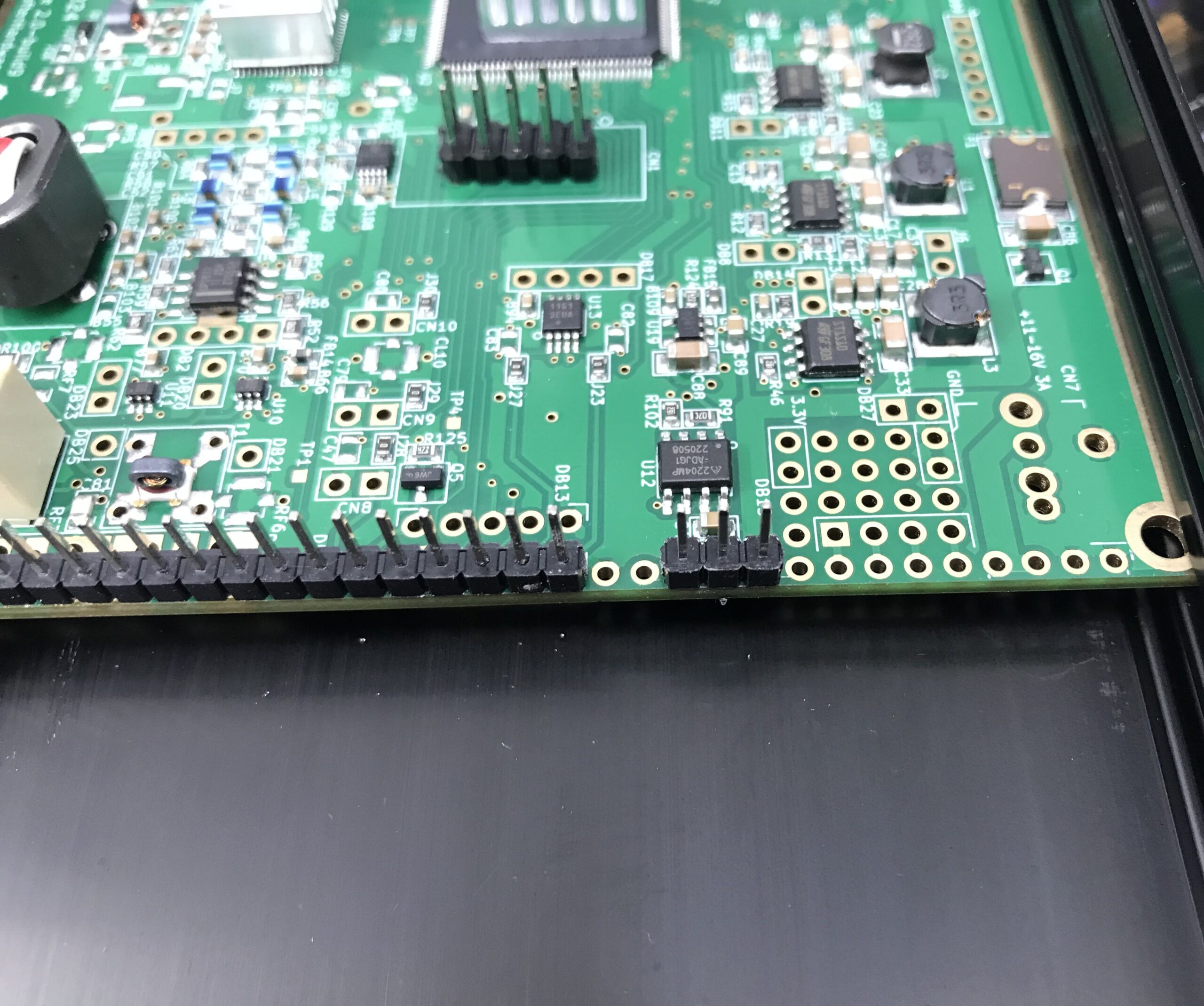
Extra 3 header pins soldered to the main HL2 board
It’s important to note that the 3 extra header pins need to be placed 2 holes away from existing header pins as shown above. Take care to get these pins in the right position so as not to cause any damage to the 3 circuit boards once all are connected and powered up.
Note: The HL2 main board must be removed from the case to solder the extra 3 header pins in place. Take care to ensure the correct fitting of the PA heatsink when when refitting the HL2 main board into the case.
At this point I refitted the N2ADR Filter board back into the HL2 case so that the two sets of header pins aligned correctly ready for the placement of the new I/O board that would connect all 3 circuit boards together.
Preparing the N2ADR Filter board for reconnection
Once the filter board was in place I fitted the new I/O board taking care to ensure all pins aligned with the socket and then gently pushed it home.
Close up of the HL2 I/O board fitted to the main HL2 board and N2ADR Filter board
The close up of the I/O board connector above shows how the extra 3 header pins connect to the last 3 sockets in the I/O board connector. It’s a snug fit with the N2ADR filter board below it.
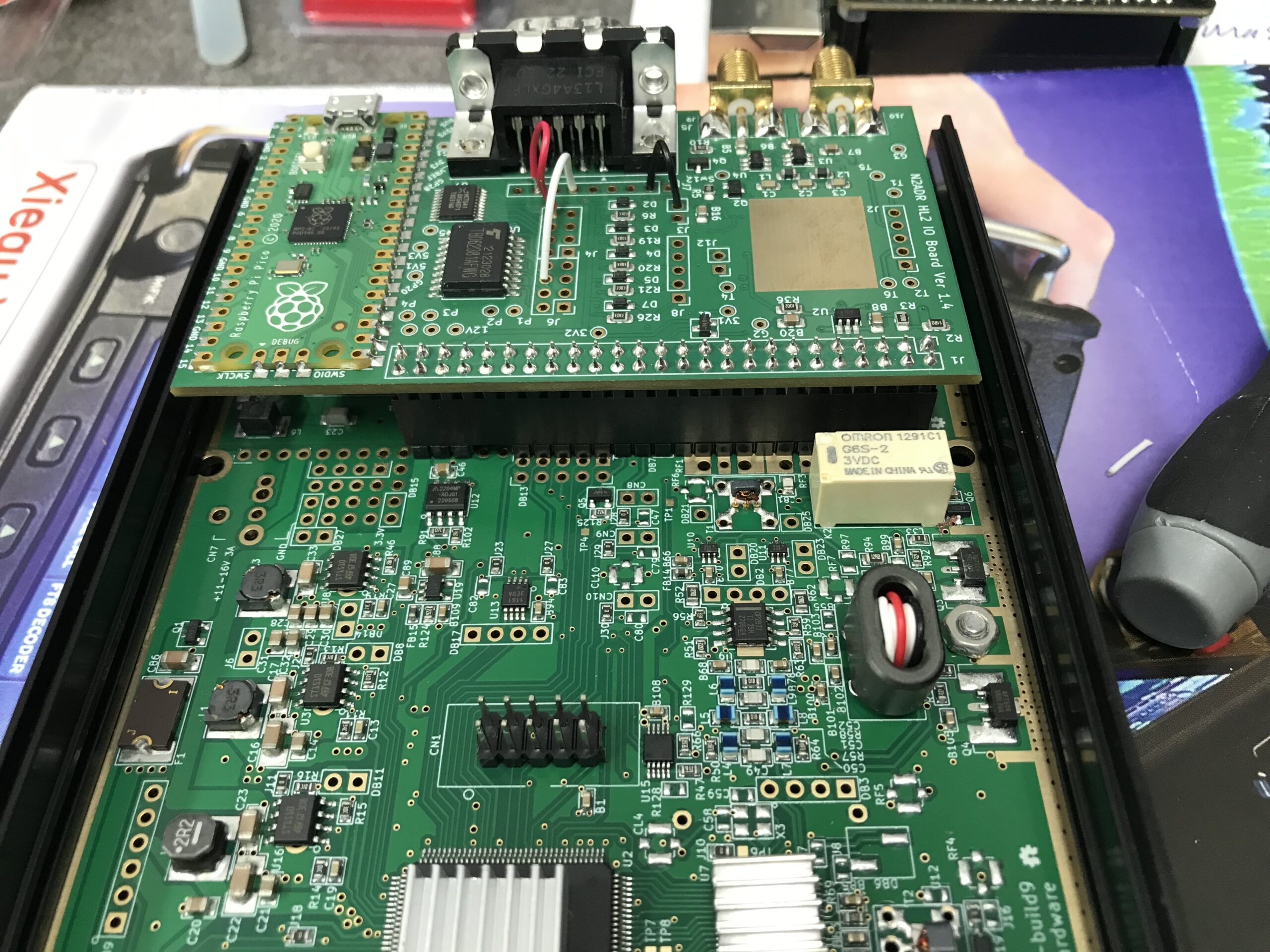
View of the fitted HL2 I/O board from above
Before the HL2 case can be put back together it’s necessary to load the software onto the RaspberryPi Pico (top left in photo above) that controls the I/O board.
This is accomplished by pressing the tiny button on the Pico whilst connecting a USB lead to the USB socket on the board that had already been plugged into my PC. Once connected the Pico appeared as a USB drive on my Kubuntu Linux desktop. All I then had to do was to copy the software file onto the drive. Once the software file is on the drive the Pico will reboot automatically and the little LED on the board will start to flash to show it has booted successfully. At this point I could safely unplug the USB cable.
The software for the RaspberryPi Pico is available for download below.
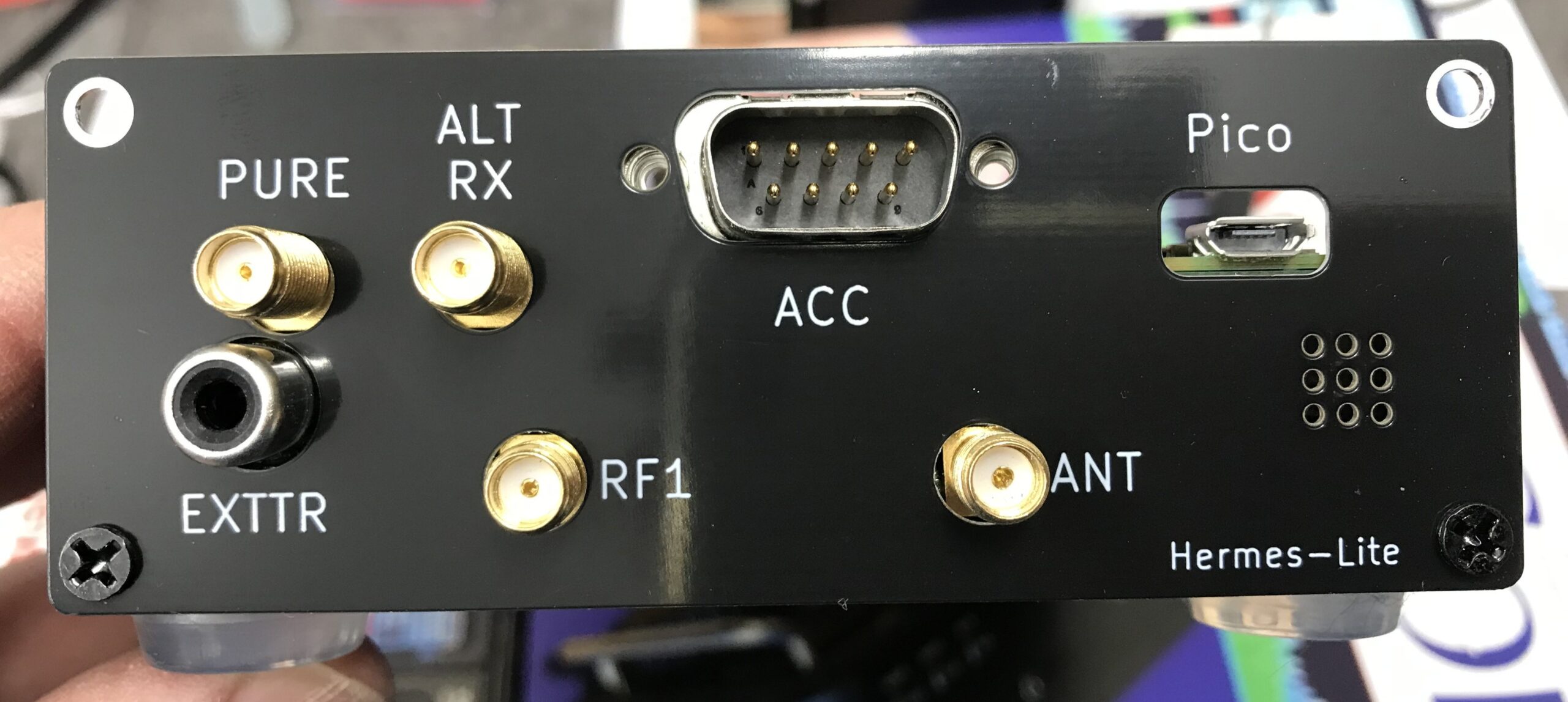
The I/O board comes with a new back panel for the HL2 to accommodate the extra connectors on the rear. Refit the top of the HL2 case and then attach the new rear panel using the original 4 counter sunk screws.
Supplied HL2 I/O board replacement rear panel fitted to the case
The final part of this project is to make the lead that will go from the HL2 rear DB9 ACC connector to the Xiegu XPA125B mini din ACC socket.
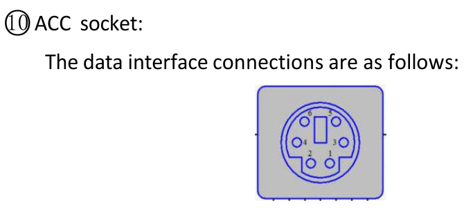
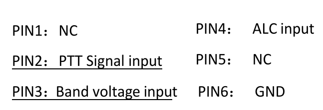
DB9 Pin 2 (BLACK) to Mini Din Pin 6 (GND)
DB9 Pin 6 (WHITE) to mini Din Pin 2 (PTT)
DB9 Pin 8 (RED) to Mini Din Pin 3 (Band Switching Voltage)
Below are a couple of screenshots from the Xiegu XPA125B user manual showing the Mini Din pin layout and the data interface connections for the amplifier.
Before I connected the lead to the two devices, I tested the end-to-end continuity of the lead to ensure all pins were correctly connected and that there were no shorts between any of the pins.
It’s important that the wires are connected to the correct pins on each end of the lead. Failure to ensure correct connection could cause damage to your HL2 and/or amplifier.
Once the lead had been tested, I connected it to both the Hermes Lite 2 and the Xiegu XPA125B amplifier. I also had to switch the amplifier band switching to AUTO.
Now when I change band on my HL2 in the PiHPSDR software the amplifier also changes band at the same time keeping the two devices in sync. No more manual band changing for me!
I hope this article is of use to other Hermes Lite 2 users who have purchased the Xiegu XPA125B but, have yet to setup auto band switching between the two devices.
Thanks to Steve, M0XVT for all the jumper information and the RaspberryPi Pico Software to get this all working.
UPDATE: The RaspberryPi Pico software originally came from Ramon, KP4RX. More information can found in this Google Groups article where he released the binary into the wild.
A full table of I/O resources available on the HL2 I/O board can be found on the KP4RX Guthub page.
The source code for the main.uf2 file above can be found at KP4RX.com
Please note: This build is now deprecated and will no longer work. Please use the new AllStarLink 3 build process as documented on the AllStarLink website.
We’ve recently added a new room to the Matrix HAM Radio Space for Digital Voice modes as this was an area of interest that didn’t really fit into any of the other rooms.
The new Digital Voice room has attracted a lot of attention from members, with a lot of the focus being on the AllStarLink system. Michael, DK1MI built an AllStarLink node in the cloud for us all to use for Matrix Nets and so I decided I had to get in on the fun.
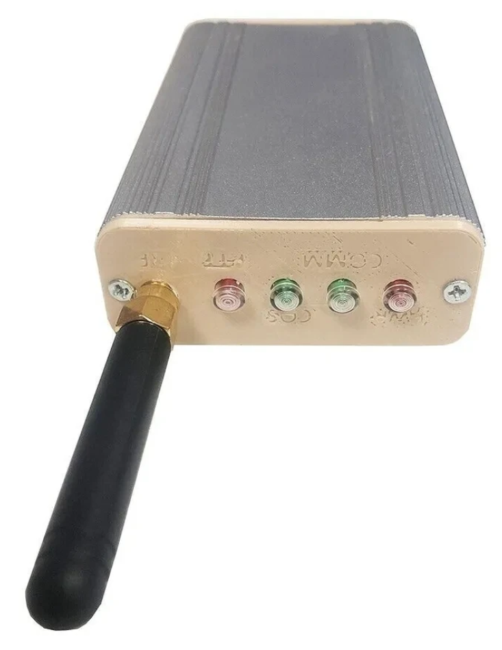
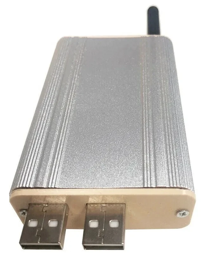
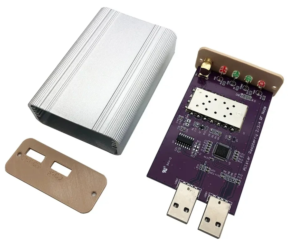
Jumbospot SHARI SA818 Amateur Radio AllStarLink Radio Interface Front Panel ViewJumbospot SHARI SA818 Amateur Radio AllStarLink Radio Interface Rear ViewJumbospot SHARI SA818 Amateur Radio AllStarLink Radio Interface stripped down View
The two USB connectors on the SHARI device are position such that they plug into two of the available 4 USB ports on the RaspberryPi without the need for cables. This keeps the whole solution together in one neat package.
Before you start you will need to obtain a node number and secret (password) from the AllStarLink Portal. To get this you will need to provide proof to the AllStarLink administrators that you are a licensed Amateur Radio (HAM) operator. This is done by uploading a copy of the first page of your HAM licence to the website for the admin team to check. This can take 24hrs to be completed so make sure you get this all done before trying to build your node. You cannot build a node successfully without a node number and secret.
Of course you will also need a transceiver that can operate on the 438.800Mhz frequency or other frequency of your choice on the 2m or 70cm HAM band.
You will also need to open port 4569 on your internet router and setup port forwarding to the IP Address that you will be using on your RaspberryPi node. It’s important to use a static IP Address on your RaspberryPi.
There are quite a few different Linux based operating system (O/S) images that are available for the RaspberryPi devices that have been specifically tailored for the AllStarLink node and include all the necessary software and library packages out the box.
Once downloaded you need to burn the ISO image onto a suitable SD card for your RaspberryPi. I use BalenaEtcher as it’s extremely quick and reliable at burning ISO images to SD cards.
Of course if you are a hardline Linux command line junkie you can always use dd to create the SD card.
Once you’ve got your O/S onto your SD card, slot it into your RaspberryPi making sure your SHARI device is connected to the two USB ports and then power it up. Make sure you have a good PSU for the RaspberryPi as the two devices together draw around 3A of current during the transmit cycle. (I use a 3.6A PSU from Amazon).
The default login for the Raspbian O/S is shown below. Login via SSH and configure your RaspberryPi for your local network. It’s important to use a static IP Address configured either directly on the RaspberryPi or via DHCP in your router.
Next you need to change directory into the asterisk config file directory using the command shown below:
cd /etc/asterisk
In this directory you will find all the default config files that come as part of the distro. For this build we’re not going to use them and so we need to move them out of the way ready for a set of config files that have already been configured correctly.
Using the following commands create a new directory, move into that new directory and then move all the unwanted configuration files into it:
mkdir ORIGINAL-CONF-FILES
cd ./ORIGINAL-CONF-FILES
mv ../*.conf ./
ls -la
cd ../
You should now be back in the /etc/asterisk directory which will now be empty apart from the custom directory which we left in place.
You now need to copy the correctly configured configuration files into the /etc/asterisk directory. Start by downloading the zip file containing the new configuration files
Download removed as deprecated.
Once downloaded, copy the .zip file into the repeater users home directory (/home/repeater) using either scp on the Linux command line or if using Windows you can use the FileZilla Client in SFTP mode using the login details above.
Once you have the .zip file in the repeater user’s home directory you need to copy the file into the /etc/asterisk directory as user root:
Next as user root, change directory into the /etc/asterisk directory and unzip the .zip file:
cd /etc/asterisk
unzip ./AllStarLink-Config-v3.zip
Once the file is unzipped you will have a directory called AllStarLink-Config in the /etc/asterisk directory. You now need to cd into the directory, copy all the files out of it into the /etc/asterisk directory leaving a copy in the AllStarLink-Config directory for future reference:
cd /etc/asterisk/AllStarLink-Config
cp ./* /etc/asterisk
cd /etc/asterisk
You now need to move a couple of files into the repeater users home directory using the following commands:
The gpioBASH script and configuration details were supplied by Mark, G1INU in the Digital Voice room on the Matrix. It adds the COS light functionality to the setup. The COS light will now light every time the SA818 hears RF on the input.
The next thing you need to do is configure the SA818 radio device in the SHARI. The script I used was originally from https://wiki.fm-funknetz.de/doku.php?id=fm-funknetz:technik:shari-sa818 all I’ve done is change the entries to switch off CTCSS and change the frequency to 438.800Mhz. Configuring the SA818 is done by running the SA818-running.pyPython programme that you moved into the repeater user home directory. Making sure you are still user root, run the following commands:
cd /home/repeater
./SA818-running.py
At this point your SHARI SA818 device will be configured to operate on 438.800Mhz and CTCSS will be disabled.
If you want to change the frequency or enable and set a CTCSS tone to access the node you will need to edit the Python programme using your favourite text editor and change the entries accordingly. Once changed rerun the program as shown above and your SHARI will be reconfigured to your new settings.
Next you need to move the allmon.ini.php file into the correct directory so that it enables access to the Allstar Monitor web page on the device so that you can manage connecting/disconnecting nodes. Use the following commands as user root to achieve this:
The allmon.ini.php file needs to have your node name entered into it to work correctly. As user root, change directory and edit the file using your favourite editor.
cd /var/www/html/allmon2
Using your text editor, search for the line starting [XXXXX] and change the XXXXX to your node number. Save the change and exit the file.
At this point you are almost complete, all that is left to do is add your node number and node secret into the appropriate configuration files in the /etc/asterisk directory.
Since I am a Linux command line junkie I use vi to edit all the configuration files on the command line as user root, but you can use any editor of your choice.
cd /etc/asterisk
Start with the extensions.conf file. Search for the line starting with NODE = and delete the XXXXX entry and insert your node number. Save the file and exit it.
Next you need to edit the iax.conf file. This time search for the line starting with register= and change the XXXXX for your node number and the YYYYYYYYYYYY for your node secret. Be careful not to accidentally delete any other characters in the lines otherwise it will corrupt the configuration file.
In the same file search for the two lines that start with secret = and change the YYYYYYYYYYYY for your node secret. Once you have changed both of the secret entries, save and exit the file.
The final file to edit is the rpt.conf file. Once again open the file using your favourite editor and search for the line starting with XXXXX = radio@127.0.0.1:4569/XXXXX, change the XXXXX entries for your node number making sure not to delete any other characters next to the XXXXX entries.
Further down in the same file there is a line that starts with [XXXXX], once again change the XXXXX for your node number making sure to keep the square brackets at each end of the node number as you edit it.
Finally move down to the very bottom of the file and find the two lines that start with /home/repeater/gpio, once again change the XXXXX entries for your node number.
The final thing to change in the rpt.conf file is to replace my callsign with your own callsign so that the node identifies itself correctly. Scroll through the file until you find the two lines shown below, delete M0AWS and add your own callsign instead making sure you keep all the spaces between words as shown below.
idrecording = |i DE M0AWS
idtalkover = |i DE M0AWS
Once this is done, save and exit the file. At this point your node should be fully configured and will only require a reboot to get it working.
As user root, reboot your raspi using the reboot command.
reboot
Once your raspi comes back online, login using SSH as user repeater and then become root user using the sudo command detailed above.
You now need to create the admin user password for the Allstar Monitor web page on the device. This is done using the following commands as user root:
cd /var/www/html/allmon2
htpasswd -c .htpasswd admin
You will be asked to enter a password twice for the admin user. Make sure you make a note of this user/password as you will need it to login to the web page.
Finally check that the controlpanel.ini.php file is in the /var/www/html/allmon2 directory:
ls -la /var/www/html/allmon2/controlpanel.ini.php
If the file isn’t shown in the directory, enter the following commands to create the file in the correct place as user root and then exit the SSH session:
cd /var/www/html/allmon2
cp ./controlpanel.ini.txt ./controlpanel.ini.php
cd
exit
Once this is done your configuration is complete, logout from the terminal session by entering exit once more and your SSH session will terminate.
Using your favourite web browser enter the IP Address of your raspi into the URL bar as shown below:
http://<Your-Raspi-IP>/allmon2
Note: remove the <> from the URL once you have entered the required information.
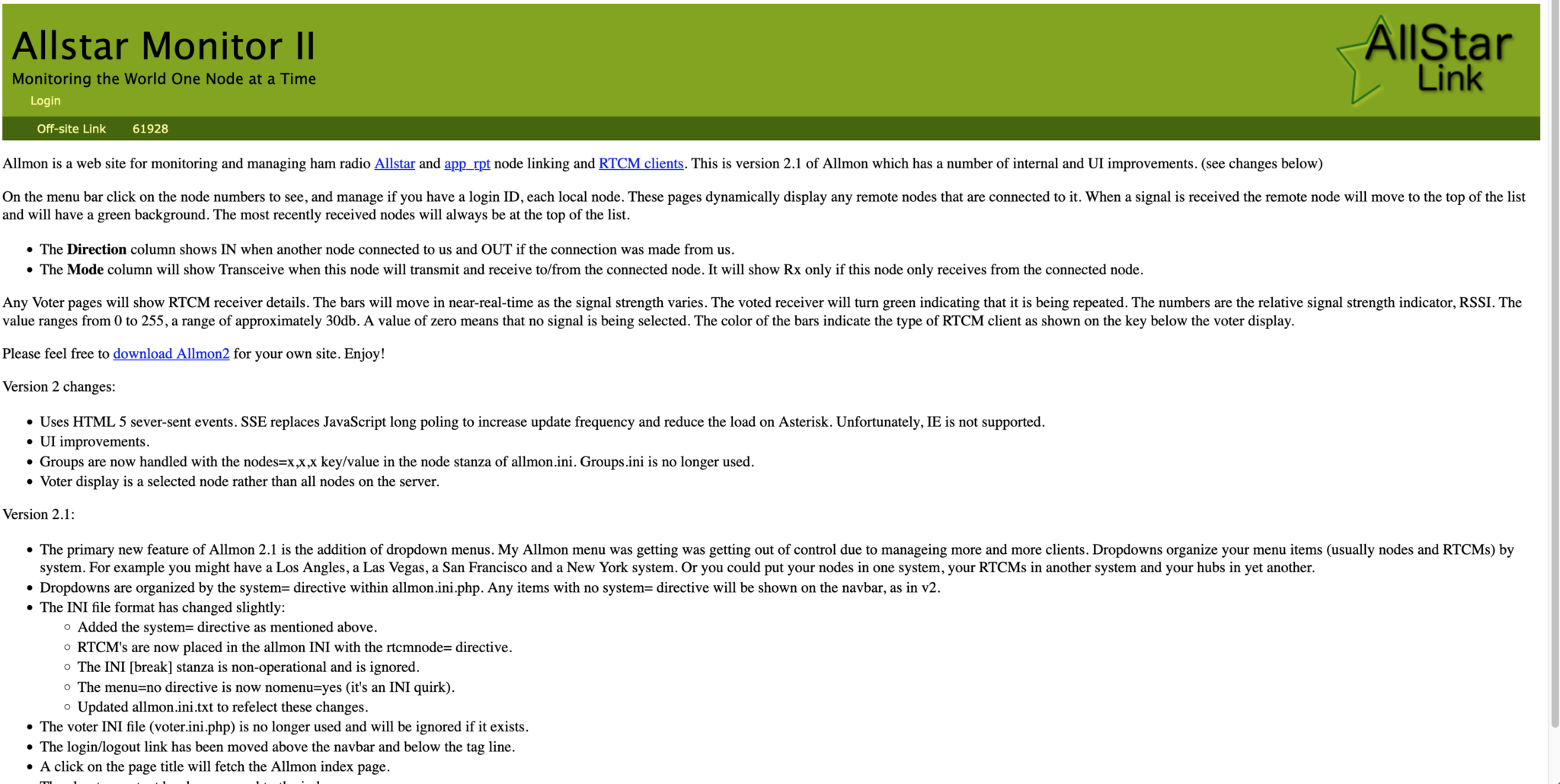
Once this is done you should be presented with your node control panel as shown below.
First visit to the AllStar Monitor Web Page
Login using Admin and the password you set above and you are now ready to start using your node.
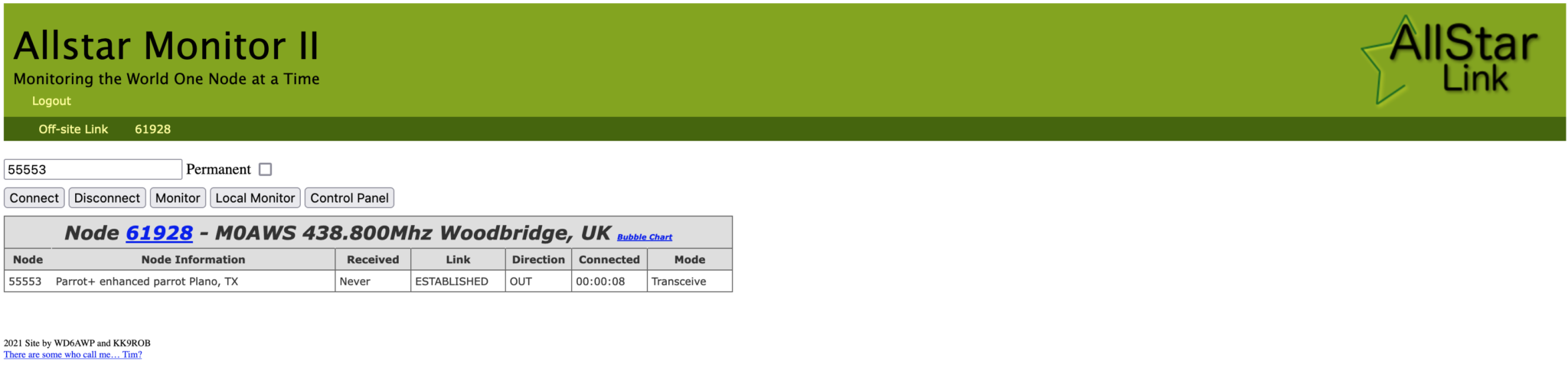
It’s a good idea to connect to node 55553 which is a parrot test node to check your audio levels. You can do this by entering the node into the field at the top left and pressing the connect button.
M0AWS AllStarLink Node 61928 connected to 55553 Parrot
Once connected, tune your radio to 438.800Mhz FM and transmit a test message using your callsign and test123, or something similar. The parrot will then play your recording back to you so that you can hear how you sound. It will also comment on your audio level as to whether it is OK or not.
You are now connected to AllStarLink network and have the world at your finger tips. Below is a small list of nodes in the UK, Australia and America to get you started chatting with other HAMs via your node.
57881	Matrix HAM Radio Space AllStarLink Node (Hosted by Dk1MI)
55553	ASL Parrot for testing
41522	M0HOY HUBNet Manchester, UK
60349	VK6CIA 439.275 Perth, Western Australia
51077	VK6SEG South West Hub B Albany WA
2167	M0JKT FreeSTAR UK HUB 2 freestar.network
53573	NWAG NW AllStar Group Lancashire, UK
27339	East Coast Hub Wilmington NC USA
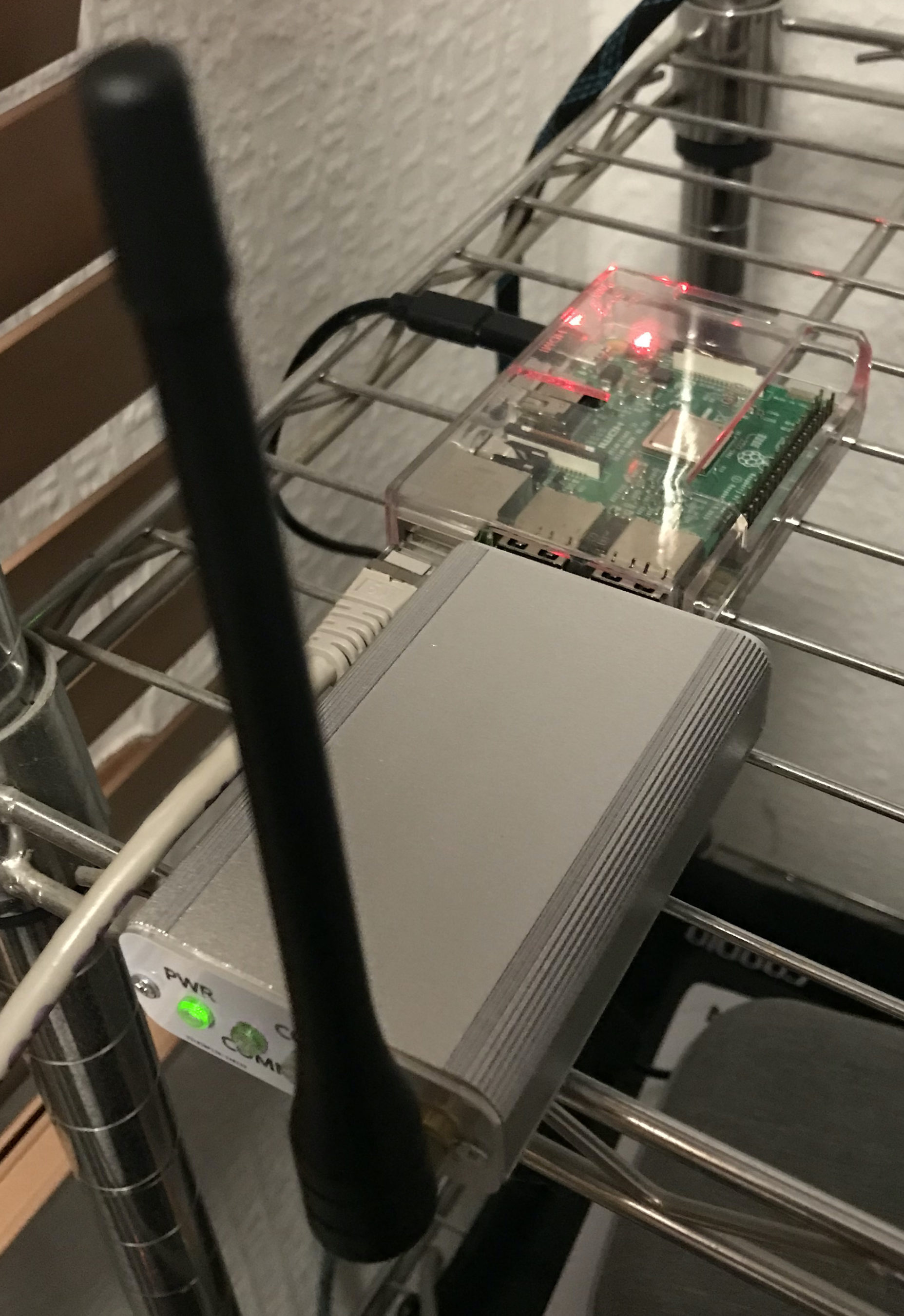
M0AWS AllStarLink Node 61928 sitting on the equipment rack
Thanks to Michael, DK1MI for building and hosting the Matrix HAM Radio Space AllStarLink Node (57881) and getting us all started in the world of AllStarLink!
We hope to be having regular Matrix Net’s on the node soon for all Matrix members and visitors. We’ll organise days/times via the Digital Voice room.
A couple of years ago I built a Matrix Synapse server and connected it to the decentralised global Matrix chat network that is federated world wide by enthusiasts who host their own Matrix servers. Due to the enthusiasm for a decentralised network the Matrix has grown exponentially and is now an established force in the world of Opensource global communication services.
When I built my server and configured it online my aim was to bring together an enthusiastic group of Radio Amateurs (Radio HAMs) who could build a friendly, welcoming community where people could share, learn and have fun with other liked minded individuals without all the nonsense you see on commercial social media platforms.
Overtime we’ve increased the number of rooms available in the HAM Radio space and the number of subjects covered. This has grown organically as our community has grown and we’ve ventured together into new areas of the hobby.
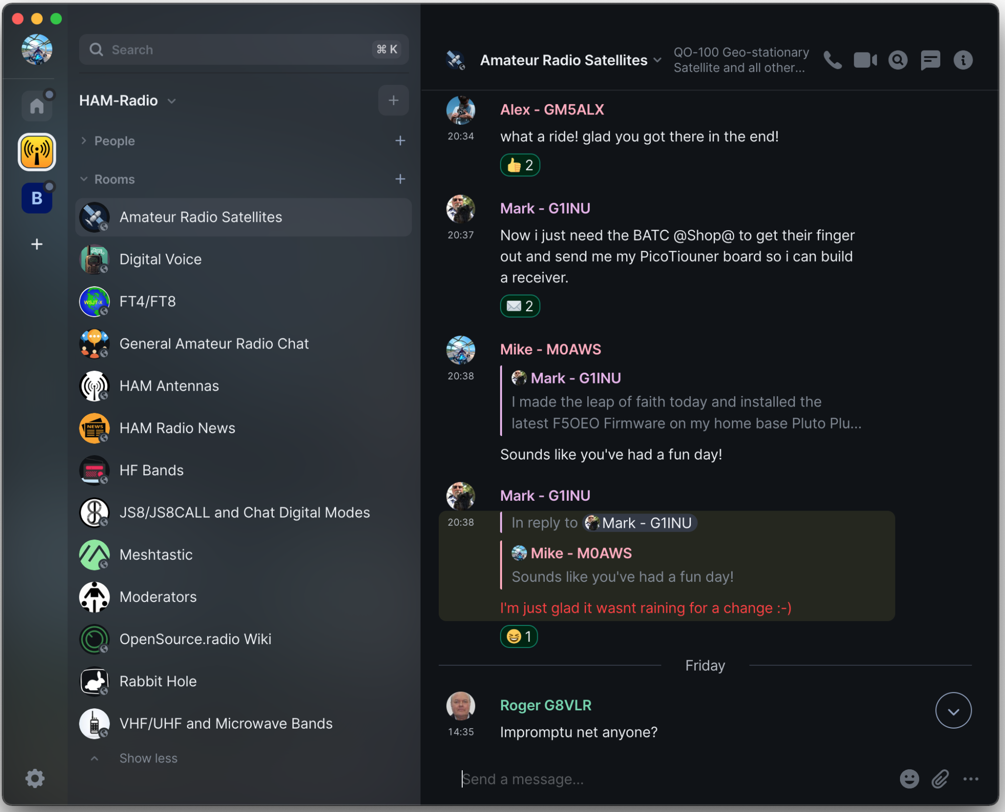
Global Matrix Ham Radio Space hosted on the M0AWS Matrix Server
From the community a number of projects have spawned including the Opensource.radio Wiki that Mike, DK1MI is sponsoring that aims to detail all the Opensource HAM Radio software, Hardware and projects in one centralised site on the internet. This is a great project and one I am very happy to contribute to.
Thanks to Mike, DK1MI we now also have our own Matrix AllStarLink node available. This is a great resource for the community as it is often not possible for all of us to communicate via the radio waves due to geo-location, time zones, local planning regulations etc. Having this 24/7 internet based resource makes it a lot easier for the community to chat at any time even when propagation on the HF bands isn’t in our favour.
We also have a very active satellite room with regular nets on the QO-100 satellite. With such a great range of rooms and subjects there’s plenty to read and talk about with the community.
If you fancy being part of this growing, enthusiastic group of Radio Amateurs and Short Wave Listeners (SWLs) then click on the link below and come and say hello, a warm welcome awaits!
We use cookies to ensure that we give you the best experience on our website. If you continue to use this site we will assume that you are happy with it.