FreeDV audio routing with PiHPSDR and Hermes Lite 2

I’ve recently been trying out the FreeDV RADEv1 digital voice mode on the HF bands with great success. The audio quality is astounding when compared to the normal analog SSB mode. Using only 20w I’ve been surprised how successful I’ve been talking to stations in the UK and Europe as can be seen in my FreeDV Log.

FreeDV has been around for quite a few years with development being funded by an ARDC grant and financial sponsorship from the Software Freedom Conservancy.

So what is FreeDV?

To quote the FreeDV website:

FreeDV is a suite of digital voice modes for HF radio. Our flagship mode is the Radio Autoencoder (RADE). You can run RADE using a free GUI application for Windows, Linux and macOS that allows any SSB radio to be used for high quality digital voice.

And the most important part:

All software is open source, released under the (a) GNU Lesser Public License version 2.1 (GUI and legacy FreeDV modes) and two-clause BSD license (RADE).

FreeDV running under KDE-Plasma on Kubuntu PC

Looking at the digital voice (DV) community in the HAM Radio world, it’s stuffed full with proprietary DV modes from small software houses and black box transceiver manufacturers with no real OpenSource alternatives, until now.

Installing FreeDV is pretty simple regardless of which operating system (O/S) you use. Being a Linux user I grabbed the AppImage from the website and set about reading up on how it works and how it is configured.

I decided to take the two sound card approach since I have 2 USB sound cards connected to my shack Kubuntu Linux PC.

Configuring the audio routing isn’t straight forward as both the receive and transmit audio to/from the radio needs to be routed via the FreeDV app. To make this even more complicated I am using my Hermes Lite 2 SDR transceiver and PiHPSDR software, a complete OpenSource/OpenHardware Amateur Radio Station.

M0AWS FreeDV and PiHPSDR Audio Routing Diagram

Trying to clearly describe the audio routing using words alone would be impossible and very confusing so, I put together the diagram above.

Using two USB sound cards I’ve configured the system such that USB Sound Card 1 (an old Griffin iMic USB sound device) handles just the audio from/to the headphones and microphone. All the audio at this point in the system is analogue.

The second USB sound card, a cheap Plug and Play (PNP) USB audio device from Amazon, handles all the digitised signals from/to FreeDV and PiHPSDR.

Taking this 2 sound card approach keeps confusion to a minimum and separates the analogue and digital components of the audio routing.

So, how does this translate to the FreeDV and PiHPSDR audio settings?

Transmit Audio Chain

FreeDV Transmit Audio Settings

Starting at the beginning of the transmit audio chain, let’s look at the transmit audio settings in FreeDV.

Looking at the FreeDV Transmit audio settings screenshot below we can see that the
Input From Microphone to Computer device is set to:

alsa_input.usb-Griffin_Technology_Inc_iMic_USB_audio_system-00.analog-stereo

This is the microphone connection on the iMic USB device (USB Sound Card 1) and is the analogue transmit audio input to FreeDV.

The Output From Computer to Radio device is set to:

alsa_output.usb-0c76_USB_PnP_Audio_Device-00.analog-stereo

This is the digitised audio output from FreeDV (via USB Sound Card 2) to PiHPSDR and is used as the transmit audio that is sent to the Hermes Lite 2 transceiver.

FreeDV Transmit Audio Settings

PiHPSDR Transmit Audio Setting

To complete the transmit audio path we next need to look at the PiHPSDR transmit audio setting.
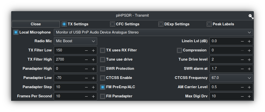
PiHPSDR Transmit Audio Settings

As can be seen in the screenshot above, the Local Microphone device in PiHPSDR is set to the Monitor of USB PnP Audio Device Analogue Stereo.

This effectively routes the digitised output audio from FreeDV (Output From Computer to Radio device) to the Input audio of PiHPSDR.

The reason for using the Monitor audio feed is because FreeDV does not recognise the Mic Input in PiHPSDR as a valid output device for FreeDV to use, hence we just need to monitor the FreeDV output device and use it as our input audio device in PiHPSDR.

This completes the transmit audio chain.

Receive Audio Chain

PiHPSDR Receive Audio Setting

Starting at the beginning of the receive audio chain we first look at the PiHPSDR receive audio setting.

PiHPSDR Receive Audio Setting

In the screenshot above we can see that the receive audio output from PiHPSDR is set to
USB PnP Audio Device Analogue Stereo (USB Sound Card2). This is the DX station’s digitised audio as received by the Hermes Lite 2.

FreeDV Receive Audio Settings

Next let’s look at the receive audio setting in FreeDV.

FreeDV Receive Audio Settings

The Input To Computer from Radio device is set to the monitor of the
USB PnP Audio Output Device:

alsa_output_usb_0c76_USB_PnP_Audio_Device-00.analog-stereo.monitor

This effectively routes the digitised audio output from the PiHPSDR receiver to the digitised audio input of FreeDV.

Once again we have to use the monitor of the USB PnP Audio Output device as FreeDV does not recognise the PiHPSDR output as a valid input device.

Next, the Output From Computer To Speaker/Headphones device is set to:

alsa_output.usb-Griffin_Technology_Inc_iMic_USB_audio_system-00.analog-stereo

This is the analogue audio output on the iMic USB Sound card (Sound Card 1) that routes the analogue audio to the headphones and completes the receive audio chain.

Summary

The audio routing required by FreeDV can appear very daunting when first attempting to configure it on the Linux platform but, hopefully the diagram and screenshots above will help in understanding the complete end-to-end audio chain that is required to make this mode work.

PiHPSDR can of course be replaced by your black box radio CODEC entries that will appear in the device lists shown above if you have your radio connected via USB. The config is basically the same but, just uses a different device instead of USB sound card 2 shown in the diagram above.

I hope this article is useful to those wanting to try FreeDV on the Linux platform and I look forward to hearing you on RADEv1.

More soon …
Deep Dive – Node-RED QO-100 Satellite Ground Station Dashboard

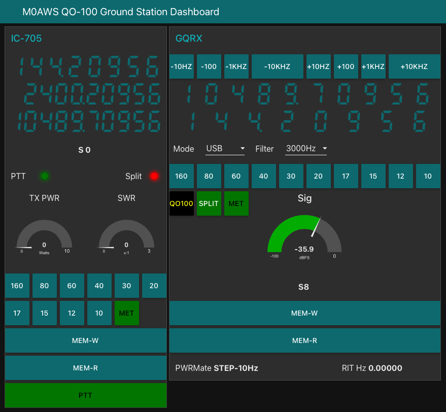
Following on from my article about my QO-100 Satellite Ground Station Complete Build, this article goes into some detail on the Node-RED section of the build and how I put together my QO-100 Satellite Ground Station Dashboard web app.

The Node-RED project has grown organically as I used the QO-100 satellite over time. Initially this started out as a simple project to synchronise the transmit and receive VFO’s so that the SDR receiver always tracked the IC-705 transmitter.

Over time I added more and more functionality until the QO-100 Ground Station Dashboard became the beast it is today.

M0AWS QO-100 ground Station Control Dashboard built using Node-RED.
M0AWS QO-100 Ground Station Control Dashboard built using Node-RED.

Looking at the dashboard web app it looks relatively simple in that it reflects a lot of the functionality that the two radio devices already have in their own rights however, bringing this together is actually more complicated than it first appears.

Starting at the beginning I use FLRig to connect to the IC-705. The connection can be via USB or LAN/Wifi, it makes no difference. Node-RED gains CAT control of the IC-705 via XMLRPC on port 12345 to FLRig.

To control the SDR receiver I use GQRX SDR software and connect to it using RIGCTL on GQRX port 7356 from Node-RED. These two methods of connectivity work well and enables full control of the two radios.

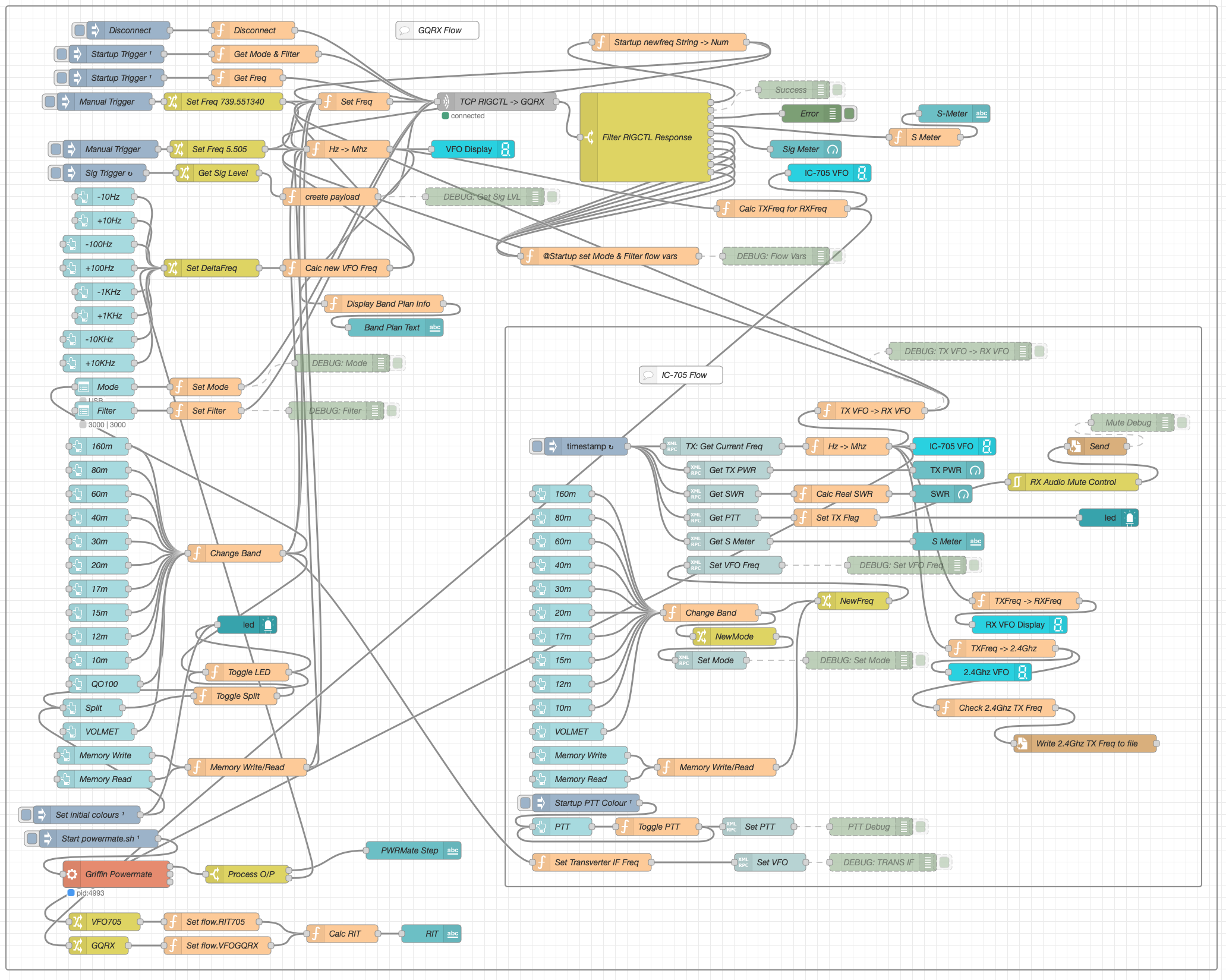
M0AWS Node-RED QO-100 Ground Station Dashboard - 12/06/24
M0AWS Node-RED QO-100 Ground Station Dashboard Flow as of 12/06/24

The complete flow above looks rather daunting initially however, breaking it down into its constituent parts makes it much easier to understand.

There are two sections to the flow, the GQRX control which is the more complex of the two flows and the comparatively simple IC-705 section of the flow. These two flows could be broken down further into smaller flows and spread across multiple projects using inter-flow links however, I found it much easier from a debug point of view to have the entire flow in one Node-RED project.

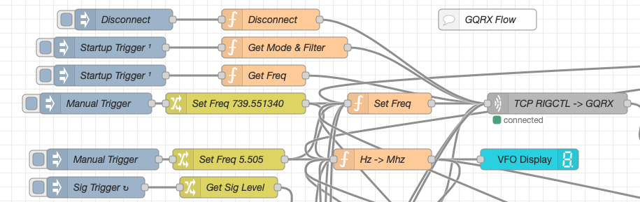
Breaking down the flow further the GQRX startup section (shown below) establishes communication with the GQRX SDR software via TCP/IP and gets the initial mode and filter settings from the SDR software. This information is then used to populate the dashboard web app.

M0AWS - Node-RED QO-100 Ground Station Dashboard - GQRX Startup
M0AWS Node-RED QO-100 Ground Station Dashboard – GQRX Startup Flow

The startup triggers fire just once at initial startup of Node-RED so it’s important that the SDR device is plugged into the PC at boot time.

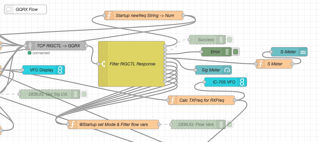
All the startup triggers feed information into the RIGCTL section of the GQRX flow. This section of the flow (shown below) passes all the commands onto the GQRX SDR software to control the SDR receiver.

M0AWS - QO-100 Ground Station Dashboard - GQRX RIGCTL flow
M0AWS Node-RED QO-100 Ground Station Dashboard – GQRX RIGCTL Flow

The TCP RIGCTL -> GQRX node is a standard TCP Request node that is configured to talk to the GQRX software on the defined IP Address and Port as configured in the GQRX setup. The output from this node then goes into the Filter RIGCTL Response node that processes the corresponding reply from GQRX for each message sent to it. Errors are trapped in the green Debug node and can be used for debugging.

The receive S Meter is also driven from the the output of the Filter RIGCTL Response node and passed onto the S Meter function for formatting before being passed through to the actual gauge on the dashboard.

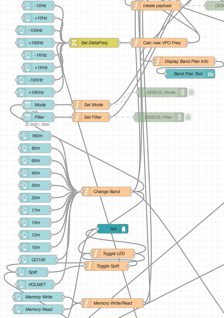
Continuing down the left hand side of the flow we move into the section where all the GQRX controls are defined.

M0AWS - QO-100 Ground Station Dashboard - GQRX Controls
M0AWS Node-RED QO-100 Ground Station Dashboard – GQRX Controls Flow

In this section we have the VFO step buttons that move the VFO up/down in steps of 10Hz to 10Khz. Each button press generates a value that is passed onto the Set DeltaFreq change node and then on to the Calc new VFO Freq function. From here the new VFO frequency is stored and passed onto the communications channel to send the new VFO frequency to the GQRX software.

The Mode and Filter nodes are simple drop down menus with predefined values that are used to change the mode and receive filter width of the SDR receiver.

Below are the HAM band selector buttons, each of these will use a similar process as detailed above to change the VFO frequency to a preset value on each of the HAM HF Bands.

The QO-100 button puts the transmit and receive VFO’s into synchro-mode so that the receive VFO follows the transmit VFO. It also sets the correct frequency in the 739Mhz band for the downlink from the LNB in GQRX SDR software and sets the IC-705 to the correct frequency in the 2m VHF HAM band to drive the 2.4Ghz up-converter.

The Split button allows the receive VFO to be moved away from the transmit VFO for split operation when in QO-100 mode. This allows for the receive VFO to be moved away so that you can RIT into slightly off frequency stations or to work split when working DXpedition stations.

The bottom two Memory buttons allow you to store the current receive frequency into a memory for later recall.

At the top right of this section of the flow there is a Display Band Plan Info function, this displays the band plan information for the QO-100 satellite in a small display field on the Dashboard as you tune across the transponder. Currently it only displays information for the satellite, at some point in the future I will add the necessary code to display band plan information for the HF bands too.

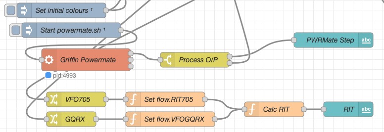
The final section of the GQRX flow (shown below) sets the initial button colours and starts the Powermate USB VFO knob flow. I’ve already written a detailed article on how this works here but, for completeness it is triggered a few seconds after startup (to allow the USB device to be found) and then starts the BASH script that is used to communicate with the USB device. The output of this is processed and passed back into the VFO control part of the flow so that the receive VFO can be manually altered when in split mode or in non-QO-100 mode.

M0AWS - QO-100 Ground Station Dashboard - Powermate VFO section
M0AWS Node-RED QO-100 Ground Station Dashboard – Powermate VFO Flow

The bottom flows in the image above set some flow variables that are used throughout the flow and then calculates and sets the RIT value on the dashboard display.

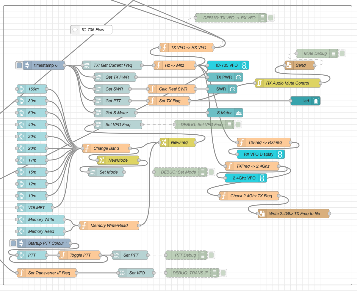
The final section of the flow is the IC-705 control flow. This is a relatively simple flow that is used to both send and receive data to/from the IC-705, process it and pass it on to the other parts of the flow as required.

M0AWS - QO-100 Ground Station Dashboard - IC-705 control flow
M0AWS Node-RED QO-100 Ground Station Dashboard – IC-705 Control Flow

The IC-705 flow is started via the timestamp trigger at the top left. This node is nothing more than a trigger that fires every 0.5 seconds so that the dashboard display is updated in near realtime. The flow is pretty self explanatory, in that it collects the current frequency, transmit power, SWR reading, PTT on/off status and S Meter reading each time it is triggered. This information is then processed and used to keep the dashboard display up to date and to provide VFO tracking information to the GQRX receive flow.

On the left are the buttons to change band on the IC-705 along with a button to tune to the VOLEMT on the 60m band. Once again there two memory buttons to save and recall the IC-705 VFO frequency.

The Startup PTT Colour trigger node sets the PTT button to green on startup. The PTT button changes to red during transmit and is controlled via the Toggle PTT function.

At the very bottom of the flow is the set transverter IF Freq function, this sets the IC-705 to a preselected frequency in the 2m HAM band when the dashboard is switched into QO-100 mode by pressing the QO-100 button.

On the right of the flow there is a standard file write node that writes the 2.4Ghz QO-100 uplink frequency each time it changes into a file that is used by my own logging software to add the uplink frequency into my log entries automatically. (Yes I wrote my own logging software!)

The RX Audio Mute Control filter node is used to reduce the receive volume during transmit when in QO-100 full duplex mode otherwise, the operator can get tongue tied hearing their own voice 250ms after they’ve spoken coming back from the satellite. This uses the pulse audio system found on the Linux platform. The audio is reduced to a level whereby it makes it much easier to talk but, you can still hear enough of your audio to ensure that you have a good, clean signal on the satellite.

As I said at the beginning of this article, this flow has grown organically over the last 12 months and has been a fun project to put together. I’ve had many people ask me how I have created the dashboard and whether they could do the same for their ground station. The simple answer is yes, you can use this flow with any kind of radio as long as it has the ability to be controlled via CAT/USB or TCP/IP using XMLRPC or RIGCTL.

To this end I include below an export of the complete flow that can be imported into your own Node-RED flow editor. You may need to make changes to it for it to work with your radio/SDR but, it shouldn’t take too much to complete. If like me you are using an IC-705 and any kind of SDR controlled by GQRX SDR software then it’s ready to go without any changes at all.


More soon …