I’ve recently built a new AllStarLink (ASL) node for my MB7IBW gateway that I have recently brought up on air on the 2m band.
AllStarLink 3 has a lot of changes in it when compared to the previous version and this of course impacts my Node-Red Control Dashboard that I’ve been using to manage my first ASL node for well over a year now.
To build the node I used the RaspberryPi imager and added the AllStarlink 3 image as detailed on the allstarlink.org website.
Installing the system this way makes it pretty easy compared to previous installs but, it comes with some quirks which cause issues with Node-Red.
From the outset the plan has always been to have AllStartLink 3 and Node-Red running on the same Pi4 to keep it totally self contained. This was easy enough to achieve and works without issue.
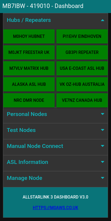
Node-Red Control Dashboard for AllStarLink 3
Installing Node-Red onto a Pi4 is really easy and is fully documented on the Node-Red Website.
Once the AllStarLink 3 operating system was installed on my SD card, booted and operational I installed Node-Red. I soon realised that there were a few things I had to do before loading the Node-Red flow.
AllStarLink 3 no longer logs connect and disconnect messages in the connectlog like it did in AllStarLink 2. To get logging working again I had to create two new BASH scripts as detailed below and put them into /etc/asterisk/myscripts.
For the connect information I created the BASH script as detailed below.
Next I disabled the temporary filesystems that are used by default for the apache and asterisk logging as it’s useful to keep the apache logs for debugging and I needed the asterisk logs for the Node-Red dashboard.
Disabling the temporary file system is very easy to do, just edit the /etc/fstab and comment out the two lines as shown below.
# Comment out the next line for persistent Apache logs
#tmpfs  /var/log/apache2        tmpfs   defaults,noatime,nosuid,nodev,noexec,mode=0775,size=32M 0 0

# Comment out the next line for persistent Asterisk logs
#tmpfs  /var/log/asterisk       tmpfs   defaults,noatime,nosuid,nodev,noexec,mode=0775,size=32M,uid=102,gid=106 0 0

# Note: These lines are wrapped, should be on 1 line in the /etc/fstab
Once the entries in the /etc/fstab were commented out I rebooted the Pi4 to get persistent filesystems.
The final thing that had to be done was to allow user repeater to use sudo without a password so that it could be used to perform reboot/shutdown/process restart as user root from within the dashboard.
# /etc/sudoers

# Allow repeater sudo without password
repeater ALL=(ALL) NOPASSWD: ALL
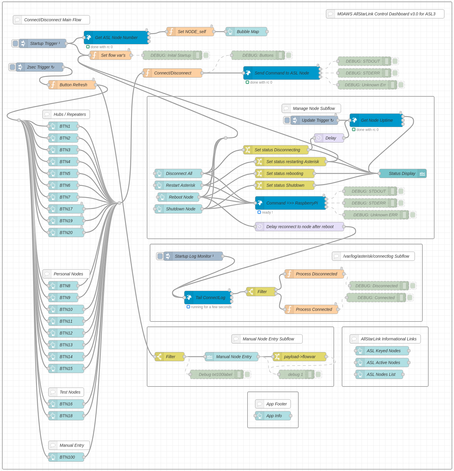
Once this was all done I imported the Node-Red flow, configured the SSH nodes with login credentials for the Pi4 (important to use the user repeater for SSH), clicked deploy and the dashboard was ready for use.
Node Red AllStarLink3 Control Dashboard Flow
I’ve been using the dashboard for a few weeks now and it’s running perfectly, without error.
If you want to build your own Node-Red Control Dashboard for your AllStarLink 3 node then, just download the flow using the button below and import it into your flow editor.
I’ve not written an article on the blog for a while now mainly because I’ve not had anything interesting to write about.
Today that changed, as I had a fun little project to dive into.
Steve, M0XVT sent me his Pluto+ SDR transceiver after his rather unsuccessful attempt at updating the firmware. Long story short, he somehow managed to brick the Pluto+ rendering it completely useless.
Not having a Pluto+ myself I’ve never actually played with one before and so this was new and exciting. I have, however played with Steve’s LibreSDR which is a later iteration of the Pluto+ and so, I had an idea of what I was getting into.
Firstly, how do you know when you have bricked your Pluto+?
Fortunately the Pluto+ device is actually quite clever and will inform you when it is bricked. The first sign you will notice is that you can no longer connect to the device using a USB connection to the data socket. The second sign is that when you take the top off the case you’ll notice that the blue LED is off and the green LED is on constantly. These are both classic signs that the device is bricked and needs rescuing
So, how do we rescue a bricked Pluto+?
Firstly, disconnect all cables and power to the device, it needs to be in a powered down state. Next remove the top of the case completely.
Unlike the LibreSDR the Pluto+ doesn’t boot from SD card so, we have to tell it that we want to boot it from an SD card. This is done by shorting the 3v3 and SD-H pins together using a jumper as shown in the photo below. (Black Jumper)
Pluto+ 3v3 and SD-H pins shorted together by black jumper
I believe that the v1 version of the Pluto+ has 1.8v instead of 3.3v, if this is the case on your device just short the SD-H pin to the 1v8 pin instead.
Next we need to make sure that the URST pin is connected to the MIO46 pin as shown by the green jumper in the image above. I put the jumper into this position as I am going to be using firmware that has ethernet support built in. If you want to load the official firmware then you will need to connect the URST pin to the MIO52 pin instead.
Next we need to load the new firmware onto an appropriate SD card. I’m using the F5OEO firmware that has ethernet support with DHCP built in. You can get the firmware from this Github link.
Whilst the firmware is downloading, insert your SD card into your PC and format it using a FAT32 filesystem.
Once the firmware has downloaded, unzip the file and save the contents of the zip file to a directory. Using your favourite file manager or in the case of a Linux junkie like me, the command line, copy the contents of the sdimg folder into the root of the SD card.
Note: That’s copy of the contents of the sdimg folder, not the folder itself.
Make sure to eject your SD card safely before removing it from your PC to ensure you don’t corrupt the contents.
Insert the SD card into the Pluto+ (it’s still powered down at this point with the top off).
Plug the USB A end of the USB cable into your PC but, do not plug the micro USB end into the Pluto+ just yet!
Now this is the tricky part, you need to hold down the DFU Button on the Pluto+ PCB (It’s behind the professor image on the PCB) whilst inserting the micro-USB plug into the DATA port of the Pluto+.
Once you see that the green and blue LED lights come on permanently, let go of the DFU Button and let the Pluto+ boot from the SD card. A short while afterwards the green LED should start flashing, this means your Pluto+ is alive again and has booted from the SD card.
At this point it’s important not to unplug the USB cable and not to remove the SD card from the device, we’re only half way there!
After a little more time the Pluto+ will appear in your file manager as a drive called PlutoSDR, navigate to this drive using your favourite file manager.
At the same time, open another window in your file manager and navigate to the folder where you saved the files from the Zip file. In this directory you will see the following two files:
boot.frm
pluto.frm
Copy these two files from the directory where you saved them into the root of the PlutoSDR drive.
Once this is complete, eject the PlutoSDR drive safely.
The green LED will now start blinking, don’t do anything, just leave everything as it is and the device will now create a new boot image on it’s own built in storage.
This process will take about 5mins so, go grab a cold beer, glass of wine or anything else that takes your fancy, sit back and relax.
Eventually the green LED will stop flashing, wait another minute or so for the process to fully complete.
If the PlutoSDR drive has reappeared in your file manager, safely remove the drive from your file manager and unplug the micro USB connector from the Pluto+ powering it down.
It’s now important to remove the 3v3 to SD-H jumper as we no longer need to boot from SD card.
You can now refit the top cover and the 4 screws and put the case back together. Connect an ethernet cable and micro USB cable to the DATA port and wait.
After about 10-15 seconds the green LED should flash and your Pluto+ is now no longer bricked and ready for use once more.
You can SSH to your Pluto+ using the normal Linux SSH command logging in as root with a password of analog.
If you have PiHPSDR installed and compiled with the SOAPYSDR library and modules (See my article on how to do this easily) you can now start it and connect to your Pluto+ device as normal.
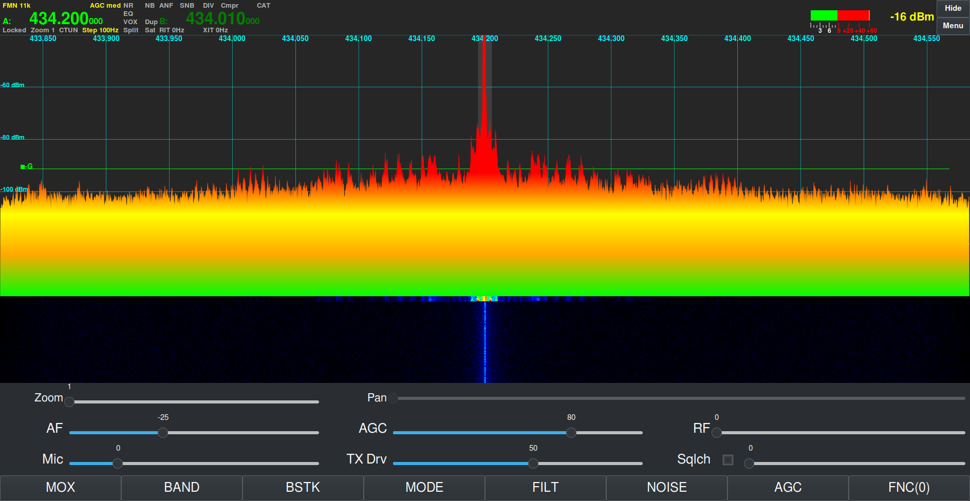
Steve’s rescued Pluto+ receiving a signal on the 70cm band
This same procedure can be used on Linux, Mac, Windows and RaspberryPi, it is not platform dependent.
If you want your Pluto+ to always boot from the SD card, you can leave the 3v3 pin connected to the SD-H pin permanently.
Regular readers of my blog will already know that I am a huge fan of the Linux operating system, it’s clearly evident in most of the content on this website.
I am also a very enthusiastic user of one of the first credit card sized computers that came to be, namely the RaspberryPi. I own all the iterations of this wonderful little computer from the very first version to the latest and greatest, RaspberryPi 5.
This little computer has done more for computing in education than Microsoft and Apple will ever achieve and it’s done it at an incredibly low price making it more accessible to schools, colleges and students than any other platform.
The RaspberryPi has what most consider to be the best support on the planet when it comes to single board computers (SBCs). From the dedicated team that build Raspberry Pi OS, to all the amazing projects and forums that are available, for free on the internet today.
The RaspberryPi computer really has revolutionised computing for the masses.
My RaspberryPi 5 that I am using to write this article.
Raspberry Pi OS really is very good. It’s based on the great Debian distro’ that many of us seasoned Linux users dearly love. It’s light weight, fast and meets the needs of everyone that is venturing into the exciting world of Linux and SBCs for the first time.
Overtime as we all become more experienced with Linux on the RaspberryPi we become more demanding and start to find the Raspberry Pi OS desktop environment lacking. Sure it can be enhanced by adding more and more to it however, it never quite reaches the point of satisfaction and we are always wishing for something more.
With the Pi-5, the latest iteration of this great credit card sized computer, users are now able to seriously think about building a more powerful desktop environment for their little berry flavoured computers.
On my desktop PCs dotted around the house I have used Kubuntu for decades. It’s a slick and powerful desktop environment that has met my needs for many years and I love it more than any other Linux desktop. Sadly Kubuntu isn’t easily available out the box for the RaspberryPi and so I decided that it was time to replicate it as closely as possible on my new, super powerful RaspberryPi 5.
When I ordered my RaspberryPi 5 from Pimoroni I added the NVMe base and 250GB M.2 SSD drive to the order. Up until now I’d always used SD cards however, they are slow and unreliable and so I decided that since the Pi-5 has PCIe it was time to take the step away from SD cards and start using SSD technology.
Getting the OS onto the SSD is a two stage affair. First you have to create a bootable SD card to boot the Pi-5 from and then use it via the RaspberryPi Imager to install the OS onto the SSD. It’s a bit long winded but, easy enough.
Since I’m a huge Kubuntu fan I decided my desktop of choice for my new Pi-5 was going to be KDE-Plasma. I had tried to install this desktop before on older model Pi’s however, it ran so slow that it was unusable. With the new Pi-5’s increased computing power and the speed of the SSD I was confident that this was now possible.
I started out installing the Lite version of Raspberry Pi OS on the SSD. This is a command line only version of Linux that doesn’t include any desktop environment, a nice clean slate to start from.
RaspberryPi Imager showing Pi OS Lite (64bit)
Once the Lite version of the OS was installed on the SSD I shutdown the Pi-5 and removed the SD card and then powered the Pi-5 back up again so that it booted from the SSD.
Upon booting I was presented with the simple Linux Login prompt. After entering my username and password as setup during OS install I landed at the Linux command prompt.
sudo su -
I used sudo to become root user as shown above and then set about building my new KDE based super computer. First I needed to update the operating system with all the latest patches and security fixes.
apt update && apt dist-upgrade
The update and upgrade process ran for a while but, it was soon complete.
reboot
I issued the reboot command and then logged back in again, I was now ready to start building the KDE desktop environment.
sudo su -
apt install kde-plasma-desktop gldriver-test
Becoming root again I type the command to install the KDE-Plasma desktop and the graphics-related config services. There’s a lot of packages to download and install so, I left it to do its thing.
A little while later all the packages were installed and ready to go. I now needed to tell the system to boot into the new graphical user interface instead of the command prompt using systemctl.
systemctl set-default graphical.target
Once this was done I needed to make a change to the display settings using the raspi-config program.
raspi-config
Selecting No.2 on the menu, Display Options and then D2 Screen Blanking, I disabled screen blanking so that I got the full 4K support for my KDE Desktop.
Once the system had been configured for a graphical user interface there was only one thing left to do and that was to shutdown the RaspberryPi.
shutdown -h now
The beautiful KDE-Plasma Desktop on RaspberryPi 5
Powering the Pi-5 back up again I was greeted by the standard KDE Plasma login screen and then, after logging in I was transported to the beautiful KDE desktop. I was now smiling like a Cheshire cat!
The KDE desktop is incredibly snappy on the Pi-5 with an SSD, app’s open instantly and run with minimum CPU exertion. It was now time to load the rest of the KDE application suite to complete the build. Popping open a terminal I hit the command line once more.
sudo su -
apt install kde-full vim yakuake vlc firefox rsyslog
This loads the full set of KDE applications adding just about everything you’ll ever need to the desktop environment. It’s about 1GB of packages and so depending on your internet speed it could take a while but, it’s well worth the wait.
Once complete you are ready to go with a fully functional, snappy, powerful desktop.
I’m extremely pleased with the performance of the Pi-5. KDE is super fast, snappy and responsive. With 8GB of RAM on tap the RaspberryPi has no problem with performance. The Pi-5 and KDE-Plasma really do make a great desktop computer at an incredible cheap price.
Looking for a new computer?
Add a cheap USB sound card and a pair of speakers and this little setup will meet the needs of 90% of the population with ease and go on to satisfy the more seasoned, demanding Linux user or programmer without breaking the bank.
Please note: This build is now deprecated and will no longer work. Please use the new AllStarLink 3 build process as documented on the AllStarLink website.
We’ve recently added a new room to the Matrix HAM Radio Space for Digital Voice modes as this was an area of interest that didn’t really fit into any of the other rooms.
The new Digital Voice room has attracted a lot of attention from members, with a lot of the focus being on the AllStarLink system. Michael, DK1MI built an AllStarLink node in the cloud for us all to use for Matrix Nets and so I decided I had to get in on the fun.
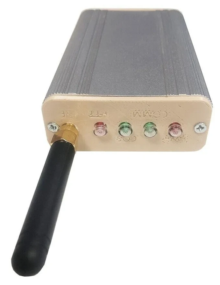
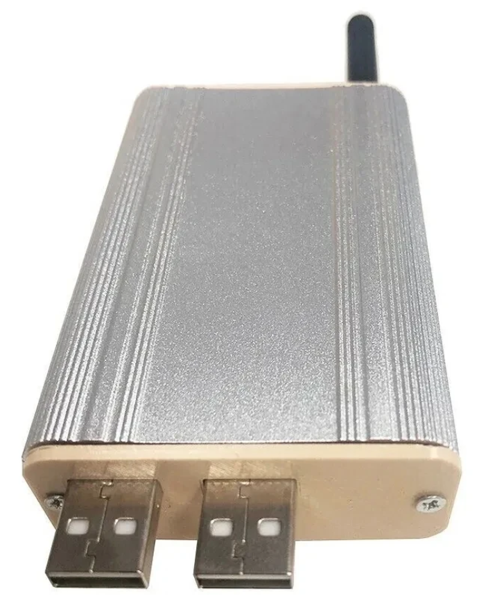
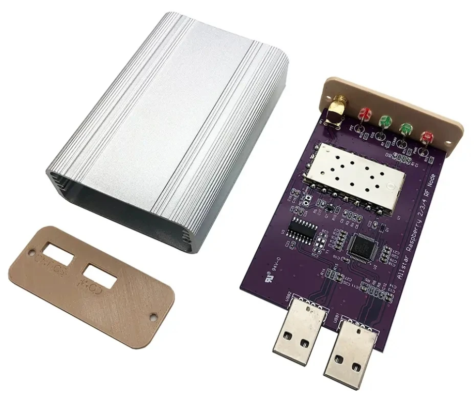
Jumbospot SHARI SA818 Amateur Radio AllStarLink Radio Interface Front Panel ViewJumbospot SHARI SA818 Amateur Radio AllStarLink Radio Interface Rear ViewJumbospot SHARI SA818 Amateur Radio AllStarLink Radio Interface stripped down View
The two USB connectors on the SHARI device are position such that they plug into two of the available 4 USB ports on the RaspberryPi without the need for cables. This keeps the whole solution together in one neat package.
Before you start you will need to obtain a node number and secret (password) from the AllStarLink Portal. To get this you will need to provide proof to the AllStarLink administrators that you are a licensed Amateur Radio (HAM) operator. This is done by uploading a copy of the first page of your HAM licence to the website for the admin team to check. This can take 24hrs to be completed so make sure you get this all done before trying to build your node. You cannot build a node successfully without a node number and secret.
Of course you will also need a transceiver that can operate on the 438.800Mhz frequency or other frequency of your choice on the 2m or 70cm HAM band.
You will also need to open port 4569 on your internet router and setup port forwarding to the IP Address that you will be using on your RaspberryPi node. It’s important to use a static IP Address on your RaspberryPi.
There are quite a few different Linux based operating system (O/S) images that are available for the RaspberryPi devices that have been specifically tailored for the AllStarLink node and include all the necessary software and library packages out the box.
Once downloaded you need to burn the ISO image onto a suitable SD card for your RaspberryPi. I use BalenaEtcher as it’s extremely quick and reliable at burning ISO images to SD cards.
Of course if you are a hardline Linux command line junkie you can always use dd to create the SD card.
Once you’ve got your O/S onto your SD card, slot it into your RaspberryPi making sure your SHARI device is connected to the two USB ports and then power it up. Make sure you have a good PSU for the RaspberryPi as the two devices together draw around 3A of current during the transmit cycle. (I use a 3.6A PSU from Amazon).
The default login for the Raspbian O/S is shown below. Login via SSH and configure your RaspberryPi for your local network. It’s important to use a static IP Address configured either directly on the RaspberryPi or via DHCP in your router.
Next you need to change directory into the asterisk config file directory using the command shown below:
cd /etc/asterisk
In this directory you will find all the default config files that come as part of the distro. For this build we’re not going to use them and so we need to move them out of the way ready for a set of config files that have already been configured correctly.
Using the following commands create a new directory, move into that new directory and then move all the unwanted configuration files into it:
mkdir ORIGINAL-CONF-FILES
cd ./ORIGINAL-CONF-FILES
mv ../*.conf ./
ls -la
cd ../
You should now be back in the /etc/asterisk directory which will now be empty apart from the custom directory which we left in place.
You now need to copy the correctly configured configuration files into the /etc/asterisk directory. Start by downloading the zip file containing the new configuration files
Download removed as deprecated.
Once downloaded, copy the .zip file into the repeater users home directory (/home/repeater) using either scp on the Linux command line or if using Windows you can use the FileZilla Client in SFTP mode using the login details above.
Once you have the .zip file in the repeater user’s home directory you need to copy the file into the /etc/asterisk directory as user root:
Next as user root, change directory into the /etc/asterisk directory and unzip the .zip file:
cd /etc/asterisk
unzip ./AllStarLink-Config-v3.zip
Once the file is unzipped you will have a directory called AllStarLink-Config in the /etc/asterisk directory. You now need to cd into the directory, copy all the files out of it into the /etc/asterisk directory leaving a copy in the AllStarLink-Config directory for future reference:
cd /etc/asterisk/AllStarLink-Config
cp ./* /etc/asterisk
cd /etc/asterisk
You now need to move a couple of files into the repeater users home directory using the following commands:
The gpioBASH script and configuration details were supplied by Mark, G1INU in the Digital Voice room on the Matrix. It adds the COS light functionality to the setup. The COS light will now light every time the SA818 hears RF on the input.
The next thing you need to do is configure the SA818 radio device in the SHARI. The script I used was originally from https://wiki.fm-funknetz.de/doku.php?id=fm-funknetz:technik:shari-sa818 all I’ve done is change the entries to switch off CTCSS and change the frequency to 438.800Mhz. Configuring the SA818 is done by running the SA818-running.pyPython programme that you moved into the repeater user home directory. Making sure you are still user root, run the following commands:
cd /home/repeater
./SA818-running.py
At this point your SHARI SA818 device will be configured to operate on 438.800Mhz and CTCSS will be disabled.
If you want to change the frequency or enable and set a CTCSS tone to access the node you will need to edit the Python programme using your favourite text editor and change the entries accordingly. Once changed rerun the program as shown above and your SHARI will be reconfigured to your new settings.
Next you need to move the allmon.ini.php file into the correct directory so that it enables access to the Allstar Monitor web page on the device so that you can manage connecting/disconnecting nodes. Use the following commands as user root to achieve this:
The allmon.ini.php file needs to have your node name entered into it to work correctly. As user root, change directory and edit the file using your favourite editor.
cd /var/www/html/allmon2
Using your text editor, search for the line starting [XXXXX] and change the XXXXX to your node number. Save the change and exit the file.
At this point you are almost complete, all that is left to do is add your node number and node secret into the appropriate configuration files in the /etc/asterisk directory.
Since I am a Linux command line junkie I use vi to edit all the configuration files on the command line as user root, but you can use any editor of your choice.
cd /etc/asterisk
Start with the extensions.conf file. Search for the line starting with NODE = and delete the XXXXX entry and insert your node number. Save the file and exit it.
Next you need to edit the iax.conf file. This time search for the line starting with register= and change the XXXXX for your node number and the YYYYYYYYYYYY for your node secret. Be careful not to accidentally delete any other characters in the lines otherwise it will corrupt the configuration file.
In the same file search for the two lines that start with secret = and change the YYYYYYYYYYYY for your node secret. Once you have changed both of the secret entries, save and exit the file.
The final file to edit is the rpt.conf file. Once again open the file using your favourite editor and search for the line starting with XXXXX = radio@127.0.0.1:4569/XXXXX, change the XXXXX entries for your node number making sure not to delete any other characters next to the XXXXX entries.
Further down in the same file there is a line that starts with [XXXXX], once again change the XXXXX for your node number making sure to keep the square brackets at each end of the node number as you edit it.
Finally move down to the very bottom of the file and find the two lines that start with /home/repeater/gpio, once again change the XXXXX entries for your node number.
The final thing to change in the rpt.conf file is to replace my callsign with your own callsign so that the node identifies itself correctly. Scroll through the file until you find the two lines shown below, delete M0AWS and add your own callsign instead making sure you keep all the spaces between words as shown below.
idrecording = |i DE M0AWS
idtalkover = |i DE M0AWS
Once this is done, save and exit the file. At this point your node should be fully configured and will only require a reboot to get it working.
As user root, reboot your raspi using the reboot command.
reboot
Once your raspi comes back online, login using SSH as user repeater and then become root user using the sudo command detailed above.
You now need to create the admin user password for the Allstar Monitor web page on the device. This is done using the following commands as user root:
cd /var/www/html/allmon2
htpasswd -c .htpasswd admin
You will be asked to enter a password twice for the admin user. Make sure you make a note of this user/password as you will need it to login to the web page.
Finally check that the controlpanel.ini.php file is in the /var/www/html/allmon2 directory:
ls -la /var/www/html/allmon2/controlpanel.ini.php
If the file isn’t shown in the directory, enter the following commands to create the file in the correct place as user root and then exit the SSH session:
cd /var/www/html/allmon2
cp ./controlpanel.ini.txt ./controlpanel.ini.php
cd
exit
Once this is done your configuration is complete, logout from the terminal session by entering exit once more and your SSH session will terminate.
Using your favourite web browser enter the IP Address of your raspi into the URL bar as shown below:
http://<Your-Raspi-IP>/allmon2
Note: remove the <> from the URL once you have entered the required information.
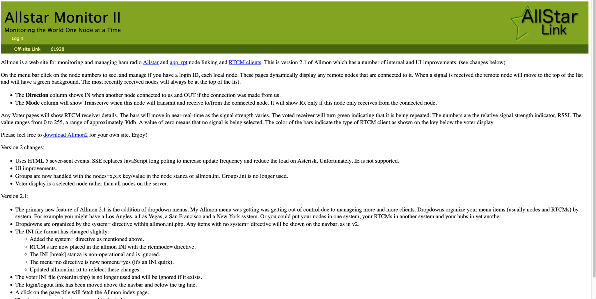
Once this is done you should be presented with your node control panel as shown below.
First visit to the AllStar Monitor Web Page
Login using Admin and the password you set above and you are now ready to start using your node.
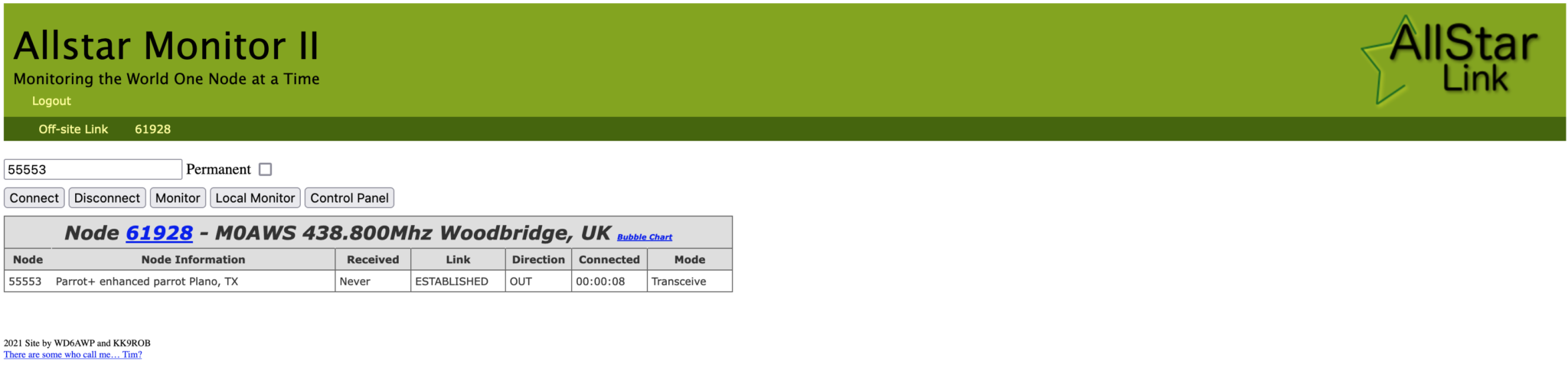
It’s a good idea to connect to node 55553 which is a parrot test node to check your audio levels. You can do this by entering the node into the field at the top left and pressing the connect button.
M0AWS AllStarLink Node 61928 connected to 55553 Parrot
Once connected, tune your radio to 438.800Mhz FM and transmit a test message using your callsign and test123, or something similar. The parrot will then play your recording back to you so that you can hear how you sound. It will also comment on your audio level as to whether it is OK or not.
You are now connected to AllStarLink network and have the world at your finger tips. Below is a small list of nodes in the UK, Australia and America to get you started chatting with other HAMs via your node.
57881	Matrix HAM Radio Space AllStarLink Node (Hosted by Dk1MI)
55553	ASL Parrot for testing
41522	M0HOY HUBNet Manchester, UK
60349	VK6CIA 439.275 Perth, Western Australia
51077	VK6SEG South West Hub B Albany WA
2167	M0JKT FreeSTAR UK HUB 2 freestar.network
53573	NWAG NW AllStar Group Lancashire, UK
27339	East Coast Hub Wilmington NC USA
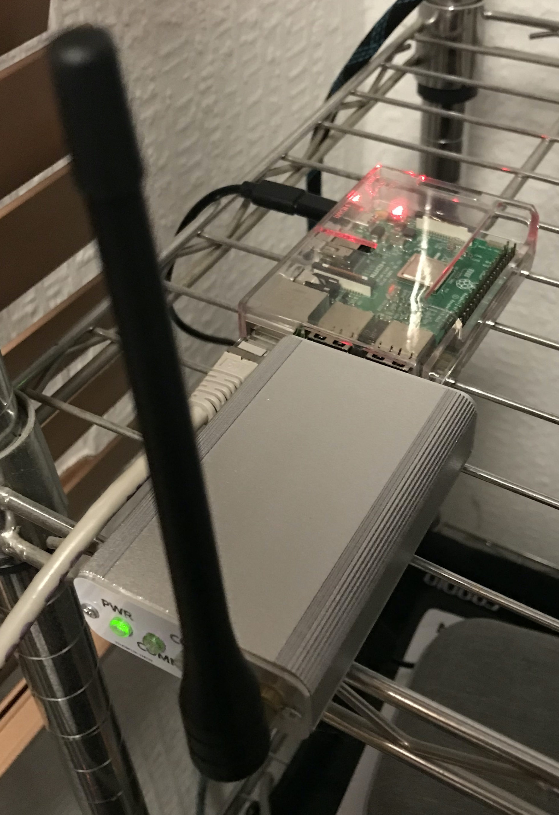
M0AWS AllStarLink Node 61928 sitting on the equipment rack
Thanks to Michael, DK1MI for building and hosting the Matrix HAM Radio Space AllStarLink Node (57881) and getting us all started in the world of AllStarLink!
We hope to be having regular Matrix Net’s on the node soon for all Matrix members and visitors. We’ll organise days/times via the Digital Voice room.
More soon …
We use cookies to ensure that we give you the best experience on our website. If you continue to use this site we will assume that you are happy with it.