I’ve recently built another AllStarLink node to compliment my personal 70cm band SHARI node as I thought since I have a full duplex dual band handheld it would be great to have another node that I could connect to FreeStar or HUBNet at the same time as monitoring the Matrix node.
Rather than build another personal node I decided this time I would build a public node, obtain a callsign from the RSGB and make it available to the HAM’s locally on the 2m band.
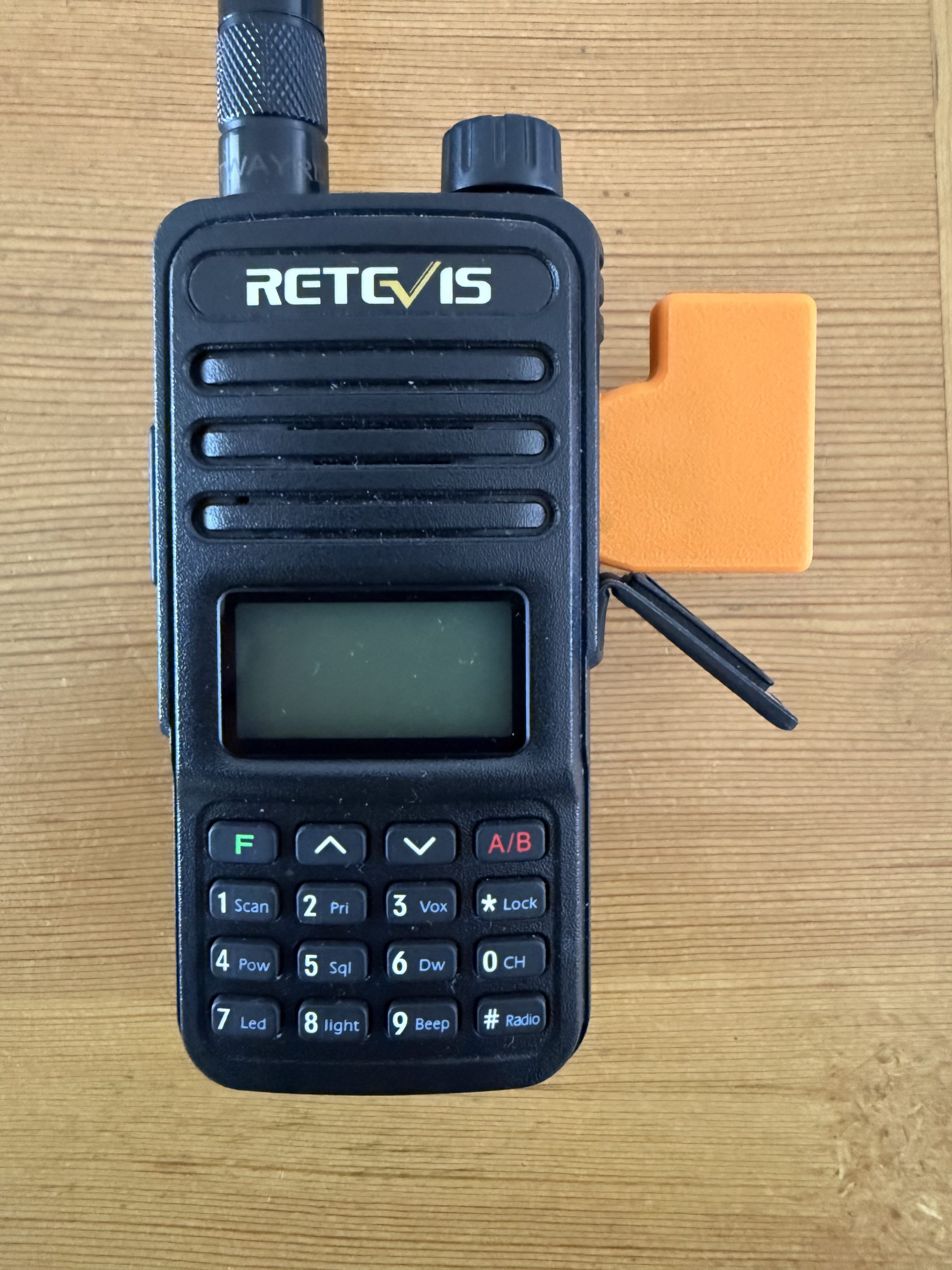
Initially I thought I may be able to use my old Retevis RT85 handheld and AIOC board for the 2m node but, after a little testing it soon became apparent that it overheats during long overs (which are common on AllStarLink) and so, I needed to find another solution.
AIOC connected to the Retevis RT85.
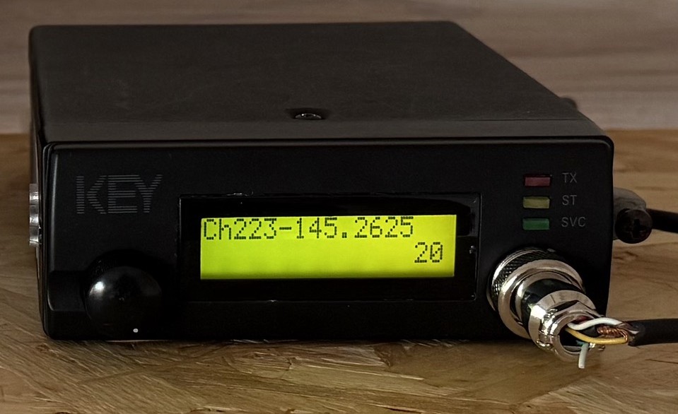
Chatting about this in the main Matrix HAM Radio roomSteve, M0XVT sent me a message saying he had an old Key KM-4000 converted PMR radio that had been reprogrammed for the 2m band that he was looking to sell and that it might be ideal for the new node. Wasting no time, we came to an agreement and I was soon the proud owner of a converted PMR transceiver.
Key KM4000 2m Band PMR Radio
The KM4000 transceiver has a standard output of 15w, 10w more than I needed for the gateway and so I had to reduce the output. A quick search on the internet and I found the Thames Valley Repeater Group website that had all the information required to turn down the output.
I also had to reprogramme channel 1 to the frequency and CTCSS tone allocated to me by the RSGB so that in the event of a power outage when the radio came back on it automatically jumps to channel 1 which would be correctly setup for operation.
Unfortunately the software for programming the radio is only available for windows and so I had to build a virtual machine running windows 10 to be able to reprogramme the radio.
Once this was done I rewired the AIOC USB audio device to work with the KM4000 radio and built the AllStarLink node on a spare RaspberryPi 4.
For an antenna I made a simple end fed vertical dipole from some RG58 coax and mounted it 8m up on one of my Spiderpoles in the garden. Running a coax feed out to the antenna I did some tests into the Parrot to get the audio levels setup and checked that the DTMF codes were interpreted correctly and that the node switched connections without error.
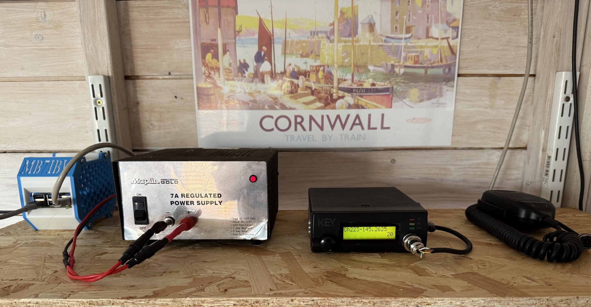
MB7IBW Internet Gateway hardware at the M0AWS QTH
Once this was done I had a few test conversations with stations on the Matrix node and FreeStar to ensure all was fine and then set the gateway status to “Operational” on the RSGB website.
This worked fine for a while with myself and some local stations using the node regularly but, then the hot weather arrived and things started to overheat. The transceiver was getting incredibly hot in the 30c+ summer temperatures and the power supply was also running extremely hot and so I decided to add some cooling.
Cooling the PSU was simple, it has a perforated top panel to which I strapped a cooling fan. This worked great and brought the temperature of the PSU down considerably.
The radio wasn’t so easy to cool. It has a solid case cover top and bottom and so cooling wasn’t going to be a simple affair.
I decided to remove the covers and drill some holes into them to allow airflow through the unit and strapped a fan to the top cover to pull the hot air out. This worked well however, on both transmit and receive I now had a warbling sound on the audio that was caused by the motor of the fan when powered up.
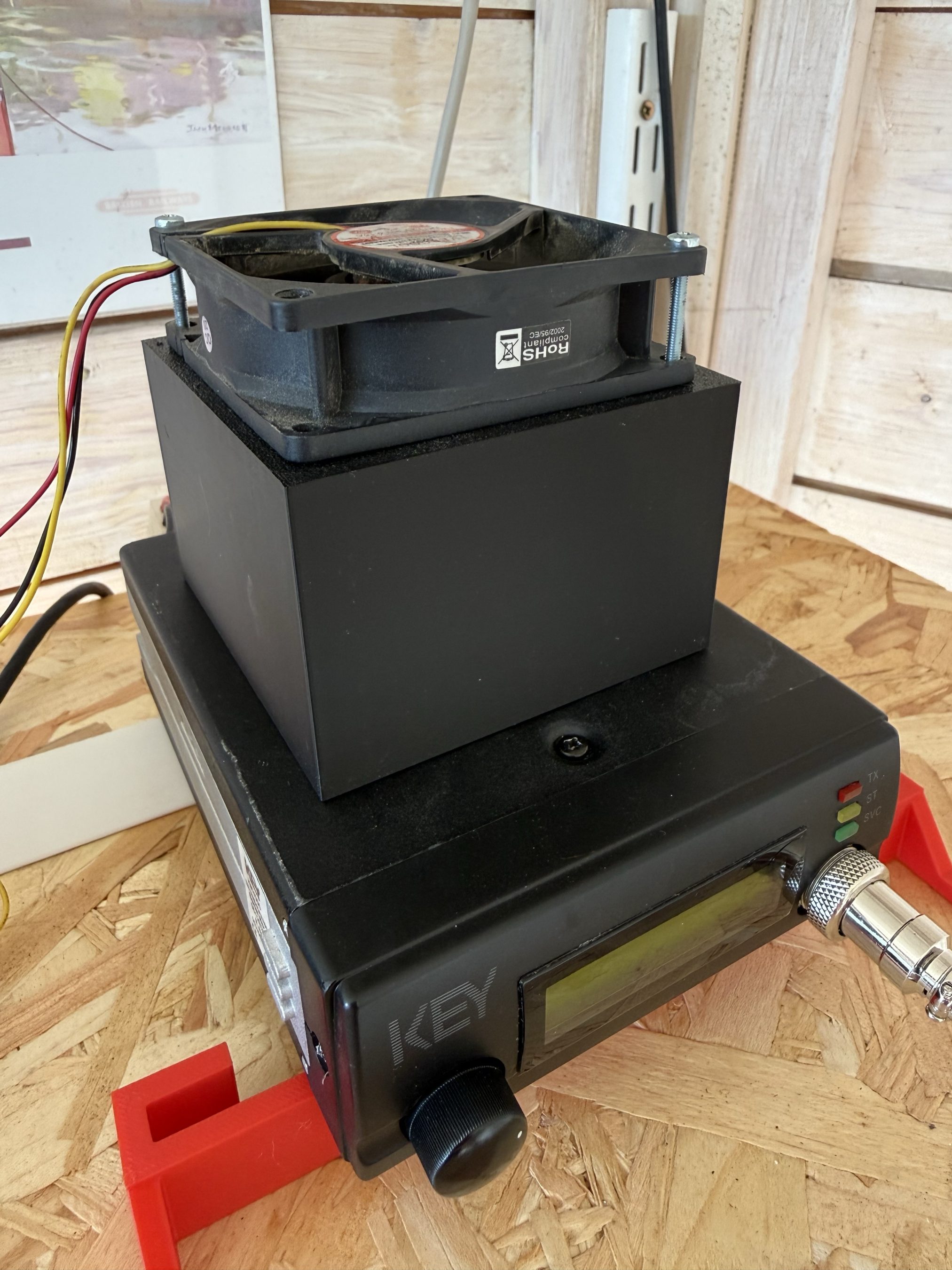
I found that lifting the fan up away from the case of the radio the warbling audio disappeared and things were back to normal and so, I decided to design a cooling tube to fit to the top of the radio to allow full airflow from the fan but, with the fan raised up away from the radio to resolve the audio problem.
Jumping into my CAD software I quickly designed a cooling tower to fit on the top of the radio that would allow the fan to sit far enough away from the radio so as to not affect the audio whilst at the same time pulling the hot air out of the radio and drawing cooler air in through the bottom of the case.
The cooler worked great with the radio staying cool to the touch and no longer overheating and reducing O/P power.
It’s amazing how much dust and dirt is in the air from all the farming activities going on at the end of our garden and how much of it is sucked in by the cooling fan. Regular cleaning is a must!
The MB7IBW Internet Gateway has been on air since mid June 2026 and has worked well. It spends most of its time connected to either FreeStar or HUBNet with connections to the Matrix Node when we have our nets.
Details on Frequency, CTCSS etc can be found under the MB7IBW menu above.
Sadly the initial interest from local HAMs has now wained and I am mostly the only user of the gateway. I was hoping more people would use it and bring some life to the 2m band, I guess time will tell.
It’s been a fun project and was interesting to go through the callsign allocation process with the RSGB representative. It was much easier than I thought it would be.
I now have all the parts to build another Internet Gateway for the 4m band. Hopefully that may attract some more interest. It’s certainly worth a try!
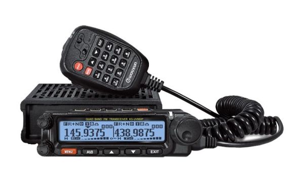
I recently decided to look into a 2m/70cm FM radio for the shack for use on the local 2m/70cm repeaters and was considering the offerings from Yaesu and Icom however, the Wouxun KG UV-980PL caught my eye as it is a quad band, full duplex radio. Not knowing much about Wouxun radios I had to do some research to get an idea of what it’s like. Generally the radio gets very good reviews and most mention the excellent build quality.
There are two versions of the 980P radio, the 980PL that offers 6/4/2m and 70cm bands and the 980P that offers 10/6/2m and 70cm. The 4m is a band I’ve been wanting to try for some time and the 980PL with it’s 4m band coverage became even more appealing.
Wouxun KG UV-980PL Quad Band FM Duplex Transceiver
I decided to take a trip down to Martin Lynch and Sons (MLANDS), a good 2 hours or more drive for me, so that I could get hands on with the radios that I had been looking at.
I invited Alan, G1SQB along for the ride and a day out playing with radios as he lives 3 miles away and we often chat on air.
Arriving at the store we grabbed a hot brew and set about playing with the great selection of radios on display.
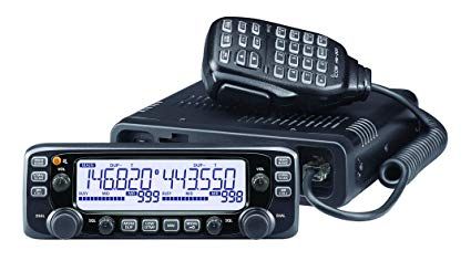
I initially looked at the Icom IC-2730E, a dual band full duplex transceiver that has been around for about 10 years and has good reviews. As expected the build quality is excellent and very easy to use. I found I was soon able to set up memories etc via the front panel controls. The only draw back is that it isn’t supported by the CHIRP programming software that I use. Other than that it certainly meets all the requirements for a 2m/70cm FM transceiver
Icom IC-2730E FM Duplex Transceiver
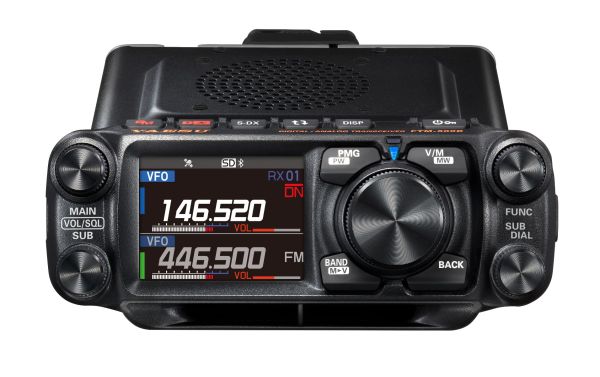
Next I moved on to the offerings from Yaesu including the FTM-500DE 2m/70cm transceiver. The colour screen is very nice and the menu system very easy to use however, the price is getting on for close to double that of the other radios and it doesn’t really offer anything more that interests me since I’m only looking for an analog radio.
Yaesu FTM-500DR dual band FM Transceiver
Sadly there wasn’t a Wouxun UV-980PL out on display and so I had to persuade the salesman to get one out of stock for me to play with. Unpacking the radio I was surprised at how good the build quality is, it really is comparable to the other radios that I had been looking at.
The Wouxun menu system is fairly easy to use once you’ve looked at the manual and got to grips the abbreviations used. The big plus is that this radio is CHIRP compatible with an optional programming cable (£19) and so loading the memories with repeaters etc will be extremely easy.
The Wouxun has dual receivers built in with a quad-plexer so, you can transmit on one band whilst listening to another band on the other receiver. One thing to note is that the 1st receiver covers all the bands, 6/4/2m and 70cm however, the 2nd receiver only covers 2m and 70cm so, it’s not possible to receive 4m and 6m at the same time. The radio also only has one antenna connection on the rear, would had been great if it had one connector for each receiver.
The really good thing about the Wouxun UV-980PL is that it comes with everything you will need, apart from the programming cable!
After much tinkering I decided to purchase the Wouxun KG UV-980PL, a Diamond V2000 6/2m and 70cm antenna plus 20m of Hyperflex-13 coax cable and connectors.
In the box you’ll find two mounting options for the removable head. There is a short connecting cable for use when the head is mounted directly on the radio body and a 5m long connecting cable for mounting the head remotely. This is really useful as I wanted to mount the head on a mic boom arm so that it’s easily accessible and didn’t clutter the desk space in the shack.
Wouxun KG UV-980PL head mounted on a Mic boom arm
Since the radio also comes with the mobile mount I’ve fixed the radio body on the wall behind the PC monitor out the way. This setup has proven to be extremely good as I can see what’s happening on the display at a glance and easily grab the mic if called.
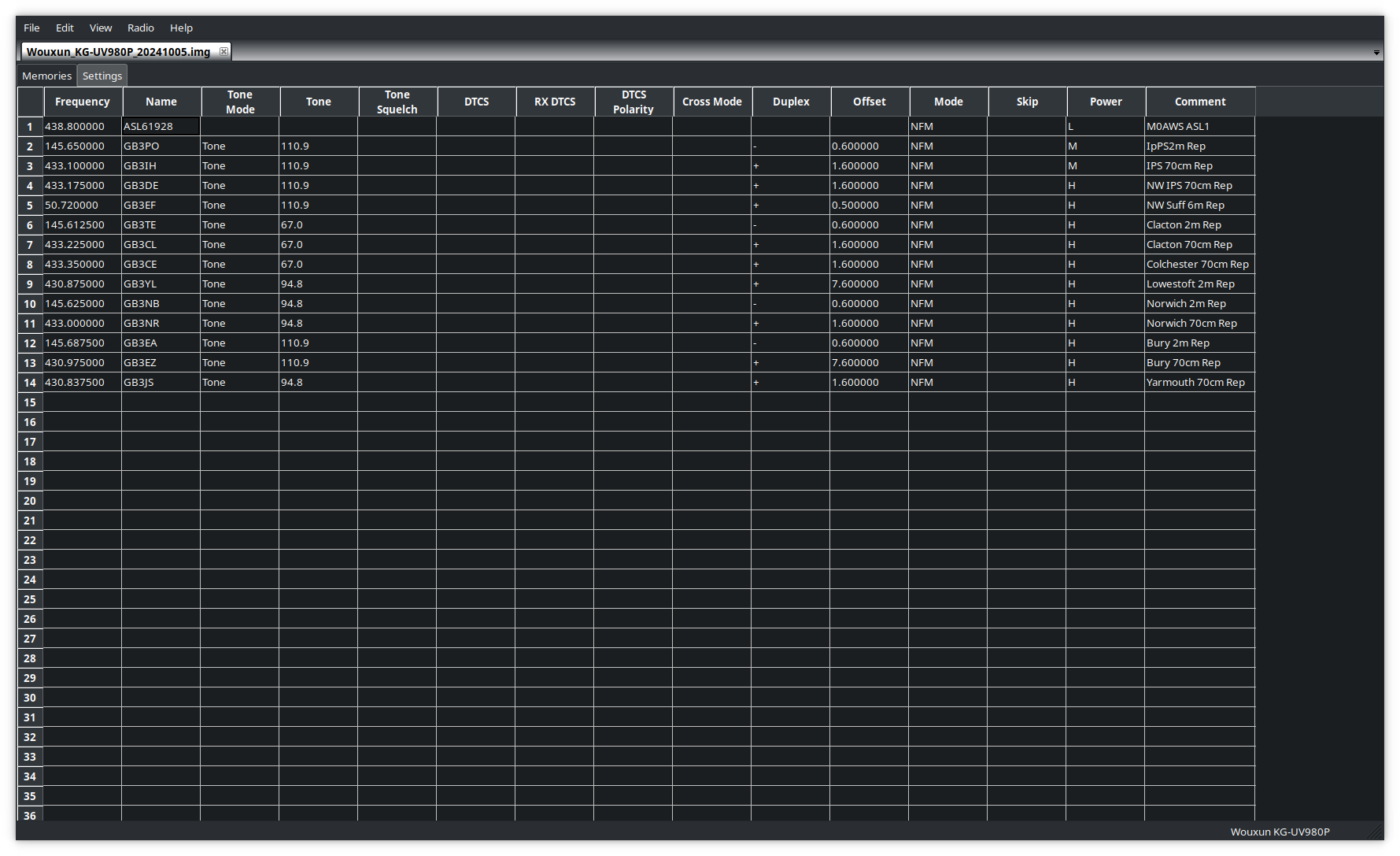
Programming the radio memories is extremely quick and easy using CHIRP. I had the local repeaters and my AllStarLink node frequencies and offsets uploaded to the radio in no time at all and was soon on air.
Programming the memories on the Wouxun UV-980PL using CHIRP
The microphone that comes with the radio is extremely good. You can operate most of the controls on the radio directly from the mic with ease and it has a good feel in the hand. Audio reports have also been very good and there’s no need to change it.
I’ve not yet got the new Diamond V2000 antenna erected but, I’ve been using the radio with my homebrew 2m/70cm end fed vertical dipole and my 4m band end fed vertical dipole and am getting excellent results. I can access all the local repeaters using the lowest power output setting and only have to use the medium/high setting for the repeaters that are further afield.
On the 4m band the radio performs well and I’ve been surprised at the distances I’ve been able to cover even though my 4m antenna is only 6-7m above the ground currently.
A few days after I got the new Wouxun radio there was an ARISS event whereby a group of Girl Guides would be talking to Astronaut Sunita Williams aboard the ISS. This was a great opportunity to test the receive capability of the radio and so I setup ready for the pass. Using just my simple 2m/70cm end fed vertical dipole I got great reception as can be heard in the video below.
Overall I’m extremely pleased with the Wouxun KG UV-980PL quad band radio and considering it’s much cheaper than the offerings from the main radio manufacturers it’s well built and performs extremely well. If you’re looking for a simple, analog FM radio for 6/4/2m/70cms then you can’t beat it!
Please note: This build is now deprecated and will no longer work. Please use the new AllStarLink 3 build process as documented on the AllStarLink website.
We’ve recently added a new room to the Matrix HAM Radio Space for Digital Voice modes as this was an area of interest that didn’t really fit into any of the other rooms.
The new Digital Voice room has attracted a lot of attention from members, with a lot of the focus being on the AllStarLink system. Michael, DK1MI built an AllStarLink node in the cloud for us all to use for Matrix Nets and so I decided I had to get in on the fun.
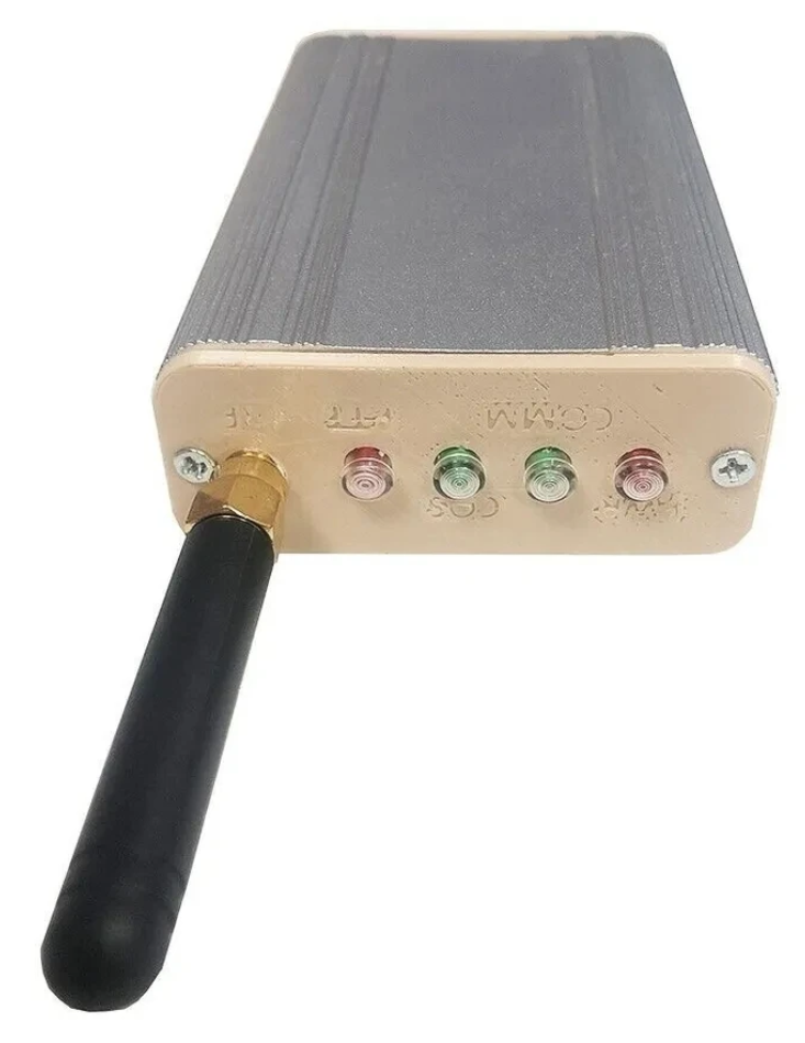
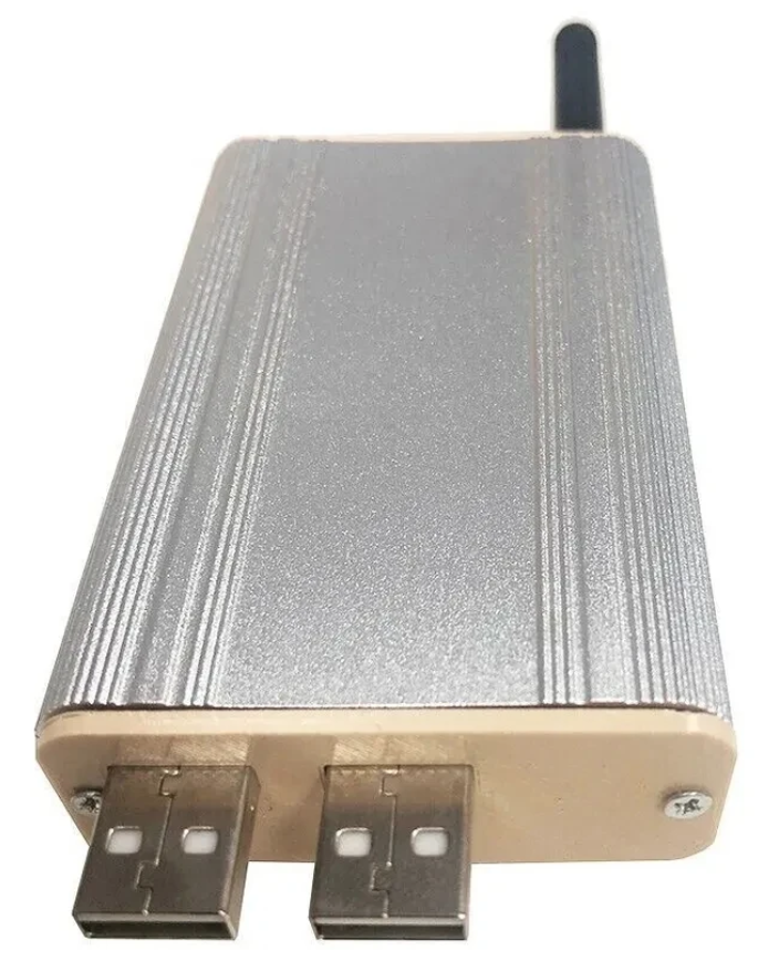
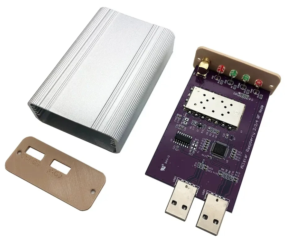
Jumbospot SHARI SA818 Amateur Radio AllStarLink Radio Interface Front Panel ViewJumbospot SHARI SA818 Amateur Radio AllStarLink Radio Interface Rear ViewJumbospot SHARI SA818 Amateur Radio AllStarLink Radio Interface stripped down View
The two USB connectors on the SHARI device are position such that they plug into two of the available 4 USB ports on the RaspberryPi without the need for cables. This keeps the whole solution together in one neat package.
Before you start you will need to obtain a node number and secret (password) from the AllStarLink Portal. To get this you will need to provide proof to the AllStarLink administrators that you are a licensed Amateur Radio (HAM) operator. This is done by uploading a copy of the first page of your HAM licence to the website for the admin team to check. This can take 24hrs to be completed so make sure you get this all done before trying to build your node. You cannot build a node successfully without a node number and secret.
Of course you will also need a transceiver that can operate on the 438.800Mhz frequency or other frequency of your choice on the 2m or 70cm HAM band.
You will also need to open port 4569 on your internet router and setup port forwarding to the IP Address that you will be using on your RaspberryPi node. It’s important to use a static IP Address on your RaspberryPi.
There are quite a few different Linux based operating system (O/S) images that are available for the RaspberryPi devices that have been specifically tailored for the AllStarLink node and include all the necessary software and library packages out the box.
Once downloaded you need to burn the ISO image onto a suitable SD card for your RaspberryPi. I use BalenaEtcher as it’s extremely quick and reliable at burning ISO images to SD cards.
Of course if you are a hardline Linux command line junkie you can always use dd to create the SD card.
Once you’ve got your O/S onto your SD card, slot it into your RaspberryPi making sure your SHARI device is connected to the two USB ports and then power it up. Make sure you have a good PSU for the RaspberryPi as the two devices together draw around 3A of current during the transmit cycle. (I use a 3.6A PSU from Amazon).
The default login for the Raspbian O/S is shown below. Login via SSH and configure your RaspberryPi for your local network. It’s important to use a static IP Address configured either directly on the RaspberryPi or via DHCP in your router.
Next you need to change directory into the asterisk config file directory using the command shown below:
cd /etc/asterisk
In this directory you will find all the default config files that come as part of the distro. For this build we’re not going to use them and so we need to move them out of the way ready for a set of config files that have already been configured correctly.
Using the following commands create a new directory, move into that new directory and then move all the unwanted configuration files into it:
mkdir ORIGINAL-CONF-FILES
cd ./ORIGINAL-CONF-FILES
mv ../*.conf ./
ls -la
cd ../
You should now be back in the /etc/asterisk directory which will now be empty apart from the custom directory which we left in place.
You now need to copy the correctly configured configuration files into the /etc/asterisk directory. Start by downloading the zip file containing the new configuration files
Download removed as deprecated.
Once downloaded, copy the .zip file into the repeater users home directory (/home/repeater) using either scp on the Linux command line or if using Windows you can use the FileZilla Client in SFTP mode using the login details above.
Once you have the .zip file in the repeater user’s home directory you need to copy the file into the /etc/asterisk directory as user root:
Next as user root, change directory into the /etc/asterisk directory and unzip the .zip file:
cd /etc/asterisk
unzip ./AllStarLink-Config-v3.zip
Once the file is unzipped you will have a directory called AllStarLink-Config in the /etc/asterisk directory. You now need to cd into the directory, copy all the files out of it into the /etc/asterisk directory leaving a copy in the AllStarLink-Config directory for future reference:
cd /etc/asterisk/AllStarLink-Config
cp ./* /etc/asterisk
cd /etc/asterisk
You now need to move a couple of files into the repeater users home directory using the following commands:
The gpioBASH script and configuration details were supplied by Mark, G1INU in the Digital Voice room on the Matrix. It adds the COS light functionality to the setup. The COS light will now light every time the SA818 hears RF on the input.
The next thing you need to do is configure the SA818 radio device in the SHARI. The script I used was originally from https://wiki.fm-funknetz.de/doku.php?id=fm-funknetz:technik:shari-sa818 all I’ve done is change the entries to switch off CTCSS and change the frequency to 438.800Mhz. Configuring the SA818 is done by running the SA818-running.pyPython programme that you moved into the repeater user home directory. Making sure you are still user root, run the following commands:
cd /home/repeater
./SA818-running.py
At this point your SHARI SA818 device will be configured to operate on 438.800Mhz and CTCSS will be disabled.
If you want to change the frequency or enable and set a CTCSS tone to access the node you will need to edit the Python programme using your favourite text editor and change the entries accordingly. Once changed rerun the program as shown above and your SHARI will be reconfigured to your new settings.
Next you need to move the allmon.ini.php file into the correct directory so that it enables access to the Allstar Monitor web page on the device so that you can manage connecting/disconnecting nodes. Use the following commands as user root to achieve this:
The allmon.ini.php file needs to have your node name entered into it to work correctly. As user root, change directory and edit the file using your favourite editor.
cd /var/www/html/allmon2
Using your text editor, search for the line starting [XXXXX] and change the XXXXX to your node number. Save the change and exit the file.
At this point you are almost complete, all that is left to do is add your node number and node secret into the appropriate configuration files in the /etc/asterisk directory.
Since I am a Linux command line junkie I use vi to edit all the configuration files on the command line as user root, but you can use any editor of your choice.
cd /etc/asterisk
Start with the extensions.conf file. Search for the line starting with NODE = and delete the XXXXX entry and insert your node number. Save the file and exit it.
Next you need to edit the iax.conf file. This time search for the line starting with register= and change the XXXXX for your node number and the YYYYYYYYYYYY for your node secret. Be careful not to accidentally delete any other characters in the lines otherwise it will corrupt the configuration file.
In the same file search for the two lines that start with secret = and change the YYYYYYYYYYYY for your node secret. Once you have changed both of the secret entries, save and exit the file.
The final file to edit is the rpt.conf file. Once again open the file using your favourite editor and search for the line starting with XXXXX = radio@127.0.0.1:4569/XXXXX, change the XXXXX entries for your node number making sure not to delete any other characters next to the XXXXX entries.
Further down in the same file there is a line that starts with [XXXXX], once again change the XXXXX for your node number making sure to keep the square brackets at each end of the node number as you edit it.
Finally move down to the very bottom of the file and find the two lines that start with /home/repeater/gpio, once again change the XXXXX entries for your node number.
The final thing to change in the rpt.conf file is to replace my callsign with your own callsign so that the node identifies itself correctly. Scroll through the file until you find the two lines shown below, delete M0AWS and add your own callsign instead making sure you keep all the spaces between words as shown below.
idrecording = |i DE M0AWS
idtalkover = |i DE M0AWS
Once this is done, save and exit the file. At this point your node should be fully configured and will only require a reboot to get it working.
As user root, reboot your raspi using the reboot command.
reboot
Once your raspi comes back online, login using SSH as user repeater and then become root user using the sudo command detailed above.
You now need to create the admin user password for the Allstar Monitor web page on the device. This is done using the following commands as user root:
cd /var/www/html/allmon2
htpasswd -c .htpasswd admin
You will be asked to enter a password twice for the admin user. Make sure you make a note of this user/password as you will need it to login to the web page.
Finally check that the controlpanel.ini.php file is in the /var/www/html/allmon2 directory:
ls -la /var/www/html/allmon2/controlpanel.ini.php
If the file isn’t shown in the directory, enter the following commands to create the file in the correct place as user root and then exit the SSH session:
cd /var/www/html/allmon2
cp ./controlpanel.ini.txt ./controlpanel.ini.php
cd
exit
Once this is done your configuration is complete, logout from the terminal session by entering exit once more and your SSH session will terminate.
Using your favourite web browser enter the IP Address of your raspi into the URL bar as shown below:
http://<Your-Raspi-IP>/allmon2
Note: remove the <> from the URL once you have entered the required information.
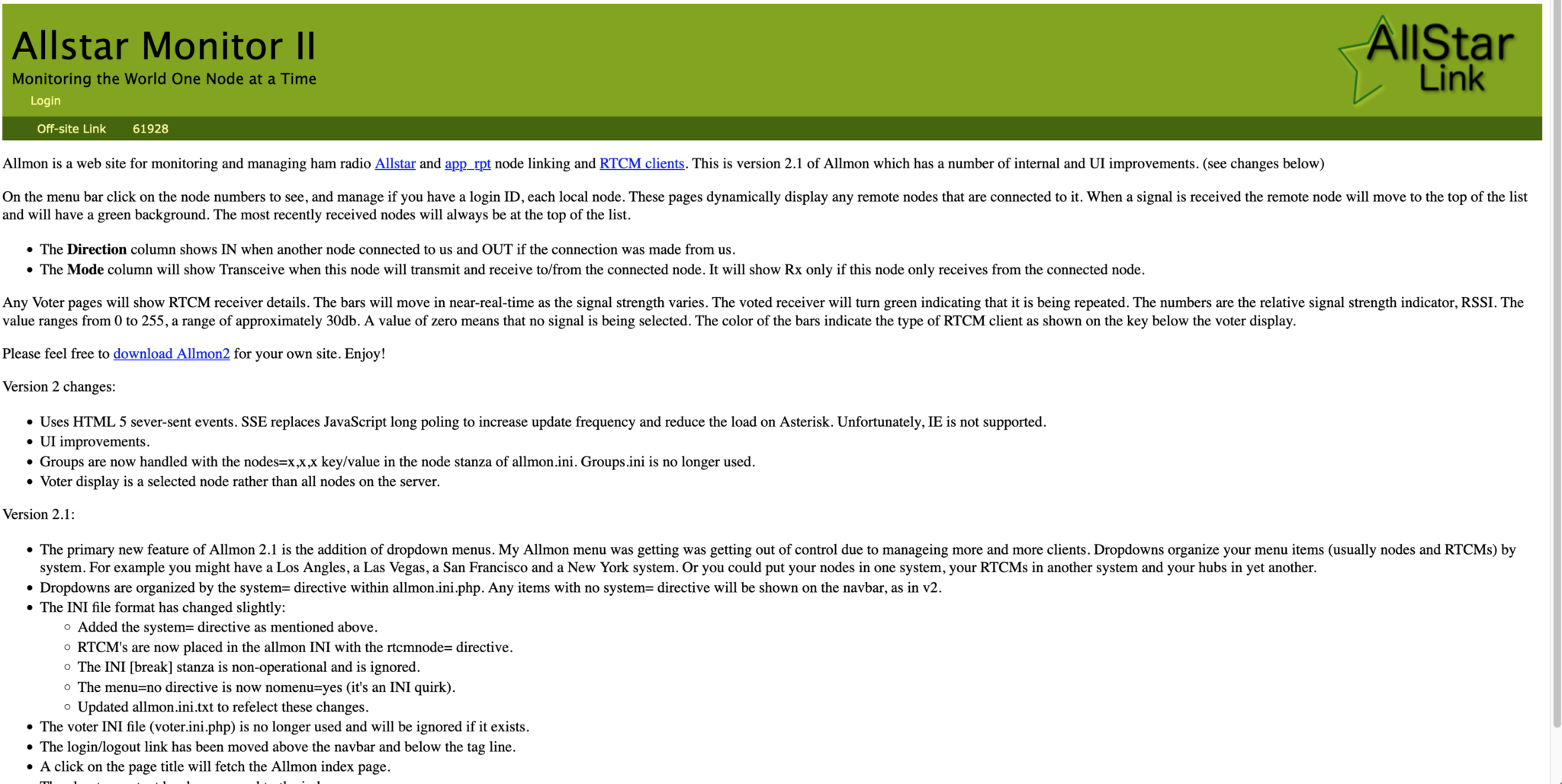
Once this is done you should be presented with your node control panel as shown below.
First visit to the AllStar Monitor Web Page
Login using Admin and the password you set above and you are now ready to start using your node.
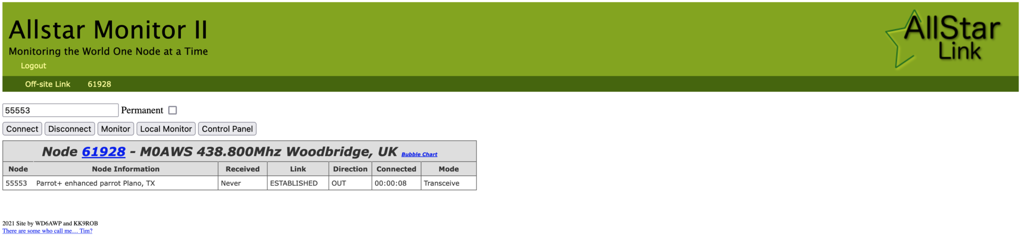
It’s a good idea to connect to node 55553 which is a parrot test node to check your audio levels. You can do this by entering the node into the field at the top left and pressing the connect button.
M0AWS AllStarLink Node 61928 connected to 55553 Parrot
Once connected, tune your radio to 438.800Mhz FM and transmit a test message using your callsign and test123, or something similar. The parrot will then play your recording back to you so that you can hear how you sound. It will also comment on your audio level as to whether it is OK or not.
You are now connected to AllStarLink network and have the world at your finger tips. Below is a small list of nodes in the UK, Australia and America to get you started chatting with other HAMs via your node.
57881	Matrix HAM Radio Space AllStarLink Node (Hosted by Dk1MI)
55553	ASL Parrot for testing
41522	M0HOY HUBNet Manchester, UK
60349	VK6CIA 439.275 Perth, Western Australia
51077	VK6SEG South West Hub B Albany WA
2167	M0JKT FreeSTAR UK HUB 2 freestar.network
53573	NWAG NW AllStar Group Lancashire, UK
27339	East Coast Hub Wilmington NC USA
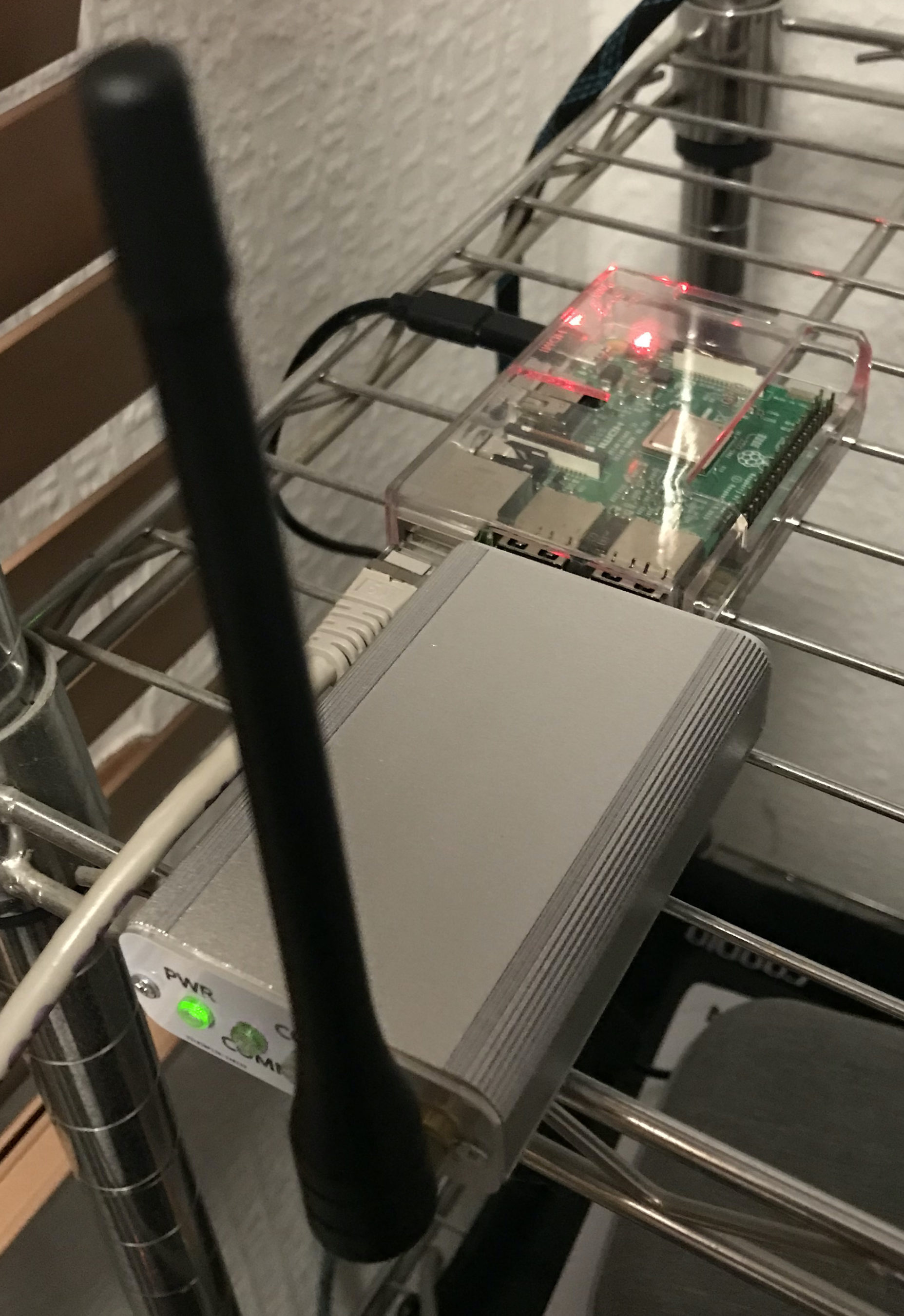
M0AWS AllStarLink Node 61928 sitting on the equipment rack
Thanks to Michael, DK1MI for building and hosting the Matrix HAM Radio Space AllStarLink Node (57881) and getting us all started in the world of AllStarLink!
We hope to be having regular Matrix Net’s on the node soon for all Matrix members and visitors. We’ll organise days/times via the Digital Voice room.
More soon …
We use cookies to ensure that we give you the best experience on our website. If you continue to use this site we will assume that you are happy with it.