It’s been a busy week of software bug fixes and enhancements on piHPSDR-Improved and piSync.
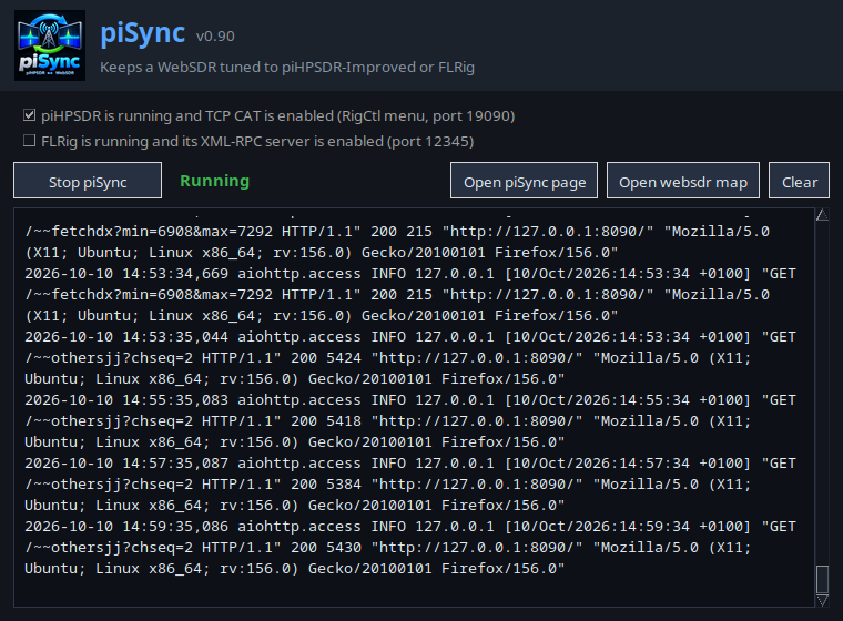
piSync v0.9 is currently in test after we added the support for FLRig. This extends the support for many transceivers new and old along side piHPSDR-Improved and makes it useful to HAMs who aren’t using SDR’s.
piSync v0.9 with FLRig support in test
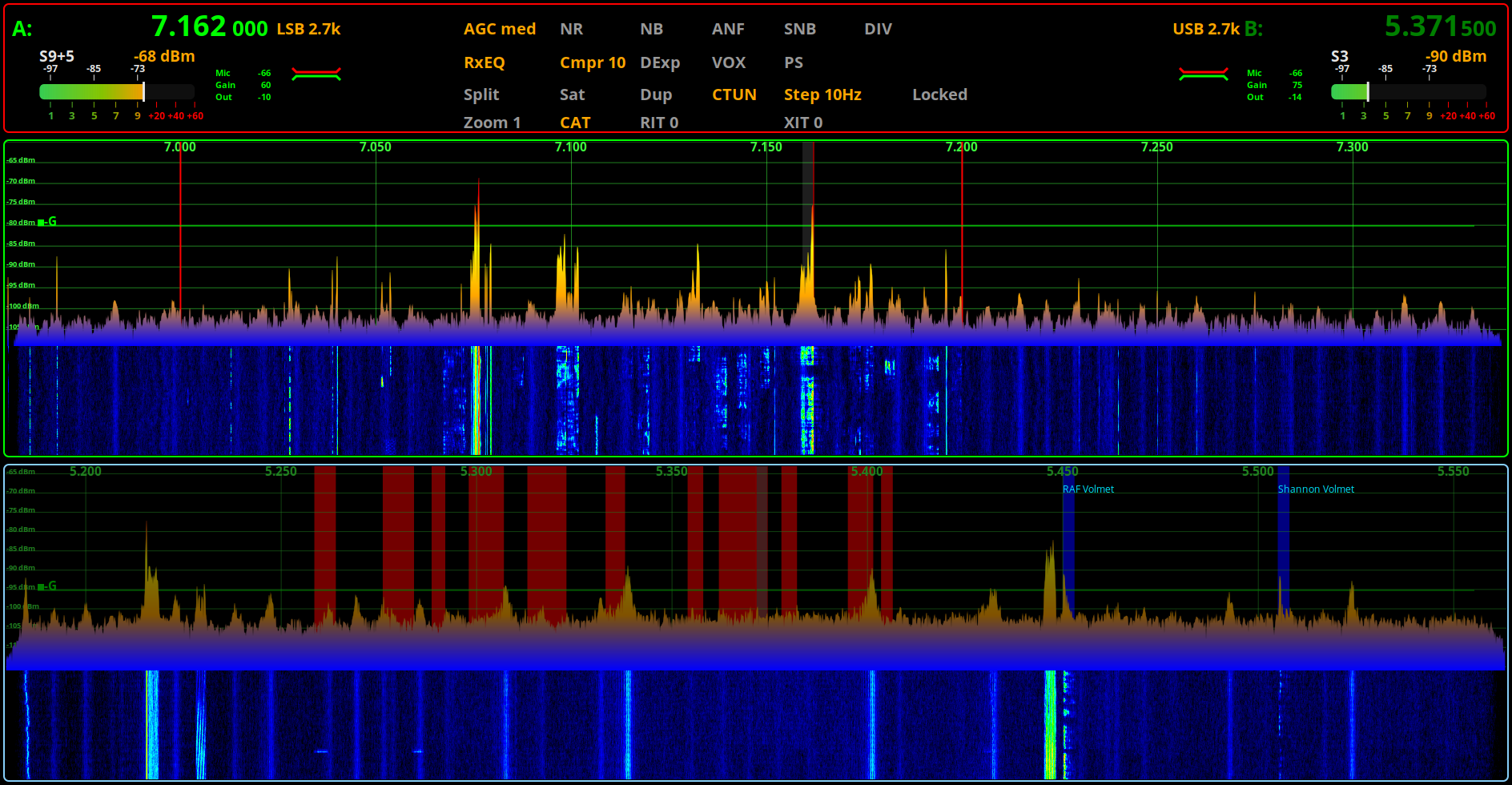
piHPSDR-Improved has also had a lot of work done to it this week with a splurge of bug fixes and enhancements being made. We decided to bring the release forward as we can then concentrate on writing the new modules to bring even more functionality to the SDR solution.
piHPSDR-Improved v2.45 in Test
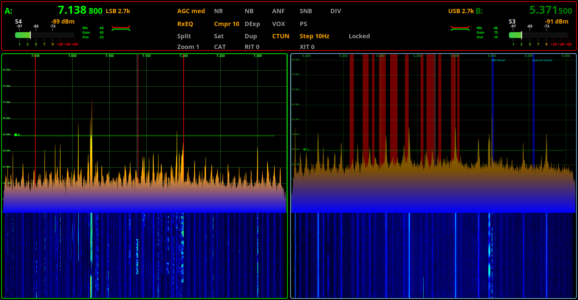
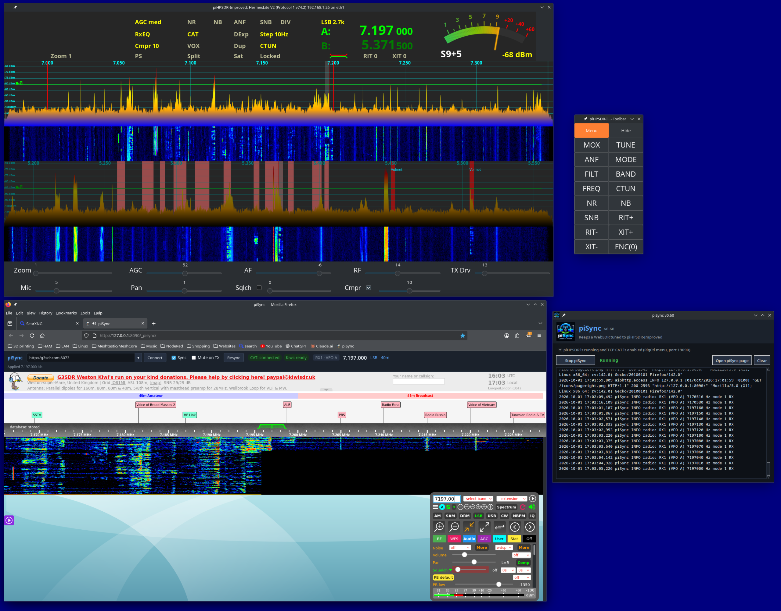
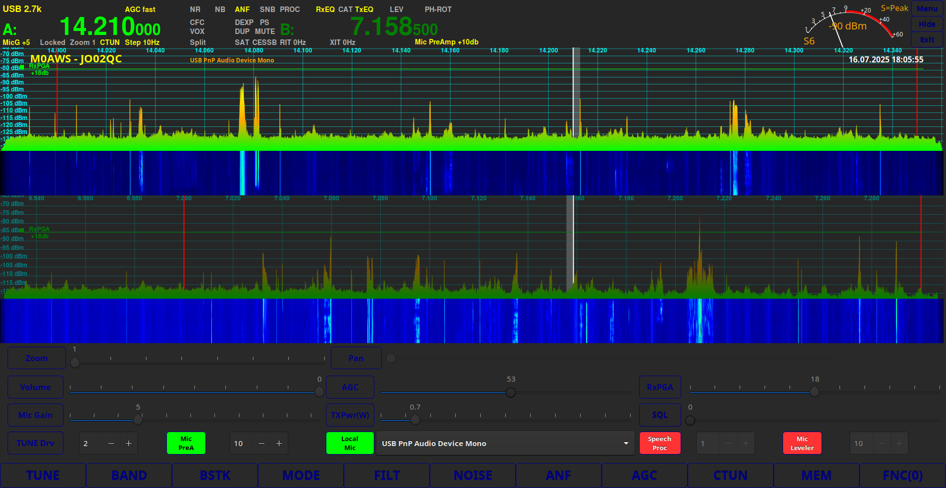
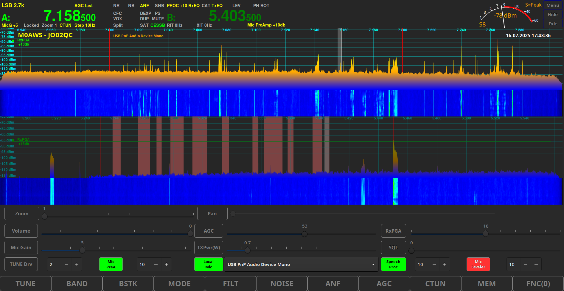
We’ve put some effort into tidying up the user interface in piHPSDR-Improved along with the new, second S Meter for VFOB. This is a really nice enhancement we’ve been wanting to do for some time but, haven’t had the time to devote to it until now.
piHPSDR-Improved v2.45 in test with Horizontally stacked RX
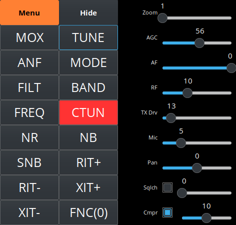
The floating toolbar has also had some upgrades and is not only looking good but, we’ve added new functionality to it as well.
piHPSDR-Improved v2.45 Floating Toolbar in Test
We’re hoping to release both of these updated software packages very soon once we’ve completed all our testing and are happy that’s it ready for release.
piHPSDR-Improved Logo from The Three Amigos Development Team
For some time now Steve (M0XVT), Alan (G1SQB) and I have been working on a version of piHPSDR to use with our Hermes Lite 2, Anan 200D, Adalm Pluto, Pluto+ and LibreSDR transceivers. The biggest problem we’ve had is the constantly changing code on github that often would stop the software from working on one device or more each time we updated and then we’d have to spend hours finding the issue and fixing it.
Eventually we got tired of this and decided to build our own stable version that doesn’t get anything from github and is made up of all the parts necessary to create a version that just works on the devices that we use on a daily basis.
Using piHPSDR on the QO-100 satellite and the HF bands across a number of very different types of hardware is a challenge in itself, especially when the devices use different protocols and only certain library sets work with certain firmware on some devices, the combinations get complicated to say the least.
To differentiate our build of piHPSDR from all the others available on the internet today we decided to call it piHPSDR-Improved.
So what is piHPSDR-Improved?
piHPSDR-Improved is a version of piHPSDR that has the fixes and enhancements in it that we’ve dreamt of having over the last couple of years. Some of the fixes are simple things like being able to detach the toolbar from the main window thus giving more space for the two panadapter/waterfall displays and have all the toolbar buttons on another screen in a floating toolbar. Other enhancements were more involved and addressed some of the most annoying issues like none of the settings for VFOB (RX2) were saved and so, every time you started the program you had to setup the RX2 all over again from scratch. These sound like simple fixes but, believe me, they’re not.
Another thing we wanted to do was make piHPSDR-Improved easy to install. Many Windows users transitioning from Windows to Linux often regret it the moment they have to use the Linux command line to install piHPSDR.
We’ve committed to having GUI installers for all the applications that we develop and release, regardless of how much extra work this entails.
It’s time installing software on Linux desktop PCs was as easy as it has been on Windows PCs for decades.
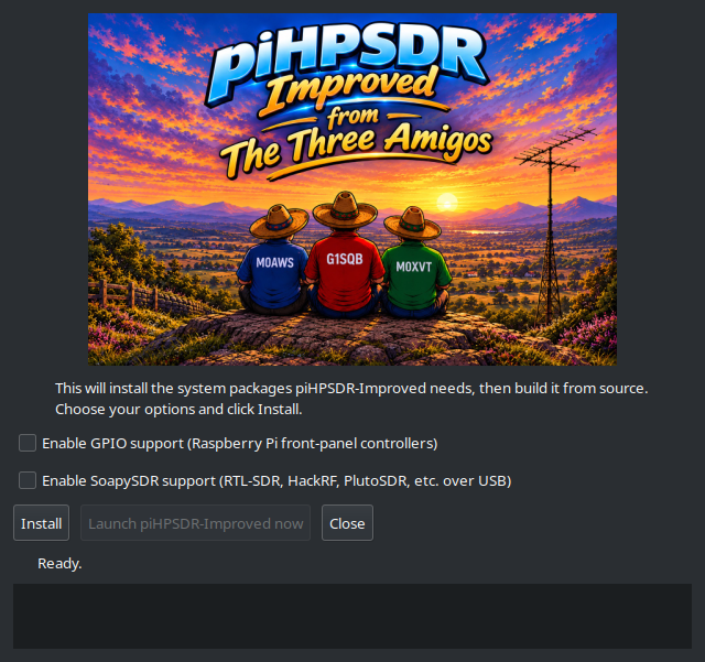
piHPSDR-Improved GUI Installer
We’ve taken a modular approach to building piHPSDR-improved. Rather than putting everything into the one application, we’re going to be releasing add on modules that will bring new functionality over time. This way we can build on a structured, stable base keeping everything operational all of the time.
The first module we’re releasing is piSync and we’ve included it in the zip file that you’ll download to install piHPSDR-Improved.
piSync Logo
piSync adds functionality to piHPSDR-Improved that Windows Thetis users have had for a long time, namely the ability to use an online WebSDR along side their own SDR transceiver and have it track the frequency, band and mode automatically. This functionality has proven to be incredibly useful when you are struggling to hear a weak DX or QRP station.
With piSync you can now use an online WebSDR receiver closer to the DX station to aid getting that QSO in the log. It’s like having another receiver in your radio that is located anywhere in the world, for free!
We believe this is a first for the Linux platform and we’re really pleased to be able to share it with the Linux community.
We’ve had great fun with piSync during testing and we think you’re all going to find it extremely useful too.
We’re also planning on adding support for FLRig in the next version of piSync so that you’ll be able to use a WebSDR with any transceiver that is supported by FLRig.
Of course it goes without saying, all of our software is Opensource. When you download and install piHPSDR-Improved or any of the new modules you will get the full source code every time and be free to do whatever you like with it. Every module will also have it’s own GUI installer, no more command line, just double click and go.
Both piHPSDR-Improved and piSync have been tested on RaspberryPi 5/500+, Linuxmint Cinnamon, Kubuntu, Debian 12 (Bookworm) and Debian 13 (Trixie) so, we’re pretty confident it’ll work on most Debian/Ubuntu based Linux distro’s on Intel/AMD PCs and the current versions of the RaspberryPi SBCs.
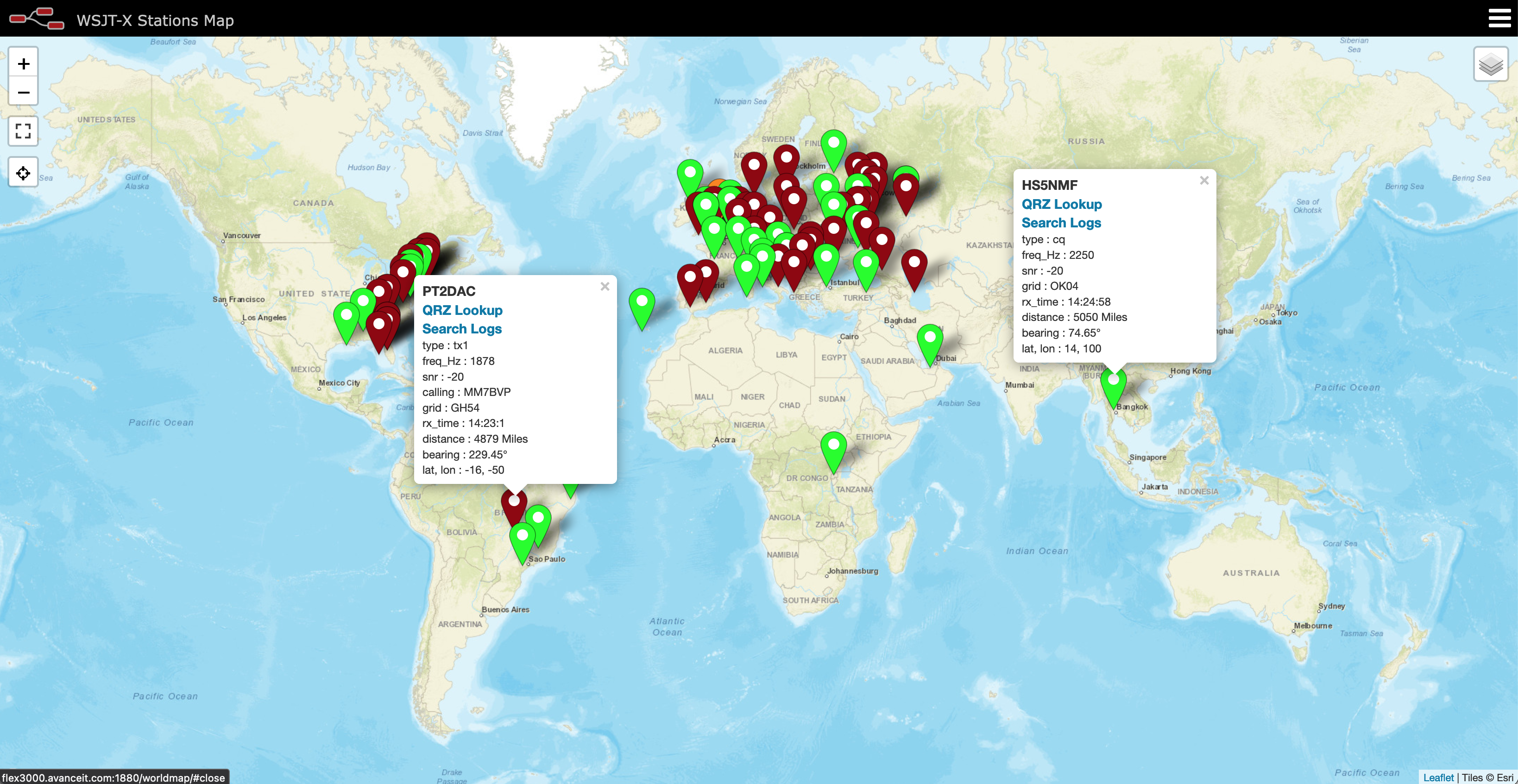
piHPSDR-Improved, piSync and a WebSDR running on a pi 500+
Inside the zip file you’ll find a file called README.1st, do make sure you read this before installing any of the software as it contains some important information that’ll make installation as easy as possible.
To download both piHPSDR-Improved and piSync in an easy to use zip file, just click the Download button below.
We’ve got lots of ideas for new features, modules and bug fixes (Yes there are still some bugs in there!) which we will be releasing over time. Don’t expect this to happen overnight as Steve still works full time and Alan and I are both enjoying our retirement.
This is just another facet of our hobby and we don’t like to rush things. We do like to use our radios on air, pretty much daily and so we do this software development in between all the other fun things that Amateur Radio has to offer.
To be clear and open we do use Claude Code to help with development. I go through as much of the code as I can without spending days and days just reading code. I am retired after all and have spent enough of my life professionally writing and debugging both my own code and other people’s code. We do a lot of testing on a good number of Linux distros before we even consider releasing the software to the wider world and use it on air as part of the testing process, so we’ve done as much as we can to ensure we’ve not introduced new bugs to the software. Keep in mind we do this as part of our Amateur Radio hobby and so, it needs to be fun and enjoyable.
We hope you enjoy using the software and find it useful. If you’ve got ideas for new things you’d like to see in future versions then please feel free to contact any of us via our contact details on QRZ.
UPDATE: We’ve fixed a little bug in piSync and released an updated version. You can download it from this article.
For some time now I’ve been using an Inverted-L style antenna, albeit not a perfect L but, I have found it to perform extremely well.
When I put the antenna up I was aiming for good NVIS radiation on 80/60/40m for chatting Inter-G and local EU stations <1000 miles from my QTH.
I wasn’t expecting good performance on the higher HF bands as the total length of wire is 37m which is somewhat long for the higher frequency bands however, I’ve found performance around Europe to be very good and extremely good over the north pole to Oceania and the USA.
M0AWS Inverted-L style Antenna
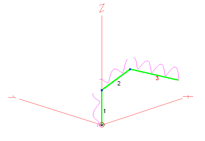
As you can see from the antenna view above, it’s not a perfect inverted-L by any means however, its shape has actually proven to be advantageous.
Wire 1 is 9m tall, it then goes approximately 10.5m in length up to a peak of 12m above ground in the centre, this is where I have a 12m Spiderpole for support. From there the remaining 17.5m of wire slopes down to 5m above ground and is attached to the back of the house via a large insulator. Total wire length is 37m.
Wire 1 is at the bottom of a South facing garden and direction +X is north.
The antenna is tuned at the bottom of wire 1 using my CG3000 Remote Auto ATU at ground level. There are a number of random length radials hidden in the lawn and around the perimeter of the garden running mainly from South to North. I cannot run any radials to the south (-X) as this is farmland and not owned by me.
On the low bands I find it has great NVIS performance with excellent signal reports from all over the UK and out to around 1500 miles into Europe and beyond. This is exactly what I wanted from the antenna and I’ve been very pleased with it’s performance on 80/60/40m.
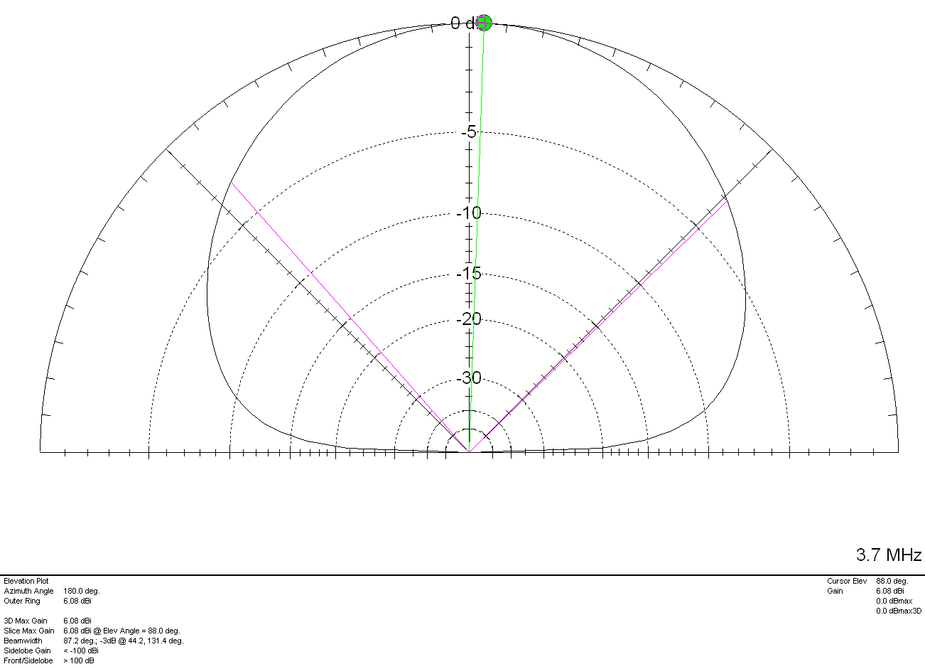
Looking at the 2D Far Field Plots on the 3 low bands the antenna has a typical NVIS high angle of radiation pattern with some gain.
M0AWS Inverted-L Style Antenna 2D Plot on the 80m Band
On the 80m band maximum radiation is straight up, as expected with a gain of 6.08dBi (3.58dBd). The gain reduces at lower angles however, it still performs well out to around 1500 miles and occasionally even further.
M0AWS Inverted-L Style Antenna 2D Plot on the 60m Band
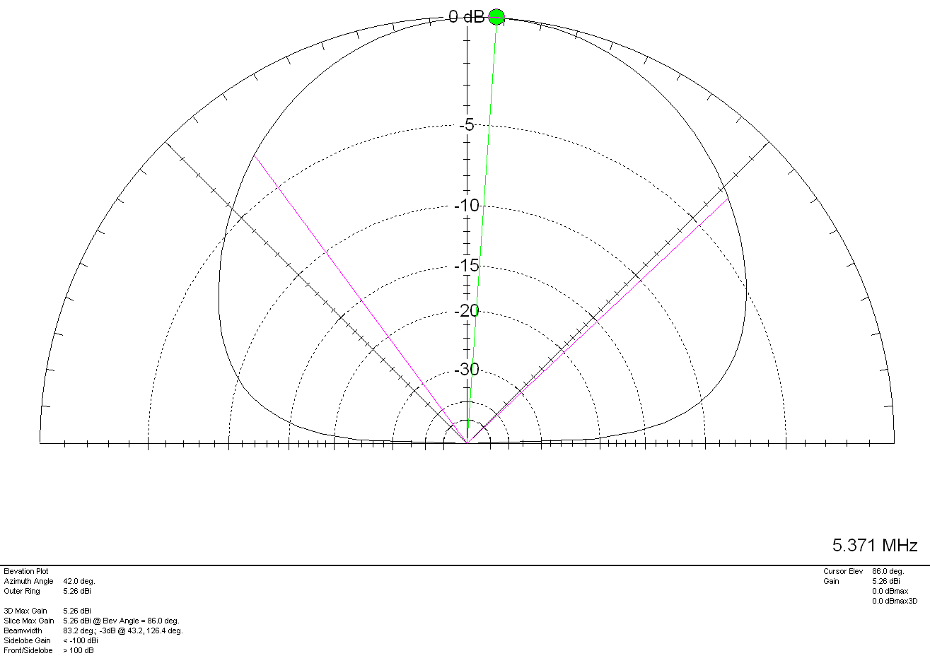
Once again on the 60m band maximum radiation is pretty much straight up as expected however, I have worked in to Canada many times on 60m with excellent signal reports and so, it also has good DX capability too. With 5.26dBi (2.76dBd) gain it’s not a lossy antenna by any stretch of the imagination.
M0AWS Inverted-L Style Antenna 2D Plot on the 40m Band
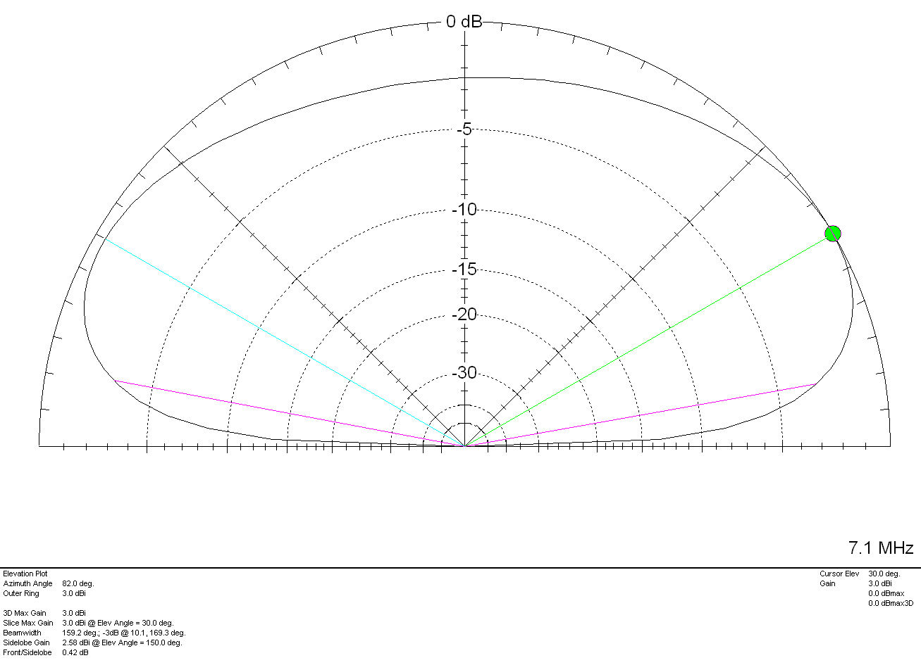
On the 40m band things start to change a little with the angle of maximum radiation being at 30 degrees rather than straight up. This gives the antenna “longer legs” on the 40m band making it very easy to work longer distances. It’s still very good for Inter-G but, performance over longer distances is considerably better. With a gain of 3.0dBi (0.5dBd) it’s performance is similar to that of a dipole at a similar height above ground.
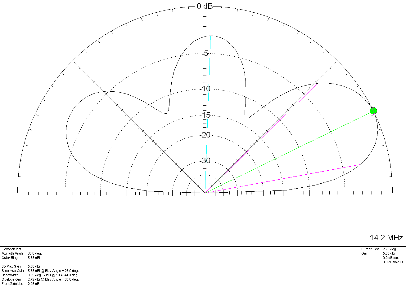
Above 7Mhz things start to change considerably. The antenna becomes directional to the North West (NW) and North East (NE) giving excellent DX results over the North Pole into North America and Australia/New Zealand. The antenna does of course also have an element of high angle radiation making it useful into Europe and North Africa on the higher bands.
M0AWS Inverted-L Style Antenna 2D Plot on the 20m Band
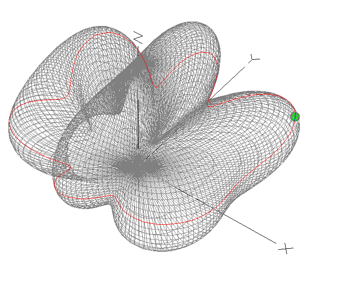
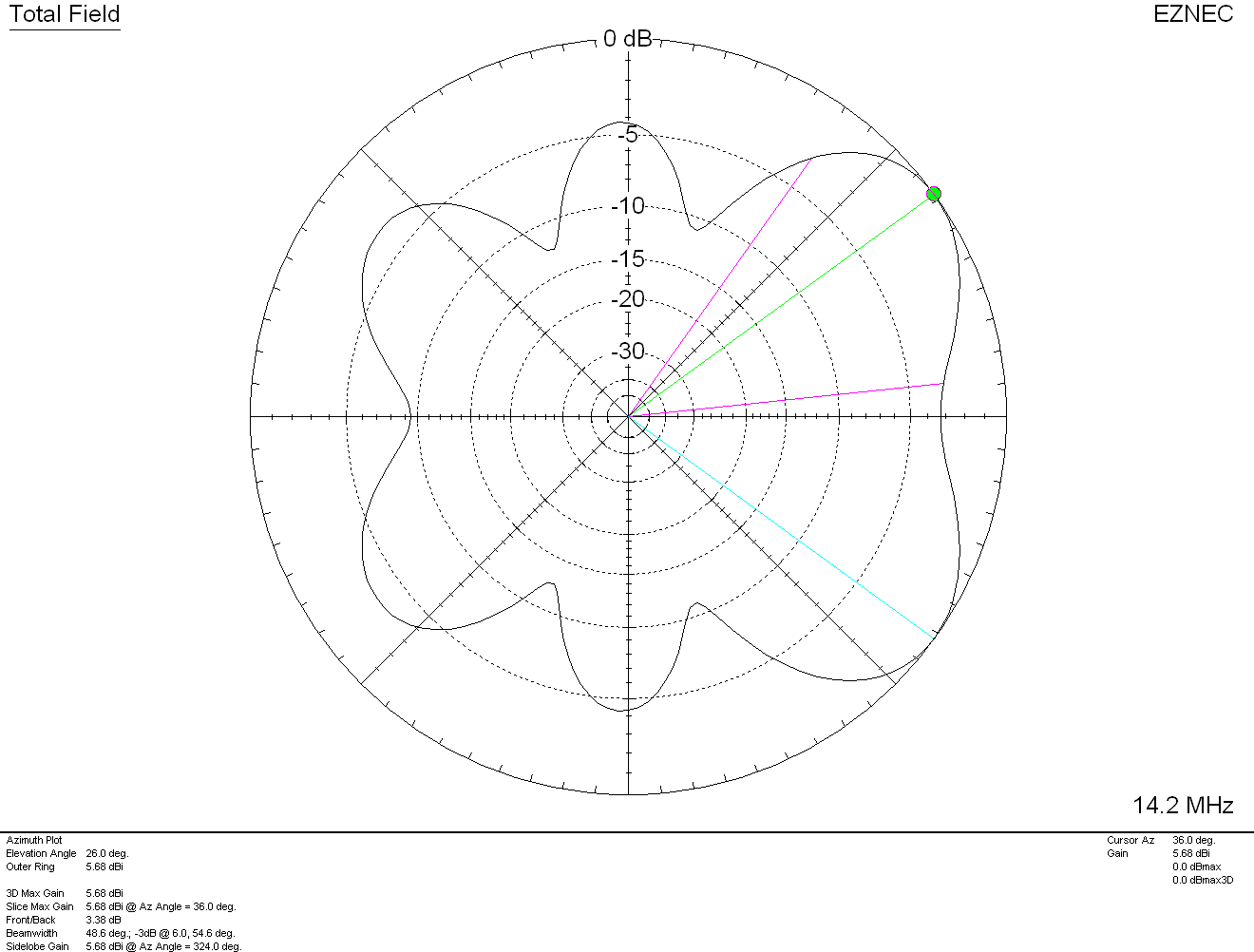
On the 20m band the maximum radiation is at 26 degrees with a gain of 5.68dBi (3.18dBd) pointing NW and NE. There is a lower gain lobe to the South West (SW) and South East (SE) giving excellent coverage through Europe and into Africa as can be seen in the 3D Far Field Plot and Azimuth Slice shown below.
M0AWS Inverted-L Style Antenna 3D Plot on the 20m BandM0AWS Inverted-L Style Antenna 2D Azimuth Slice on the 20m Band
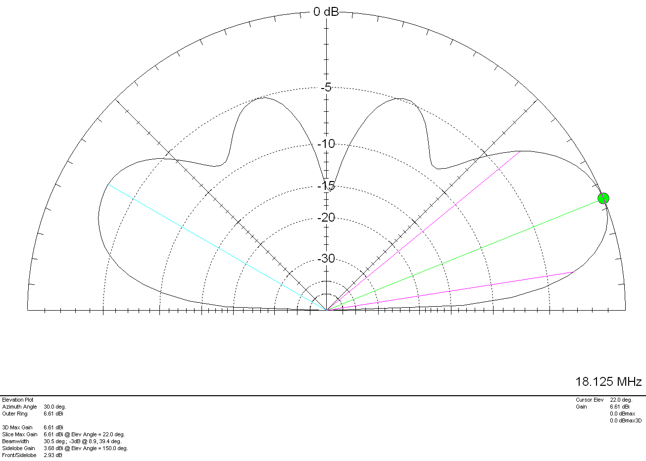
Moving up in frequency to the 17m band the 3D Plot and Azimuth Slice are similar to that on the 20m band but, with a slightly lower angle of maximum radiation and slightly more gain as can been in the 2D elevation plot shown below.
M0AWS Inverted-L Style Antenna 2D Plot on the 17m Band
With a gain of 6.61dbi (4.11dBd) at 22 degrees to the NW and NE and slightly lower gain and higher angle to the SW and SE the antenna has proven to work extremely well on the 17m band. My best DX on 17m so far has been a QSO with Eric, FK8GM in New Caledonia some 10230 miles from my QTH using just 80w of SSB.
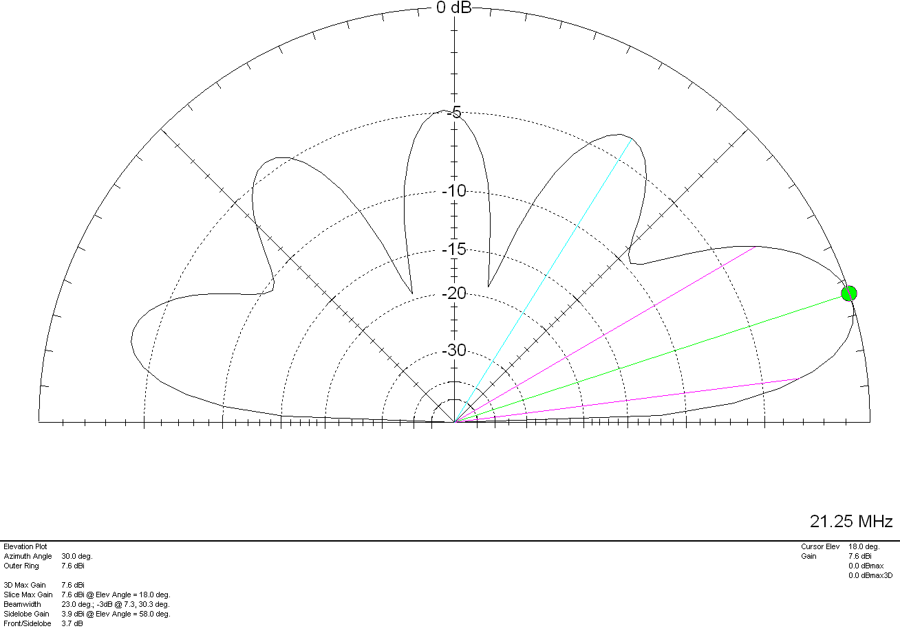
The 15m band is a similar story, 7.6dBi (5.1dBd) at just 18 degrees pointing NW and NE. This antenna works extremely well into North America and Oceana (I’ve also worked FK8GM on 15m too). Once again there are lower gain lobes to the SW and SE at a similar angle along with some high angle radiation that aids coverage into Europe. The antenna really is a great all rounder on the 15m band.
M0AWS Inverted-L Style Antenna 2D Plot on the 15m Band
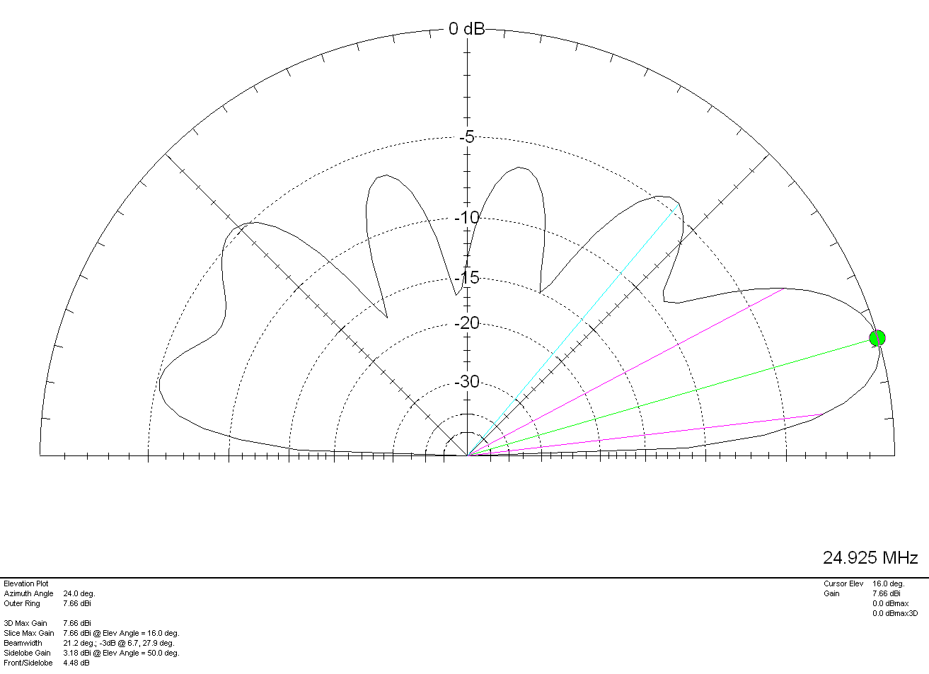
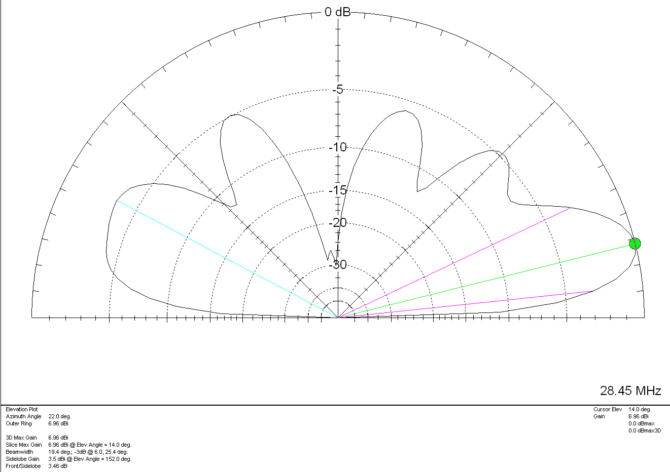
The 12m and 10m bands are a similar story, low angle, high gain lobes to the NW and NE with lower gain coverage to the SW and SE.
M0AWS Inverted-L Style Antenna 2D Plot on the 12m Band
On 12m the antenna has a very respectable gain of 7.66dBi (5.16dBd) at a low 16 degrees pointing NW and NE making it a great DX antenna. Once again, higher angle lower gain lobes to the SW and SE.
Finally on the 10m band the antenna has a gain of 6.96dBi (4.46dBd) at a very low angle of 14 degrees to the NW and NE. If DXing over the pole on the 10m band is your thing then this simple antenna will certainly help you along and maybe even put a smile on your face.
M0AWS Inverted-L Style Antenna 2D Plot on the 10m Band
For such a simple antenna that will fit easily into many typical UK gardens I have been extremely pleased with it’s performance. Whether I’m gassing on the low bands with friends from the Matrix rooms or chasing DX on the higher bands, the antenna has put a smile on my face time and time again.
On receive the antenna is surprisingly quiet, with an S3-4 background noise on the 80/60/40m bands through to less than 1 S point of noise on the higher bands. Picking out the weak DX stations really isn’t a problem.
It just goes to show that you don’t need to spend a fortune on commercial antennas to work the world on the HF bands. With as little as 80w of SSB and a piece of wire connected to a remote ATU you can have just as much fun as the big boys!
The articles I write for the blog are mostly technical but, I thought it was about time that I wrote this article as it’s been buzzing around inside my head for some time now.
So, what are the 5 things that I have found revolutionary in my shack that have brought new, exciting ideas and projects to life making amateur radio more enjoyable.
1: A RaspberryPi Single Board Computer
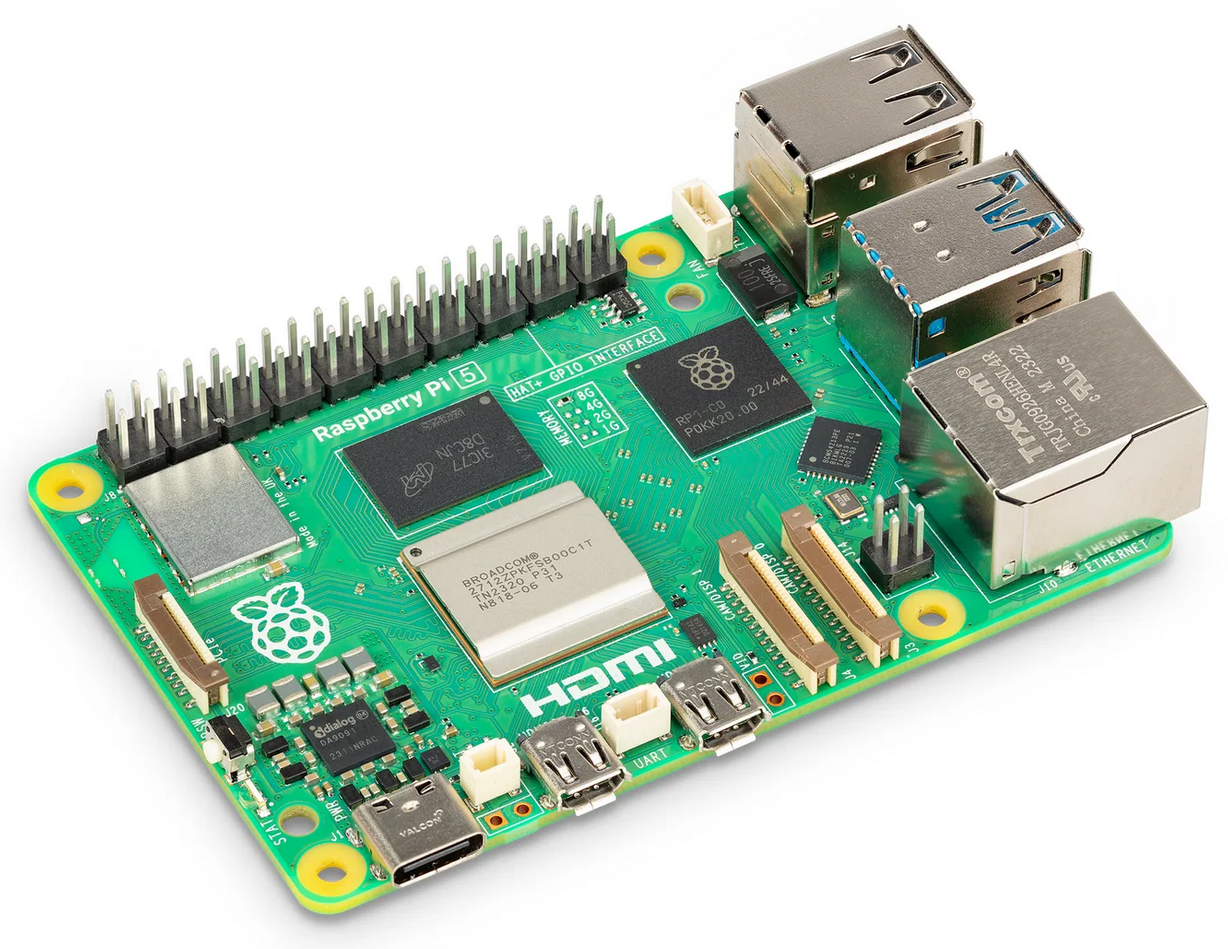
RaspberryPi 5 Single Board Computer
Ever since the first RaspberryPi Single Board Computer (SBC) was released I’ve been a huge fan. This little credit card sized number cruncher has been the base for so many projects, it has to be the first on my list.
The RaspberryPi SBC has been through a few iterations since its initial conception and is now powerful enough to take on most tasks that any radio HAM is going to throw at it.
So, what have I done with them?
Well I’ve used them to run Node-Red services for my many web app dashboards that control things like my QO-100 Satellite Ground Station, UPS power monitoring, Internet speed graphs, server and virtual machine monitoring, AllStarLink nodes, hosting websites, building an SDR shortwave receiver, running HAM Clock / Open HAM Clock, developing my own software, hosting virtual machines and a whole host of other fun and interesting things. I’m even writing this article using my RaspberryPi 500+ computer that is my daily desktop PC.
There are an endless number of things you can do with a RaspberryPi to bring new life and functionality to your radio hobby.
Want to get into Amateur TV? Want to decode digital modes real time? Want to track aircraft in the sky real time on a virtual radar screen? Want to search the shortwave bands for stations of interest? Want to host your own blog and website?
All these things and a lot more are easily within reach with a RaspberryPi.
The RaspberryPi is only limited by your imagination, the more imaginative you are the more your number crunching little friend will do.
2: A 3D Printer
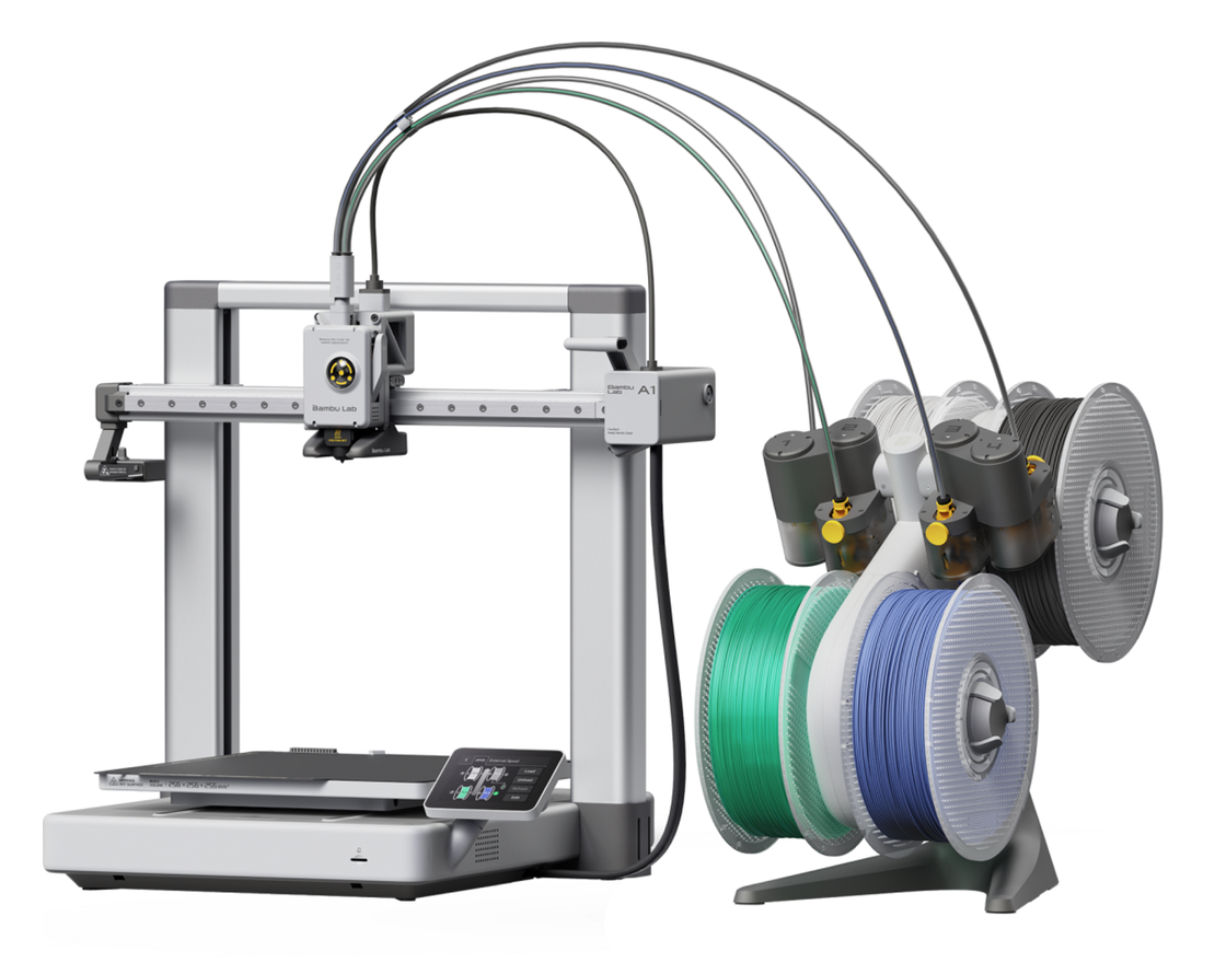
Bambu Lab A1 Combo 3D Printer
Every HAM should have a 3D printer. These manufacturing marvels bring a new level of quality, design and simplicity to your HAM radio projects. I’ve found it incredibly useful since venturing into the rabbit hole that is 3D printing. When I think back to the weeks and months of my life I’ve spent making cabinets and boxes out of sheet metal, aluminium or wood for the numerous projects I’ve built over the years, a 3D printer would had made my life so much easier. 3D printing has revolutionised the making of things for the Amateur Radio home brewer.
There’s a multitude of useful things on websites like Printables, Thingiverse , Makerworld and others where you can just download the files and print high quality designs for all those things you’ve wanted to do but, don’t have the time or inclination to craft by hand.
The real satisfaction with 3D printing comes from designing your own things and making them. My first project was to design and print a fan cooling system for my Xiegu XPA125B amplifier.
From the factory the amp is passively cooled and doesn’t take long for the heat-sink to become saturated resulting in a high operating temperature. I was never happy with this and so was determined to resolve the problem.
Getting to grips with TinkerCAD was a bit of a vertical learning curve but, after a few mistakes and design mishaps I soon had it under my belt and pressed on with designing the cooler unit.
Designing the Xiegu XPA125b cooling system using tinkerCAD.
It’s not until you start designing and manufacturing things that you suddenly realise how much effort goes into them but, I persevered and over the period of about a week or so I had a perfectly fitting, operational cooling system that kept the amp super cool regardless of how long I waffled on for on the HF bands.
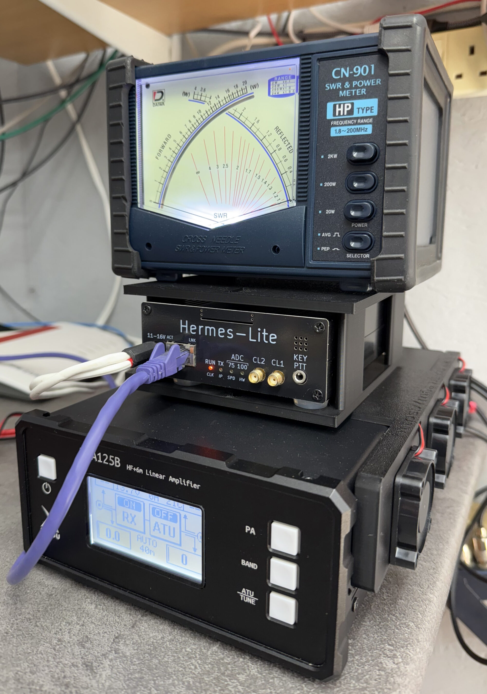
Once you’ve got your first design made you suddenly find yourself wanting to improve it and add things. In my case this was adding a Hermes Lite 2 holder to the top of the amp cooler and then a top shelf to hold my cross needle SWR and power meter.
Since then I’ve progressed massively with my designs and have even designed and printed things for other HAMs and family members, it’s totally addictive!
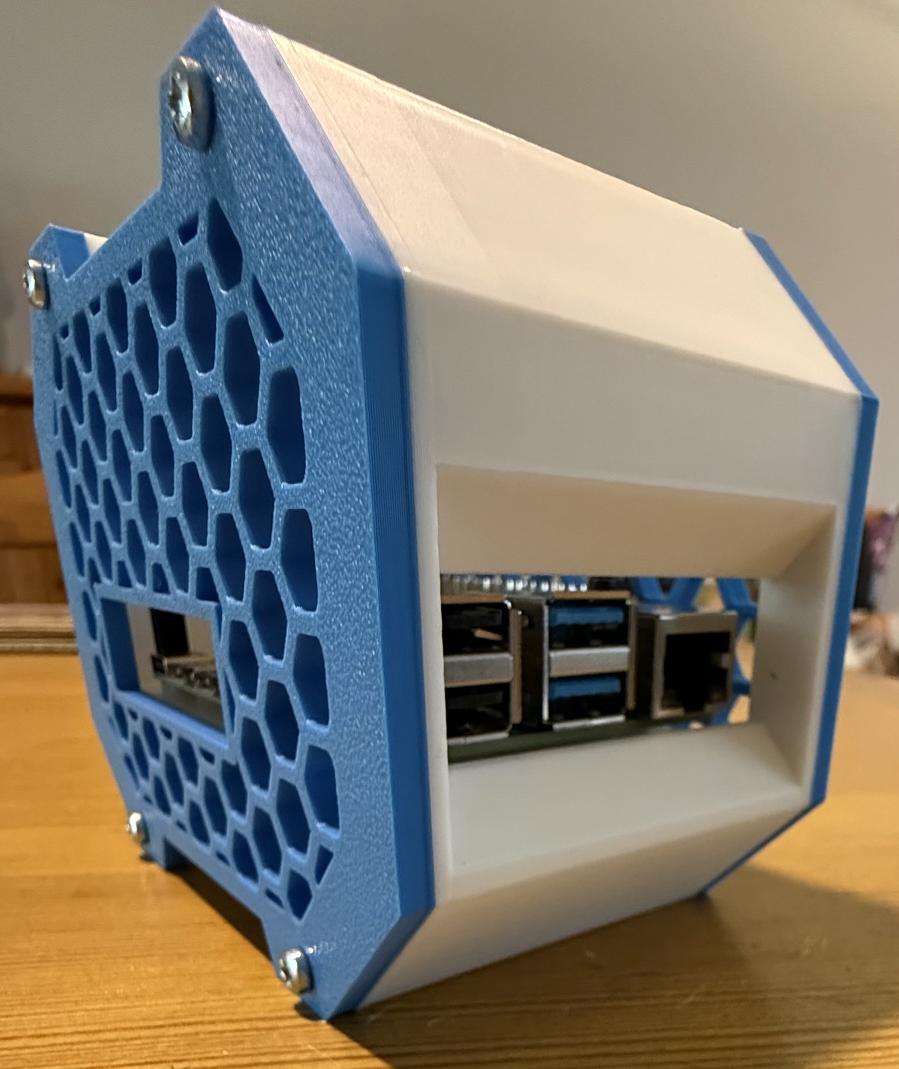
I can highly recommend the Bambu Lab A1 Combo (As shown above). It’s a quality piece of equipment that has operated faultlessly since purchase. Right now it’s printing a case for my RaspberryPi 4, just one of the many projects I’ve used it for since becoming a happy owner.
RaspberryPi 4 case from printables.com
Go on, release your inner creativity and treat yourself to a 3D printer, you won’t regret it and it’ll help you bring to life all of those radio projects you’ve dreamt of doing but, never got round to starting.
3: An AllStarLink Node
M0AW AllStarLink Node 61928 sitting on the equipment rack
Many people say that using VOIP over the internet isn’t real radio, I know because I used to be one of those people however, it has become an invaluable resource for keeping in touch with people all over the world.
Being part of an online HAM Radio Community it’s important that as a group we are able to talk to each other regardless of where we live, what bands we have access to and whether there is any propagation.
The AllStarLink (ASL) network gives global FM quality audio no matter where you are in the world. We use it daily for our breakfast net, general chatter throughout the day and even hold a weekly Matrix ASL Net on a Thursday evening.
Using our VHF/UHF handhelds (Real Radios!) and an easy to make AllStarLink Node we’re able to join in with the conversation regardless of propagation, licence type or distance, it really is great for bringing people together.
With devices like the SHARI and AIOC board now being readily available for minimal cost it really is very easy to get onto the AllStarLink network and talk to people even if you live in an antenna restricted location.
Why be alone when you can use the Matrix ASL node ( 642332 ) and join in the conversation.
4: Node-Red
M0AWS – Updated NodeRed QO-100 Dashboard with PTT button
Node-Red is a low-code programming tool for event-driven applications.
Node-RED’s goal is to enable anyone to build applications that collect, transform and visualise their data; building flows that can automate their world. Its low-code nature makes it accessible to users of any background, whether for home automation, industrial control systems or anything in between.
I’ve been using Node-Red for a number of years now and have developed a suite of web app’s that control and monitor just about every aspect of my Amateur Radio hobby and IT infrastructure.
Node-Red forms an integral part of my QO-100 Satellite Ground Station providing control of both the uplink and down link radios whilst synchronising the VFO’s, controlling filter selection and more, all from one simple to use interface using nothing more than a web browser.
It doesn’t stop there, my AllStarLink (ASL) nodes are also managed through a user friendly Node-Red Dashboard that removes all the need for technical know how and makes ASL node management as simple as clicking on a button to connect or disconnect to the many global networks.
Much of this functionality is achieved without writing a single line of code. If you can use a mouse, drag and drop objects on the screen you can develop Node-Red web app’s, it really is that easy.
M0AWS Interactive Log Flow
It doesn’t end there, Node-Red is great for presenting data in easy to digest formats.
Whether it be HAM Radio Log data presented on an interactive world map or monitoring of your server, RaspberryPi, virtual machine or UPS using gauges and graphs, this can all be achieved easily with nothing more than a mouse. There’s no need to spend hours writing thousands of lines of code, just drag and drop a few nodes onto the screen and join them up. You’ll be amazed how easy it is.
I believe every Amateur Radio enthusiast should have Node-Red available in their radio shack. It’s easy to install on your RaspberryPi 4 or 5, Linux or Windows PC and Apple Mac with the same great functionality available on all platforms.
Once you’ve developed your first web app you’ll suddenly find a million more ideas will come into your head and before you know it, you’ll be where I am today with Node-Red at the centre of your radio hobby.
5: A Hermes Lite 2 HF SDR Transceiver
For years I used black box HF radios from the big 3 manufacturers along with the odd radio from the smaller enterprises like TenTec but, they all had their foibles and there was often nothing I could do about it.
My last acquisition from the big 3 was a Yaesu FTDX10, a competent hybrid SDR radio with a good receiver however, the menu system is terrible, the button layout not much better and the user experience not as good as it could be. Of course the software is closed source so there is nothing you can do about it. The radio did its job but, it wasn’t fun to use, it wasn’t what I really wanted and it didn’t put a smile on my face.
I looked at moving to software defined radios (SDR) but, with prices in the many thousands of pounds bracket and the software being closed source I came to the conclusion that they wouldn’t give me what I really wanted either.
So what was it that I was searching for?
Thinking long and hard about it I came to the conclusion that what I really wanted was a radio that gave me the same satisfaction that OpenSource software has given me for decades, namely an HF radio that I have complete control over, from the hardware through to the software and everything in between.
I wanted something that I could tailor to my exact needs. Something that was built using open hardware and open software, something where if I wasn’t happy with it I could change it, improve it and do the things I wanted with it.
At this point my search for the ideal radio headed in a completely different direction.
Xiegu XPA125b Cooler with Hermes Lite 2 cradle – front view
The Hermes Lite 2 SDR HF Transceiver (HL2) has been around for a number of years. I was first introduced to it by Michael, DK1MI and then Roger, G8VLR via the Matrix. Both Michael and Roger use the HL2 on a regular basis and have often waxed lyrical about how good it is.
Being designed by radio amateurs for radio amateurs it’s based on an open architecture from the ground up. Being an OpenSource junky this really appealed to me and as I looked deeper into it from both a hardware and software point of view I soon realised that it had the potential to be exactly what I was looking for.
It wasn’t long before I found myself on the Makerfabs website placing an order for the HL2 mainboard, filter board, I/O board and case. A couple of weeks later it arrived and I dived head first into the SDR rabbit hole.
2 years later and the HL2 has become my main HF radio in the shack. Partnered with a Xiegu XPA125B amplifier and PiHPSDR software running on my Kubuntu Linux PC it is everything I have been looking for in an HF radio.
I’ve made modifications to the software to suit my operating style and needs with the user interface being exactly how I want it, no unnecessary buttons or knobs, just the controls that I use on a daily basis cleanly placed in a logical, easy to use layout, the way I want it.
My understanding of software defined radio and how it works has improved a hundred fold. Having access to the software and being able to go through the code and understand the architecture has been an interesting journey and one that has enhanced my radio enjoyment considerably. I now have a smile on my face every time I go on air.
Do I miss the FTDX10?
No, not in the slightest!
So, those are the 5 things that I feel have revolutionised my radio amateur hobby and made it a more enjoyable experience. I’m sure over time I will add to this list as I venture down future rabbit holes in our wonderful radio hobby.
I’m sure there are many radio amateurs around the world today who have an old handheld radio sat on the shelf that works perfectly but, has been replaced by a new, shiny, all singing, all dancing model that gets used on a daily basis. I for one have fallen into this trap with the recent purchase of a very nice Wouxun KG-UV9K full duplex 2m and 70cm handheld.
On my shelf there is a cheap Retevis RT85 that gave sterling service for a number of years and even today is ready to continue that service, if only I had a need?
Well now I do!
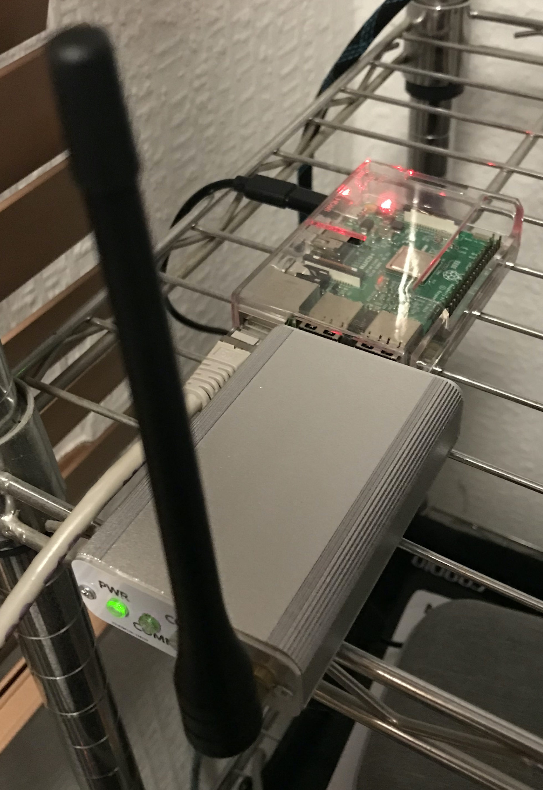
Currently I have an AllStarLink node running on a RaspberryPi 3b connected to a SHARI device that operates on the 70cm band. This node works great and gives me the ability to chat with people all over the world from my trusty handheld. It does of course also give me access to the weekly Matrix AllStarLink Net that happens on our Matrix node ( 642332 ) every Thursday evening at 20:00 UK time, a great way of bringing the Matrix HAM Radio community together regardless of propagation.
For some time I’ve been wanting to bring another AllStarLink node online so that I can have a connection to HUBNET/FreeNet whilst keeping my current node connected to the Matrix node for our regular daily chats. Since my new Wouxun handheld is a full duplex unit it makes sense to bring a new node up on the 2m band as I can then monitor both at the same time easily. I do have a spare SHARI node however, it’s a UHF only unit and I don’t want another node on the 70cm band. This is where the old Retevis RT85 comes in to play.
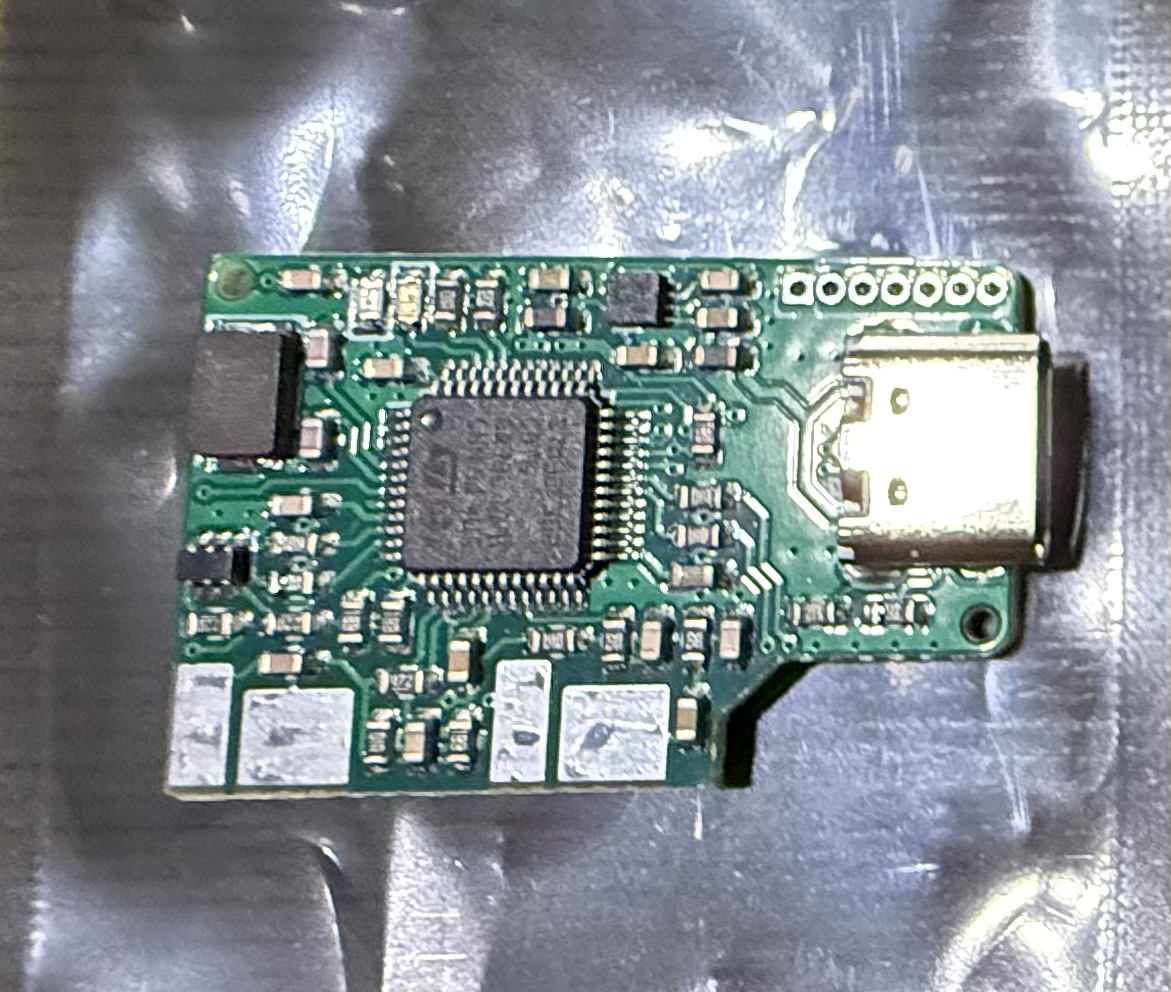
The AIOC board really is tiny but, beautifully put together. The four large solder pads on the top and more on the underside are positioned such that the TRS plug solder lugs line up perfectly for soldering. Attempting to do this by hand would be impossible as it’s critical that the spacing between the two connectors matches that of the spacing of the sockets on the radio.
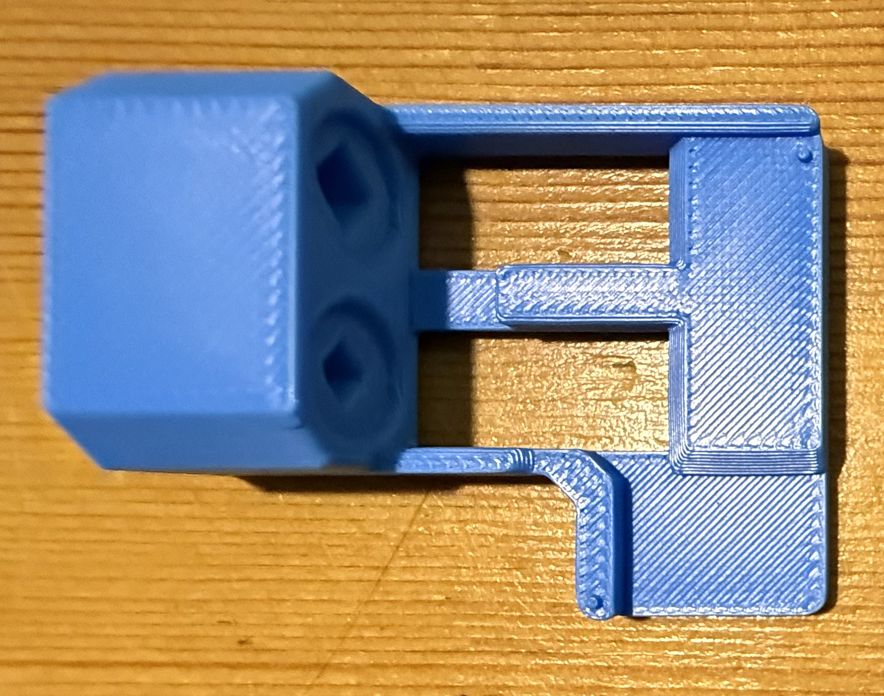
AIOC Solder Jig.
Searching online I found a very handy soldering jig on Github that enables you to hold both the TRS connectors and AIOC board in the perfect position for soldering.
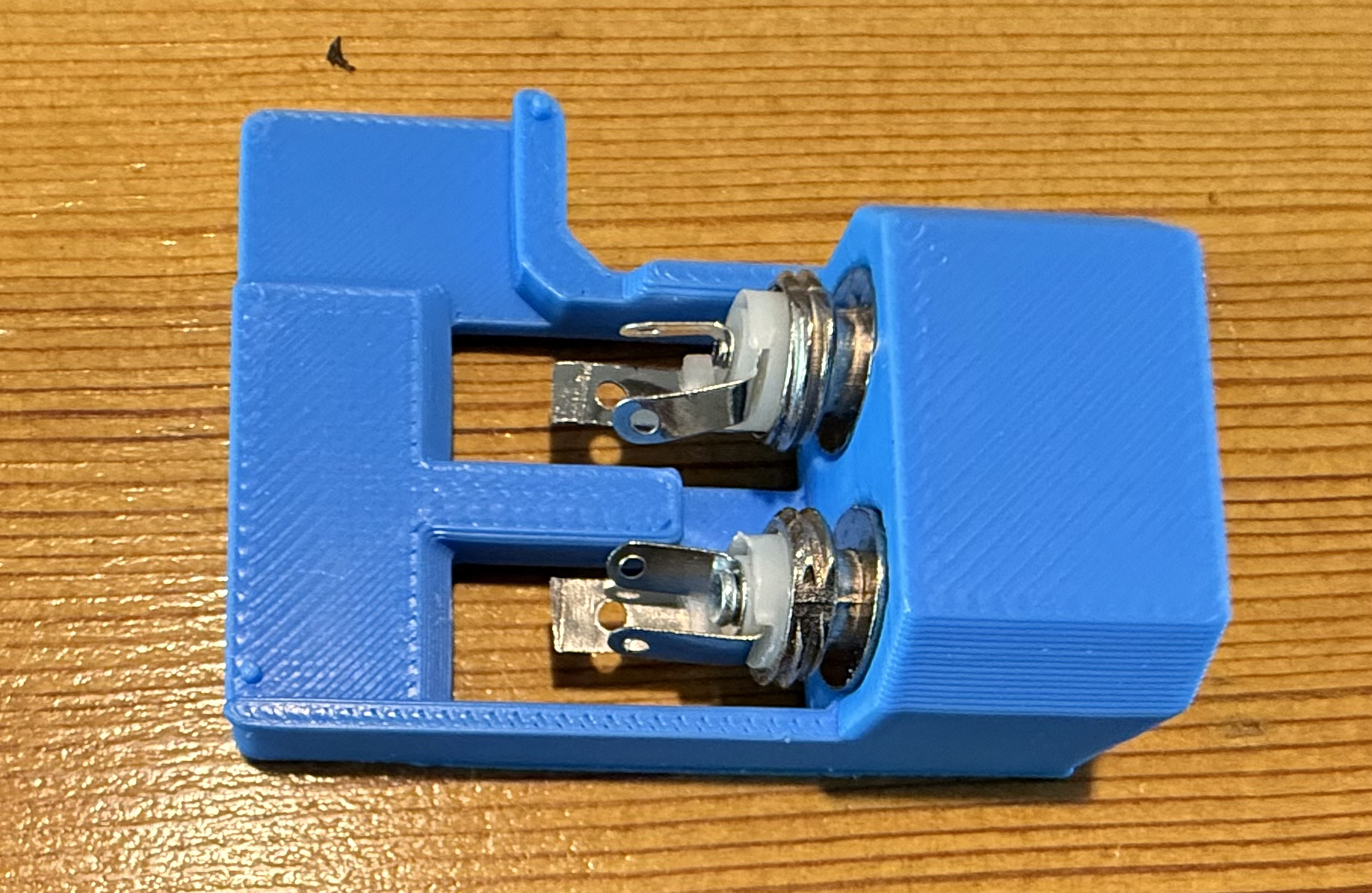
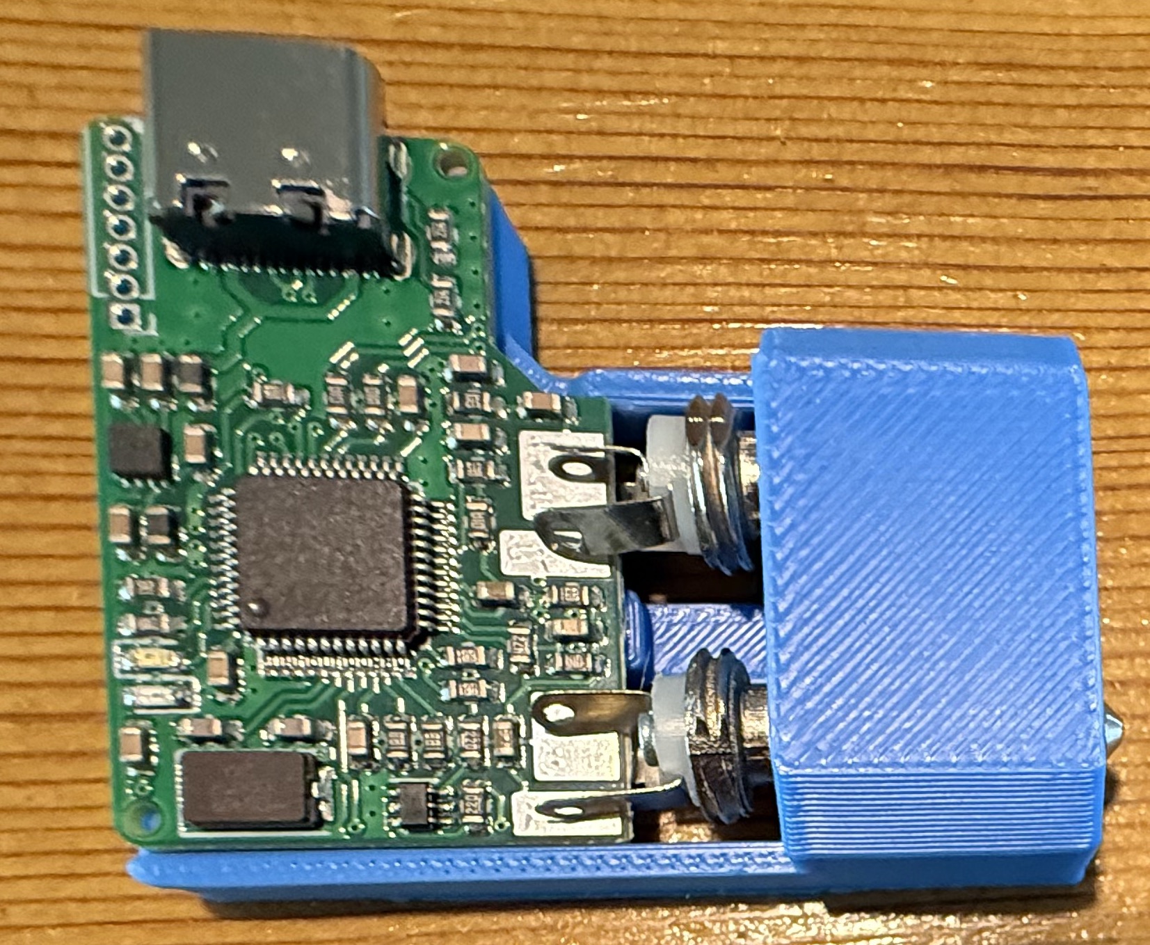
Downloading the .STL file I quickly printed off a solder jig on my Bambu Lab A1 Combo 3D printer and fitted the components into place ready for soldering.
Fitting TRS connectors into the AIOC solder jigFitting AIOC board into the solder jig.
Everything fitted rather snugly into the jig and I soon had the board and connectors soldered together. Test fitting to my Retevis RT85 I found the TRS plugs lined up perfectly and it slid into the sockets with ease.
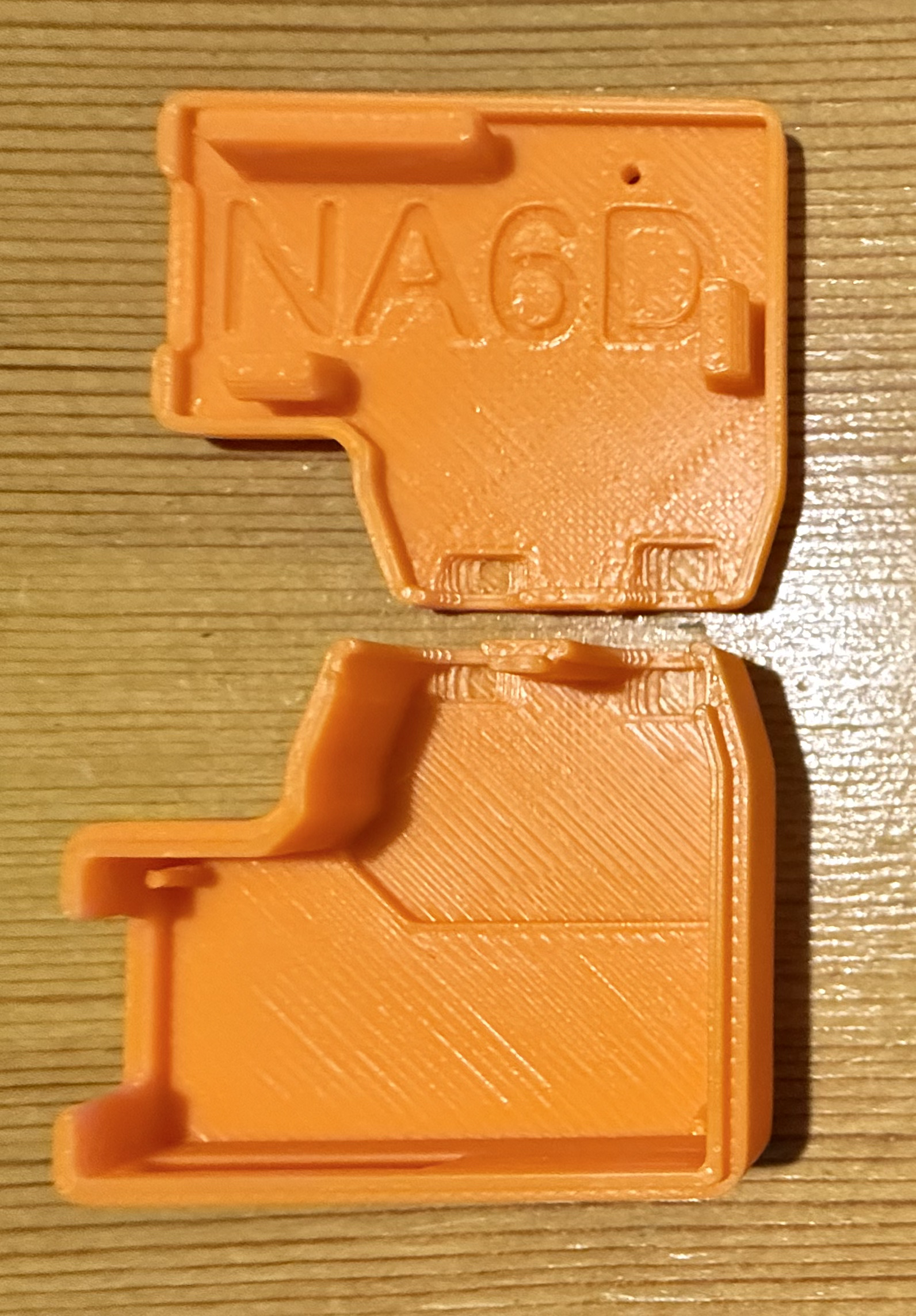
I then thought about designing a case for the AIOC board so that the bare circuit was nicely protected but, quickly searched online and found that NA6D has already designed a case and made the .STL available publicly for download on Printable.com. I quickly grabbed a copy of the file and punted it off to my 3D printer to get to work on.
3D print NA6D AIOC case.
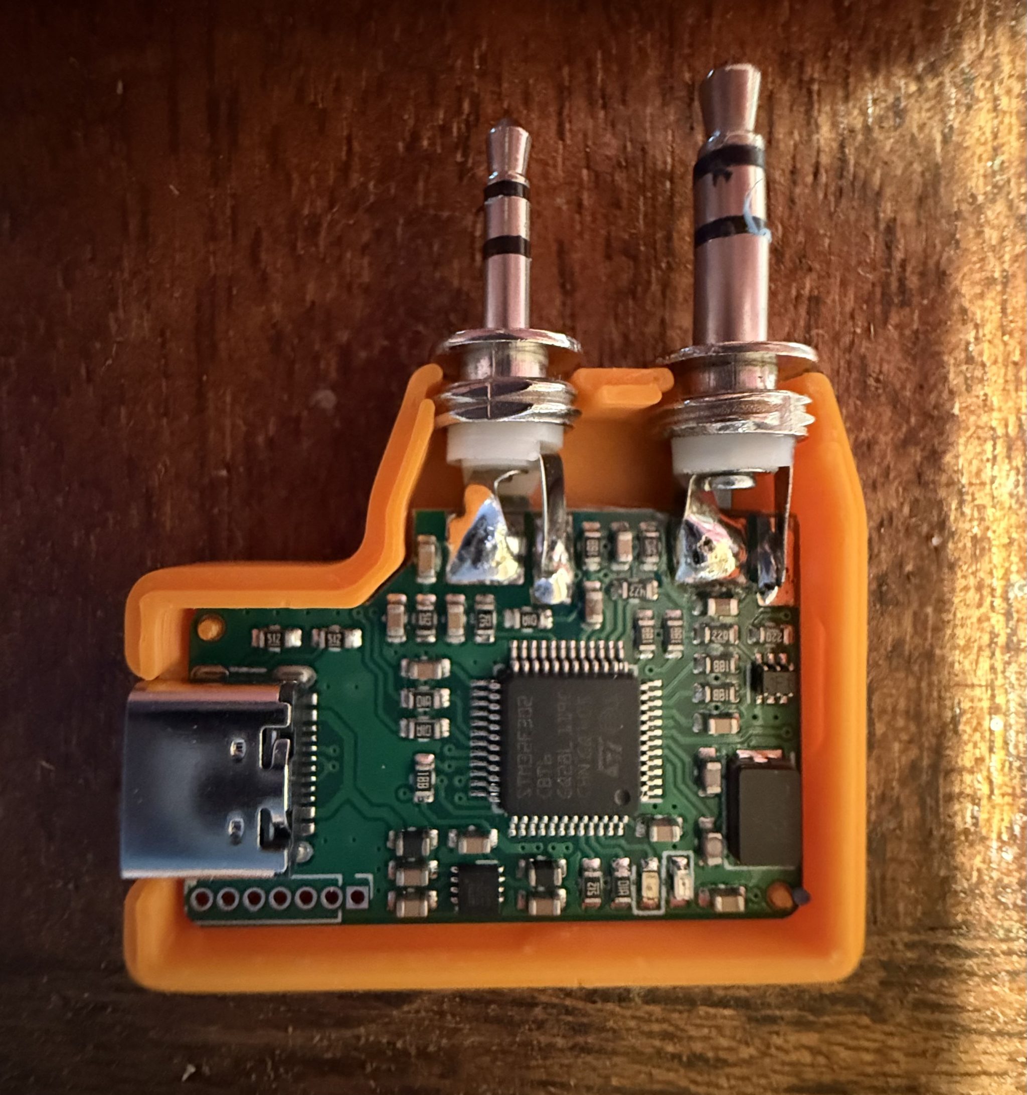
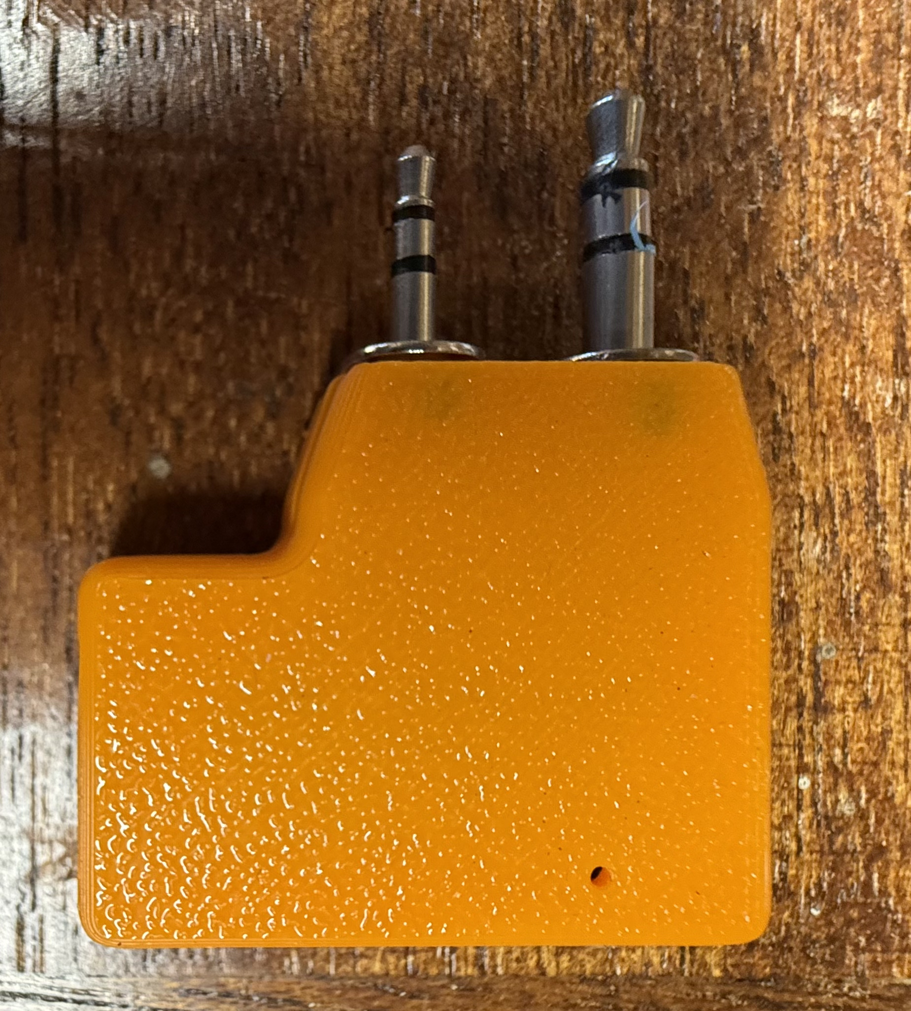
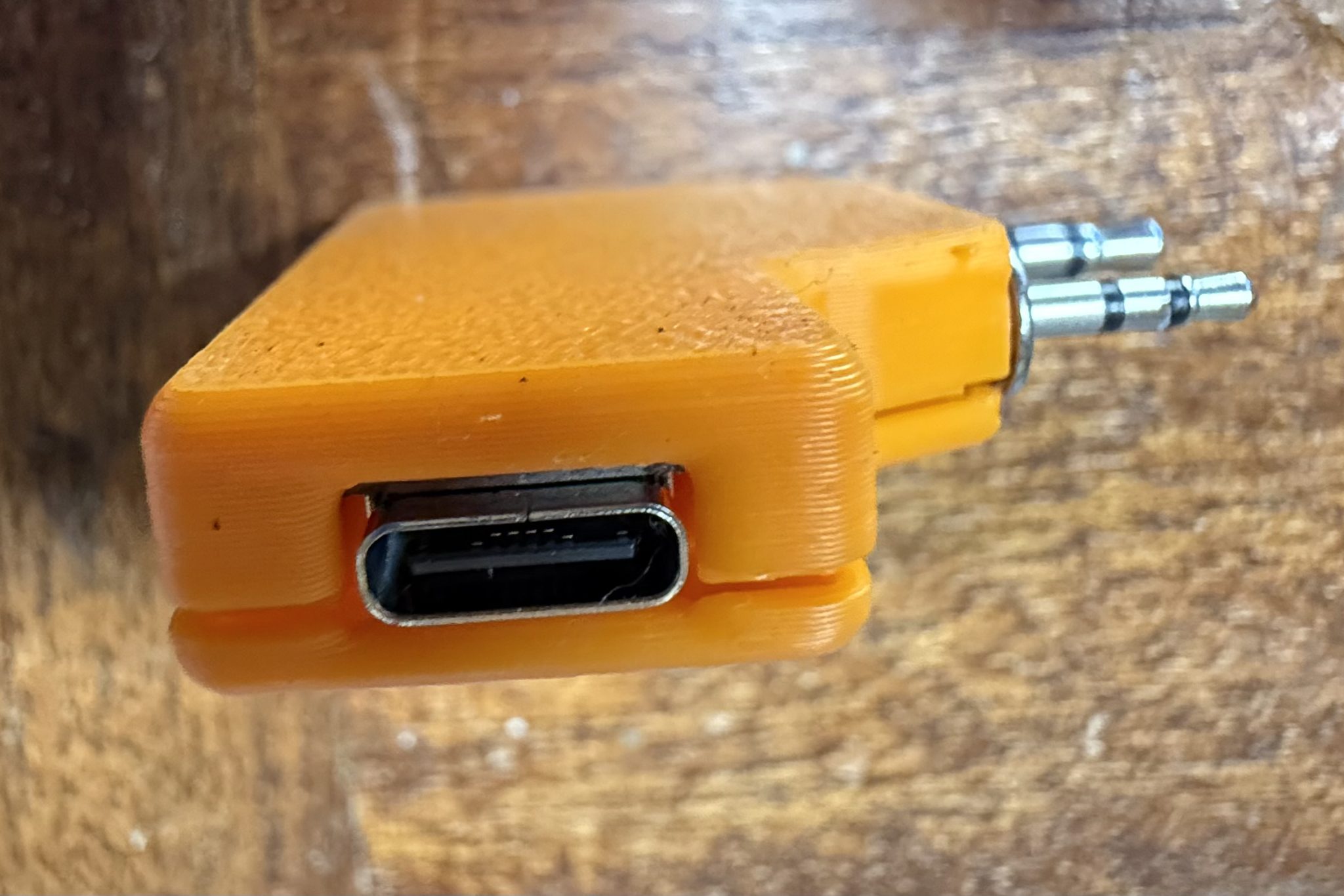
Once the print was complete I fitted the AIOC board and snapped it together ready for testing.
Fitting the AIOC into the 3D printed case.AIOC case with 2 x TRS connectors in place.AIOC case USB-C view
Now that the AIOC was production ready I moved on to getting the latest version of AllStarLink onto my RaspberryPi 4 that I had taken out of my RadioBerry based shortwave receiver that I am going to upgrade to a Hermes Lite 2 in a later project. The RaspberryPi 4 is perfect for AllStarLink 3, a 64bit app and operating system.
Using the RaspberryPi Imager I pulled the image down onto an SD card and slipped it into my Pi4. ( Instructions on how to do this are on the AllStarLink website here )
Booting the Pi4 for the first time I found that it went through a number of reboot and configuration cycles before it was ready for use.
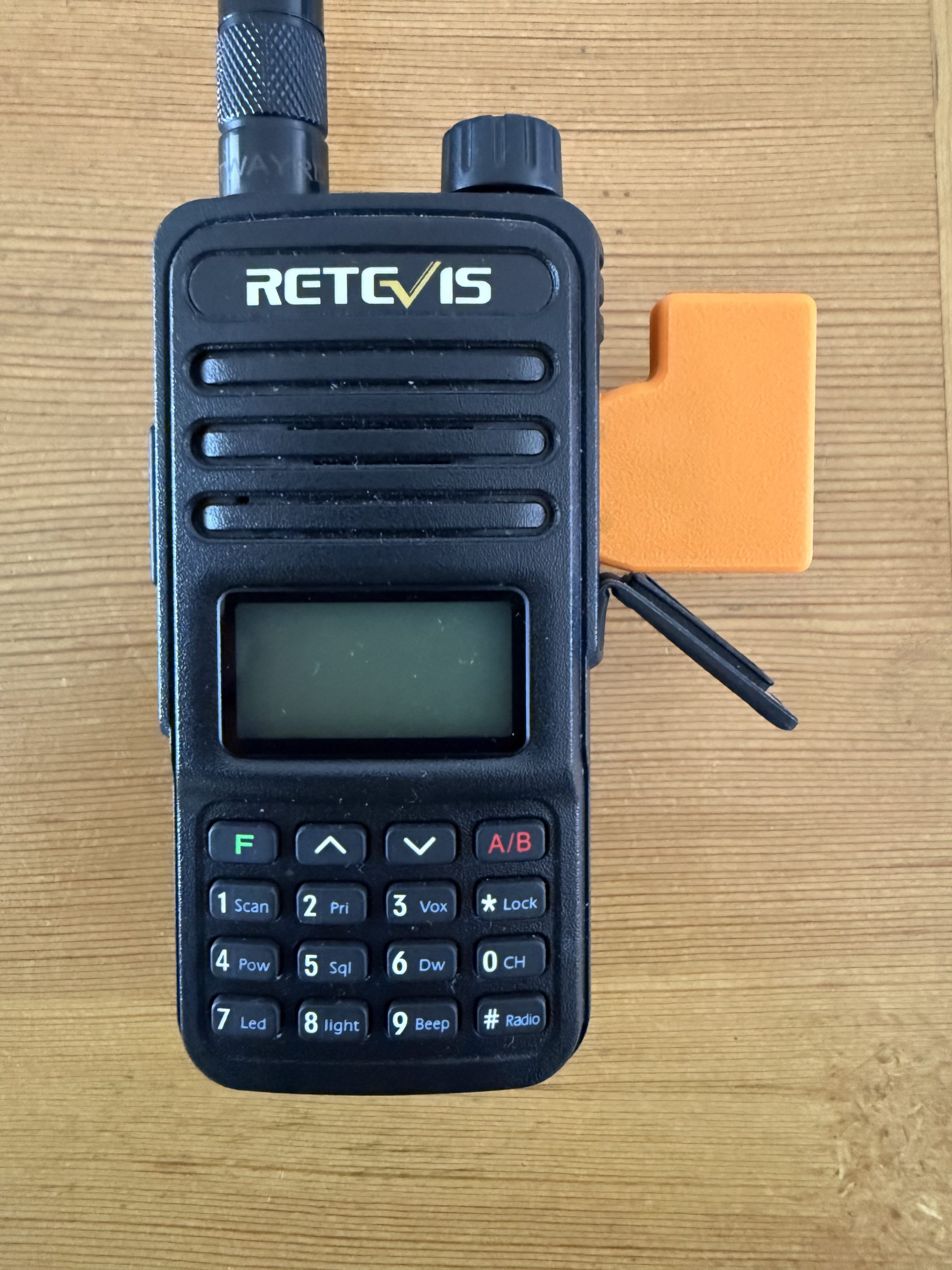
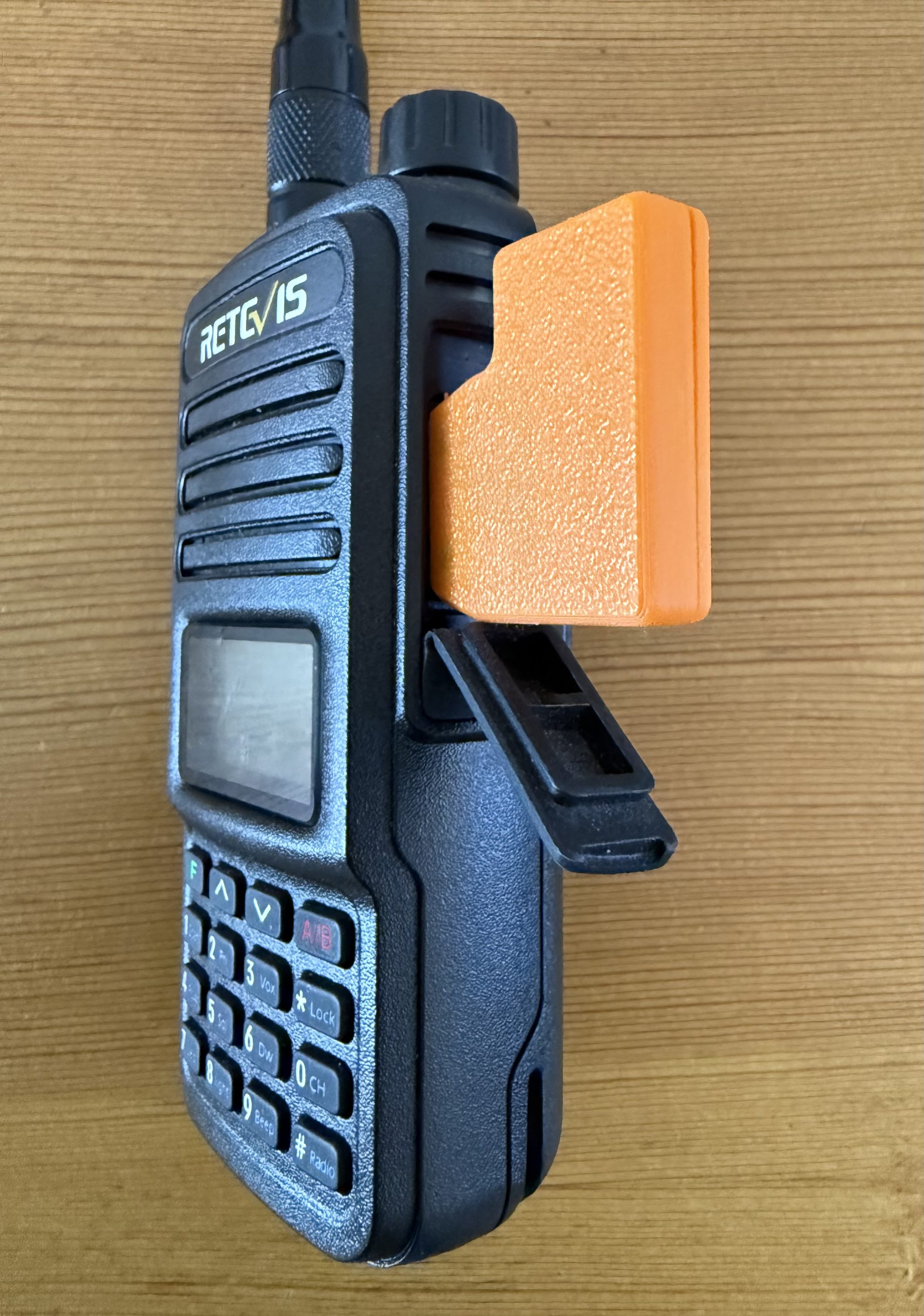
AIOC connected to the Retevis RT85.AIOC connected to the Retevis RT85.
Once ready I went through all the normal configuration of the Pi4 namely, static IP assignment, timezone config, security, port forwarding etc etc.
Having configured an AllStarLink node for myself and only just a few days ago for another HAM I was pretty familiar with the setup. Wanting to make sure there were no “gotcha’s” I also watched a couple of KM9G’s videos on Youtube to make sure I wasn’t missing anything.
Using the asl-menu command line app as user root I set about configuring Asterisk to work with the AIOC board. Much to my frustration I could not get Asterisk to recognise the AIOC board as an available sound device. I checked and double checked all the settings ensuring that I had selected “AIOC” in the available devices menu but found that Asterisk constantly errored saying it could not find the selected audio device. This went on for a whole day without success and so, I decided to put it to one side and come back to it later, a method I found that often worked.
A couple of days later I revisited the problem and had decided to take a different approach. Rather than continue going through the asl-menu app I decided to drop down to a lower level and go through the asterisk config files in the /etc/asterisk directory.
It wasn’t long before I found a file called res_usbradio.conf. Inside this file was the config for the AIOC board however, it was all commented out which meant it was disabled.
I’m guessing here but, I imagine this is what should get enabled when selecting AIOC in the available devices menu in the asl-menu command line app but, for some reason it doesn’t happen.
[general]
;usb_devices = 1209:7388    ;comma delimited list of usb
                            ;descriptors to allow.
                            ;format vvvv:pppp in hexadecimal
                            ;vvvv=vendor id, pppp=product id
                            ;
                            ;1209:7388 = AIOC (all in one cable)
Above is the disabled configuration which is easily edited to enable the AIOC device as shown below.
[general]
usb_devices = 1209:7388    ;comma delimited list of usb
                            ;descriptors to allow.
                            ;format vvvv:pppp in hexadecimal
                            ;vvvv=vendor id, pppp=product id
                            ;
                            1209:7388 = AIOC (all in one cable)
Once the updated file had been saved and I restarted Asterisk using systemctl the AIOC burst into life and Asterisk recognised it immediately. The Retevis RT85 switched between TX and RX and I was ready to check out the audio.
Setting the volume levels for both RX and TX via the command line tuning app I connected the node to my already existing node. Sure enough the two nodes connected without error and I was able to send and receive audio between them via the AllStarLink net.
Connecting the new node to the parrot I checked the audio levels to ensure it sounded ok and then connected it to the Matrix node where I had a brief chat with Ben, M8TKK.
All that is left to do now is to 3D print a case for the Pi4 so that it isn’t left naked and at risk of being shorted out on conductive surfaces and it’ll be ready for service.
I also plan to build another AllStarLink node using a 4m band handheld and another AIOC board and then will apply for MB7Ixx callsigns for the two new nodes. This will hopefully help to bring some life to the 2m/4m bands locally and introduce HAM’s both to the weekly Matrix Net and HUBNet/FreeStar via AllStarLink.
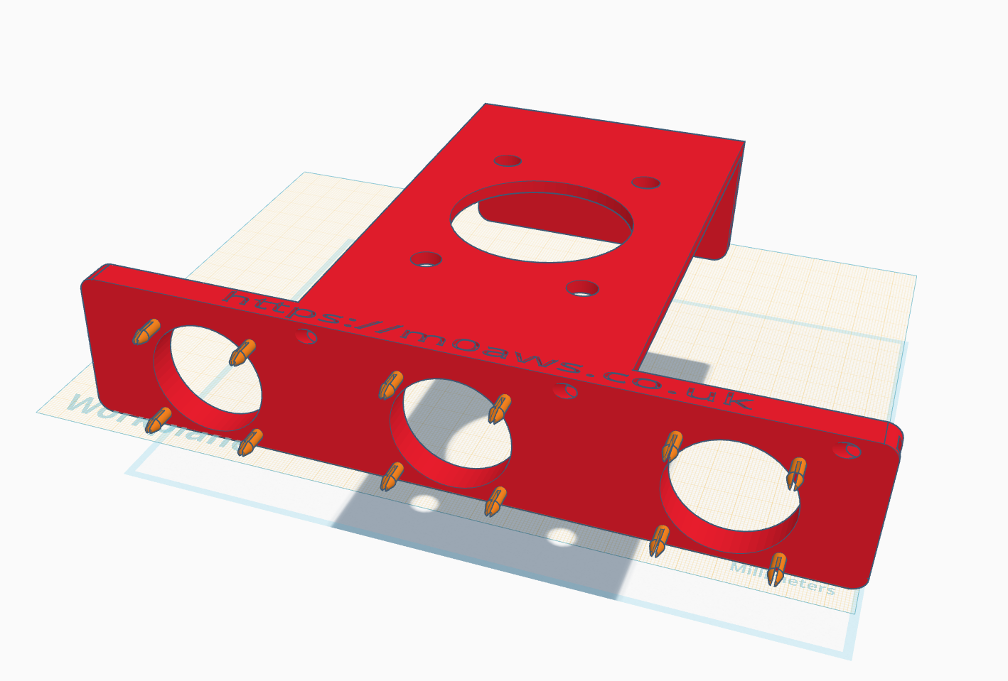
Having printed this for Steve, M0XVT and myself we’ve thoroughly tested it and found that it greatly reduces the temperature of the amp during operation.
I’ve now decided to make the .STL file available for download so that those who have their own 3D printer can print their own cooler for the amp.
The 40x40x10mm 12v fans that fit onto the mounts on the cooler module can be obtained from Amazon. (Note: Originally they came in packs of 4)
Designing the Xiegu XPA125b cooling system using tinkerCAD.Xiegu XPA125b Cooler with Hermes Lite 2 cradle – side view
I’m happy to print this for people who don’t have a 3D printer of their own, please contact me via email for a price.
For those who have their own 3D printer, the .STL file is available below for download.
Please note that I am releasing this STL file into the public domain for non-commercial, personal use only.
With the multitude of remote controlled smart plugs available today I’ve now got the ability to switch the station on remotely however, there’s been one issue that has plagued me until now and that’s the Xiegu amp doesn’t come on when power is applied to it, you have to press the power button on the front of the amp before it will fire up.
This of course stops me from being able to fully use the station remotely as there’s no one there to press the power button on the amp, until now.
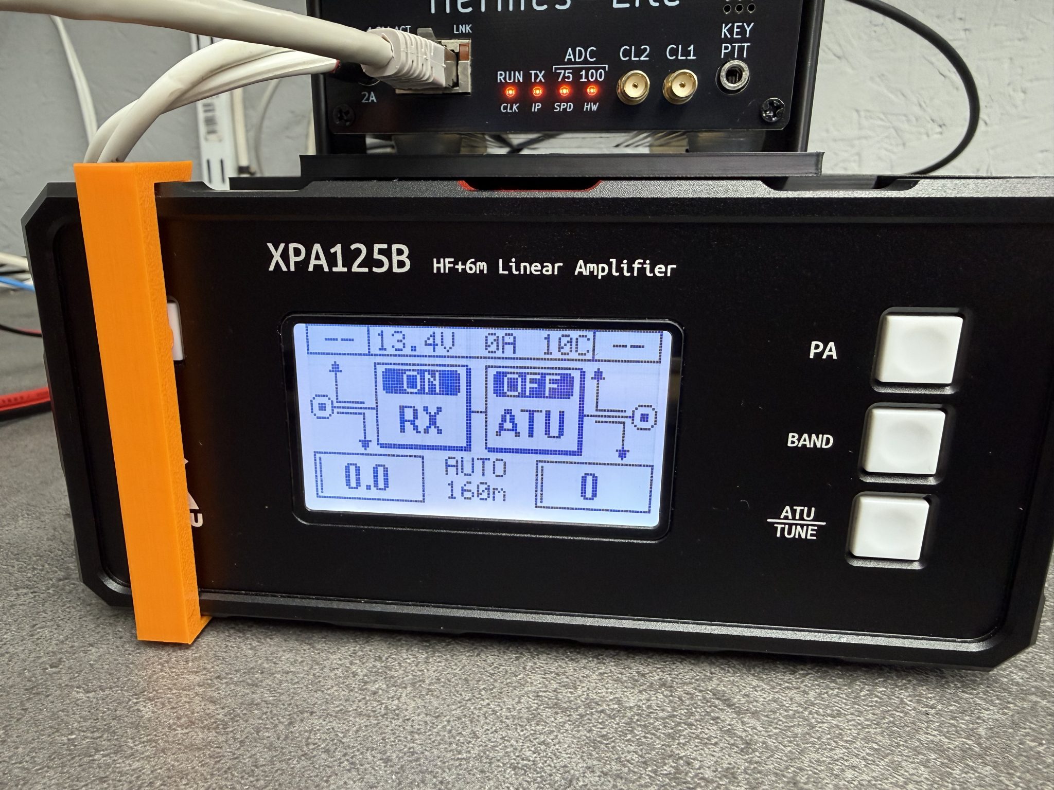
Chatting with Steve, M0XVT he discovered that if the power button is held pressed all the time the amp will come on when power is applied. This then gave me the idea of designing a button press device that I could 3D print and clip onto the front of the amp so that the button is always pressed.
M0AWS Xiegu XPA125B Clip on Power Button Press
The Xiegu amp has a very nice flange around the front edge of the amp case that lends itself nicely to clip on a simple button press device as shown above in my 3D design software.
The button press is designed so that the top is put on first and then the bottom is just snapped into place with a gentle push. This makes it easy to get on and off without marking the amplifier.
M0AWS Xiegu XPA125B Clip on Power Button Press
In just a few minutes I had the button press design uploaded to my Bambu Lab A1 Combo 3D printer and in no time at all the button press was ready for use.
As you can see in the photo above it fits snugly to the front of the amp gently holding the power button in so that the amp comes on when power is applied. Simple but, effective.
I’m sure I’m not the first person to have this problem and so, I’ve made the .STL 3D print file available for download below.
I’ve recently been trying out the FreeDV RADEv1 digital voice mode on the HF bands with great success. The audio quality is astounding when compared to the normal analog SSB mode. Using only 20w I’ve been surprised how successful I’ve been talking to stations in the UK and Europe as can be seen in my FreeDV Log.
FreeDV has been around for quite a few years with development being funded by an ARDC grant and financial sponsorship from the Software Freedom Conservancy.
“FreeDV is a suite of digital voice modes for HF radio. Our flagship mode is the Radio Autoencoder (RADE). You can run RADE using a free GUI application for Windows, Linux and macOS that allows any SSB radio to be used for high quality digital voice.“
And the most important part:
“All software is open source, released under the (a) GNU Lesser Public License version 2.1 (GUI and legacy FreeDV modes) and two-clause BSD license (RADE).“
FreeDV running under KDE-Plasma on Kubuntu PC
Looking at the digital voice (DV) community in the HAM Radio world, it’s stuffed full with proprietary DV modes from small software houses and black box transceiver manufacturers with no real OpenSource alternatives, until now.
Installing FreeDV is pretty simple regardless of which operating system (O/S) you use. Being a Linux user I grabbed the AppImage from the website and set about reading up on how it works and how it is configured.
I decided to take the two sound card approach since I have 2 USB sound cards connected to my shack Kubuntu Linux PC.
Configuring the audio routing isn’t straight forward as both the receive and transmit audio to/from the radio needs to be routed via the FreeDV app. To make this even more complicated I am using my Hermes Lite 2 SDR transceiver and PiHPSDR software, a complete OpenSource/OpenHardware Amateur Radio Station.
M0AWS FreeDV and PiHPSDR Audio Routing Diagram
Trying to clearly describe the audio routing using words alone would be impossible and very confusing so, I put together the diagram above.
Using two USB sound cards I’ve configured the system such that USB Sound Card 1 (an old Griffin iMic USB sound device) handles just the audio from/to the headphones and microphone. All the audio at this point in the system is analogue.
The second USB sound card, a cheap Plug and Play (PNP) USB audio device from Amazon, handles all the digitised signals from/to FreeDV and PiHPSDR.
Taking this 2 sound card approach keeps confusion to a minimum and separates the analogue and digital components of the audio routing.
So, how does this translate to the FreeDV and PiHPSDR audio settings?
Transmit Audio Chain
FreeDV Transmit Audio Settings
Starting at the beginning of the transmit audio chain, let’s look at the transmit audio settings in FreeDV.
Looking at the FreeDV Transmit audio settings screenshot below we can see that the Input From Microphone to Computer device is set to:
This is the digitised audio output from FreeDV (via USB Sound Card 2) to PiHPSDR and is used as the transmit audio that is sent to the Hermes Lite 2 transceiver.
FreeDV Transmit Audio Settings
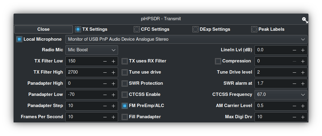
PiHPSDR Transmit Audio Setting
To complete the transmit audio path we next need to look at the PiHPSDR transmit audio setting.
PiHPSDR Transmit Audio Settings
As can be seen in the screenshot above, the Local Microphone device in PiHPSDR is set to the Monitor of USB PnP Audio Device Analogue Stereo.
This effectively routes the digitised output audio from FreeDV (Output From Computer to Radio device) to the Input audio of PiHPSDR.
The reason for using the Monitor audio feed is because FreeDV does not recognise the Mic Input in PiHPSDR as a valid output device for FreeDV to use, hence we just need to monitor the FreeDV output device and use it as our input audio device in PiHPSDR.
This completes the transmit audio chain.
Receive Audio Chain
PiHPSDR Receive Audio Setting
Starting at the beginning of the receive audio chain we first look at the PiHPSDR receive audio setting.
PiHPSDR Receive Audio Setting
In the screenshot above we can see that the receive audio output from PiHPSDR is set to USB PnP Audio Device Analogue Stereo (USB Sound Card2). This is the DX station’s digitised audio as received by the Hermes Lite 2.
FreeDV Receive Audio Settings
Next let’s look at the receive audio setting in FreeDV.
FreeDV Receive Audio Settings
The Input To Computer from Radio device is set to the monitor of the USB PnP Audio Output Device:
This is the analogue audio output on the iMic USB Sound card (Sound Card 1) that routes the analogue audio to the headphones and completes the receive audio chain.
Summary
The audio routing required by FreeDV can appear very daunting when first attempting to configure it on the Linux platform but, hopefully the diagram and screenshots above will help in understanding the complete end-to-end audio chain that is required to make this mode work.
PiHPSDR can of course be replaced by your black box radio CODEC entries that will appear in the device lists shown above if you have your radio connected via USB. The config is basically the same but, just uses a different device instead of USB sound card 2 shown in the diagram above.
I hope this article is useful to those wanting to try FreeDV on the Linux platform and I look forward to hearing you on RADEv1.
For sometime I’ve been using PiHPSDR software to drive my Hermes Lite 2 (HL2) SDR transceiver. It’s a great piece of OpenSource software for SDR transceivers and has the best documentation that I have ever seen from an OpenSource project.
I must admit, I’ve had to make a few changes to get the software how I like it but, that’s the great thing about OpenSource software, you get the source code and can do what you like to it.
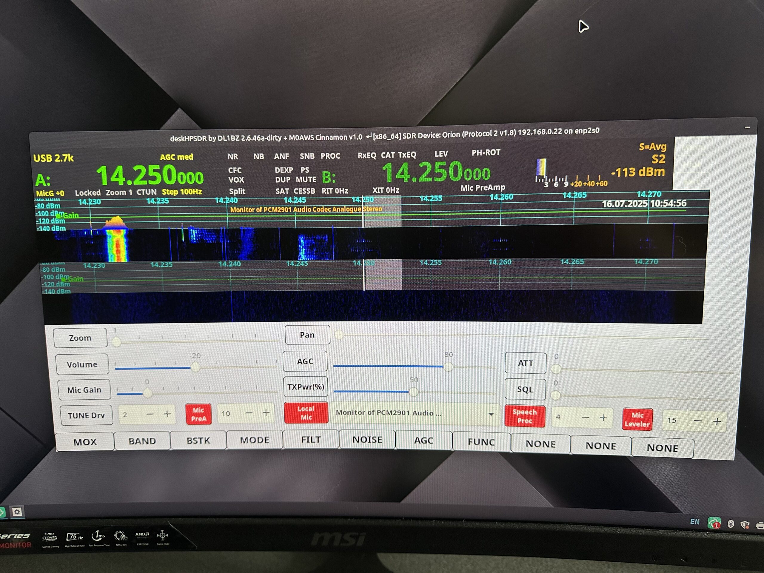
Following in this thread I recently decided to give DeskHPSDR a try. DeskHPSDR is a fork of the original PiHPSDR but, with some changes mainly aimed at larger display computers.
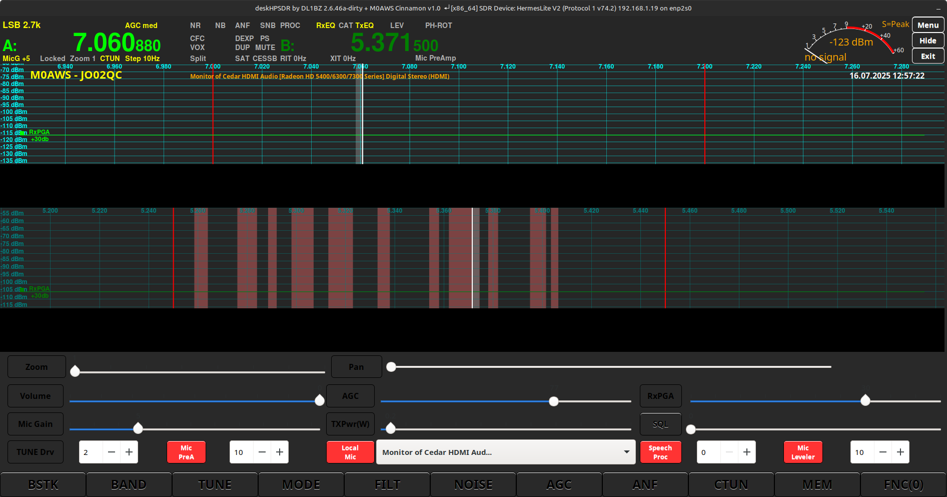
After compiling DeskHPSDR on my Kubuntu Linux PC in the radio shack, I found there were a few issues, mainly the colours were hard on the eyes and band/channel markers wrong/missing on a few of bands.
DeskHPSDR default colour scheme on Kubuntu 22.04LTS (KDE-Plasma)
I decided to dive in and take a look at the source code and try and sort out the colour issues as blue writing on dark buttons made them almost impossible to read under a KDE-Plasma desktop.
Delving through the appearance.c and css.c files I found that there were many changes required to get the end result I wanted. The biggest pain is that you have to recompile the source code after each change to see if the code change had worked, this results in many recompiles, a tedious task.
After spending many hours making changes I decided to email Heiko, DL1BZ who is the developer of DeskHPSDR. Over a number of emails we discussed getting the colour management code changed such that it was read in at start time from a separate css file rather than having to be compiled into the main program.
After a few emails back and forth, Heiko changed the code so that a separate CSS file could be read in at start up instead of the hard coded CSS in the C code files, this worked great and made it much easier to make colour changes without constant compilations of the code.
Next I needed to edit the bands.c file to change some of the band edge markers to show the UK band plan as, by default they are incorrect even though I have the region set to UK.
Editing the appearance.c file once more I was able to change the colour of the rather bright green panadapter signal display to a much more pleasing blue fading to red as the signal gets stronger.
One thing I really like about PiHPSDR was the channel markers on the 60m band. Anyone that uses the 60m band will know that the UK allocation is split into 11 different channels separated by spaces used by the primary user of the band. The channel markers make it just that bit easier to ensure you don’t stray out of the allocated channels however, this code had been removed from DeskHPSDR as Heiko didn’t consider it necessary.
Once again I pinged an email over to Heiko explaining how useful it is to UK HAMs and he very kindly put the code back into DeskHPSDR so that the 60m channels are once more clearly visible on the panadapter.
DeskHPSDR modified colour scheme on Kubuntu 22.04LTS (KDE-Plasma)
Feeling happy with the new colour configuration I decided to test it out on Linuxmint Cinnamon. Sadly the scheme that looked so nice under Kubuntu 22.04LTS didn’t look the same under Linuxmint and so I had to set about coming up with a version of the CSS file for this platform too.
After quite a few hours tinkering with CSS code I found it to be impossible to get the colour scheme on Linuxmint Cinnamon Edition identical to that I’d created under Kubuntu KDE-Plasma so, I settled for a look that was as close as possible.
DeskHPSDR on Linuxmint Cinnamon Edition with colour modifications.
Chatting with Steve, M0XVT we thought it would be a good idea to test it on his Kubuntu Linux and Linuxmint PCs. He is using a later version of Kubuntu than I am (24.04LTS) and so, it would be a good test to see if the colour scheme looked the same.
Sadly it turns out that for some bizarre reason the colours come out different in the later version of Kubuntu. This is a real nuisance as it means we’d need a separate colour scheme defining for each version of the O/S. Perhaps using CSS isn’t the best way to define a colour scheme in applications.
For some very strange reason the colours were also rendered differently on his Linuxmint PC even though he was using the same version of the O/S as I am.
DeskHPSDR running on Kubuntu 24.04LTS with colour scheme not rendering correctly
Another issue was found whilst testing on Steve’s computers which seems to be caused by the fact he uses an Anan 200D SDR.
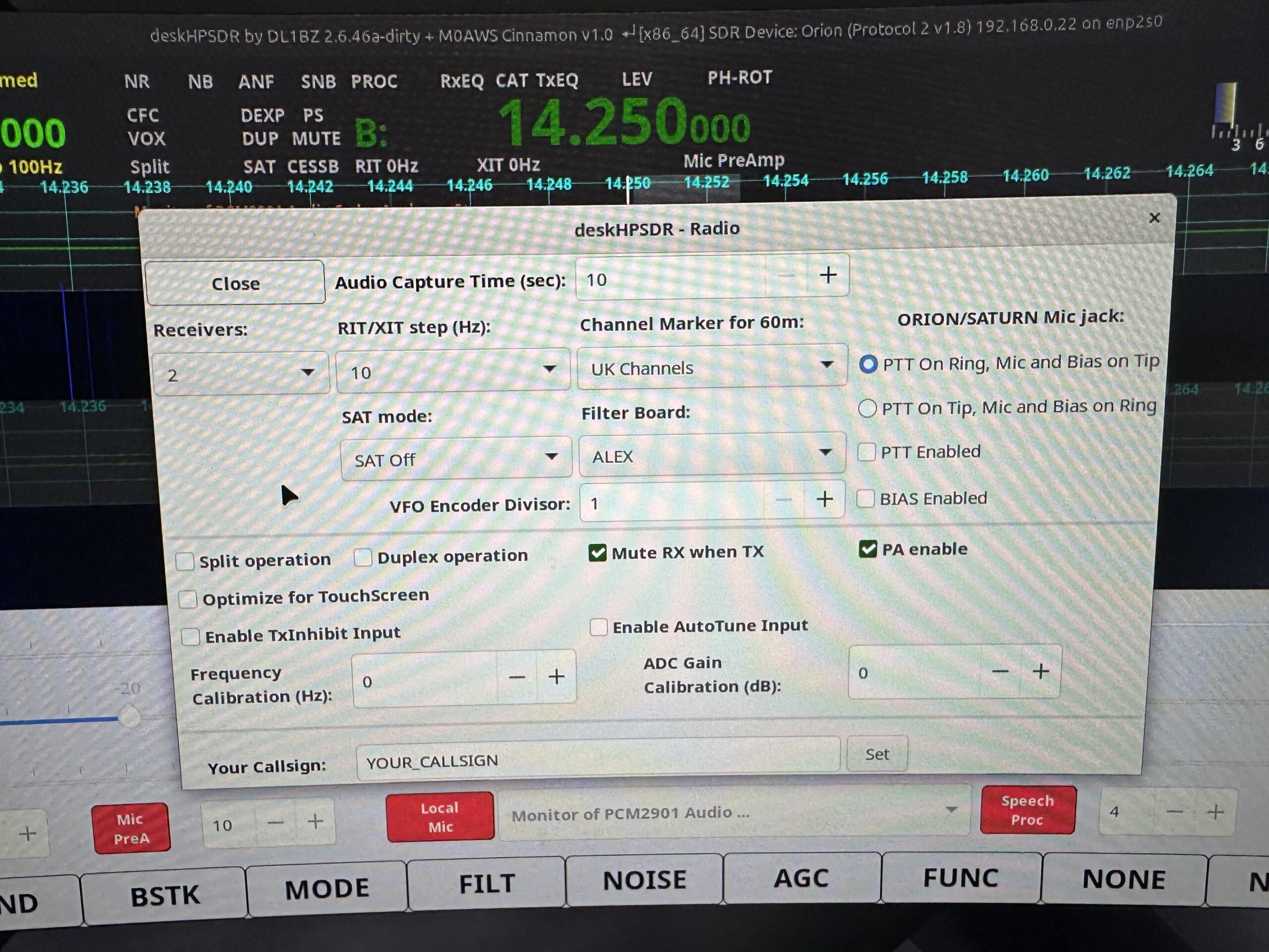
Looking at the documentation on github in theory DeskHPSDR should support the Anan range of SDR transceivers however, we found that it’s impossible to select the sample rate as the drop down selection list is completely missing from the Radio menu with the radio defaulting to its lowest sample rate of 48k resulting in not being able to see the full spectrum of frequency ranges on the bands.
DeskHPSDR Sample Rate drop down missing when using an Anan SDR
The other thing to note is that the Remote Server functionality has also been removed from the code by Heiko as he feels it’s not necessary. This may be a deal breaker for some and so they may choose not to use DeskHPSDR and to continue using PiHPSDR instead.
I will at some point make the O/S specific CSS files and source code available for download for those that want to use DeskHPSDR with my colour scheme changes.
I’m not sure at the moment whether I will continue using DeskHPSDR or go back to PiHPSDR, time will tell.
Over the last few weeks I’ve been working on my install-pihpsdr script to build a version of the DL1YCF PiHPSDR fork that will work with the Adalm Pluo, Pluto+ and LibreSDR transceivers.
Since I don’t own any of these devices, Steve M0XVT has loaned me his Adalm Pluto and LibreSDR devices to test with.
Initially neither of the devices would work with the PiHPSDR build that my script was creating. After some investigation I found this was due to the fact that the developer build script was only building the SOAPYSDR library, it wasn’t building the modules for each device type.
This was easily fixed by adding some extra code that would build the necessary SOAPYSDR modules so that the devices were discovered on the local LAN.
Since I had the devices to hand I took the opportunity to test the updated build script on a number of Linux Distro’s that I have to hand.
PiHPSDR running on Linuxmint 22.1 Cinnamon Edition using the LibreSDR transceiver
I tested the updated build script on Kubuntu 22.04LTS, Linuxmint 22.1 Cinnamon Edition and RaspberryPi 4/5 running the latest RaspberryPi OS 64bit version.
These all worked great with the transceivers and will now make a great platform for QO-100 stations that use either the Adalm Pluto, Pluto+ or LibreSDR devices.
Of course this build of PiHPSDR will also work with the Hermes Lite 2 and RadioBerry devices that I use most of the time in my own radio shack.
The updated PiHPSDR install script can be downloaded from my original blog article on the subject that is located here: https://m0aws.co.uk/?p=3686
The updated build script will most likely work on most Debian based Linux distro’s and build a working version of PiHPSDR. If you find a distro where you have problems please email me and let me know the details and I’ll happily look at the issue and try to resolve it.
Thanks to Steve for the loan of his precious SDR transceivers, I had a lot of fun with them!
More soon …
We use cookies to ensure that we give you the best experience on our website. If you continue to use this site we will assume that you are happy with it.