Bring your old handheld to life with an AIOC

I’m sure there are many radio amateurs around the world today who have an old handheld radio sat on the shelf that works perfectly but, has been replaced by a new, shiny, all singing, all dancing model that gets used on a daily basis. I for one have fallen into this trap with the recent purchase of a very nice Wouxun KG-UV9K full duplex 2m and 70cm handheld.

On my shelf there is a cheap Retevis RT85 that gave sterling service for a number of years and even today is ready to continue that service, if only I had a need?

Well now I do!

Currently I have an AllStarLink node running on a RaspberryPi 3b connected to a SHARI device that operates on the 70cm band. This node works great and gives me the ability to chat with people all over the world from my trusty handheld. It does of course also give me access to the weekly Matrix AllStarLink Net that happens on our Matrix node ( 642332 ) every Thursday evening at 20:00 UK time, a great way of bringing the Matrix HAM Radio community together regardless of propagation.

For some time I’ve been wanting to bring another AllStarLink node online so that I can have a connection to HUBNET/FreeNet whilst keeping my current node connected to the Matrix node for our regular daily chats. Since my new Wouxun handheld is a full duplex unit it makes sense to bring a new node up on the 2m band as I can then monitor both at the same time easily. I do have a spare SHARI node however, it’s a UHF only unit and I don’t want another node on the 70cm band. This is where the old Retevis RT85 comes in to play.

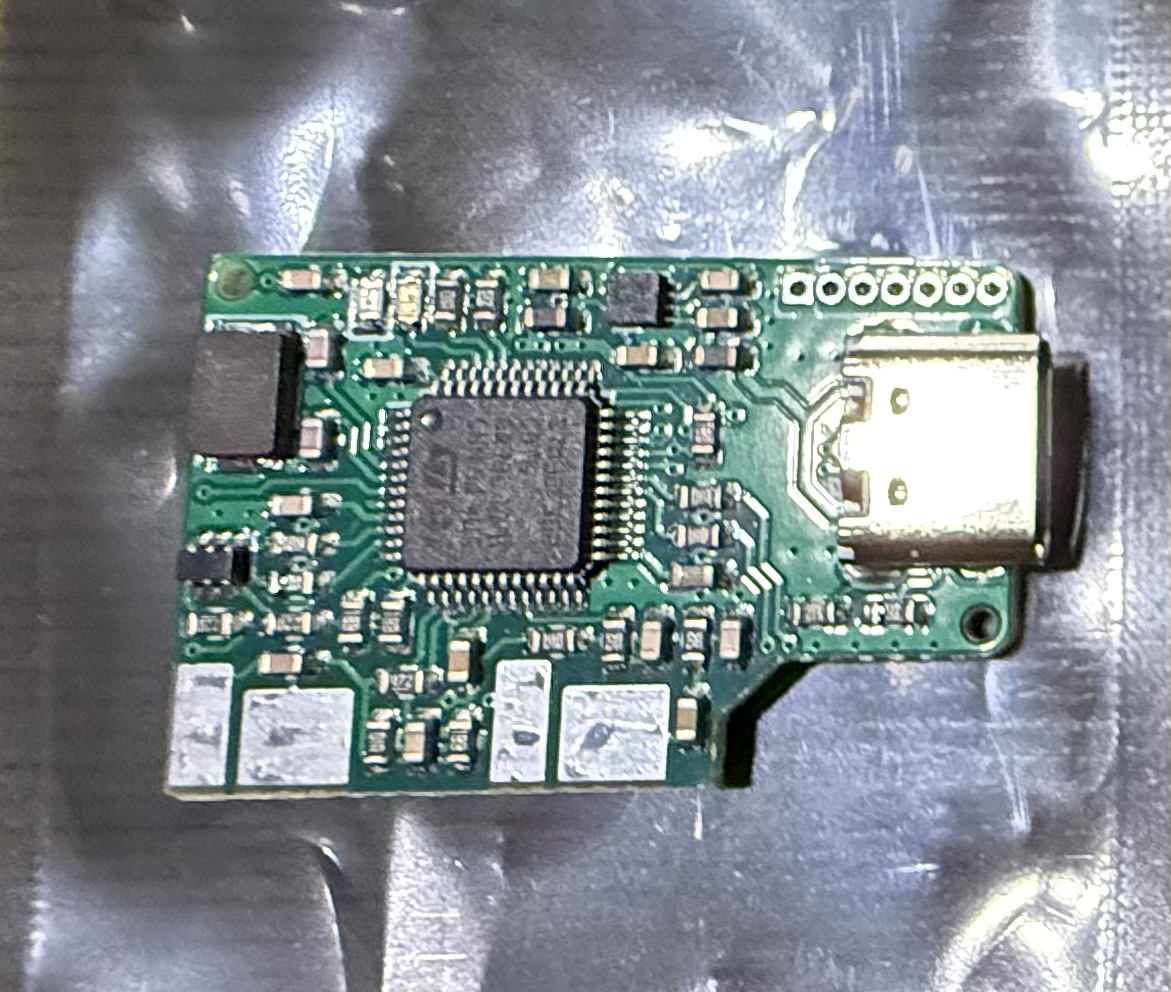
The All In One Cable ( AIOC ) board is a very neat little CM108 compatible sound card and serial interface that is sold by Steve, KM9G of YouTube fame ( Temporarily Offline ) that plugs into any handheld radio that has the now pretty much standard Kenwood ‘K’ type mic connector.

AIOC board from Steve, KM9G.

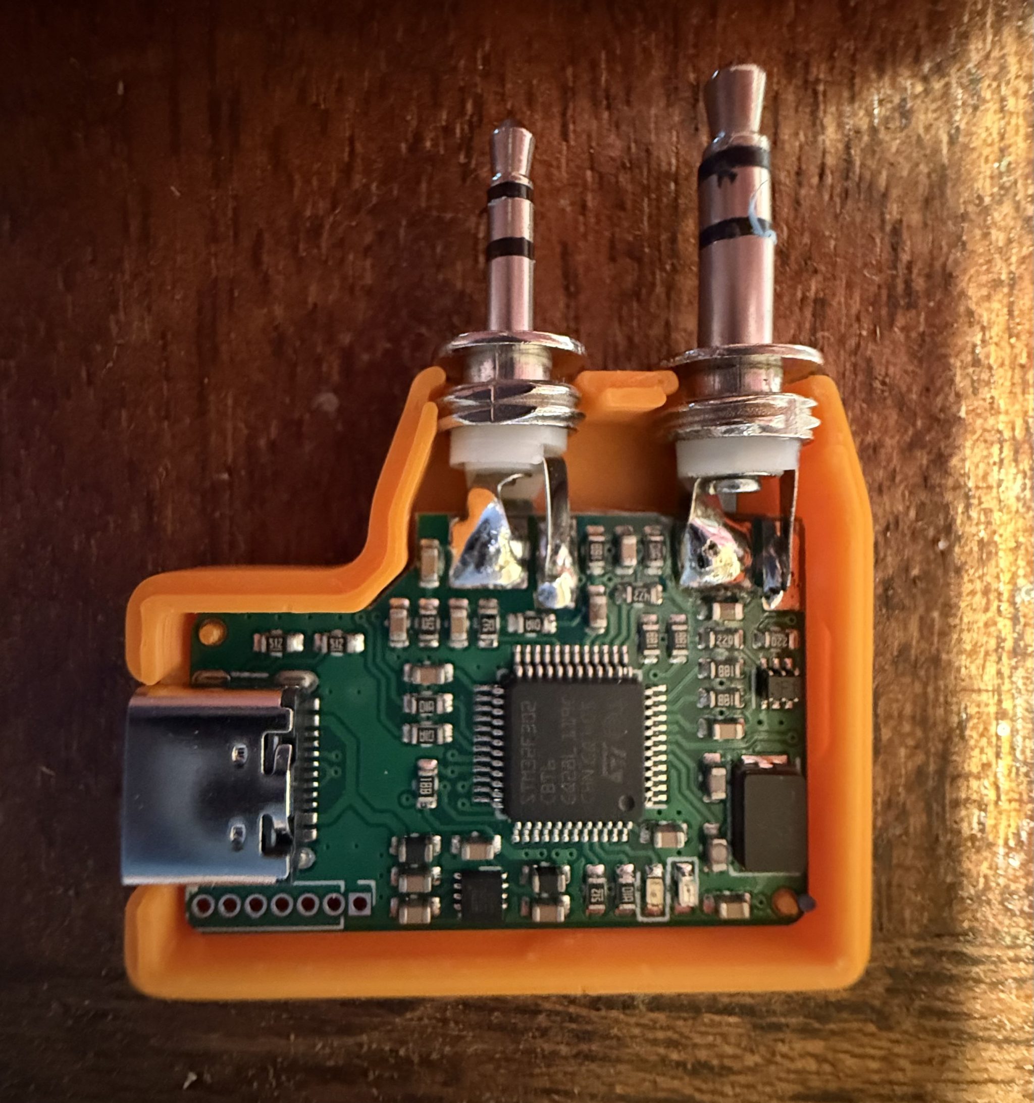
The AIOC board really is tiny but, beautifully put together. The four large solder pads on the top and more on the underside are positioned such that the TRS plug solder lugs line up perfectly for soldering. Attempting to do this by hand would be impossible as it’s critical that the spacing between the two connectors matches that of the spacing of the sockets on the radio.

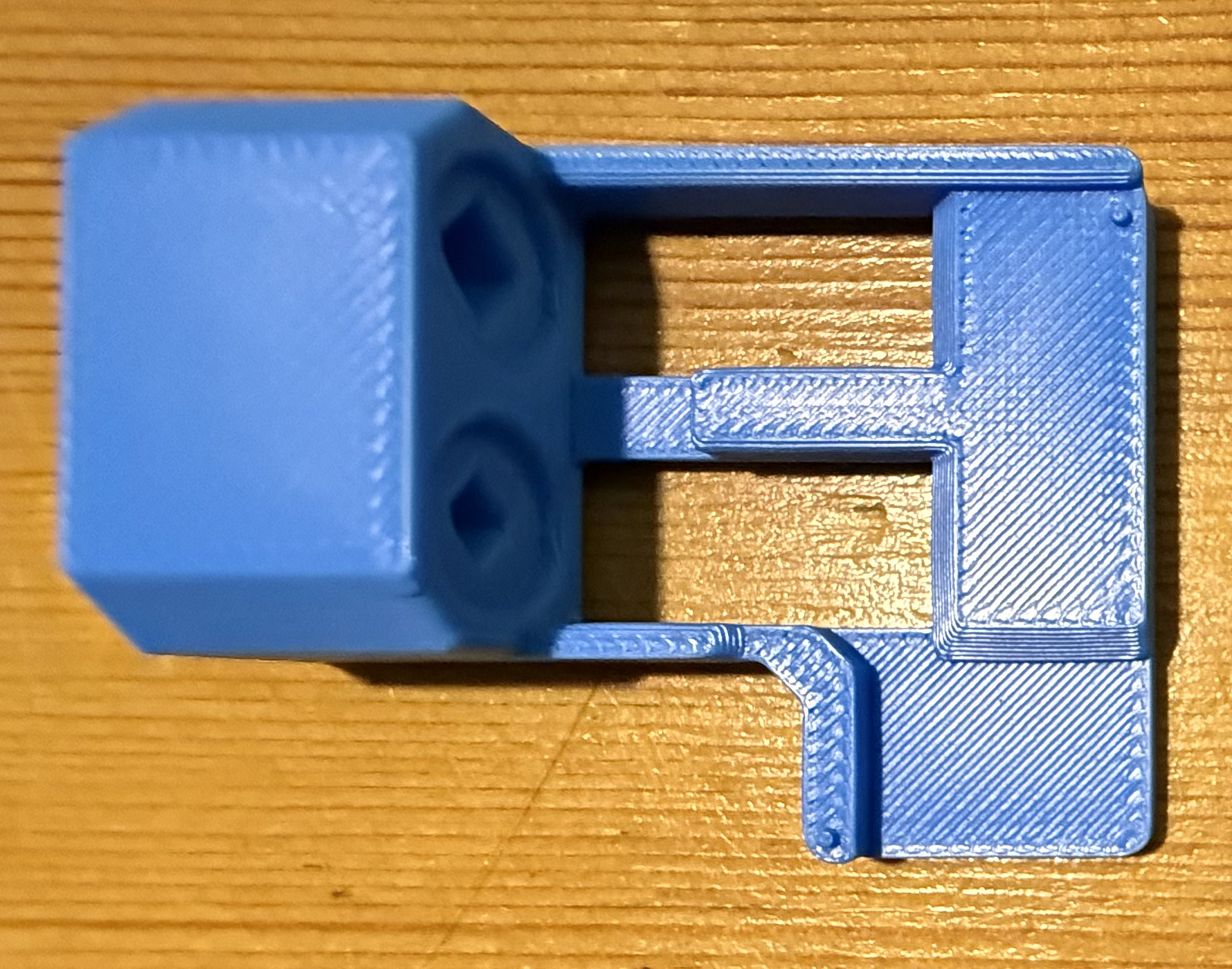
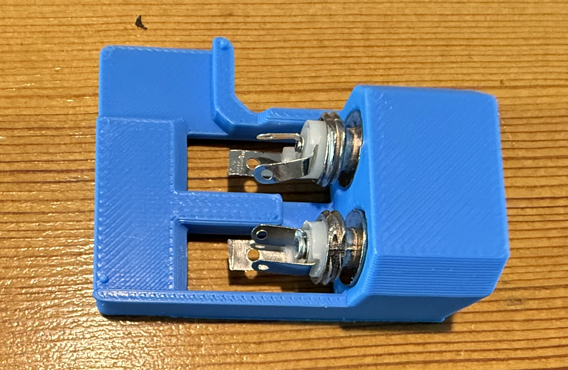
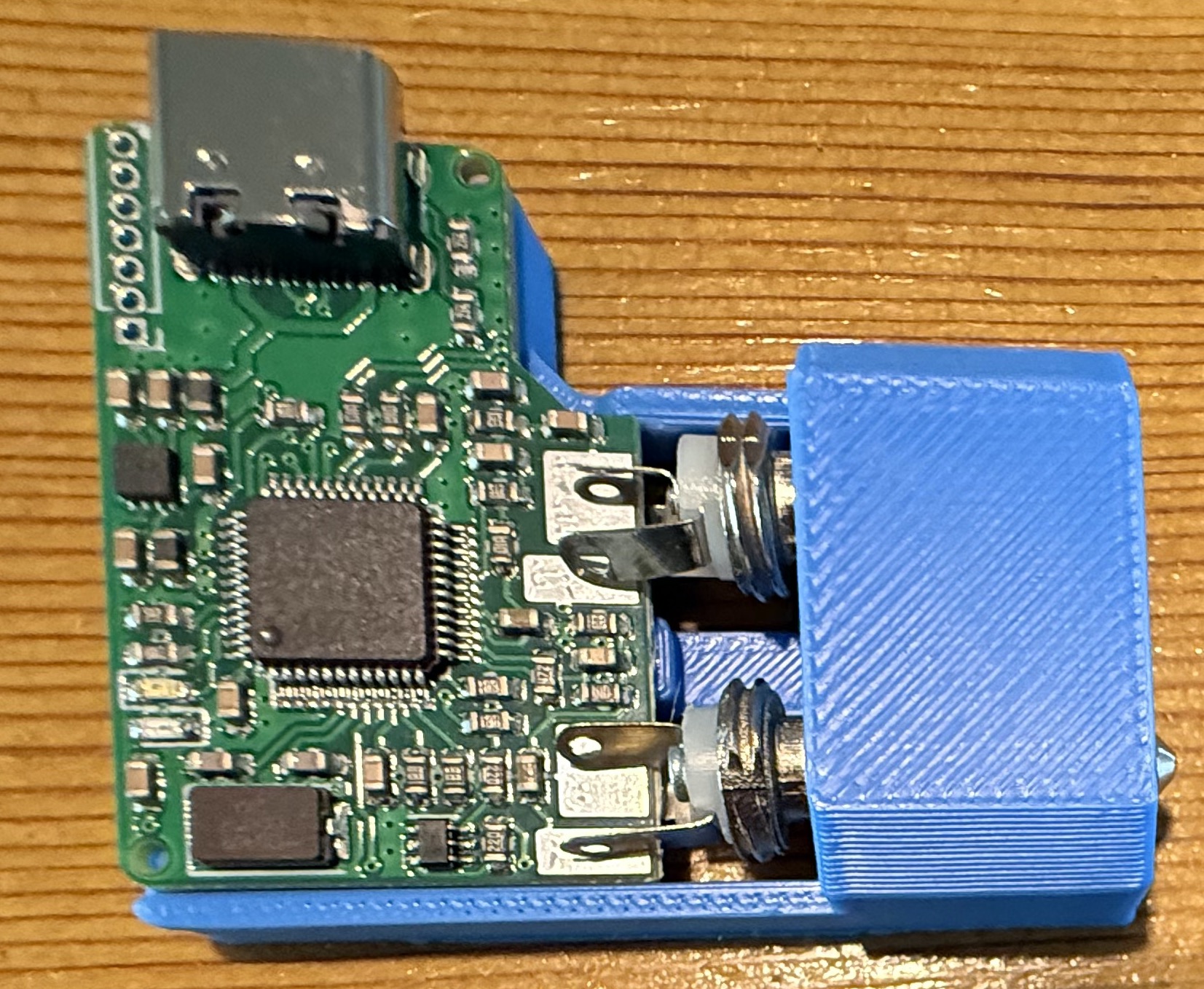
AIOC Solder Jig.
AIOC Solder Jig.

Searching online I found a very handy soldering jig on Github that enables you to hold both the TRS connectors and AIOC board in the perfect position for soldering.

Downloading the .STL file I quickly printed off a solder jig on my Bambu Lab A1 Combo 3D printer and fitted the components into place ready for soldering.

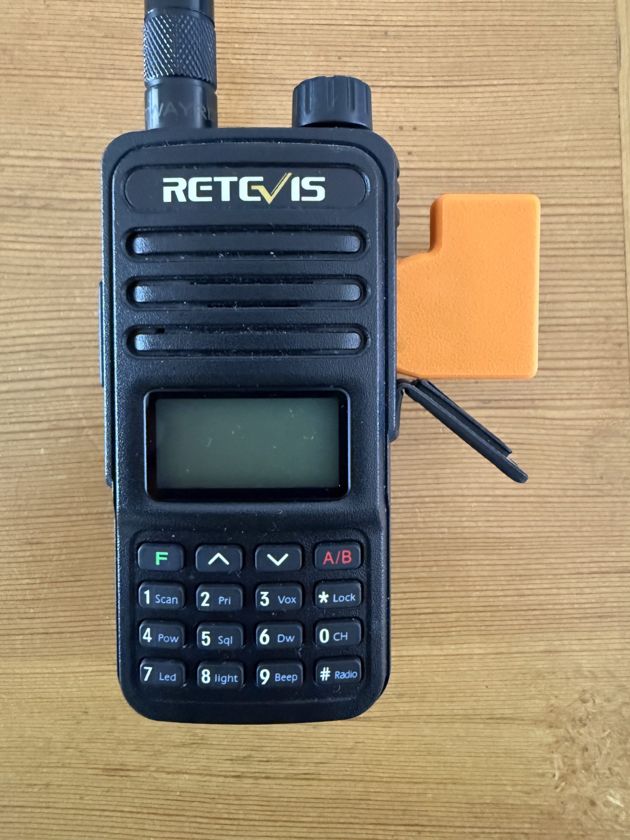
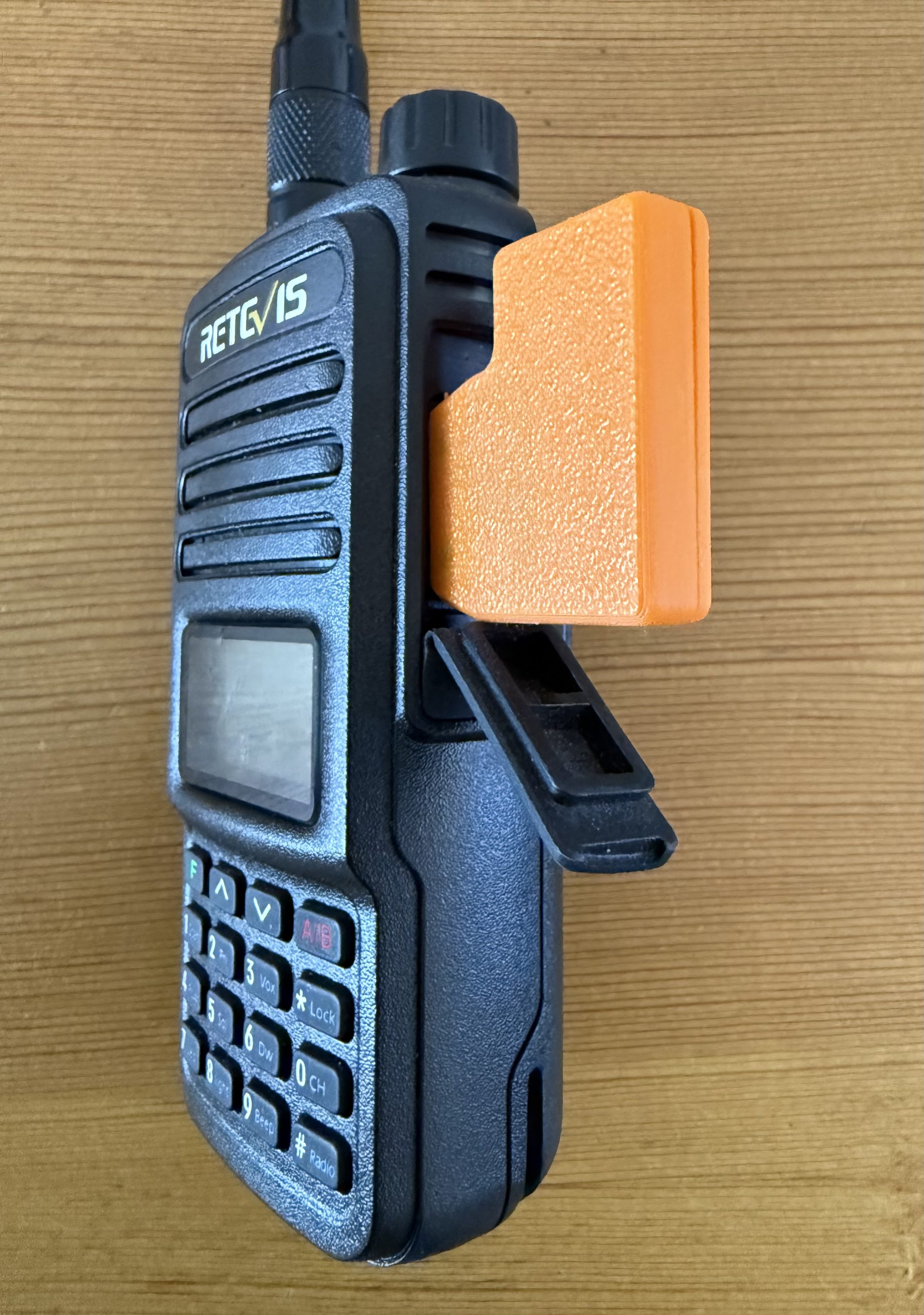
Everything fitted rather snugly into the jig and I soon had the board and connectors soldered together. Test fitting to my Retevis RT85 I found the TRS plugs lined up perfectly and it slid into the sockets with ease.

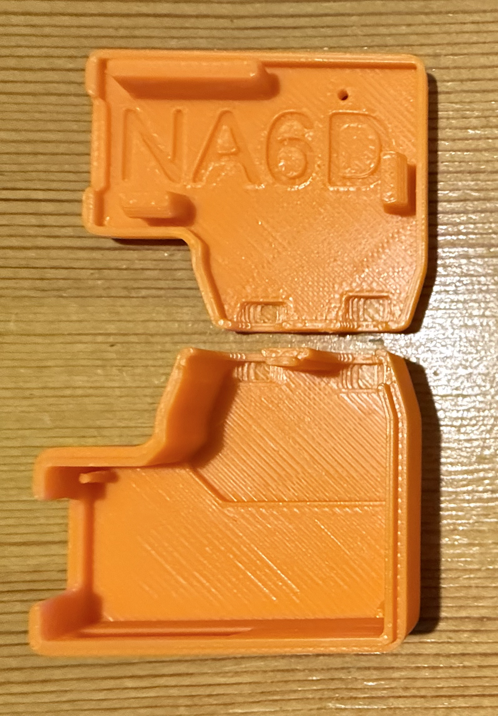
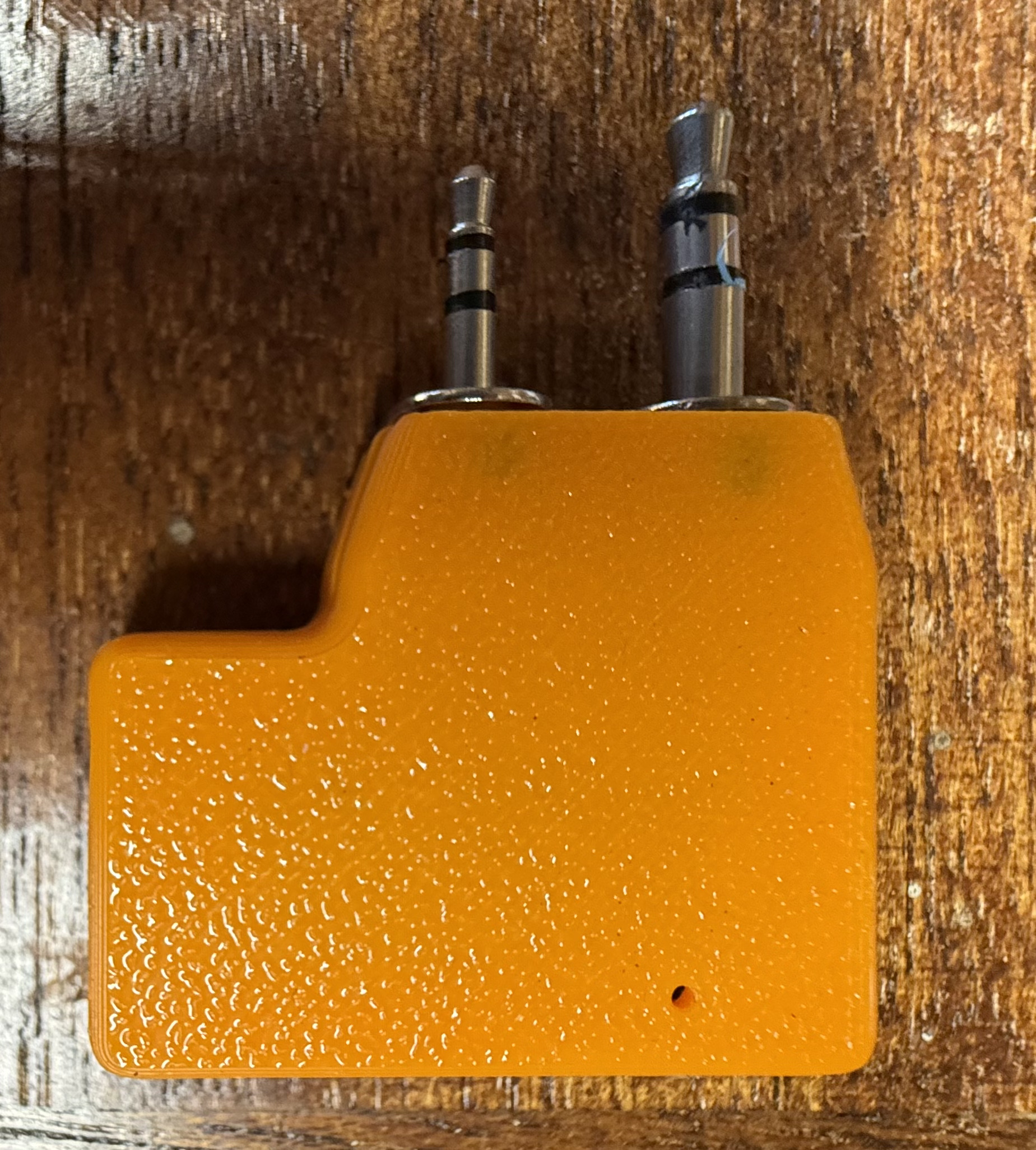
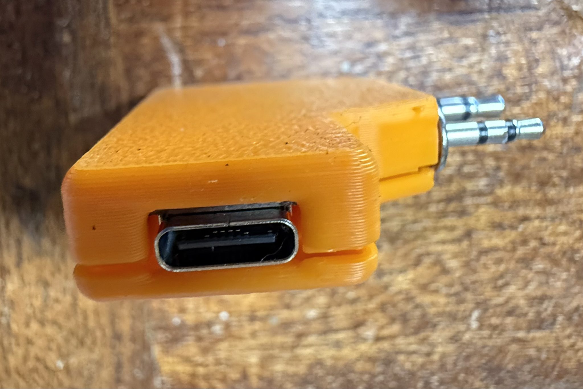
I then thought about designing a case for the AIOC board so that the bare circuit was nicely protected but, quickly searched online and found that NA6D has already designed a case and made the .STL available publicly for download on Printable.com. I quickly grabbed a copy of the file and punted it off to my 3D printer to get to work on.

3D print NA6D AIOC case.

Once the print was complete I fitted the AIOC board and snapped it together ready for testing.

Now that the AIOC was production ready I moved on to getting the latest version of AllStarLink onto my RaspberryPi 4 that I had taken out of my RadioBerry based shortwave receiver that I am going to upgrade to a Hermes Lite 2 in a later project. The RaspberryPi 4 is perfect for AllStarLink 3, a 64bit app and operating system.

Using the RaspberryPi Imager I pulled the image down onto an SD card and slipped it into my Pi4. ( Instructions on how to do this are on the AllStarLink website here )

Booting the Pi4 for the first time I found that it went through a number of reboot and configuration cycles before it was ready for use.

Once ready I went through all the normal configuration of the Pi4 namely, static IP assignment, timezone config, security, port forwarding etc etc.

Having configured an AllStarLink node for myself and only just a few days ago for another HAM I was pretty familiar with the setup. Wanting to make sure there were no “gotcha’s” I also watched a couple of KM9G’s videos on Youtube to make sure I wasn’t missing anything.

Using the asl-menu command line app as user root I set about configuring Asterisk to work with the AIOC board. Much to my frustration I could not get Asterisk to recognise the AIOC board as an available sound device. I checked and double checked all the settings ensuring that I had selected “AIOC” in the available devices menu but found that Asterisk constantly errored saying it could not find the selected audio device. This went on for a whole day without success and so, I decided to put it to one side and come back to it later, a method I found that often worked.

A couple of days later I revisited the problem and had decided to take a different approach. Rather than continue going through the asl-menu app I decided to drop down to a lower level and go through the asterisk config files in the /etc/asterisk directory.

It wasn’t long before I found a file called res_usbradio.conf. Inside this file was the config for the AIOC board however, it was all commented out which meant it was disabled.

I’m guessing here but, I imagine this is what should get enabled when selecting AIOC in the available devices menu in the asl-menu command line app but, for some reason it doesn’t happen.

[general]
;usb_devices = 1209:7388    ;comma delimited list of usb
                            ;descriptors to allow.
                            ;format vvvv:pppp in hexadecimal
                            ;vvvv=vendor id, pppp=product id
                            ;
                            ;1209:7388 = AIOC (all in one cable)

Above is the disabled configuration which is easily edited to enable the AIOC device as shown below.

[general]
usb_devices = 1209:7388    ;comma delimited list of usb
                            ;descriptors to allow.
                            ;format vvvv:pppp in hexadecimal
                            ;vvvv=vendor id, pppp=product id
                            ;
                            1209:7388 = AIOC (all in one cable)

Once the updated file had been saved and I restarted Asterisk using systemctl the AIOC burst into life and Asterisk recognised it immediately. The Retevis RT85 switched between TX and RX and I was ready to check out the audio.

Setting the volume levels for both RX and TX via the command line tuning app I connected the node to my already existing node. Sure enough the two nodes connected without error and I was able to send and receive audio between them via the AllStarLink net.

Connecting the new node to the parrot I checked the audio levels to ensure it sounded ok and then connected it to the Matrix node where I had a brief chat with Ben, M8TKK.

All that is left to do now is to 3D print a case for the Pi4 so that it isn’t left naked and at risk of being shorted out on conductive surfaces and it’ll be ready for service.

I also plan to build another AllStarLink node using a 4m band handheld and another AIOC board and then will apply for MB7Ixx callsigns for the two new nodes. This will hopefully help to bring some life to the 2m/4m bands locally and introduce HAM’s both to the weekly Matrix Net and HUBNet/FreeStar via AllStarLink.

More soon …

1946 Philips 170A-15 RadioBerry Receiver Project

Back in January 2025 I wrote an article about a little RadioBerry Project I’d started that was based around a very old Philips 170A-15 receiver from 1946.

The idea of the project was to build a nice shortwave receiver for the radio shack based around the RadioBerry HAT on a RaspberryPi 4 housed in a vintage receiver cabinet.

The project has taken longer than I imagined due to getting side-tracked by other projects that I already had ongoing.

1946 Philips 170A-15 Shortwave Receiver Internal View

With the original internals removed there’s plenty of room inside for the RadioBerry, RaspberryPi 4 and the small 15w audio amplifier. The audio is delivered via a pair of Celestion speakers that I had that were originally part of an old surround sound TV system.

Power distribution is achieved very simply using a multi-plug adapter that also has USB A connections in it. The whole thing is then powered via one 240v mains cable.

The screen fits over the original opening for the glass tuning display and is held in place by two mounting screws on the rear of the LCD panel.

I purchased some new speaker grill cloth from Amazon and remade the speaker grill front with cut outs for the speakers. It looks really tidy and matches the rest of the bakelite cabinet nicely.

1946 Philips 170A-15 Shortwave Receiver RadioBerry HAT on RaspberryPi 4

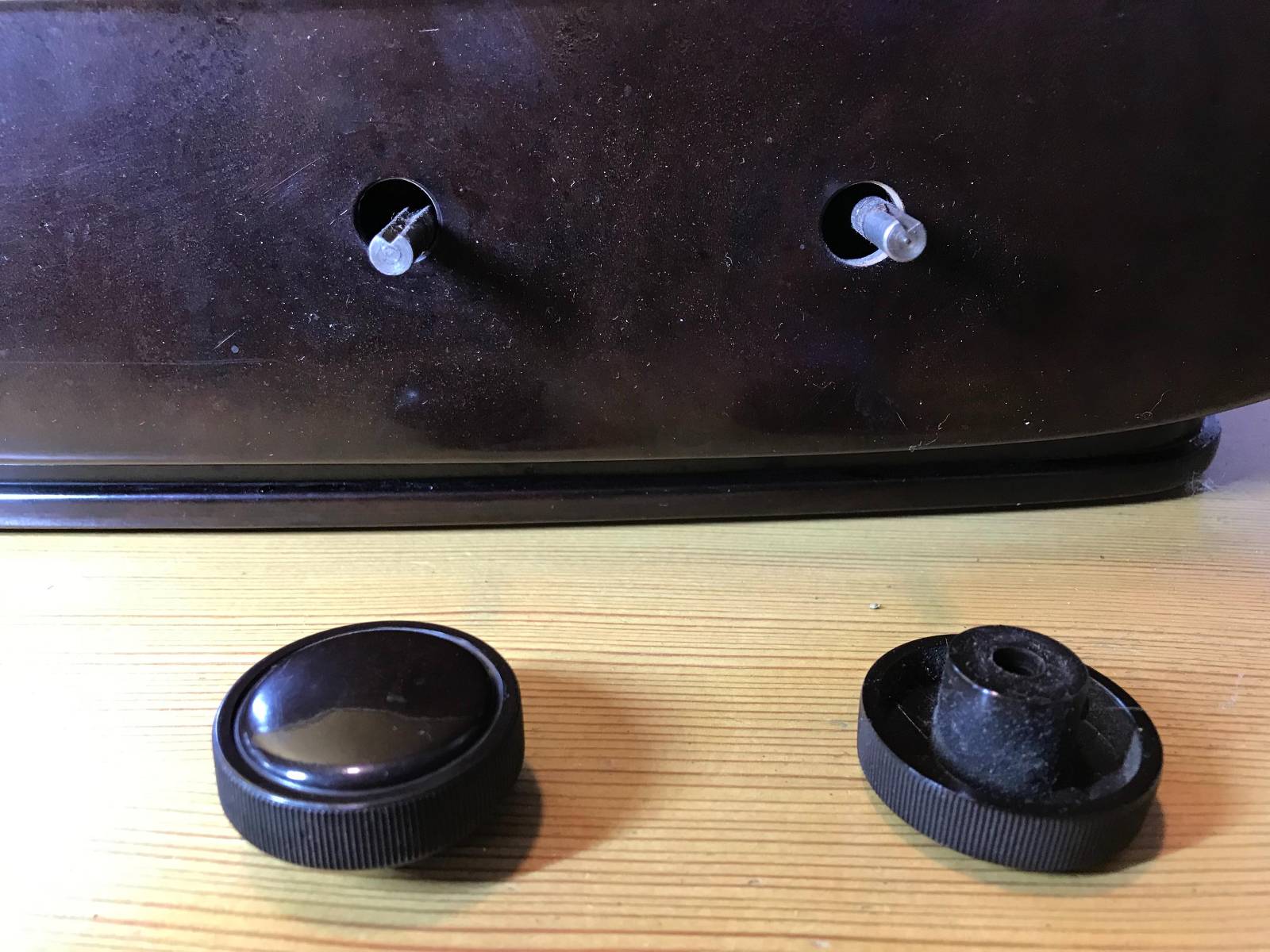
To finish the project off I need to purchase 3 rotary encoders so that I can have a VFO knob and two more knobs for other things (to be determined). The Volume control is already in place with the original knob fitted to it. It will be nice to complete the 4 knob line up.

1946 Philips 170A-15 Shortwave Receiver Rear Panel

I had to make a couple of fittings top and bottom to hold the original rear panel in place but, it worked out just fine and I only had to fit an SO239 antenna connector and ethernet RJ45 port so that it can be connected to my local LAN.

Receiving radio Caroline on 648Khz

The audio quality from the little RadioBerry and 15w amp is pretty good. With the speakers hidden nicely behind the refurbished speaker grill the project looks quite tidy!

It also makes a great receiver for the HAM bands with it’s coverage of 100Khz to 30Mhz.

The DL1YCF Enhanced fork of PiHPSDR works really well on the touchscreen and provides a modern control interface to the RadioBerry HAT.

Listening to the 20m HAM Band

I’ll drop a final article once I have purchased the 3 rotary encoders to fill the 3 remaining holes in the front of the cabinet.

More soon …

Updates to my install-pihpsdr.sh script

Over the last few weeks I’ve been working on my install-pihpsdr script to build a version of the DL1YCF PiHPSDR fork that will work with the Adalm Pluo, Pluto+ and LibreSDR transceivers.

Since I don’t own any of these devices, Steve M0XVT has loaned me his Adalm Pluto and LibreSDR devices to test with.

Initially neither of the devices would work with the PiHPSDR build that my script was creating. After some investigation I found this was due to the fact that the developer build script was only building the SOAPYSDR library, it wasn’t building the modules for each device type.

This was easily fixed by adding some extra code that would build the necessary SOAPYSDR modules so that the devices were discovered on the local LAN.

Since I had the devices to hand I took the opportunity to test the updated build script on a number of Linux Distro’s that I have to hand.

PiHPSDR running on Linuxmint 22.1 Cinnamon Edition using the LibreSDR transceiver

I tested the updated build script on Kubuntu 22.04LTS, Linuxmint 22.1 Cinnamon Edition and RaspberryPi 4/5 running the latest RaspberryPi OS 64bit version.

These all worked great with the transceivers and will now make a great platform for QO-100 stations that use either the Adalm Pluto, Pluto+ or LibreSDR devices.

Of course this build of PiHPSDR will also work with the Hermes Lite 2 and RadioBerry devices that I use most of the time in my own radio shack.

The updated PiHPSDR install script can be downloaded from my original blog article on the subject that is located here: https://m0aws.co.uk/?p=3686

The updated build script will most likely work on most Debian based Linux distro’s and build a working version of PiHPSDR. If you find a distro where you have problems please email me and let me know the details and I’ll happily look at the issue and try to resolve it.

Thanks to Steve for the loan of his precious SDR transceivers, I had a lot of fun with them!

More soon …

Breathing new life into a vintage receiver

Sometime back I purchased a RadioBerry HAT for my RaspberryPi 4 single board computer (SBC) to use as an experimental platform to test PiHPSDR software modifications and to test changes to the actual RadioBerry software. With these two projects completed I decided that the receiver on the RadioBerry was so good it would be a shame not to put it to good use.

RadioBerry HAT
RadioBerry HAT

For many decades I’ve been an avid Short Wave Listener (SWL) but, haven’t had a general coverage receiver for many years. The RadioBerry fills this gap in my radio lineup perfectly but, needs to be put into a suitable cabinet with speakers, display, control knobs and antenna connections.

Rather than just buy another bland square box I decided it would be nice to repurpose an old, vintage radio receiver from a bygone era and bring it into the 21st Century.

1950 Philips valve radio receiver
1946 Philips valve radio receiver

After much searching on the popular auction sites online I eventually found the perfect old receiver for the project, a vintage Philips 170A-15 valve receiver from 1946.

This lovely old Art Deco looking receiver is made from Bakelite which was an early type of plastic made from phenol-formaldehyde resin, obtained from coal tar and methanol.

The full specification for the receiver can be found on the Radio Museum Website.

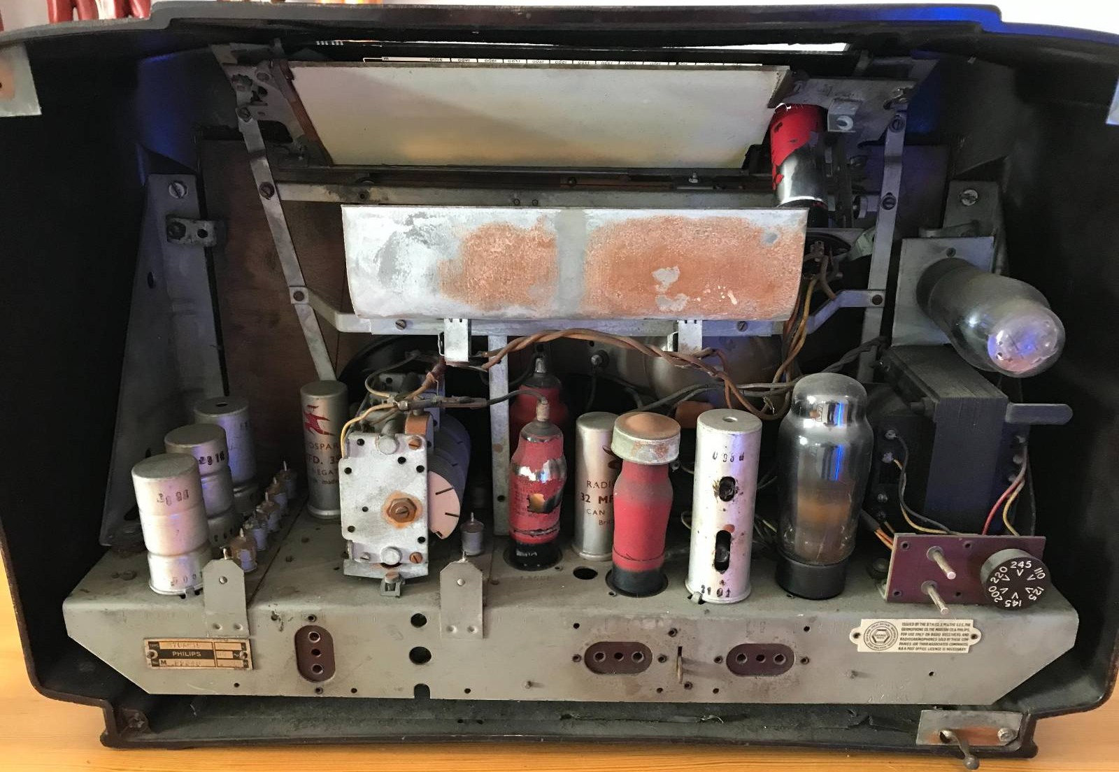
Sadly this is a non working example of this lovely old receiver and so I don’t feel so guilty stripping it out and replacing it’s internals with the RadioBerry.


Having the original serial number and Licence plate on the radio is nice, it also makes it easy to search for information about the old receiver.

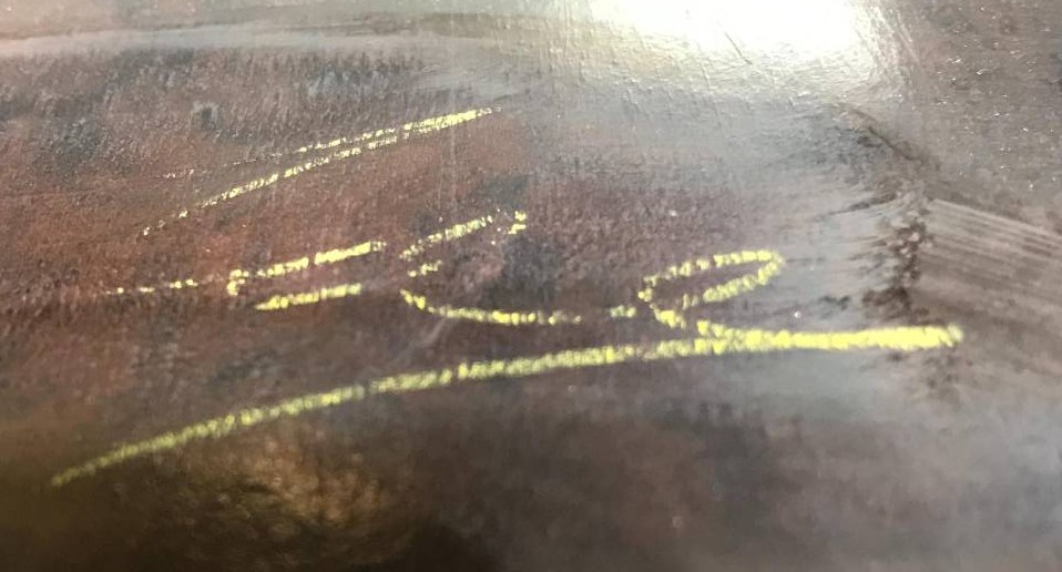
One nice thing I did discover during the disassembly of the receiver was the signature of the person that put the radio together during manufacture on the inside of the Bakelite cabinet.

1946 Philips receiver builder signature

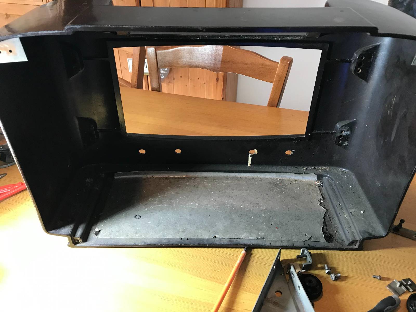
Getting the internals out of the cabinet was fun, so many little screws holding the old valve electronics and tuning display in place.

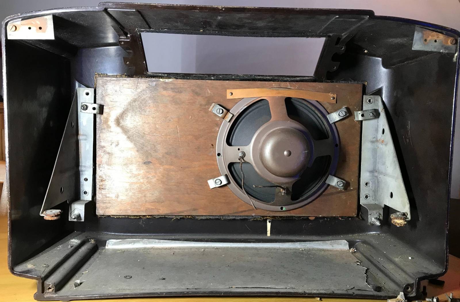
Once the electrical part of the radio was removed I gained access to the old speaker that was fitted to the front panel of the receiver. Unfortunately the speaker cone had a tear in it rendering it useless so I’ll need to get a new speaker(s) for the rebuild.

1946 Philips receiver speaker view

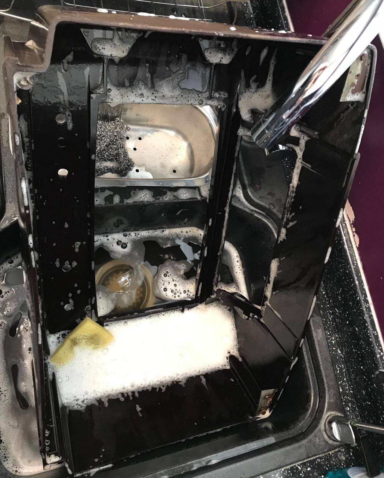
Once I got the speaker and fittings removed I set about cleaning the cabinet inside and out to remove the 79 years worth of dirt and grime that had collected within. The fascia of the receiver cabinet seems to have lost it’s shine and will need to be polished to get it back to it’s original beauty.

It took 5 lots of fresh water and washing up liquid to get the cabinet clean. The first three lots of water looked like mud in no time at all such was the state of the cabinet.

With the cabinet now cleaned and put to one side to dry thoroughly I have started to search for the best type of polish to use to put the sheen back onto it.

Once I’ve got the cabinet looking good again I’ll start fitting the new internals. I also need to find a source for a new piece of material to cover the speaker hole at the front of the cabinet as the original material is looking somewhat tired.

The old Philips Emblem from 1946 on the receiver case

More soon …

Using the DL1YCF version of PiHPSDR with the RadioBerry

(This information is also for the Hermes Lite 2, Adalm Pluto, Pluto+ and LibreSDR)

During my RadioBerry build I started out using the version of PiHPSDR that was created just for the RadioBerry. The problem with this is that it is hard coded for a very small screen making it hard to use on a big screen since the user cannot resize the window dynamically.

I decided to look for a forked version of the PiHPSDR software that had the ability to change the window size to suit all use cases. During my search I stumbled across the DL1YCF fork of the source code that has some enhancements, one of which is the ability to change the display size.

In no time at all I had the source code downloaded and compiled only to find that it didn’t work with the RadioBerry. After some investigation I found that this was due to the fact that the RadioBerry software has compiled into it code that is used to access the GPIO pins on the RaspberryPi so that it can communicate with the RadioBerry HAT. This is fine except that the DL1YCF version of PiHPSDR also has code in it to use the GPIO pins. This of course causes a conflict and the net result is that nothing works.

Reading through the source code and Makefile I found that all I needed to do was to compile a version of PiHPSDR without GPIO support. This would then remove the conflict and allow the RadioBerry software to operate correctly.

To this end I put together a download/compile/install script for the DL1YCF version of PiHPSDR that will work on a RaspberryPi with a RadioBerry HAT and give the ability to resize the window to fit any size screen.

The script also works on a Linux Desktop PC running Ubuntu/Kubuntu/Linuxmint/Debian operating systems. (It will most likely work on other distro’s too but, these are all I have to hand currently). You can of course also use this software with a Hermes Lite 2 transceiver.

DL1YCF PiHPSDR running on RaspberryPi 4 with RadioBerry HAT on a large monitor

To install this enhanced version of PiHPSDR on your RaspberryPi/Desktop PC with GPIO support disabled, download the installation script below, unzip it and run it in a terminal on your RaspberryPi/Desktop PC in your home directory. (/home/<your-username>).

The script will download the latest source code from the DL1YCF github, disable the GPIO code and then compile and install it to your computer. If installing on a RaspberryPi it will create an icon on the desktop for you to use to start the software.

If installing on a PC then you will need to create your own desktop icon as the one created only works on a RaspberryPi. You can of course just start the software from the command line in a terminal. (My preferred method).

If you have a RaspberryPi 5 then I highly recommend that you run this version of PiHPSDR on it as it has a lot more computing power and handles using dual receive with ease. It will run on a Pi4 but, you will load the CPU more as it’s not as powerful as the later model Pi5.

The script will ask if you want to compile in SOAPYSDR support so that PiHPSDR will work with RTL-SDR, Adalm-Pluto, Pluto+ and LibreSDR. Enter Y to compile in support or N if you don’t need it.


I hope this proves useful to all the RadioBerry, Hermes Lite 2 and Pluto users out there who want to use PiHPSDR on a big screen.

More soon …

RadioBerry Software Install

For the last week or so I’ve been playing with a RadioBerry HAT for my RaspberryPi computer. The RadioBerry is a cut down version of the Hermes Lite 2 with just 20mW output power and separate TX and RX antenna ports. It’s a really neat little package that sits on top of a RaspberryPi4/5 and creates a neat little HF transceiver.

RadioBerry HAT
RadioBerry HAT

I initially started with the RadioBerry HAT on my Pi5 but, I soon realised that the software really doesn’t work well at all on the Pi5. I’m not 100% sure as to why but, for some reason it holds one core at 100% continuously. It seems that the RadioBerry software is single threaded. The end result is that on the Pi5 you cannot use a sample rate above 9600 before the IQ stream starts to stutter.

By contrast, installing the RadioBerry software onto a Pi4 it performs perfectly upto the maximum sample rate of 384000 without any stuttering. I’ll need to spend some time going through the source code to try and determine why it doesn’t work correctly on a Pi5.

Whilst going through the source I discovered that the developer has put some code in that collects data from the running computer and sends it to the developer’s website. Some of this data is then made public via his website, http://www.pa3gsb.nl/radioberry/api/read.php

One of the things displayed on the website is the Mac address of the RaspberryPi on which the RadioBerry is running. This is a security risk and should never be done!

The most annoying thing is that this is done without authorisation. The installation doesn’t state that it’s going to collect data every time you start your RaspberryPi computer nor does it offer the ability to opt out. It also doesn’t inform the user that it’s going to pass the data on to a third party. In some cases it even collects HAM Radio Callsign and location data and displays it on a public website, a clear breach of the UK/European Data Protection Law.

Finding spyware in open source software is really poor and something most open source developers would never consider doing.

To this end I have disabled the spyware in the version of the RadioBerry software that I am using and am making it available to everyone else to use via this blog.

So, to install the RadioBerry software you just need to download the installation script and run it in a terminal on your RaspberryPi computer.

The script will download the modified source code, compile it and install it on your RaspberryPi ready for you to use.


I encourage everyone that downloads the script and the source code to take a look at it and ensure you are happy with it. It’s important to know what you are running on your computer and what it does.

You can find the spyware code in the register.c file (It’s all commented out with “//” marks). The function now doesn’t pass any data at all to the public website.

I hope some of my readers who are experimenting with the RadioBerry transceiver find this useful.

I will soon be publishing an article on an enhanced version of PiHPSDR from DL1YCF to use with the the RadioBerry to complete the project.

Important Update:

There is an issue with the RadioBerry code that renders it useless if you use a kernel later than the version shown below:

Linux Radioberry 6.6.51+rpt-rpi-v8 #1 SMP PREEMPT Debian 1:6.6.51-1+rpt3 (2024-10-08) aarch64 GNU/Linux

Updating the O/S Kernel to any version later than the version shown above will stop the RadioBerry software from working. Recompiling of the code also fails due to the Kernel update and at the time of writing this cannot be fixed without a code rewrite by the original developer.

I also recommend that once you have built a working RadioBerry on a RaspberryPi 4 you should disable the automatic updates of the O/S to stop the system from failing in the future.

You can disable the automatic updates by entering the following commands into a terminal:

sudo systemctl disable apt-daily.service
sudo systemctl disable apt-daily.timer

sudo systemctl disable apt-daily-upgrade.timer
sudo systemctl disable apt-daily-upgrade.service

You can check the version of the kernel you have installed using the following command in a terminal:

uname -a

Hopefully this will help anyone that is having issues with their RadioBerry after an O/S update.

More soon …