Back in January 2025 I wrote an article about a little RadioBerry Project I’d started that was based around a very old Philips 170A-15 receiver from 1946.
The idea of the project was to build a nice shortwave receiver for the radio shack based around the RadioBerry HAT on a RaspberryPi 4 housed in a vintage receiver cabinet.
The project has taken longer than I imagined due to getting side-tracked by other projects that I already had ongoing.
With the original internals removed there’s plenty of room inside for the RadioBerry, RaspberryPi 4 and the small 15w audio amplifier. The audio is delivered via a pair of Celestion speakers that I had that were originally part of an old surround sound TV system.
Power distribution is achieved very simply using a multi-plug adapter that also has USB A connections in it. The whole thing is then powered via one 240v mains cable.
The screen fits over the original opening for the glass tuning display and is held in place by two mounting screws on the rear of the LCD panel.
I purchased some new speaker grill cloth from Amazon and remade the speaker grill front with cut outs for the speakers. It looks really tidy and matches the rest of the bakelite cabinet nicely.
1946 Philips 170A-15 Shortwave Receiver RadioBerry HAT on RaspberryPi 4
To finish the project off I need to purchase 3 rotary encoders so that I can have a VFO knob and two more knobs for other things (to be determined). The Volume control is already in place with the original knob fitted to it. It will be nice to complete the 4 knob line up.
I had to make a couple of fittings top and bottom to hold the original rear panel in place but, it worked out just fine and I only had to fit an SO239 antenna connector and ethernet RJ45 port so that it can be connected to my local LAN.
Receiving radio Caroline on 648Khz
The audio quality from the little RadioBerry and 15w amp is pretty good. With the speakers hidden nicely behind the refurbished speaker grill the project looks quite tidy!
It also makes a great receiver for the HAM bands with it’s coverage of 100Khz to 30Mhz.
The DL1YCF Enhanced fork of PiHPSDR works really well on the touchscreen and provides a modern control interface to the RadioBerry HAT.
Listening to the 20m HAM Band
I’ll drop a final article once I have purchased the 3 rotary encoders to fill the 3 remaining holes in the front of the cabinet.
Sometime back I purchased a RadioBerry HAT for my RaspberryPi 4 single board computer (SBC) to use as an experimental platform to test PiHPSDR software modifications and to test changes to the actual RadioBerry software. With these two projects completed I decided that the receiver on the RadioBerry was so good it would be a shame not to put it to good use.
RadioBerry HAT
For many decades I’ve been an avid Short Wave Listener (SWL) but, haven’t had a general coverage receiver for many years. The RadioBerry fills this gap in my radio lineup perfectly but, needs to be put into a suitable cabinet with speakers, display, control knobs and antenna connections.
Rather than just buy another bland square box I decided it would be nice to repurpose an old, vintage radio receiver from a bygone era and bring it into the 21st Century.
1946 Philips valve radio receiver
After much searching on the popular auction sites online I eventually found the perfect old receiver for the project, a vintage Philips 170A-15 valve receiver from 1946.
This lovely old Art Deco looking receiver is made from Bakelite which was an early type of plastic made from phenol-formaldehyde resin, obtained from coal tar and methanol.
The full specification for the receiver can be found on the Radio Museum Website.
Sadly this is a non working example of this lovely old receiver and so I don’t feel so guilty stripping it out and replacing it’s internals with the RadioBerry.
1946 Philips receiver Serial Number plate1946 Philips receiver Licence Plate
Having the original serial number and Licence plate on the radio is nice, it also makes it easy to search for information about the old receiver.
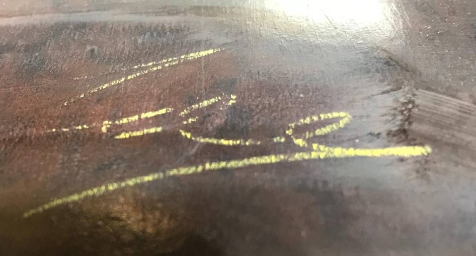
One nice thing I did discover during the disassembly of the receiver was the signature of the person that put the radio together during manufacture on the inside of the Bakelite cabinet.
1946 Philips receiver builder signature
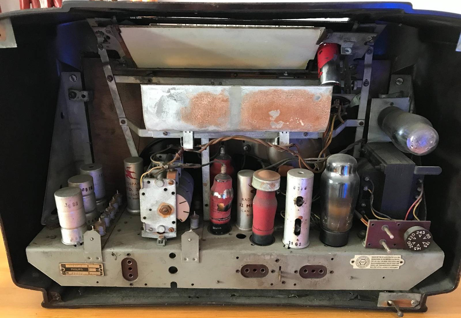
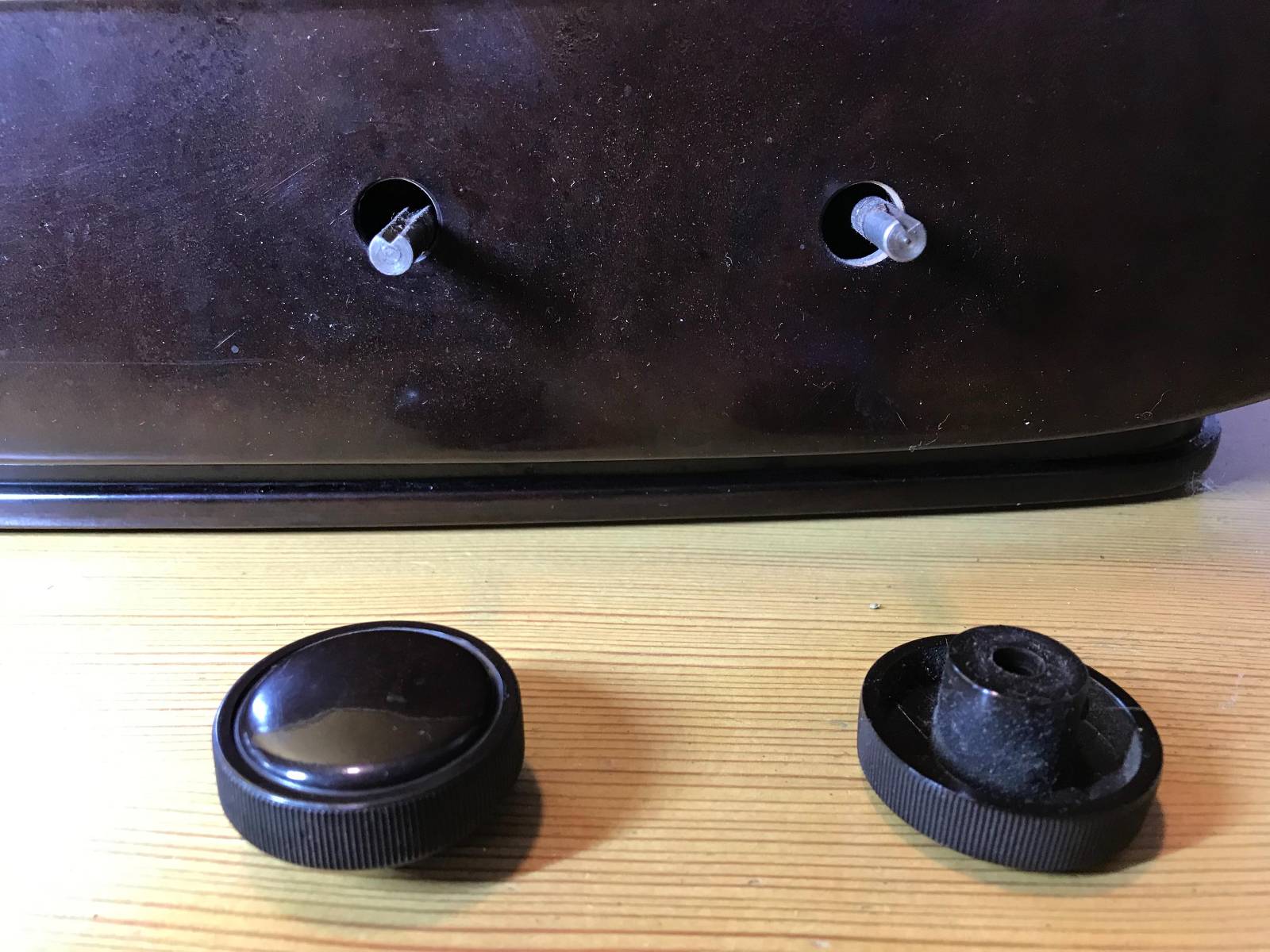
Getting the internals out of the cabinet was fun, so many little screws holding the old valve electronics and tuning display in place.
1946 Philips Receiver – Internal View1946 Philips receiver – removing the original control knobs
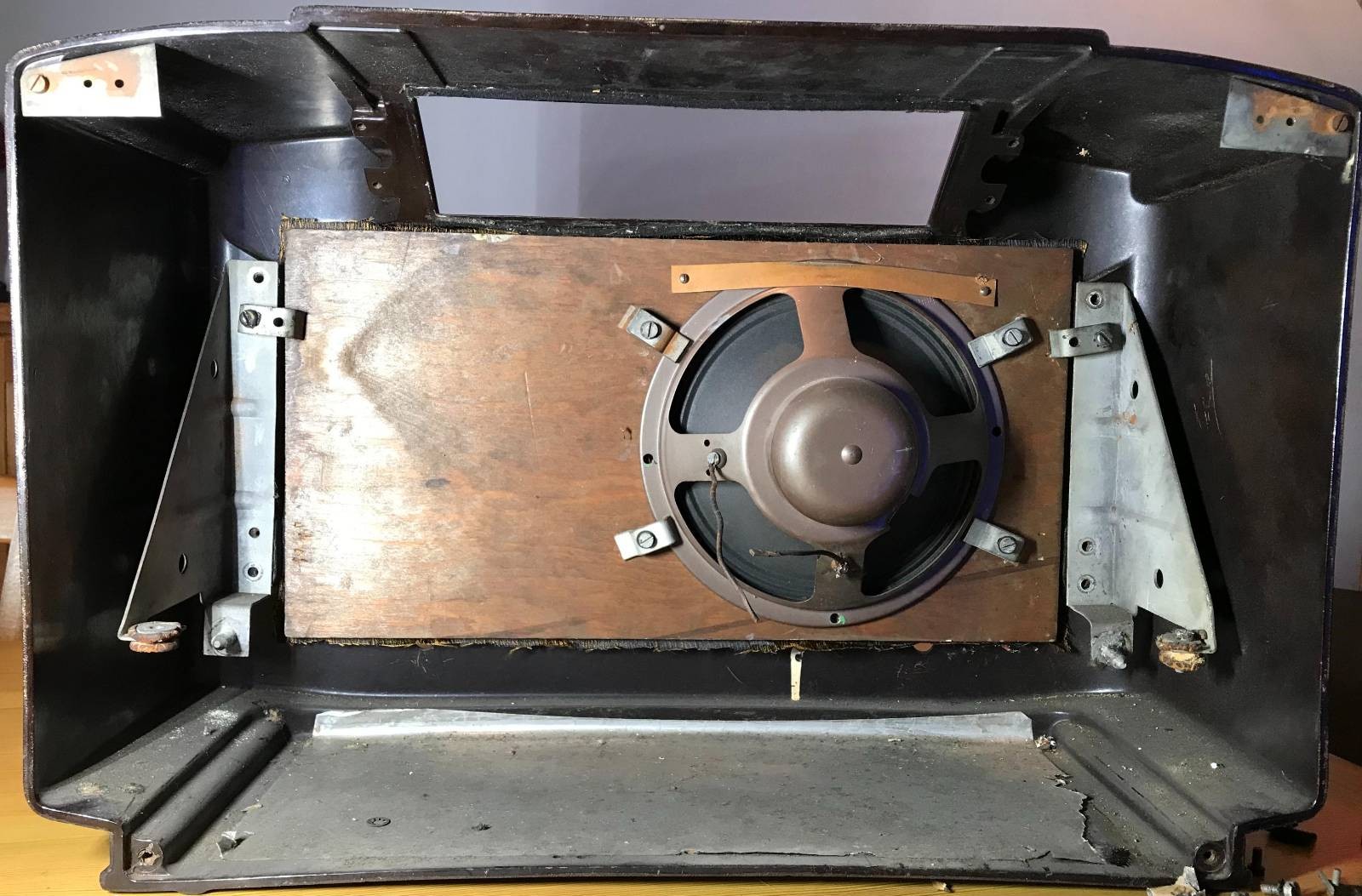
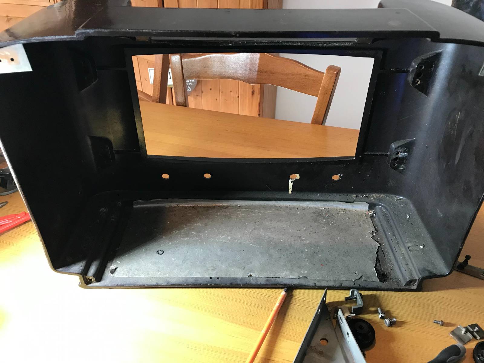
Once the electrical part of the radio was removed I gained access to the old speaker that was fitted to the front panel of the receiver. Unfortunately the speaker cone had a tear in it rendering it useless so I’ll need to get a new speaker(s) for the rebuild.
1946 Philips receiver speaker view
Once I got the speaker and fittings removed I set about cleaning the cabinet inside and out to remove the 79 years worth of dirt and grime that had collected within. The fascia of the receiver cabinet seems to have lost it’s shine and will need to be polished to get it back to it’s original beauty.
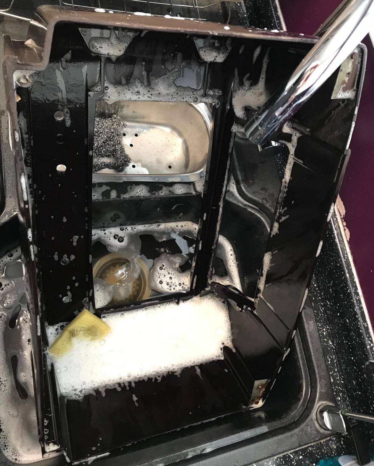
79 years worth of grime and dirt to be removed!Washing the Bakelite receiver case
It took 5 lots of fresh water and washing up liquid to get the cabinet clean. The first three lots of water looked like mud in no time at all such was the state of the cabinet.
With the cabinet now cleaned and put to one side to dry thoroughly I have started to search for the best type of polish to use to put the sheen back onto it.
Once I’ve got the cabinet looking good again I’ll start fitting the new internals. I also need to find a source for a new piece of material to cover the speaker hole at the front of the cabinet as the original material is looking somewhat tired.
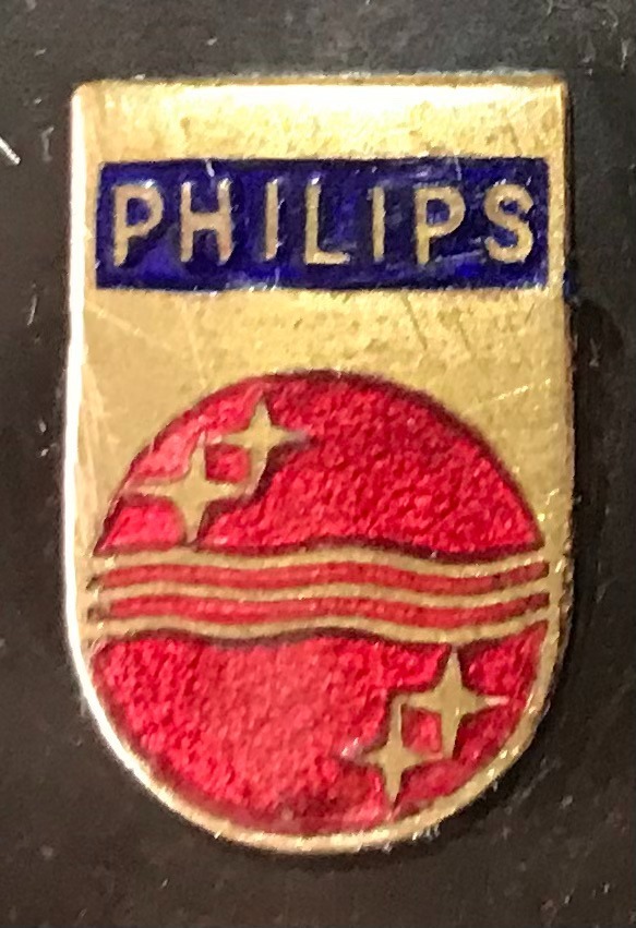
The old Philips Emblem from 1946 on the receiver case
Since I’ve had my Hermes Lite 2 (HL2) and Xiegu XPA125B amplifier combo I’ve had to manually change the band setting on the amp as I never purchased the HL2 I/O board when I initially purchased the kit.
At the time I didn’t think I would need it but, changing band manually on the amp (and sometimes forgetting causing tuning issues) is a nuisance and so I put my hand in my pocket once again and ordered the I/O board for the HL2.
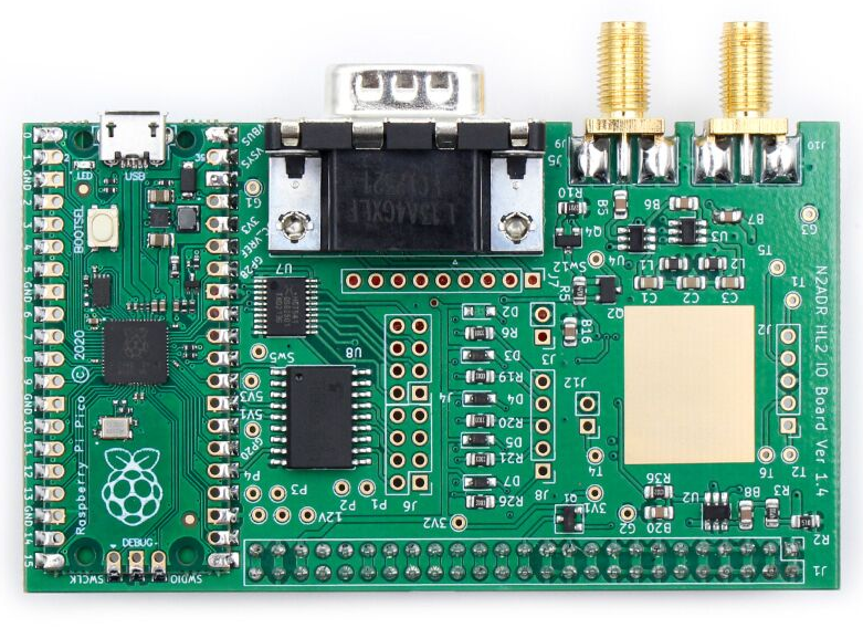
Hermes Lite 2 I/O Board
The HL2 I/O board is a small RaspberryPi Pico controlled device that can be used for a multitude of functions depending on the software loaded. Many people are writing their own software for the Pico to do things like control transverters, remote antenna switches, amplifiers and just about anything else you can think of. It’s a really versatile little add on board for the HL2.
The I/O board arrived after about 10 days from Makerfabs, all nicely packaged as always. Unfortunately due to Christmas, New year and other priorities it’s sat in the box since it arrived.
A couple of days ago I finally got round to getting it out of the box and set about configuring it to control the Xiegu amp.
The Xiegu amp needs three connections from the I/O board. They are PTT, Band Switching Voltage and Ground. These are easily accessed from the I/O board via 3 jumper wires to connect to the DB9 connector on the rear of the board.
The other thing that is required is some software for the RaspberryPi Pico to control the whole process. Steve, M0XVT has kindly supplied me with a copy of the software.
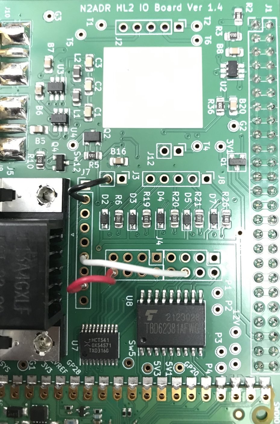
Soldering the jumpers from the relevant points on the circuit board to the DB9 connector was pretty straight forward. You can use any of the pins on the DB9 connector that you like as from the factory the DB9 connector isn’t connected to anything. I decided to use pins 2, 6 and 8 and so will refer to those pins from this point forward.
HL2 I/O Board Jumpers
I used a different colour for each of the jumpers so that I knew which jumper was for which connection. The colours used also match the colours of the wire in the old RS232 serial lead that I cannibalized to make the connection between the I/O board and the amp thus making it easy to ensure continuity.
The colours are as follows:
Black Jumper - Ground - Pin 2 on DB9 Connector
White Jumper - PTT - Pin 6 on DB9 Connector
Red Jumper   - Band Control - Pin 8 on DB9 Connector
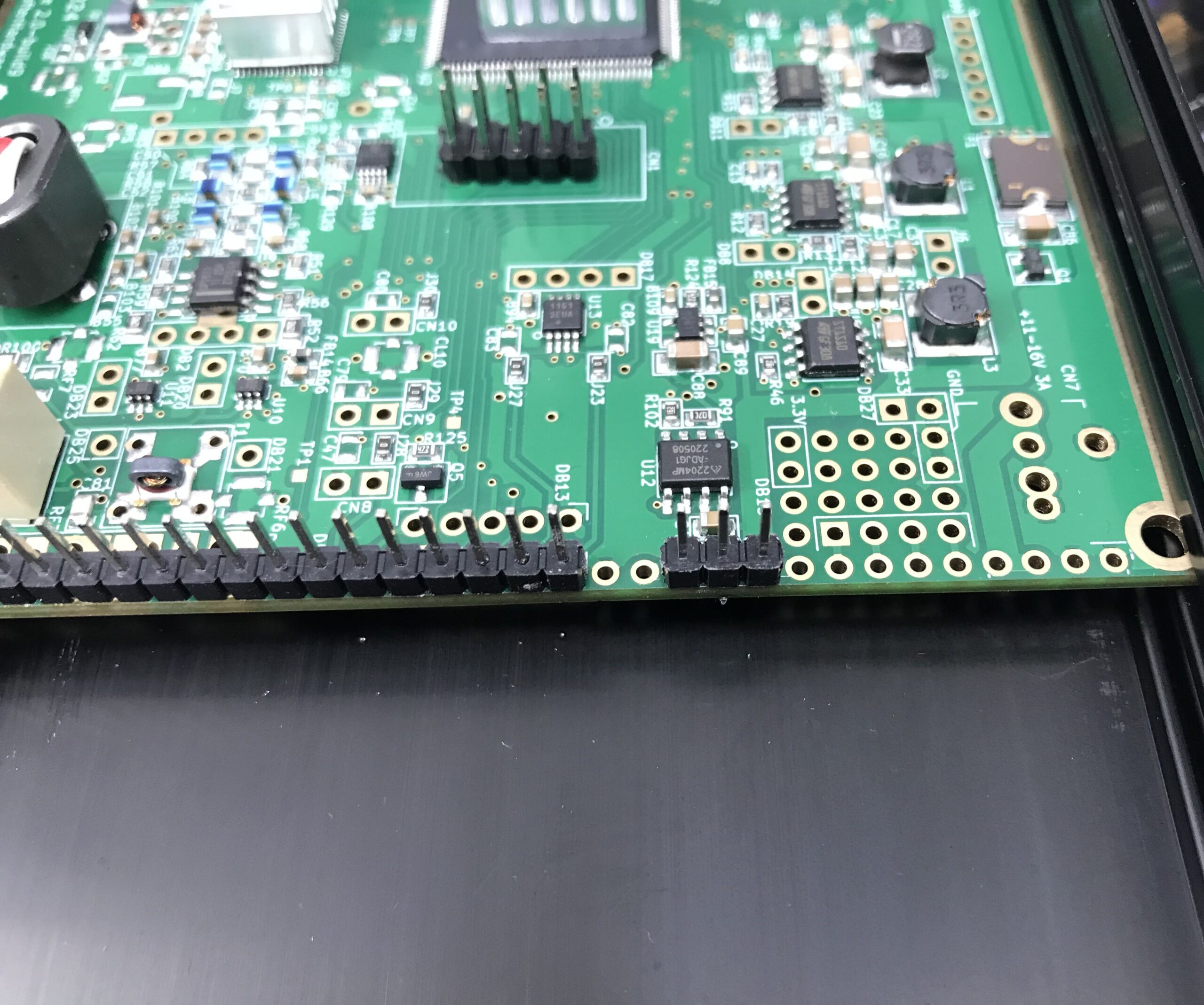
The I/O board gets its power feed directly from the HL2 main board however, the 3 pins it needs to connect to don’t have any headers in place and so, it’s necessary to solder a short row of 3 header pins onto the HL2 main board.
I found the easiest way to do this was to put the 3 header pins into the correct position and then use the HL2 to N2ADR filter board connector to hold them in place whilst soldering. This worked perfectly and I soon had the header pins soldered onto the main board.
Extra 3 header pins soldered to the main HL2 board
It’s important to note that the 3 extra header pins need to be placed 2 holes away from existing header pins as shown above. Take care to get these pins in the right position so as not to cause any damage to the 3 circuit boards once all are connected and powered up.
Note: The HL2 main board must be removed from the case to solder the extra 3 header pins in place. Take care to ensure the correct fitting of the PA heatsink when when refitting the HL2 main board into the case.
At this point I refitted the N2ADR Filter board back into the HL2 case so that the two sets of header pins aligned correctly ready for the placement of the new I/O board that would connect all 3 circuit boards together.
Preparing the N2ADR Filter board for reconnection
Once the filter board was in place I fitted the new I/O board taking care to ensure all pins aligned with the socket and then gently pushed it home.
Close up of the HL2 I/O board fitted to the main HL2 board and N2ADR Filter board
The close up of the I/O board connector above shows how the extra 3 header pins connect to the last 3 sockets in the I/O board connector. It’s a snug fit with the N2ADR filter board below it.
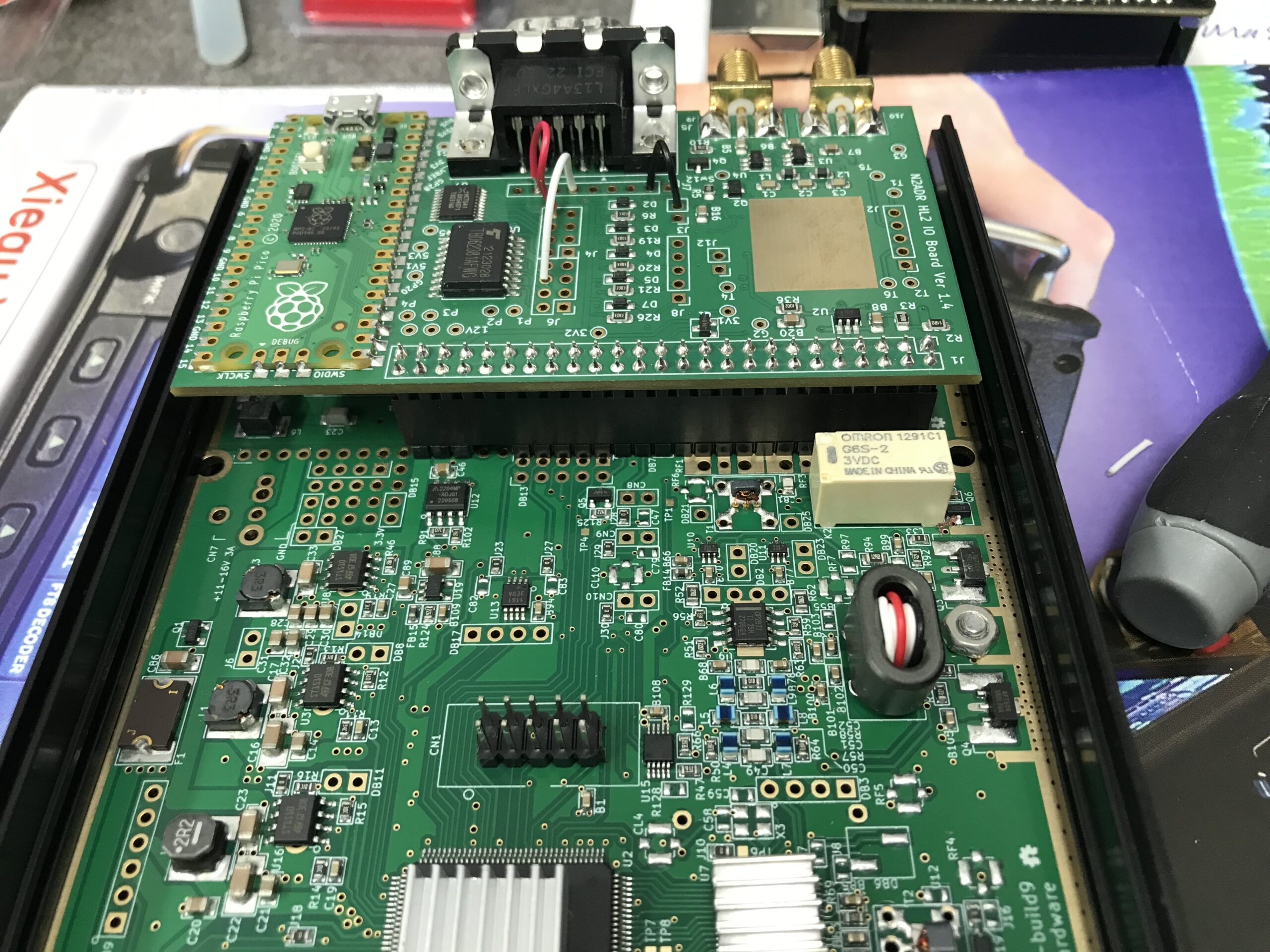
View of the fitted HL2 I/O board from above
Before the HL2 case can be put back together it’s necessary to load the software onto the RaspberryPi Pico (top left in photo above) that controls the I/O board.
This is accomplished by pressing the tiny button on the Pico whilst connecting a USB lead to the USB socket on the board that had already been plugged into my PC. Once connected the Pico appeared as a USB drive on my Kubuntu Linux desktop. All I then had to do was to copy the software file onto the drive. Once the software file is on the drive the Pico will reboot automatically and the little LED on the board will start to flash to show it has booted successfully. At this point I could safely unplug the USB cable.
The software for the RaspberryPi Pico is available for download below.
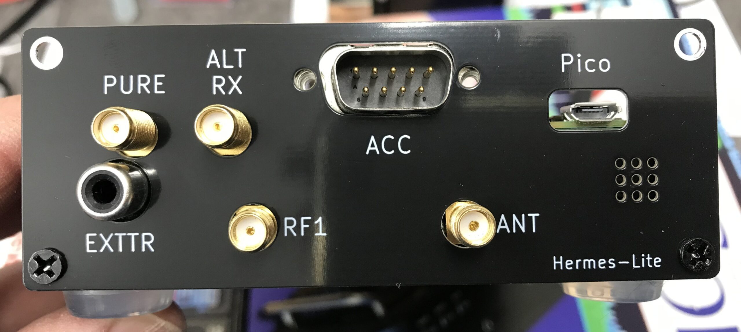
The I/O board comes with a new back panel for the HL2 to accommodate the extra connectors on the rear. Refit the top of the HL2 case and then attach the new rear panel using the original 4 counter sunk screws.
Supplied HL2 I/O board replacement rear panel fitted to the case
The final part of this project is to make the lead that will go from the HL2 rear DB9 ACC connector to the Xiegu XPA125B mini din ACC socket.
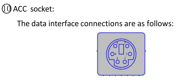
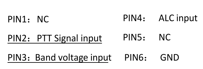
DB9 Pin 2 (BLACK) to Mini Din Pin 6 (GND)
DB9 Pin 6 (WHITE) to mini Din Pin 2 (PTT)
DB9 Pin 8 (RED) to Mini Din Pin 3 (Band Switching Voltage)
Below are a couple of screenshots from the Xiegu XPA125B user manual showing the Mini Din pin layout and the data interface connections for the amplifier.
Before I connected the lead to the two devices, I tested the end-to-end continuity of the lead to ensure all pins were correctly connected and that there were no shorts between any of the pins.
It’s important that the wires are connected to the correct pins on each end of the lead. Failure to ensure correct connection could cause damage to your HL2 and/or amplifier.
Once the lead had been tested, I connected it to both the Hermes Lite 2 and the Xiegu XPA125B amplifier. I also had to switch the amplifier band switching to AUTO.
Now when I change band on my HL2 in the PiHPSDR software the amplifier also changes band at the same time keeping the two devices in sync. No more manual band changing for me!
I hope this article is of use to other Hermes Lite 2 users who have purchased the Xiegu XPA125B but, have yet to setup auto band switching between the two devices.
Thanks to Steve, M0XVT for all the jumper information and the RaspberryPi Pico Software to get this all working.
UPDATE: The RaspberryPi Pico software originally came from Ramon, KP4RX. More information can found in this Google Groups article where he released the binary into the wild.
A full table of I/O resources available on the HL2 I/O board can be found on the KP4RX Guthub page.
The source code for the main.uf2 file above can be found at KP4RX.com
More soon …
We use cookies to ensure that we give you the best experience on our website. If you continue to use this site we will assume that you are happy with it.