There’s always someone listening!

I had a fun day on the radio yesterday. It started with the Matrix QO-100 Satellite Impromptu Net at 16:00 BST on 10489.873Mhz. A net that started off as an impromptu event that over the last couple of years has become a weekly staple. Hardly impromptu at all but, we liked the name and so stuck with it.

During the Impromptu net I noticed that my 2m radio was burbling away in the background and that a lot of European repeaters were coming through so, as soon as the net had finished I quickly switched over to my trusty Wouxun KG-UV980PL and started tuning around the 2m band.

2m was alive with repeaters from France, Belgium, The Netherlands and the UK, often beating against each other on the same frequency.

Being near the East Coast and closer to Belgium than I am to many parts of the UK I jumped onto the ON0WV repeater in Bruges. Being S9+ with me I called a few times but, no one came back to me so, I moved on.

Tuning across my Norwich Repeater memory slot I heard two French stations chatting, it was obvious they weren’t on GB3NB as the bell between overs was not the normal chime.

I quickly opened RepeaterBook on my iPhone and searched for repeaters on the same frequency, there are many!

Eventually I worked out that it was ON0HT so I quickly set about loading the repeater settings into the next available radio memory channel. I loaded a few others from The Netherlands at the same time as I was hearing more than normal from that part of the world.

2 French Operators on the ON0HT repeater in Belgium close to the French border.

Having the correct settings in place for the repeater I was now able to call in and have chat with the two stations.

Jean-Claude F5JOX and Didier F6DKO were surprised to hear an English station call in but, were most welcoming. We had a chat for a few minutes exchanging details and commenting on the great conditions. Sadly the conversation was eventually brought to an end as there were so many repeaters on the same frequency it became impossible for me to hear them clearly so, I gave them 73 and went tuning around.

The 2m band was absolutely full of UK and EU repeaters with many beating against each other on the same frequency. Wouldn’t it be nice if there was more of a split between the UK repeater frequencies and the EU allocation. Would certainly make it easier to use the EU repeaters in lift conditions.

Later in the evening Roger G8VLR, Steve M0XVT and I were having one of our Impromptu Nets on the 60m band. Often there are others from the Matrix that join in too but, on this occasion there were just the 3 of us.

I’m acutely aware that we often have listeners to our on air chats as I quite often get emails from SWL’s and licenced HAMs commenting on how much they enjoy our conversations. Yesterday evening was no exception as it turns out that we were once again attracting listeners albeit, unbeknown to us at the time.

Later in the evening Alan, G1SQB sent me a message via the Matrix with a YouTube link to a recording of us on the 60m band from that very same evening made by @KevinOReillyswl.

Yes, that’s yours truly waffling on about satellites as normal.

Kevin O’Reilly is clearly a very active SWL as he has many interesting videos on his Youtube Channel that are worth a look.

I must confess that I’ve never heard of the MLITE-880 receiver before but, after running a search I found it to be quite a popular radio in the SWL community.

There’s a very good review on swling.com that’s worth a read.

The short video above shows it to be a surprisingly good shortwave receiver in a very compact, portable package that’s ideal for listening whilst out and about on camping trips or other outdoor activities.

A big thanks to Kevin O’Reilly for posting the video and letting us see how we sound on the other end.

More soon …

Xiegu XPA125B Button Press

For some time now I’ve been using my Xiegu XPA125B amplifier with my Hermes Lite 2 + I/O board combo with great success. With the amp changing bands automatically it really is nice to use.

With the multitude of remote controlled smart plugs available today I’ve now got the ability to switch the station on remotely however, there’s been one issue that has plagued me until now and that’s the Xiegu amp doesn’t come on when power is applied to it, you have to press the power button on the front of the amp before it will fire up.

This of course stops me from being able to fully use the station remotely as there’s no one there to press the power button on the amp, until now.

Chatting with Steve, M0XVT he discovered that if the power button is held pressed all the time the amp will come on when power is applied. This then gave me the idea of designing a button press device that I could 3D print and clip onto the front of the amp so that the button is always pressed.

M0AWS Xiegu XPA125B Clip on Power Button Press

The Xiegu amp has a very nice flange around the front edge of the amp case that lends itself nicely to clip on a simple button press device as shown above in my 3D design software.

The button press is designed so that the top is put on first and then the bottom is just snapped into place with a gentle push. This makes it easy to get on and off without marking the amplifier.

M0AWS Xiegu XPA125B Clip on Power Button Press

In just a few minutes I had the button press design uploaded to my Bambu Lab A1 Combo 3D printer and in no time at all the button press was ready for use.

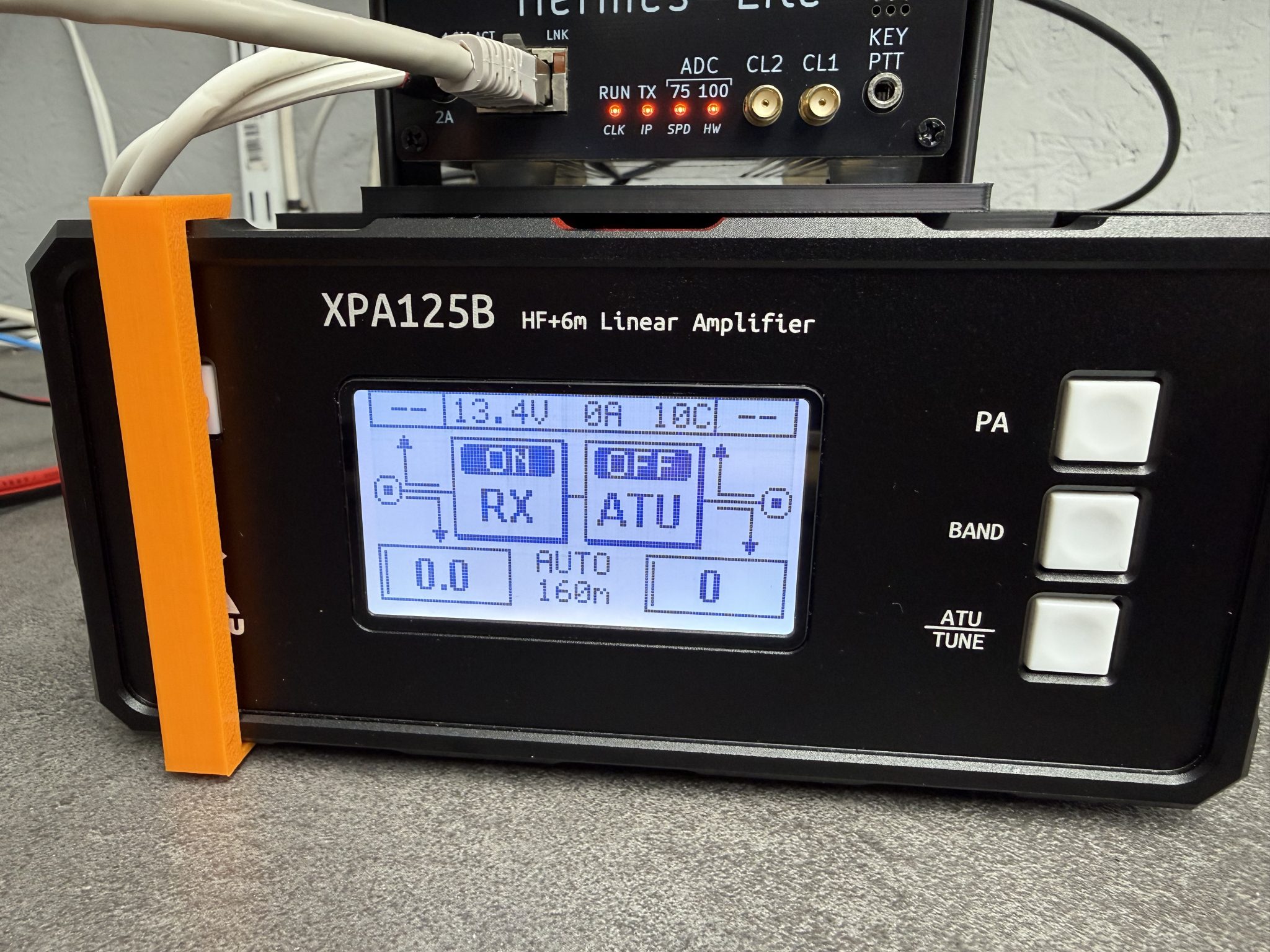
As you can see in the photo above it fits snugly to the front of the amp gently holding the power button in so that the amp comes on when power is applied. Simple but, effective.

I’m sure I’m not the first person to have this problem and so, I’ve made the .STL 3D print file available for download below.


I hope this is of use to people who want to be able to use their Xiegu amp remotely without leaving the power on all the time.

More soon …

Rescuing a Bricked Pluto+

I’ve not written an article on the blog for a while now mainly because I’ve not had anything interesting to write about.

Today that changed, as I had a fun little project to dive into.

Steve, M0XVT sent me his Pluto+ SDR transceiver after his rather unsuccessful attempt at updating the firmware. Long story short, he somehow managed to brick the Pluto+ rendering it completely useless.

Not having a Pluto+ myself I’ve never actually played with one before and so this was new and exciting. I have, however played with Steve’s LibreSDR which is a later iteration of the Pluto+ and so, I had an idea of what I was getting into.

Firstly, how do you know when you have bricked your Pluto+?

Fortunately the Pluto+ device is actually quite clever and will inform you when it is bricked. The first sign you will notice is that you can no longer connect to the device using a USB connection to the data socket. The second sign is that when you take the top off the case you’ll notice that the blue LED is off and the green LED is on constantly. These are both classic signs that the device is bricked and needs rescuing

So, how do we rescue a bricked Pluto+?

Firstly, disconnect all cables and power to the device, it needs to be in a powered down state. Next remove the top of the case completely.

Unlike the LibreSDR the Pluto+ doesn’t boot from SD card so, we have to tell it that we want to boot it from an SD card. This is done by shorting the 3v3 and SD-H pins together using a jumper as shown in the photo below. (Black Jumper)

Pluto+ 3v3 and SD-H pins shorted together by black jumper

I believe that the v1 version of the Pluto+ has 1.8v instead of 3.3v, if this is the case on your device just short the SD-H pin to the 1v8 pin instead.

Next we need to make sure that the URST pin is connected to the MIO46 pin as shown by the green jumper in the image above. I put the jumper into this position as I am going to be using firmware that has ethernet support built in. If you want to load the official firmware then you will need to connect the URST pin to the MIO52 pin instead.

Next we need to load the new firmware onto an appropriate SD card. I’m using the F5OEO firmware that has ethernet support with DHCP built in. You can get the firmware from this Github link.

Whilst the firmware is downloading, insert your SD card into your PC and format it using a FAT32 filesystem.

Once the firmware has downloaded, unzip the file and save the contents of the zip file to a directory. Using your favourite file manager or in the case of a Linux junkie like me, the command line, copy the contents of the sdimg folder into the root of the SD card.

Note: That’s copy of the contents of the sdimg folder, not the folder itself.

Make sure to eject your SD card safely before removing it from your PC to ensure you don’t corrupt the contents.

Insert the SD card into the Pluto+ (it’s still powered down at this point with the top off).

Plug the USB A end of the USB cable into your PC but, do not plug the micro USB end into the Pluto+ just yet!

Now this is the tricky part, you need to hold down the DFU Button on the Pluto+ PCB (It’s behind the professor image on the PCB) whilst inserting the micro-USB plug into the DATA port of the Pluto+.

Once you see that the green and blue LED lights come on permanently, let go of the DFU Button and let the Pluto+ boot from the SD card. A short while afterwards the green LED should start flashing, this means your Pluto+ is alive again and has booted from the SD card.

At this point it’s important not to unplug the USB cable and not to remove the SD card from the device, we’re only half way there!

After a little more time the Pluto+ will appear in your file manager as a drive called PlutoSDR, navigate to this drive using your favourite file manager.

At the same time, open another window in your file manager and navigate to the folder where you saved the files from the Zip file. In this directory you will see the following two files:

boot.frm
pluto.frm

Copy these two files from the directory where you saved them into the root of the PlutoSDR drive.

Once this is complete, eject the PlutoSDR drive safely.

The green LED will now start blinking, don’t do anything, just leave everything as it is and the device will now create a new boot image on it’s own built in storage.

This process will take about 5mins so, go grab a cold beer, glass of wine or anything else that takes your fancy, sit back and relax.

Eventually the green LED will stop flashing, wait another minute or so for the process to fully complete.

If the PlutoSDR drive has reappeared in your file manager, safely remove the drive from your file manager and unplug the micro USB connector from the Pluto+ powering it down.

It’s now important to remove the 3v3 to SD-H jumper as we no longer need to boot from SD card.

You can now refit the top cover and the 4 screws and put the case back together. Connect an ethernet cable and micro USB cable to the DATA port and wait.

After about 10-15 seconds the green LED should flash and your Pluto+ is now no longer bricked and ready for use once more.

You can SSH to your Pluto+ using the normal Linux SSH command logging in as root with a password of analog.

If you have PiHPSDR installed and compiled with the SOAPYSDR library and modules (See my article on how to do this easily) you can now start it and connect to your Pluto+ device as normal.

Steve's rescued Pluto+ receiving a signal from my AllStarLink node in PiHPSDR
Steve’s rescued Pluto+ receiving a signal on the 70cm band

This same procedure can be used on Linux, Mac, Windows and RaspberryPi, it is not platform dependent.

If you want your Pluto+ to always boot from the SD card, you can leave the 3v3 pin connected to the SD-H pin permanently.

More soon ….

Hermes Lite 2 and Xiegu XPA125B Auto Band Switching

Since I’ve had my Hermes Lite 2 (HL2) and Xiegu XPA125B amplifier combo I’ve had to manually change the band setting on the amp as I never purchased the HL2 I/O board when I initially purchased the kit.

At the time I didn’t think I would need it but, changing band manually on the amp (and sometimes forgetting causing tuning issues) is a nuisance and so I put my hand in my pocket once again and ordered the I/O board for the HL2.

Hermes Lite 2 I/O Board

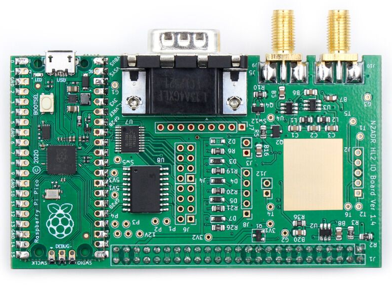
The HL2 I/O board is a small RaspberryPi Pico controlled device that can be used for a multitude of functions depending on the software loaded. Many people are writing their own software for the Pico to do things like control transverters, remote antenna switches, amplifiers and just about anything else you can think of. It’s a really versatile little add on board for the HL2.

The I/O board arrived after about 10 days from Makerfabs, all nicely packaged as always. Unfortunately due to Christmas, New year and other priorities it’s sat in the box since it arrived.

A couple of days ago I finally got round to getting it out of the box and set about configuring it to control the Xiegu amp.

The Xiegu amp needs three connections from the I/O board. They are PTT, Band Switching Voltage and Ground. These are easily accessed from the I/O board via 3 jumper wires to connect to the DB9 connector on the rear of the board.

The other thing that is required is some software for the RaspberryPi Pico to control the whole process. Steve, M0XVT has kindly supplied me with a copy of the software.

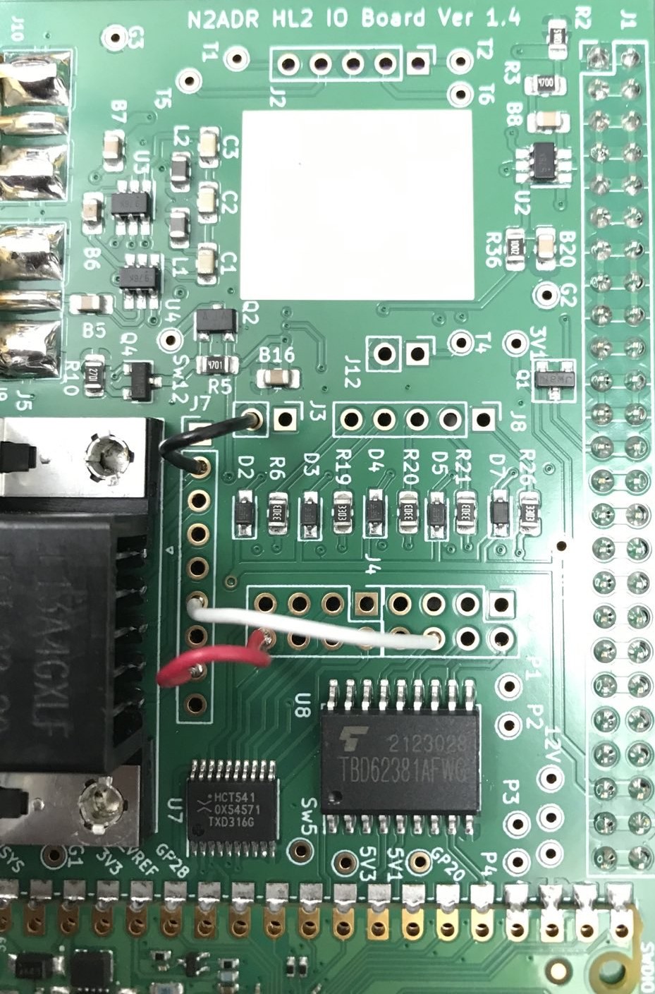
Soldering the jumpers from the relevant points on the circuit board to the DB9 connector was pretty straight forward. You can use any of the pins on the DB9 connector that you like as from the factory the DB9 connector isn’t connected to anything. I decided to use pins 2, 6 and 8 and so will refer to those pins from this point forward.

HL2 I/O Board Jumpers

I used a different colour for each of the jumpers so that I knew which jumper was for which connection. The colours used also match the colours of the wire in the old RS232 serial lead that I cannibalized to make the connection between the I/O board and the amp thus making it easy to ensure continuity.

The colours are as follows:

Black Jumper - Ground - Pin 2 on DB9 Connector
White Jumper - PTT - Pin 6 on DB9 Connector
Red Jumper   - Band Control - Pin 8 on DB9 Connector

The I/O board gets its power feed directly from the HL2 main board however, the 3 pins it needs to connect to don’t have any headers in place and so, it’s necessary to solder a short row of 3 header pins onto the HL2 main board.

I found the easiest way to do this was to put the 3 header pins into the correct position and then use the HL2 to N2ADR filter board connector to hold them in place whilst soldering. This worked perfectly and I soon had the header pins soldered onto the main board.

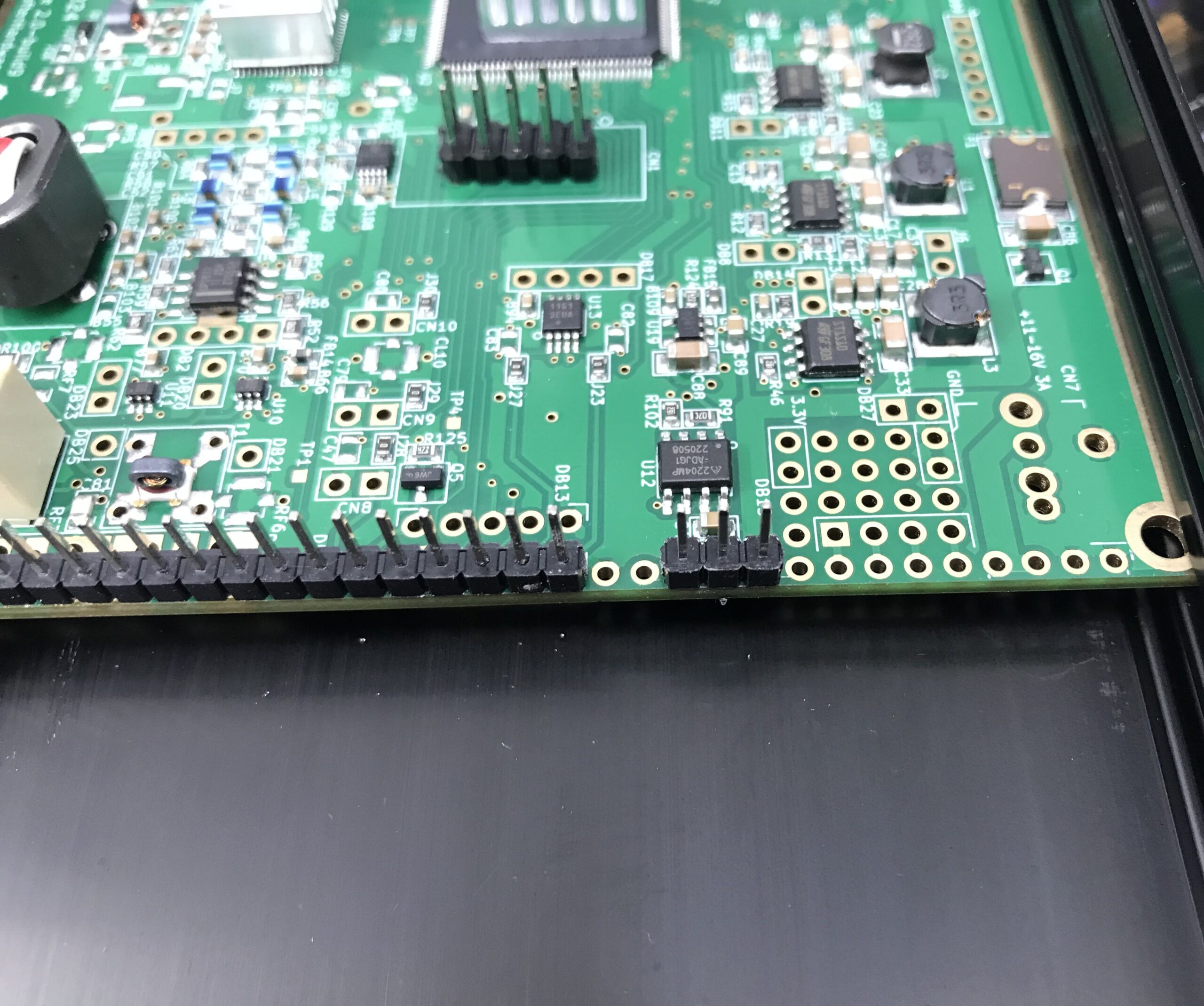
Extra 3 header pins soldered to the main HL2 board

It’s important to note that the 3 extra header pins need to be placed 2 holes away from existing header pins as shown above. Take care to get these pins in the right position so as not to cause any damage to the 3 circuit boards once all are connected and powered up.

Note: The HL2 main board must be removed from the case to solder the extra 3 header pins in place. Take care to ensure the correct fitting of the PA heatsink when when refitting the HL2 main board into the case.

At this point I refitted the N2ADR Filter board back into the HL2 case so that the two sets of header pins aligned correctly ready for the placement of the new I/O board that would connect all 3 circuit boards together.

Preparing the N2ADR Filter board for reconnection

Once the filter board was in place I fitted the new I/O board taking care to ensure all pins aligned with the socket and then gently pushed it home.

Close up of the HL2 I/O board fitted to the main HL2 board and N2ADR Filter board

The close up of the I/O board connector above shows how the extra 3 header pins connect to the last 3 sockets in the I/O board connector. It’s a snug fit with the N2ADR filter board below it.

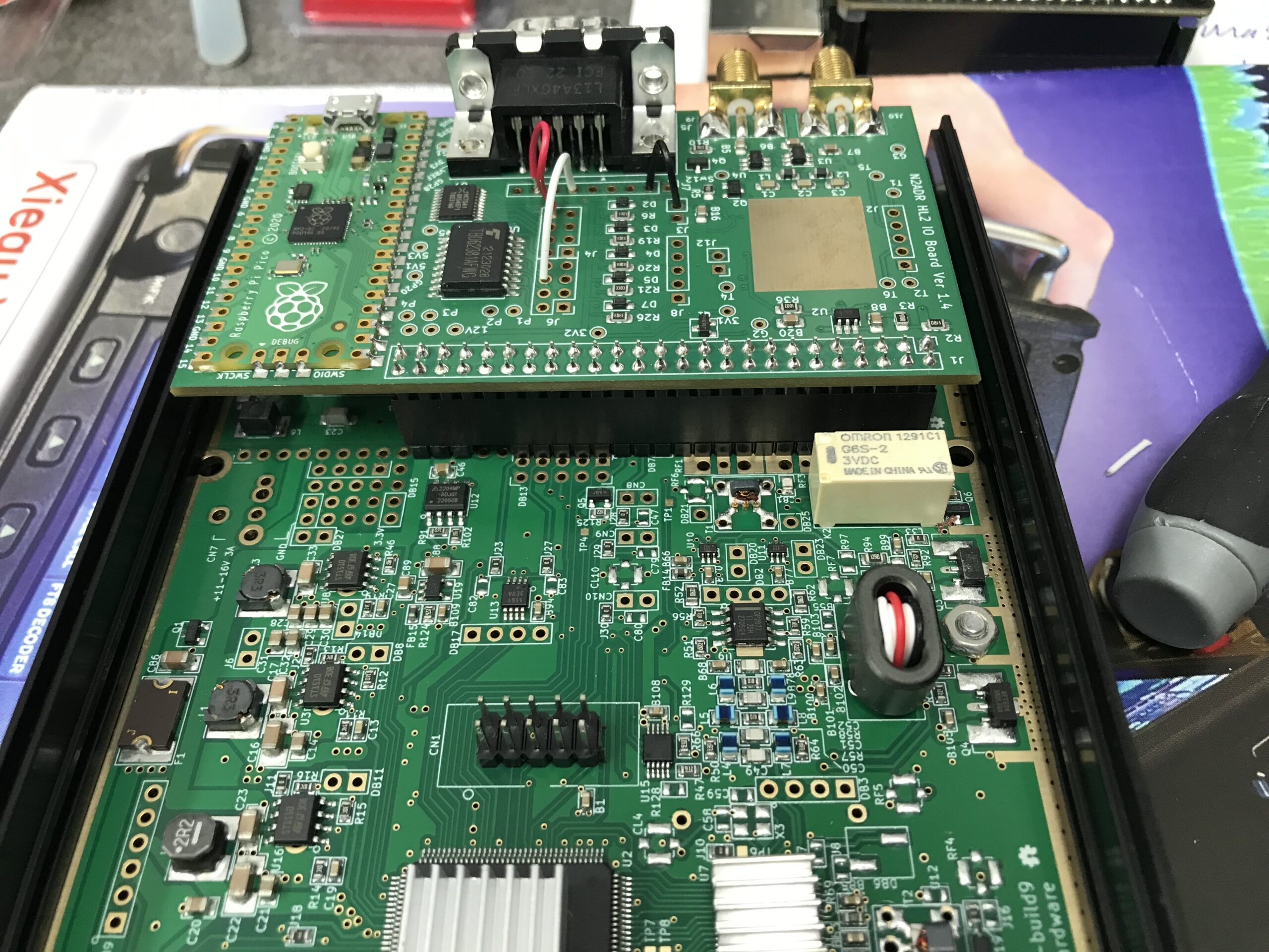
View of the fitted HL2 I/O board from above

Before the HL2 case can be put back together it’s necessary to load the software onto the RaspberryPi Pico (top left in photo above) that controls the I/O board.

This is accomplished by pressing the tiny button on the Pico whilst connecting a USB lead to the USB socket on the board that had already been plugged into my PC. Once connected the Pico appeared as a USB drive on my Kubuntu Linux desktop. All I then had to do was to copy the software file onto the drive. Once the software file is on the drive the Pico will reboot automatically and the little LED on the board will start to flash to show it has booted successfully. At this point I could safely unplug the USB cable.

The software for the RaspberryPi Pico is available for download below.


The I/O board comes with a new back panel for the HL2 to accommodate the extra connectors on the rear. Refit the top of the HL2 case and then attach the new rear panel using the original 4 counter sunk screws.

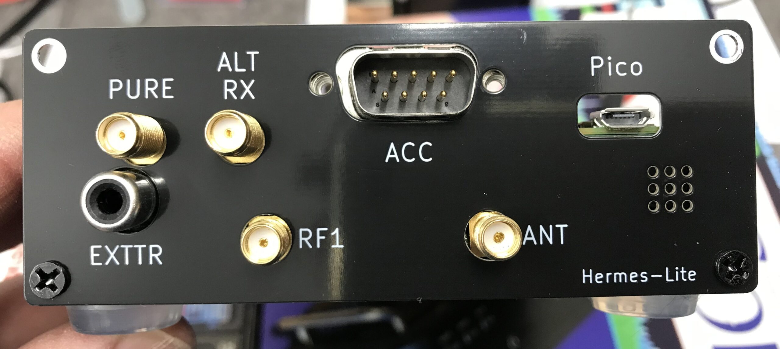
Supplied HL2 I/O board replacement rear panel fitted to the HL2 case
Supplied HL2 I/O board replacement rear panel fitted to the case

The final part of this project is to make the lead that will go from the HL2 rear DB9 ACC connector to the Xiegu XPA125B mini din ACC socket.

For this you will need a 6 pin mini din plug (AKA PS2 plug), (these are readily available on Amazon) and an old fashioned DB9 female connector from the days of RS232 serial leads..

The connections are as follows:

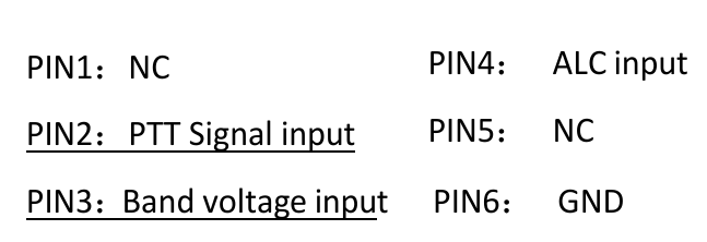
DB9 Pin 2 (BLACK) to Mini Din Pin 6 (GND)
DB9 Pin 6 (WHITE) to mini Din Pin 2 (PTT)
DB9 Pin 8 (RED) to Mini Din Pin 3 (Band Switching Voltage)

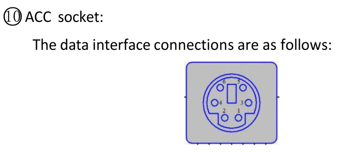
Below are a couple of screenshots from the Xiegu XPA125B user manual showing the Mini Din pin layout and the data interface connections for the amplifier.

Xiegu XPA125B Amplifier ACC Interface Connections
Xiegu XPA125B Amplifier ACC Connector Pin Information

Before I connected the lead to the two devices, I tested the end-to-end continuity of the lead to ensure all pins were correctly connected and that there were no shorts between any of the pins.

It’s important that the wires are connected to the correct pins on each end of the lead. Failure to ensure correct connection could cause damage to your HL2 and/or amplifier.

Once the lead had been tested, I connected it to both the Hermes Lite 2 and the Xiegu XPA125B amplifier. I also had to switch the amplifier band switching to AUTO.

Now when I change band on my HL2 in the PiHPSDR software the amplifier also changes band at the same time keeping the two devices in sync. No more manual band changing for me!

I hope this article is of use to other Hermes Lite 2 users who have purchased the Xiegu XPA125B but, have yet to setup auto band switching between the two devices.

Thanks to Steve, M0XVT for all the jumper information and the RaspberryPi Pico Software to get this all working.

UPDATE:
The RaspberryPi Pico software originally came from Ramon, KP4RX. More information can found in this Google Groups article where he released the binary into the wild.

A full table of I/O resources available on the HL2 I/O board can be found on the KP4RX Guthub page.

The source code for the main.uf2 file above can be found at KP4RX.com

More soon …