Building MB7IBW 2m AllStarLink Internet Gateway

I’ve recently built another AllStarLink node to compliment my personal 70cm band SHARI node as I thought since I have a full duplex dual band handheld it would be great to have another node that I could connect to FreeStar or HUBNet at the same time as monitoring the Matrix node.

Rather than build another personal node I decided this time I would build a public node, obtain a callsign from the RSGB and make it available to the HAM’s locally on the 2m band.

This would make it possible for me to monitor both nodes at the same time using my Wouxun KG-UV9K full duplex dual band handheld whilst providing the local HAM community with access to the AllStarLink network.

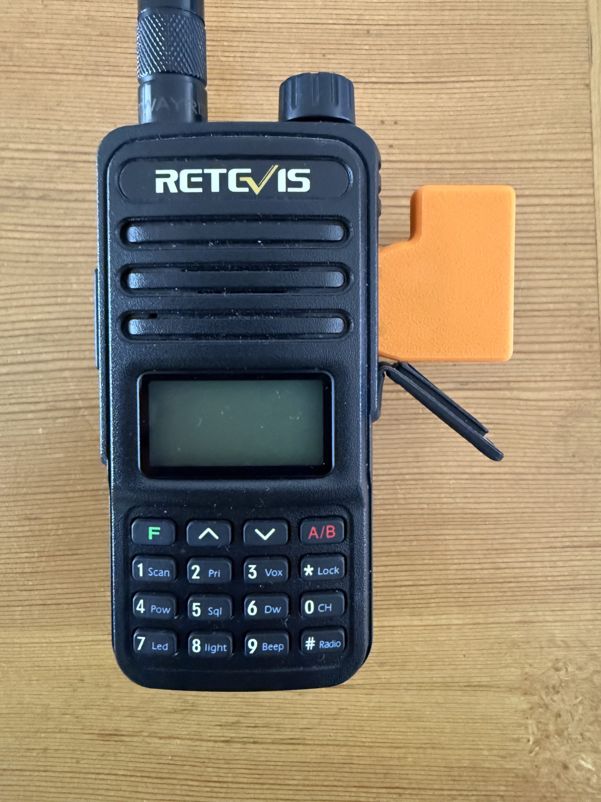
Initially I thought I may be able to use my old Retevis RT85 handheld and AIOC board for the 2m node but, after a little testing it soon became apparent that it overheats during long overs (which are common on AllStarLink) and so, I needed to find another solution.

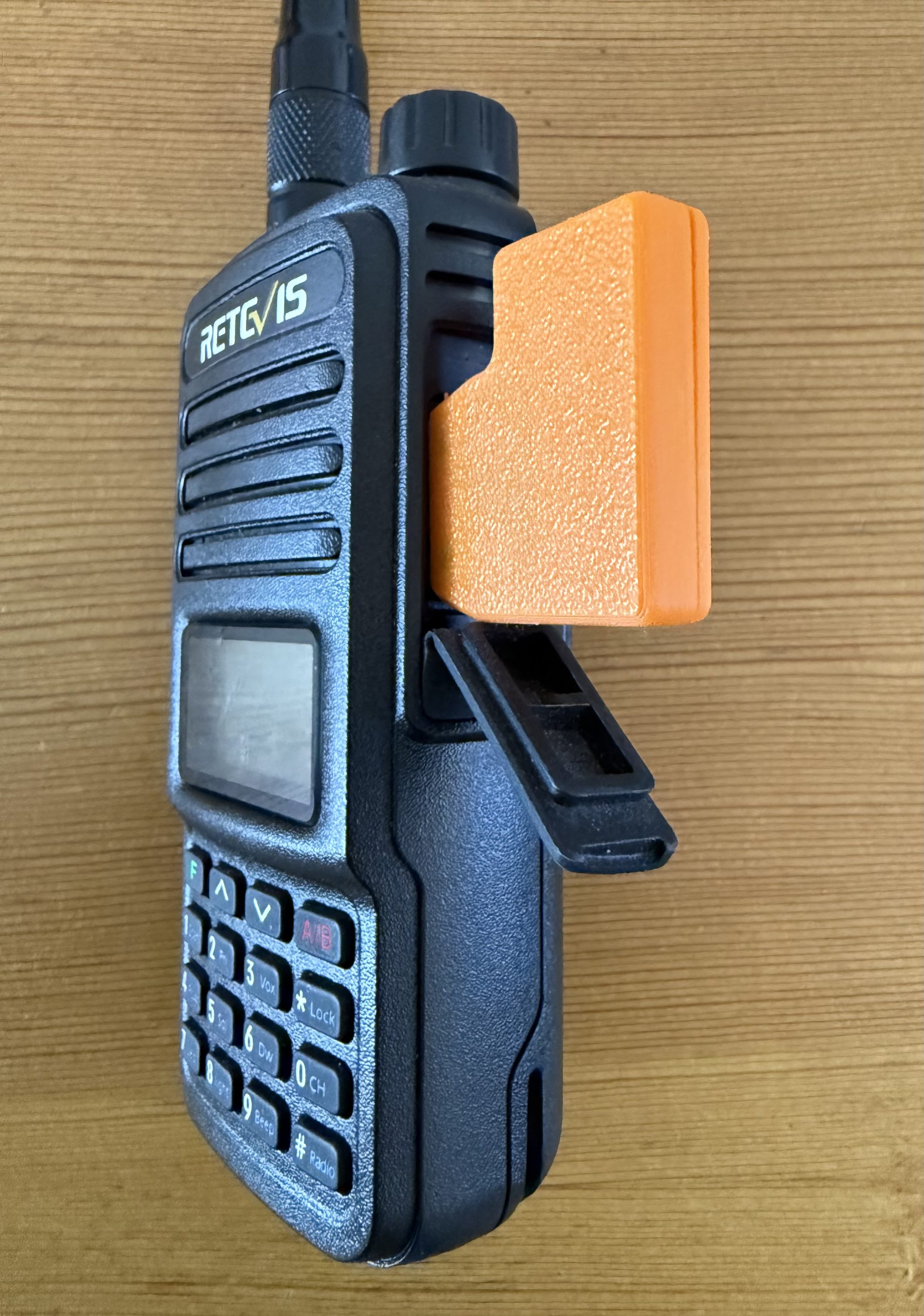
AIOC connected to the Retevis RT85.

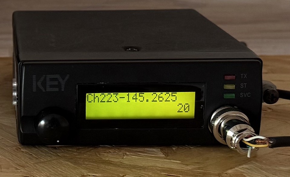
Chatting about this in the main Matrix HAM Radio room Steve, M0XVT sent me a message saying he had an old Key KM-4000 converted PMR radio that had been reprogrammed for the 2m band that he was looking to sell and that it might be ideal for the new node. Wasting no time, we came to an agreement and I was soon the proud owner of a converted PMR transceiver.

Key KM4000 2m Band PMR Radio

The KM4000 transceiver has a standard output of 15w, 10w more than I needed for the gateway and so I had to reduce the output. A quick search on the internet and I found the Thames Valley Repeater Group website that had all the information required to turn down the output.

I also had to reprogramme channel 1 to the frequency and CTCSS tone allocated to me by the RSGB so that in the event of a power outage when the radio came back on it automatically jumps to channel 1 which would be correctly setup for operation.

Unfortunately the software for programming the radio is only available for windows and so I had to build a virtual machine running windows 10 to be able to reprogramme the radio.

Once this was done I rewired the AIOC USB audio device to work with the KM4000 radio and built the AllStarLink node on a spare RaspberryPi 4.

For an antenna I made a simple end fed vertical dipole from some RG58 coax and mounted it 8m up on one of my Spiderpoles in the garden. Running a coax feed out to the antenna I did some tests into the Parrot to get the audio levels setup and checked that the DTMF codes were interpreted correctly and that the node switched connections without error.

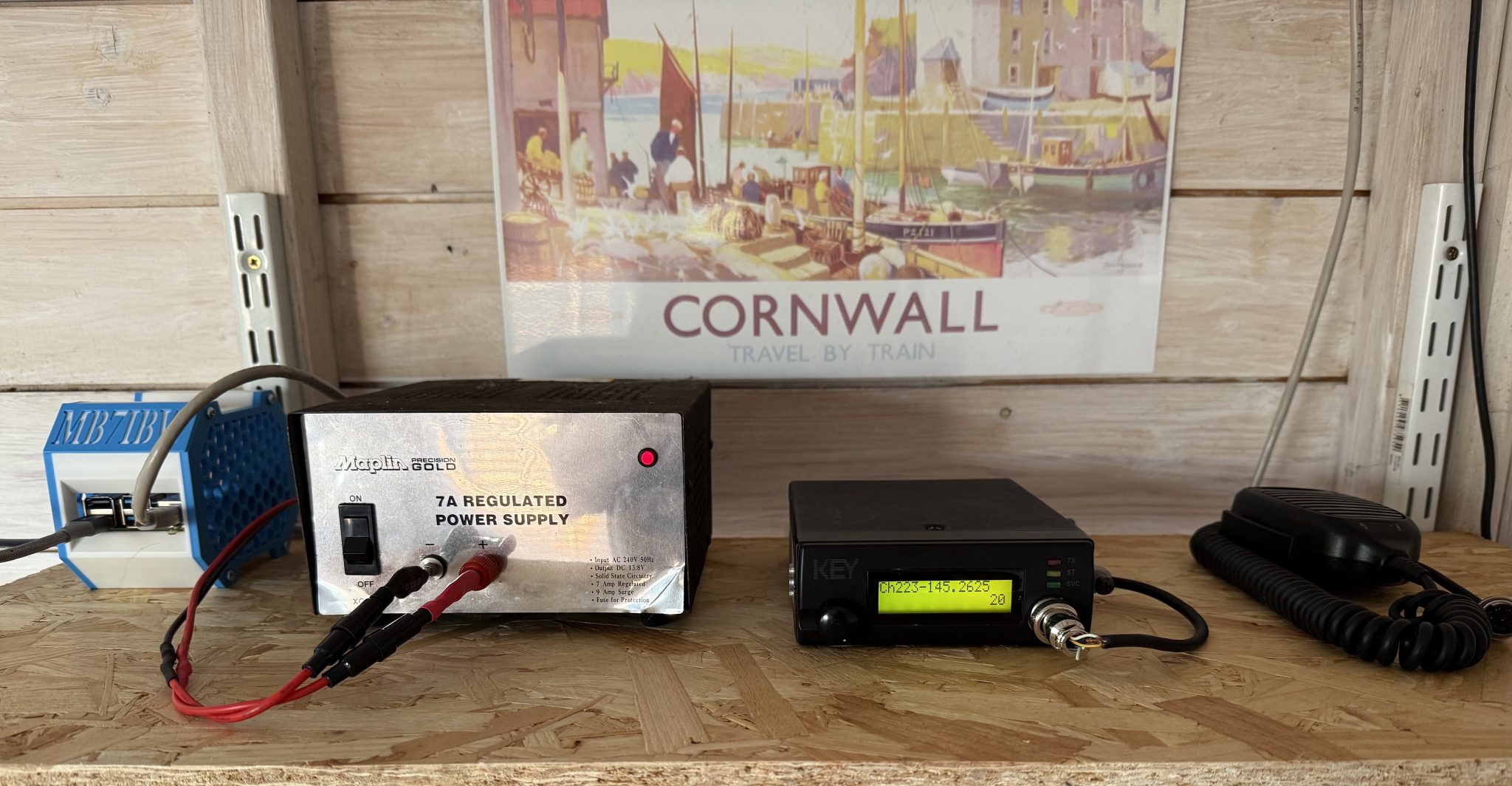
MB7IBW Internet Gateway hardware at the M0AWS QTH

Once this was done I had a few test conversations with stations on the Matrix node and FreeStar to ensure all was fine and then set the gateway status to “Operational” on the RSGB website.

This worked fine for a while with myself and some local stations using the node regularly but, then the hot weather arrived and things started to overheat. The transceiver was getting incredibly hot in the 30c+ summer temperatures and the power supply was also running extremely hot and so I decided to add some cooling.

Cooling the PSU was simple, it has a perforated top panel to which I strapped a cooling fan. This worked great and brought the temperature of the PSU down considerably.

The radio wasn’t so easy to cool. It has a solid case cover top and bottom and so cooling wasn’t going to be a simple affair.

I decided to remove the covers and drill some holes into them to allow airflow through the unit and strapped a fan to the top cover to pull the hot air out. This worked well however, on both transmit and receive I now had a warbling sound on the audio that was caused by the motor of the fan when powered up.

I found that lifting the fan up away from the case of the radio the warbling audio disappeared and things were back to normal and so, I decided to design a cooling tube to fit to the top of the radio to allow full airflow from the fan but, with the fan raised up away from the radio to resolve the audio problem.

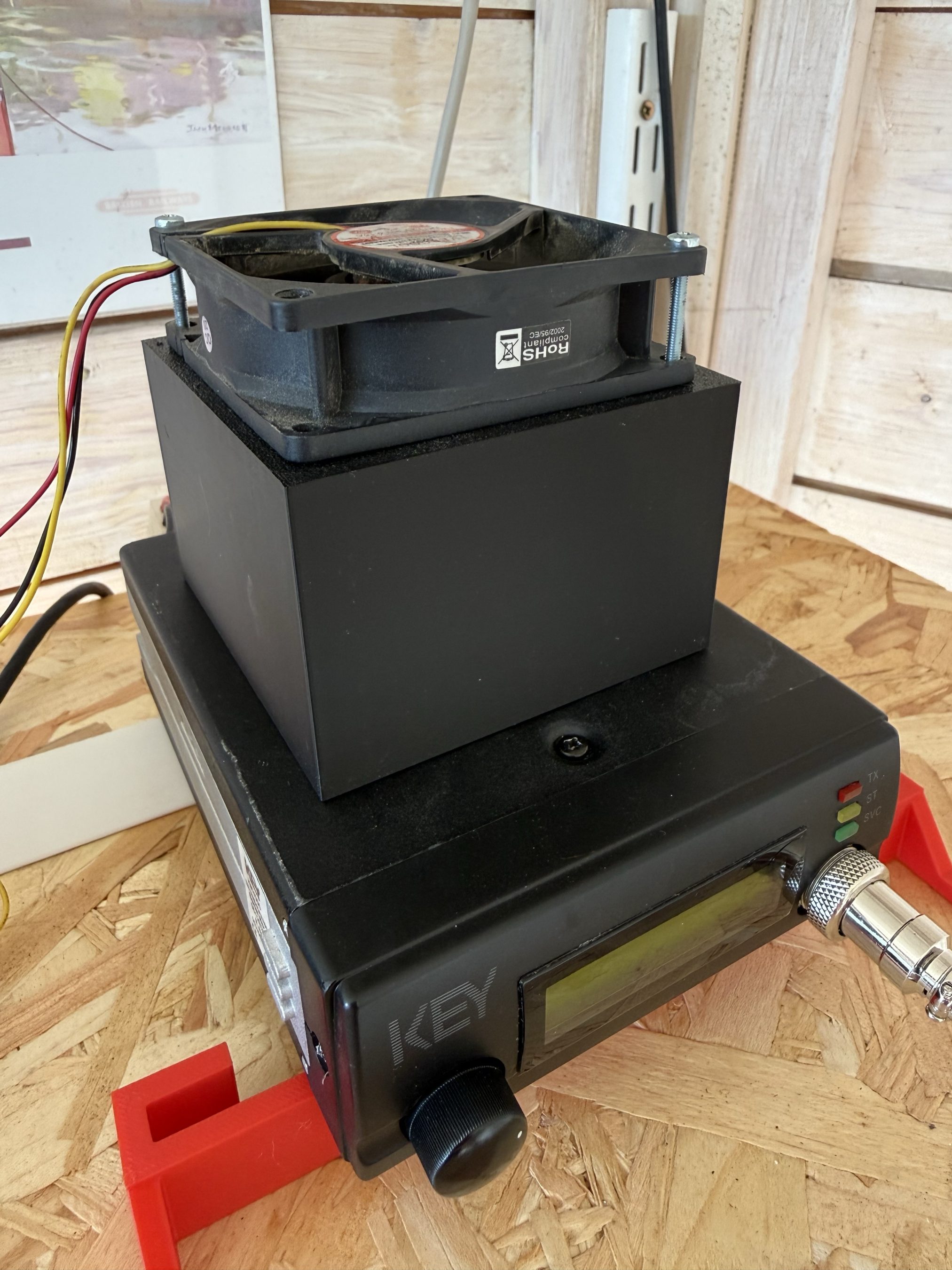
Jumping into my CAD software I quickly designed a cooling tower to fit on the top of the radio that would allow the fan to sit far enough away from the radio so as to not affect the audio whilst at the same time pulling the hot air out of the radio and drawing cooler air in through the bottom of the case.

I sent the design through to my Bambu Lab A1 Combo 3D printer and set the print job running.

Key KM4000 Cooler
Key KM4000 Cooler

The cooler worked great with the radio staying cool to the touch and no longer overheating and reducing O/P power.

It’s amazing how much dust and dirt is in the air from all the farming activities going on at the end of our garden and how much of it is sucked in by the cooling fan. Regular cleaning is a must!

The MB7IBW Internet Gateway has been on air since mid June 2026 and has worked well. It spends most of its time connected to either FreeStar or HUBNet with connections to the Matrix Node when we have our nets.

Details on Frequency, CTCSS etc can be found under the MB7IBW menu above.

Sadly the initial interest from local HAMs has now wained and I am mostly the only user of the gateway. I was hoping more people would use it and bring some life to the 2m band, I guess time will tell.

It’s been a fun project and was interesting to go through the callsign allocation process with the RSGB representative. It was much easier than I thought it would be.

I now have all the parts to build another Internet Gateway for the 4m band. Hopefully that may attract some more interest. It’s certainly worth a try!

More soon …

Bring your old handheld to life with an AIOC

I’m sure there are many radio amateurs around the world today who have an old handheld radio sat on the shelf that works perfectly but, has been replaced by a new, shiny, all singing, all dancing model that gets used on a daily basis. I for one have fallen into this trap with the recent purchase of a very nice Wouxun KG-UV9K full duplex 2m and 70cm handheld.

On my shelf there is a cheap Retevis RT85 that gave sterling service for a number of years and even today is ready to continue that service, if only I had a need?

Well now I do!

Currently I have an AllStarLink node running on a RaspberryPi 3b connected to a SHARI device that operates on the 70cm band. This node works great and gives me the ability to chat with people all over the world from my trusty handheld. It does of course also give me access to the weekly Matrix AllStarLink Net that happens on our Matrix node ( 642332 ) every Thursday evening at 20:00 UK time, a great way of bringing the Matrix HAM Radio community together regardless of propagation.

For some time I’ve been wanting to bring another AllStarLink node online so that I can have a connection to HUBNET/FreeNet whilst keeping my current node connected to the Matrix node for our regular daily chats. Since my new Wouxun handheld is a full duplex unit it makes sense to bring a new node up on the 2m band as I can then monitor both at the same time easily. I do have a spare SHARI node however, it’s a UHF only unit and I don’t want another node on the 70cm band. This is where the old Retevis RT85 comes in to play.

The All In One Cable ( AIOC ) board is a very neat little CM108 compatible sound card and serial interface that is sold by Steve, KM9G of YouTube fame ( Temporarily Offline ) that plugs into any handheld radio that has the now pretty much standard Kenwood ‘K’ type mic connector.

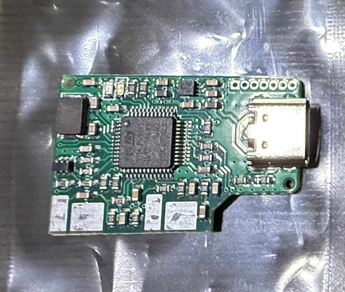
AIOC board from Steve, KM9G.

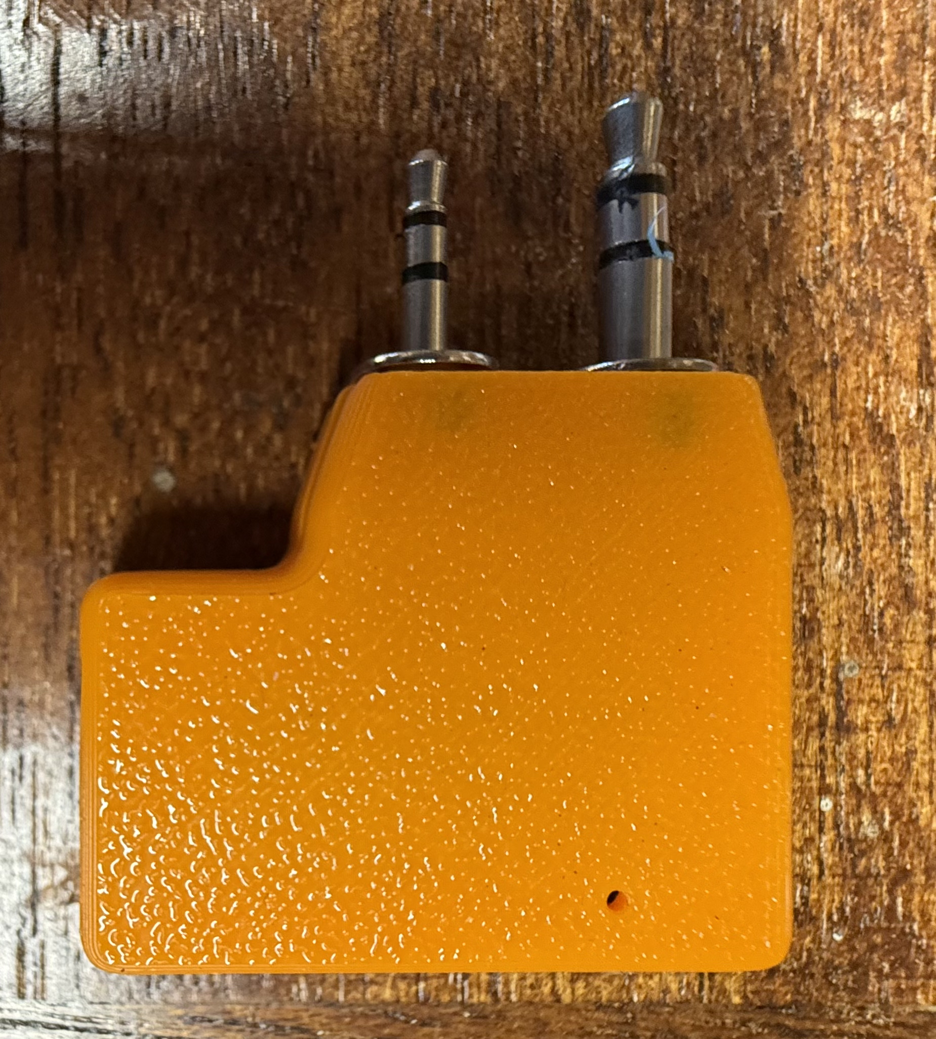
The AIOC board really is tiny but, beautifully put together. The four large solder pads on the top and more on the underside are positioned such that the TRS plug solder lugs line up perfectly for soldering. Attempting to do this by hand would be impossible as it’s critical that the spacing between the two connectors matches that of the spacing of the sockets on the radio.

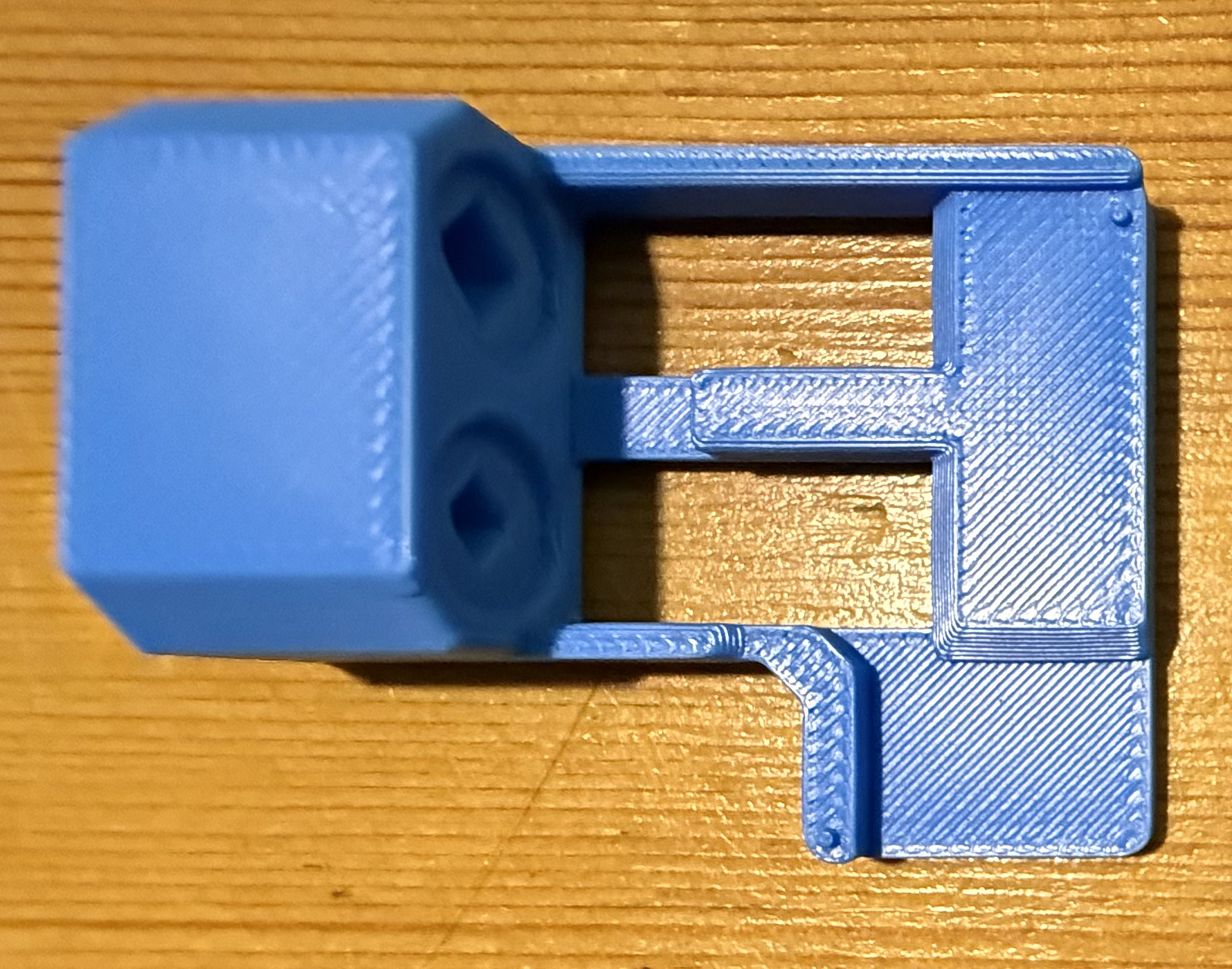
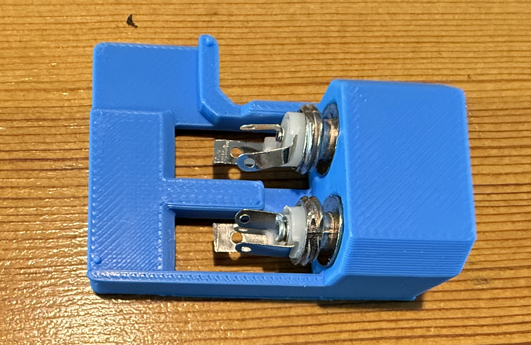
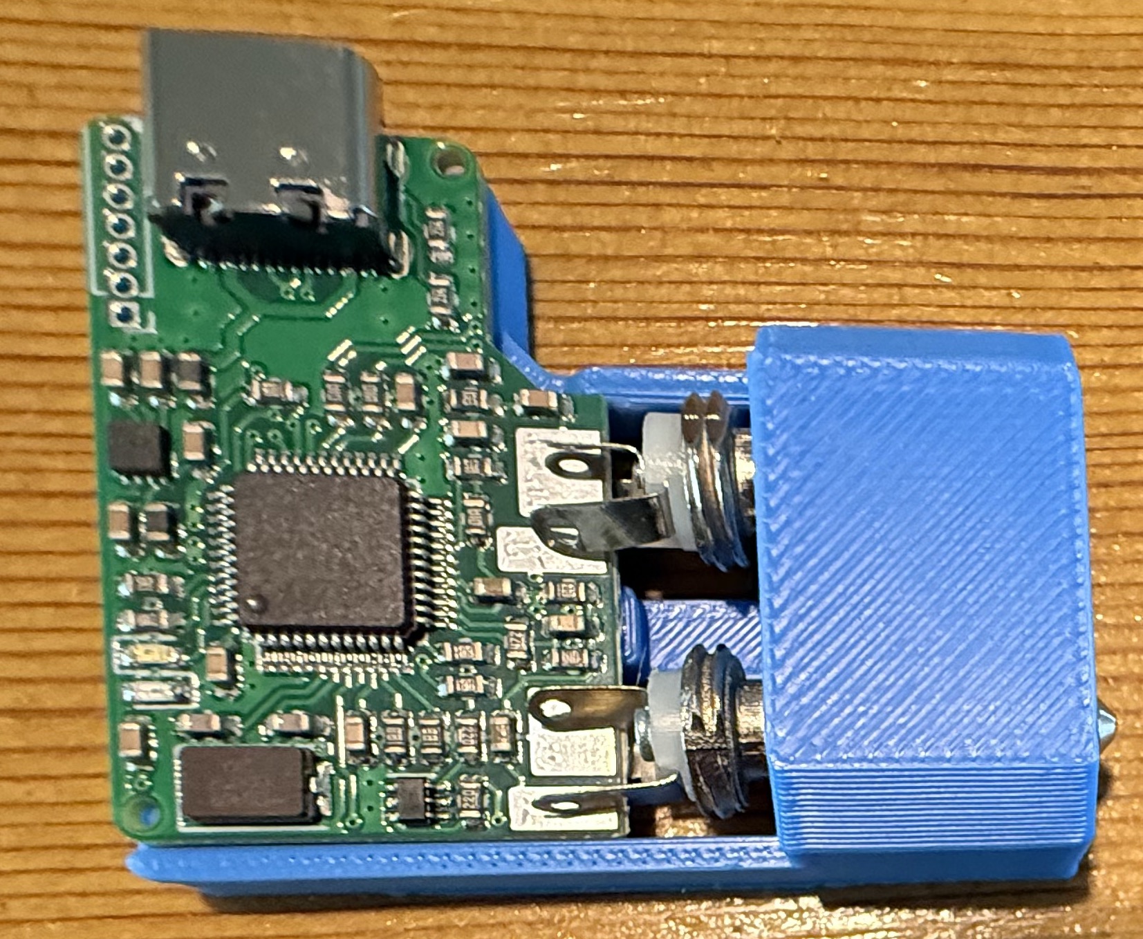
AIOC Solder Jig.
AIOC Solder Jig.

Searching online I found a very handy soldering jig on Github that enables you to hold both the TRS connectors and AIOC board in the perfect position for soldering.

Downloading the .STL file I quickly printed off a solder jig on my Bambu Lab A1 Combo 3D printer and fitted the components into place ready for soldering.

Everything fitted rather snugly into the jig and I soon had the board and connectors soldered together. Test fitting to my Retevis RT85 I found the TRS plugs lined up perfectly and it slid into the sockets with ease.

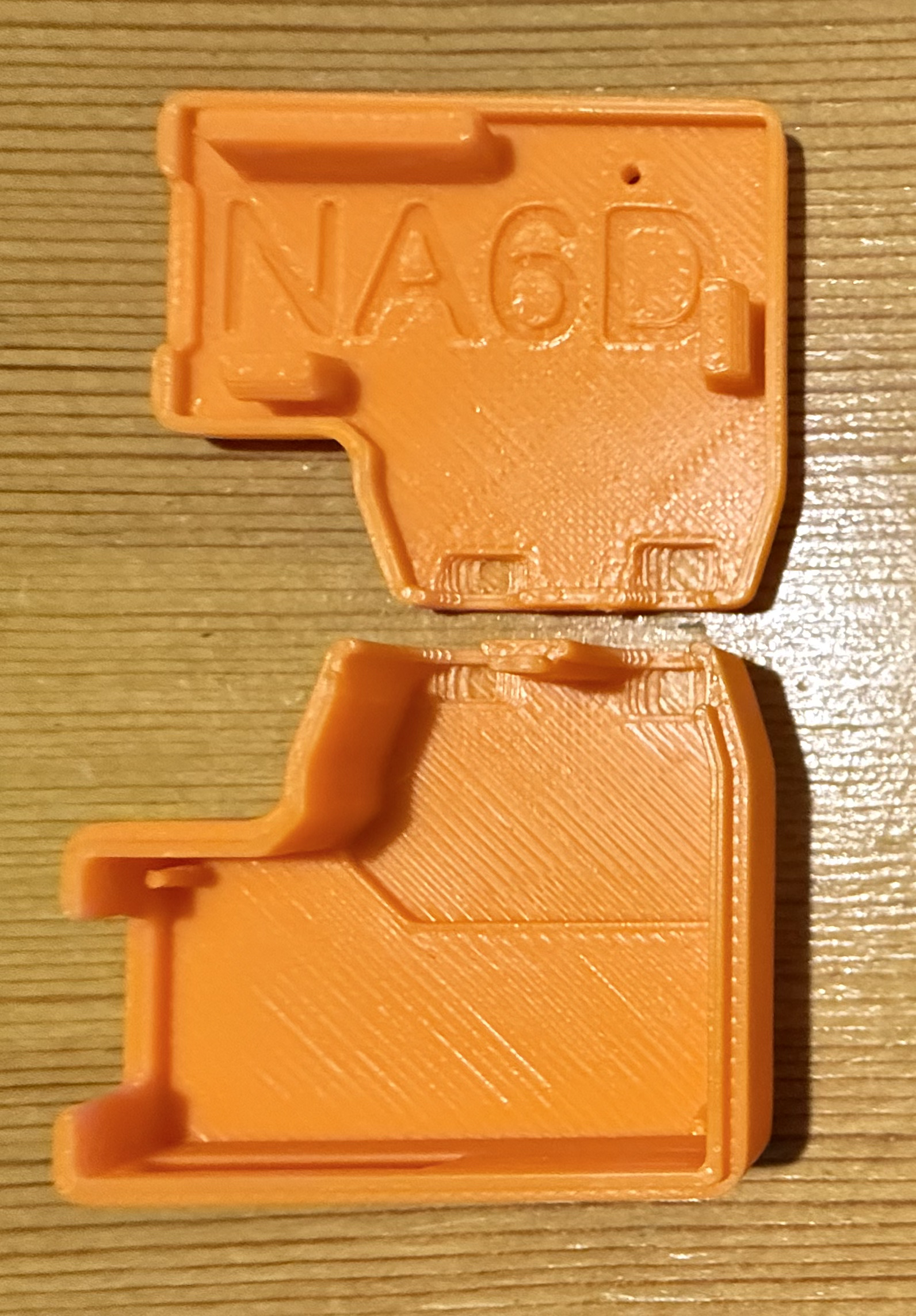
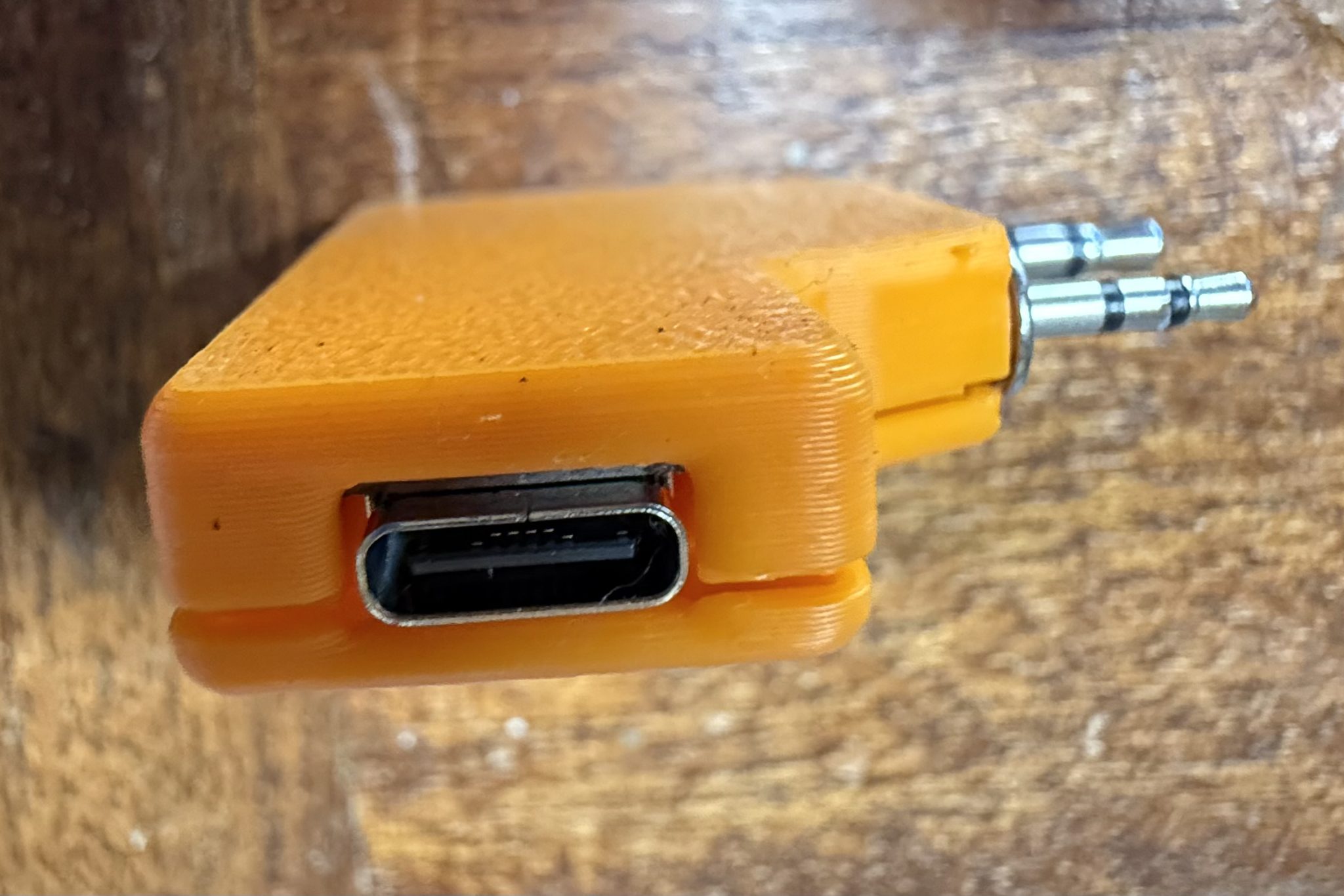
I then thought about designing a case for the AIOC board so that the bare circuit was nicely protected but, quickly searched online and found that NA6D has already designed a case and made the .STL available publicly for download on Printable.com. I quickly grabbed a copy of the file and punted it off to my 3D printer to get to work on.

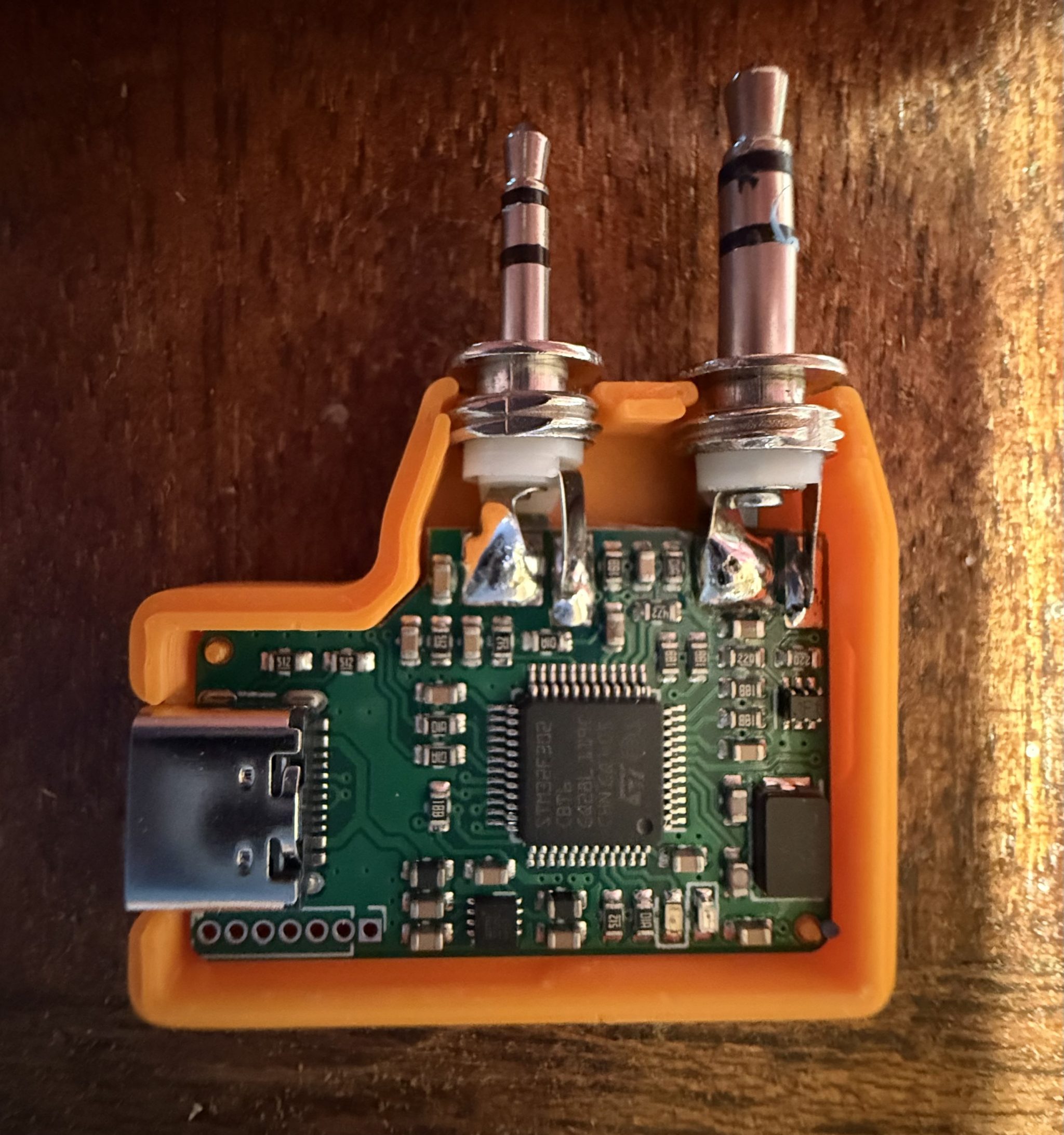
3D print NA6D AIOC case.

Once the print was complete I fitted the AIOC board and snapped it together ready for testing.

Now that the AIOC was production ready I moved on to getting the latest version of AllStarLink onto my RaspberryPi 4 that I had taken out of my RadioBerry based shortwave receiver that I am going to upgrade to a Hermes Lite 2 in a later project. The RaspberryPi 4 is perfect for AllStarLink 3, a 64bit app and operating system.

Using the RaspberryPi Imager I pulled the image down onto an SD card and slipped it into my Pi4. ( Instructions on how to do this are on the AllStarLink website here )

Booting the Pi4 for the first time I found that it went through a number of reboot and configuration cycles before it was ready for use.

Once ready I went through all the normal configuration of the Pi4 namely, static IP assignment, timezone config, security, port forwarding etc etc.

Having configured an AllStarLink node for myself and only just a few days ago for another HAM I was pretty familiar with the setup. Wanting to make sure there were no “gotcha’s” I also watched a couple of KM9G’s videos on Youtube to make sure I wasn’t missing anything.

Using the asl-menu command line app as user root I set about configuring Asterisk to work with the AIOC board. Much to my frustration I could not get Asterisk to recognise the AIOC board as an available sound device. I checked and double checked all the settings ensuring that I had selected “AIOC” in the available devices menu but found that Asterisk constantly errored saying it could not find the selected audio device. This went on for a whole day without success and so, I decided to put it to one side and come back to it later, a method I found that often worked.

A couple of days later I revisited the problem and had decided to take a different approach. Rather than continue going through the asl-menu app I decided to drop down to a lower level and go through the asterisk config files in the /etc/asterisk directory.

It wasn’t long before I found a file called res_usbradio.conf. Inside this file was the config for the AIOC board however, it was all commented out which meant it was disabled.

I’m guessing here but, I imagine this is what should get enabled when selecting AIOC in the available devices menu in the asl-menu command line app but, for some reason it doesn’t happen.

[general]
;usb_devices = 1209:7388    ;comma delimited list of usb
                            ;descriptors to allow.
                            ;format vvvv:pppp in hexadecimal
                            ;vvvv=vendor id, pppp=product id
                            ;
                            ;1209:7388 = AIOC (all in one cable)

Above is the disabled configuration which is easily edited to enable the AIOC device as shown below.

[general]
usb_devices = 1209:7388    ;comma delimited list of usb
                            ;descriptors to allow.
                            ;format vvvv:pppp in hexadecimal
                            ;vvvv=vendor id, pppp=product id
                            ;
                            1209:7388 = AIOC (all in one cable)

Once the updated file had been saved and I restarted Asterisk using systemctl the AIOC burst into life and Asterisk recognised it immediately. The Retevis RT85 switched between TX and RX and I was ready to check out the audio.

Setting the volume levels for both RX and TX via the command line tuning app I connected the node to my already existing node. Sure enough the two nodes connected without error and I was able to send and receive audio between them via the AllStarLink net.

Connecting the new node to the parrot I checked the audio levels to ensure it sounded ok and then connected it to the Matrix node where I had a brief chat with Ben, M8TKK.

All that is left to do now is to 3D print a case for the Pi4 so that it isn’t left naked and at risk of being shorted out on conductive surfaces and it’ll be ready for service.

I also plan to build another AllStarLink node using a 4m band handheld and another AIOC board and then will apply for MB7Ixx callsigns for the two new nodes. This will hopefully help to bring some life to the 2m/4m bands locally and introduce HAM’s both to the weekly Matrix Net and HUBNet/FreeStar via AllStarLink.

More soon …

Using Node-Red to build interactive log maps

I’ve not been on the radio much over the last few weeks as I’ve had my head down other radio related rabbit holes.

One of the rabbit holes is a Node-Red project to make my online logs a little more interactive. For sometime now my logs have been displayed on my website as nicely formatted, searchable HTML pages however, they don’t really allow the viewer (myself included) to see the global coverage of all the contacts so, I decided to write a Node-Red flow that would do just that.

M0AWS Interactive Log Flow

The flow itself isn’t too complicated and basically consists of reading in the individual ADIF formatted log files, processing the data and then sending the data in the correct format to the map node for display.

I’ve had to write a few functions to handle the processing of the ADIF formatted data but, these aren’t particularly complex and are fairly easy to understand even if like me, you’re not a Javascript programmer.

The flow is working perfectly however, I’m in the process of reworking the format generic payload function to reduce the amount of code and make it more efficient.

M0AWS SSB / CW / FreeDV Interactive Log World Map
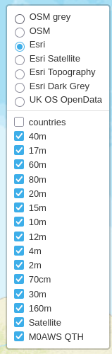
M0AWS Interactive Log Map Layers Menu


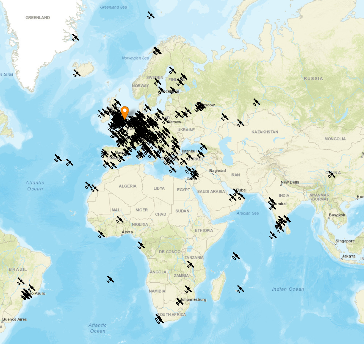
The flow generates two maps, one for voice / CW /Satellite contacts and the other for WSJT-X FT4/8 contacts. Every pin on the map is colour coded by band with satellite contacts being denoted by a satellite icon.

Each pin / icon on the map is clickable and reveals the data of the QSO being displayed.

In the top right-hand corner of the map there is a drop down layer menu that allows the viewer to filter by band thus reducing the number of icons on the screen at any one time.

Seeing the data presented on a map really brings my logs alive. An example of this is that I had no idea I’d worked so many stations in India on the QO-100 Satellite.

The small icons in the pins show a microphone for SSB/FM/FreeDV contacts and a downwards pointing triangle in a box for CW contacts. Sadly I couldn’t find a Morse key icon in the collection available.

M0AWS filtered view of QO-100 Satellite contacts

I only use FT4/8 for testing new antenna designs however, it’s interesting to see the global coverage accomplished with this weak signal mode.

M0AWS WSJT-X FT4/8 Interactive Log World Map

Once I’ve finished rewriting the format generic payload function I will make the flow available for download here so that others can also create an interactive view of their radio logs.

If you want to have a look at the maps and try them out for yourself, they are available under the Logs menu above.

This Node-Red instance is running in a virtual machine (VM) on a 16GB RAM RaspberryPi 5 that is also running a number of other VMs at the same time so, it’s safe to say it’s not heavy on CPU and will run on the older Pi4 as well.

More soon …

Virtual Machines on RaspberryPi 5

RaspberryPi computers are now moving into the realm of being powerful enough to replace the traditional desktop PC. My most recent purchase, a RaspberryPi 500+ is proof of this as it has been my daily desktop PC since it’s arrival.

One of the things I use heavily are virtual machines. They’re great for developing, prototyping and running new services. With the ability to snapshot, rollback and backup in an instant, virtualisation helps to reduce the development and test time for many of the programs and services that I’m playing with.

With RaspberryPi computers now supporting 16GB of RAM and M.2 SSD drives there is no reason for not taking advantage of virtualisation.

To this end I decided to test running some virtualised loads on my new 500+ with the plan to deploy to 16GB Pi5’s with SSD drives in place of more expensive Intel based computers.

On my Intel based machines I use QEMU, KVM and Virt-Manager to manage the multitude of virtual machines (VMs) I have running here. Since this is a solid, high performance platform for running VMs I decided to take the same route on the 500+

Installing the necessary packages is extremely simple, just one simple apt command:

sudo apt install qemu-kvm libvirt-daemon-system libvirt-clients virt-manager bridge-utils

Note: If you’re using Debian 13 (Trixie) then the apt command to use is:

sudo apt install qemu-system-arm libvirt-daemon-system libvirt-clients virt-manager bridge-utils

The qemu-kvm package doesn’t exist in Debian 13 and so you have to replace it with the qemu-system-arm package.

To be able to create and run VMs you need to add yourself to the libvirt and libvirt-qemu groups.

sudo usermod -a -G libvirt your_username
sudo usermod -a -G libvirt-qemu your_username

Of course you can do it the old-fashioned way by editing the /etc/group file and adding your username to each group.

You’ll need to create a bridged ethernet device for the VMs to use to access the ethernet interface on your RaspberryPi.

If like me you don’t use NetworkManager the easiest way to create a bridge is to define it in your /etc/network/interfaces file.

For this example I am using an IP Address of 192.168.0.100, gateway on 192.168.0.1 with a netmask of 255.255.255.0 and DNS nameserver on 192.168.0.5.

The normal entry in the interfaces file would look like this:

# Main ethernet
auto eth0
iface eth0 inet static
address 192.168.0.100
netmask 255.255.255.0
gateway 192.168.0.1
dns-nameservers 192.168.0.5
dns-domain lan.local
dns-search lan.local
#
#

To create a bridge this entry needs to change to:

# Main ethernet
# Setup Bridge called br1 on eth0
allow-hotplug eth0
iface eth0 inet manual
auto br1
iface br1 inet static
address 192.168.0.100
network 192.168.0.0
netmask 255.255.255.0
broadcast 192.168.0.255
gateway 192.168.0.1
dns-nameservers 192.168.0.5
bridge_ports eth0
bridge_stp off
#
#

Once this is done reboot your RaspberryPi and check you have access to your local LAN and of course the internet. You will now also inherit the two new groups that you added yourself to above.

Note: If you are using NetworkManager open the network settings app and create a bridge on eth0. You can also use the nmtui copmmandline app if you prefer.

At this point you’re ready to create your first virtual machine.

It’s important to have an arm64 version of Linux in ISO format that you can use to install into your VM. My preferred distro is Debian and so I downloaded the Debian 13 Arm64 netinst ISO from the debian.org website.

From the main menu start “Virtual machine Manager” or on the commandline type:

virt-manager
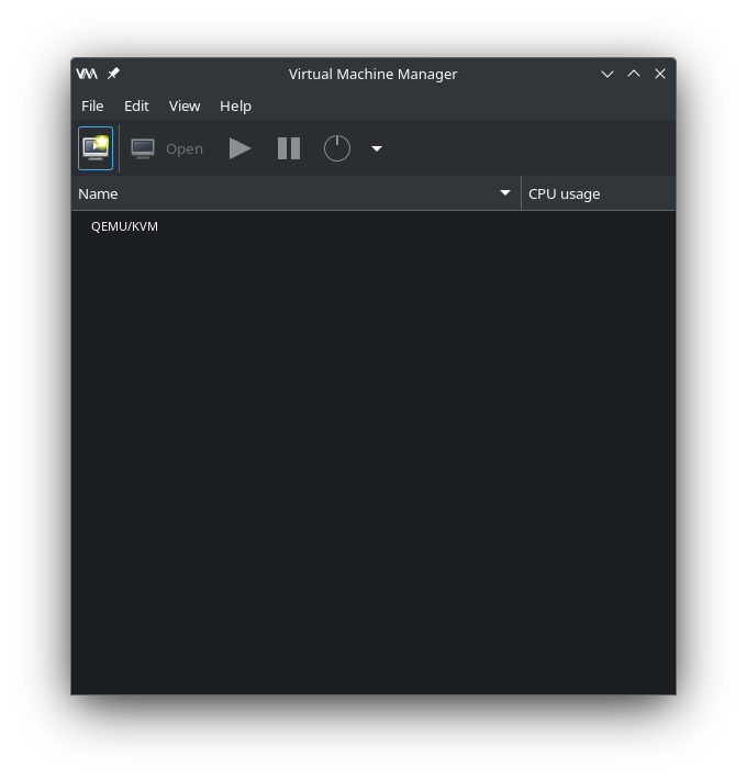
QEMU Virtual Machine Manager

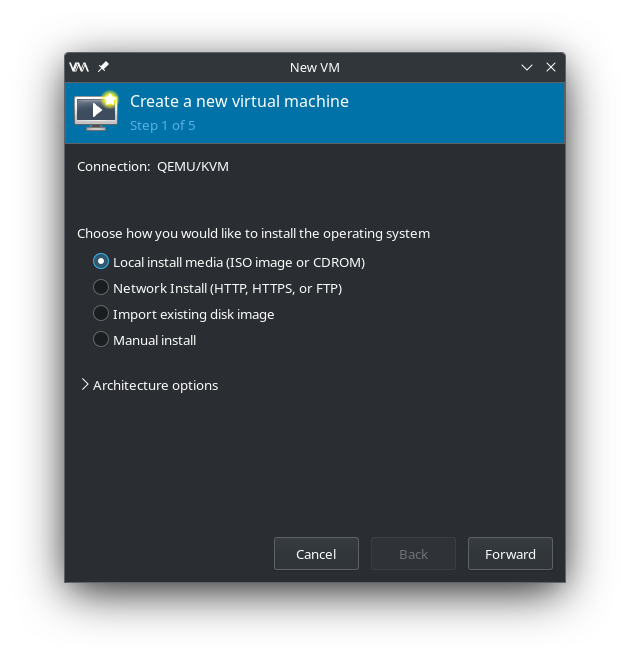
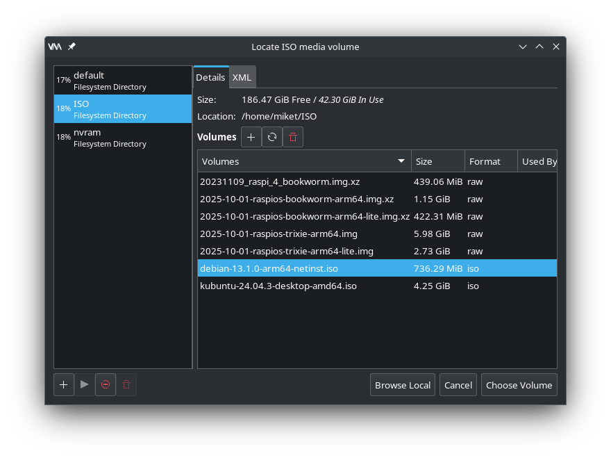
Click the Create new VM button and then navigate to where you saved your ISO file and select it as the installation media.

Virtual Machine Manager - Local install media
Virtual Machine Manager – Local install media
Virtual Machine Manager - Select ISO file
Virtual Machine Manager – Select ISO file

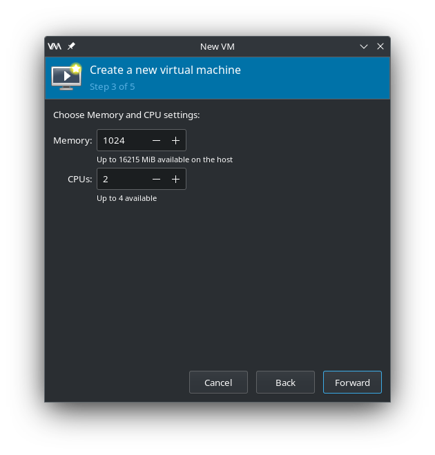
Once you’ve chosen your ISO you’ll need to configure the actual VM. Start by setting the amount of RAM and number of virtual CPUs you want the VM to have.

Virtual Machine Manager - Configure RAM and CPU
Virtual Machine Manager – Configure RAM and CPU

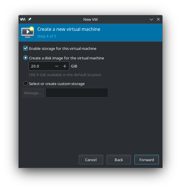
Next set the size of the virtual disk that the VM will use.

Virtual Machine Manager - Create virtual disk
Virtual Machine Manager – Create virtual disk

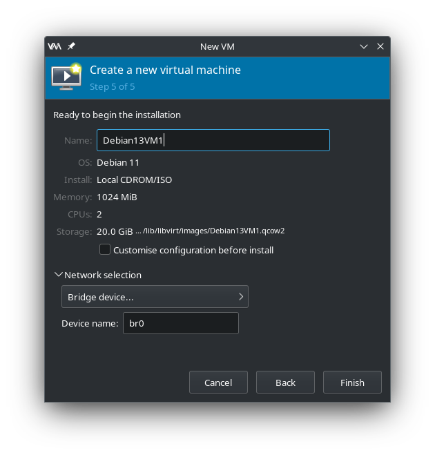
Finally, give the VM a name and set its network device to br0 as created above. Click finish and your VM will boot.

Virtual Machine Manager - Name VM and select bridge interface
Virtual Machine Manager – Name VM and select bridge interface

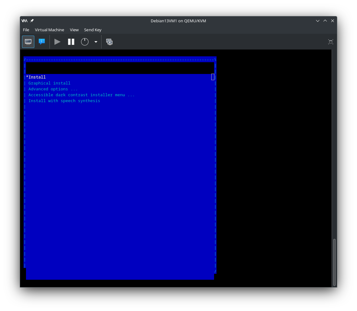
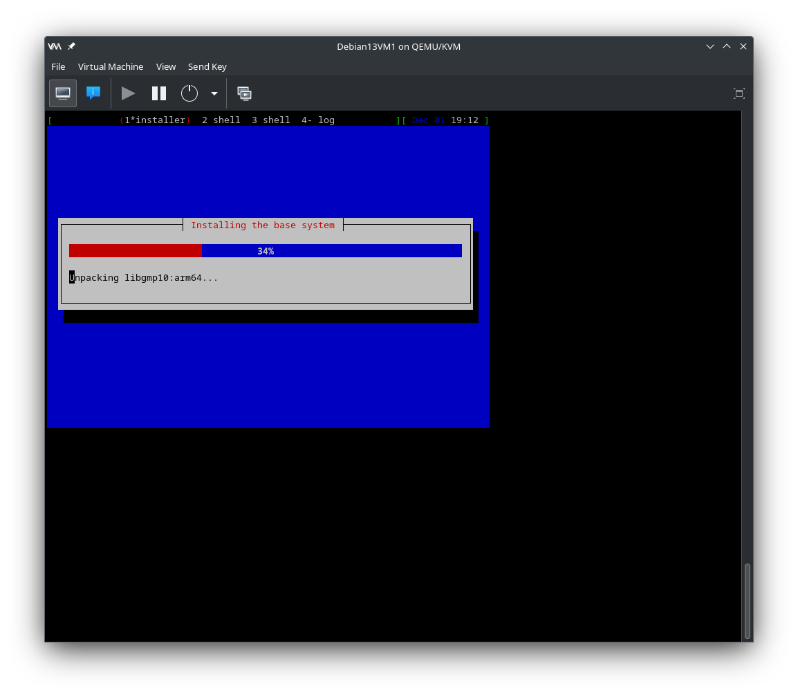
Now it’s just a case of going through the standard Debian install process to build your Debian VM.

Virtual Machine Manager - Boot ISO
Virtual Machine Manager – Boot ISO
Virtual machine Manager - Running standard Debian install
Virtual machine Manager – Running standard Debian install

Once the installation is complete and the VM has rebooted you will have a functional Debian computer ready to use for whatever you like, just like a physical PC but, in virtual form. You’ll find that the VM runs as fast as the actual physical machine thanks to the kernel based virtualisation.

Virtual Machine Manager - Running VM
Virtual Machine Manager – Running VM

For more information on Virtual Machine Manager take a look at the Ubuntu Server documentation.

More soon …