Meshtastic is a relatively new thing in the internet of things (IOT) world and is gaining traction in the U.K. at the moment.
So what is Meshtastic?
Meshtastic is an open source, off-grid, decentralised mesh network built to run on affordable, low-power devices on the 868Mhz industrial, scientific, and medical (ISM) band. (Some devices can also run on the 433Mhz 70cm HAM band.)
The ISM band is licence free but, has limits on the RF power levels that can be used. The one plus over the HAM bands is that you can legally transfer encrypted messages over the ISM band making it secure.
The best way to think of Meshtastic is a radio version of the online decentralised Matrix chat system but, without the large server requirements and ever growing database!
Heltec ESP32 v3 Wifi, Bluetooth and 868Mhz device for Meshtastic
There are quite a few Meshtastic compatible devices on the market today with many costing around the £20 mark whilst others like the LillyGo T-Echo costing over £100 in the U.K. even though they are less than half the price in the USA.
Since I’m just starting out on my Meshtastic adventure I thought I’d start with a pair of Heltec ESP32 v3 devices that are normally readily available on Amazon but, due to the current push to build a U.K. wide mesh, they are currently out of stock pretty much everywhere.
Loading the Meshtastic firmware onto the devices is fairly straight forward and can be done using the web installer via either the Edge or Chromium web browsers. (Note: If using Windows O/S you will need to install some drivers from the Meshtastic website to be able to communicate with the devices)
Having neither of the two browsers and being a Linux command line junkie I decided to use the Python programme to load the firmware onto the two devices. It’s worth noting that you don’t need any drivers to be able to communicate with the devices if you’re using either Debian or one of the many Ubuntu flavours of Linux O/S.
Using the Python command line program sounds like a more complicated approach but, in reality it’s super simple, extremely reliable, quick and if like me you use a Linux PC in the radio shack then you most likely already have most of what you need to get the job done. Just follow the simple steps as laid out on the Meshtastic web site and you’ll have the firmware loaded in no time at all.
Installing the Meshtastic firmware onto my Heltec ESP32 v3 using the Python command line tool
The firmware takes less than a minute to copy across to the Heltec device and is automatically rebooted ready for configuration once the transfer has completed.
It is possible to configure the device via the command line tool however, since there is a nice GUI app for both Apple iOS and Android devices I decided to install the Meshtastic app on my iPad and connect to the device via Bluetooth to configure it.
Once you’ve got the Meshtastic app installed on your device and have connected via Bluetooth you’ll be ready to start configuring the device to join the mesh. The first thing you want to do is set the region. This is different in each country but, in the UK we use the EU_868 region settings. This will set the device to use the 868Mhz ISM band which is the band being used to build the U.K. wide mesh.
View of the Meshtastic app on iOS showing the configuration options for the Heltec ESP32 v3
There is a multitude of configuration options within the app which I will go into in greater detail in a series of articles at a later date.
Heltec ESP32 v3 running Meshtastic Firmware
For those of you that, like me aren’t near any other nodes you can connect the devices to the internet and use the Meshtastic MQTT server to communicate with other nodes. This of course isn’t off-grid but, it will get you started until the mesh grows into your local area at which point your device will automatically start communicating with the other nodes over radio.
Meshtastic MQTT connectivity
Once you are connected to either the MQTT server or other nodes via radio you will see the other node details appear in the Meshtastic app. It’s interesting to look at the information and see signal strengths and traffic levels etc for each node.
View of the Meshtastic app on iOS showing Nodes in the Mesh and Device Metrics for the M0AWS-1 Node
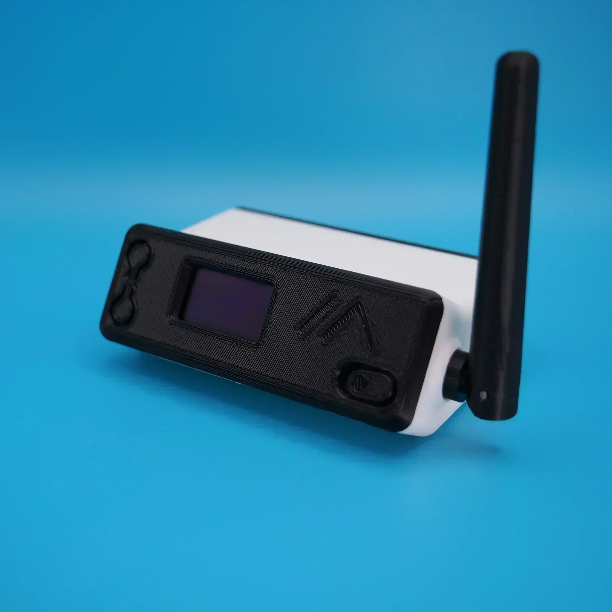
There are a multitude of cases available for the Heltec v3 devices, especially if you have access to a 3D printer. One of the nicest cases I have seen is the Bender from IKB3D (I know, it’s a strange name!) but, it really is a super little case for the Heltec series of devices.
Bender case for Heltec ESP32 v3 devices
You can either buy the 3D print files for £8.99 and print it yourself or just order a pre-printed and assembled case directly from the website although, due to demand there is a long lead time currently.
I’ve been gradually building my QO-100 ground station over the last few months and have had the receive path working for some time now. One of the things I really miss with the Funcube Dongle Pro+ (FCD) SDR is a real VFO knob for changing frequency.
My QO-100 Node Red dashboard is configured so that I can have the FCD track the uplink frequency from the IC-705 but, sometimes I use the FCD without the IC-705 in the shack and so a physical VFO would be handy.
Many years ago when I lived in France (F5VKM) I had a Flexradio Flex-3000 SDR, a great radio in it’s time and one that gave me many hours of enjoyment. One addition I bought for that station was a Griffin Technology Powermate VFO knob. It worked extremely well with the PowerSDR software for the Flex-3000 and I used it for many years.
Many years later I’m back in the UK and much of my equipment is packed away in the attic, including the Griffin Technology Powermate VFO.
I decided to dig it out and see if I could get it working with GQRX SDR software. Sadly I couldn’t get it working with GQRX however, I did find a way of getting it working with Node Red and thus could add it to my QO-100 Node Red Dashboard and then control GQRX with it via a simple Node Red flow.
Griffin Technology Powermate VFO
Plugging the Powermate VFO into my Kubuntu PC it wasn’t immediately recognised by the Linux O/S. After a little searching I found the driver on Github. I added the PPA to my aptitude sources and installed the driver using apt.
Once installed the default config for the Powermate device is to control the default audio device volume. To make the device available for use as a VFO knob you need to change the configuration so that the default setting is disabled. To do this is relatively easy, just edit the config file using your favourite command line editor (Vi/Vim in my case) and add the following entry.
vi /etc/powermate.toml

# Entry to control HDMI volume with Powermate
#sink_name = "alsa_output.pci-0000_01_00.1.hdmi-stereo"

# Set powermate not to work with volume control
sink_name = ""
As shown above, comment out the default “sink_name” entry (Yours may be different depending on audio device in your PC) and add in the Powermate “sink_name” entry that effectively assigns it to nothing.
Once this is done, save the file and exit your editor and then reboot the PC.
Next you’ll need to install a small program called evtest.
sudo apt install evtest
To check the evtest program has installed correctly, plugin your Powermate VFO to any available USB port and run the following command in a terminal.
evtest /dev/input/powermate
Turning the Powermate knob you should see output on the screen showing the input from the device. You should also see BTN events for each press of the Powermate device.
Input driver version is 1.0.1
Input device ID: bus 0x3 vendor 0x77d product 0x410 version 0x400
Input device name: "Griffin PowerMate"
Supported events:
  Event type 0 (EV_SYN)
  Event type 1 (EV_KEY)
    Event code 256 (BTN_0)
  Event type 2 (EV_REL)
    Event code 7 (REL_DIAL)
  Event type 4 (EV_MSC)
    Event code 1 (MSC_PULSELED)
Properties:
Testing ... (interrupt to exit)
Event: time 1685816662.086666, type 2 (EV_REL), code 7 (REL_DIAL), value -1
Event: time 1685816662.086666, -------------- SYN_REPORT ------------
Event: time 1685816662.318638, type 2 (EV_REL), code 7 (REL_DIAL), value -1
Event: time 1685816662.318638, -------------- SYN_REPORT ------------
Event: time 1685816662.574615, type 2 (EV_REL), code 7 (REL_DIAL), value -1
Event: time 1685816662.574615, -------------- SYN_REPORT ------------
Event: time 1685816663.670461, type 2 (EV_REL), code 7 (REL_DIAL), value 1
Event: time 1685816663.670461, -------------- SYN_REPORT ------------
Event: time 1685816664.030421, type 2 (EV_REL), code 7 (REL_DIAL), value 1
Event: time 1685816664.030421, -------------- SYN_REPORT ------------
Event: time 1685816664.334389, type 2 (EV_REL), code 7 (REL_DIAL), value 1
Event: time 1685816664.334389, -------------- SYN_REPORT ------------
Event: time 1685816665.334255, type 1 (EV_KEY), code 256 (BTN_0), value 1
Event: time 1685816665.334255, -------------- SYN_REPORT ------------
Event: time 1685816665.558230, type 1 (EV_KEY), code 256 (BTN_0), value 0
Event: time 1685816665.558230, -------------- SYN_REPORT ------------
Event: time 1685816666.030161, type 1 (EV_KEY), code 256 (BTN_0), value 1
Event: time 1685816666.030161, -------------- SYN_REPORT ------------
Event: time 1685816666.182151, type 1 (EV_KEY), code 256 (BTN_0), value 0
Event: time 1685816666.182151, -------------- SYN_REPORT ------------
At this point you’re ready to stop evtest (CTRL-C) and then create the following little BASH shell script that Node Red will run to collect the O/P from the Powermate USB device.
#!/bin/bash

###############################################
# Griffin Technology Powermate control script #
# for Node Red.                               #
#                                             #
# 04/06/23 - M0AWS - v0.1                     #
#                                             #
###############################################

VAL="1"
echo "STEP-1Hz"

/usr/bin/evtest /dev/input/powermate | while read LINE
do
   case $LINE in

      *"(REL_DIAL), value 1") echo "$VAL"
           ;;

      *"(REL_DIAL), value -1") echo "-$VAL"
           ;;

      *"(BTN_0), value 1") case $VAL in

                              "1") VAL="10"
                                   echo "STEP-10Hz"
                                      ;;

                             "10") VAL="100"
                                   echo "STEP-100Hz"
                                      ;;

                             "100") VAL="1000"
                                    echo "STEP-1Khz"
                                       ;;

                             "1000") VAL="10000"
                                     echo "STEP-10Khz"
                                         ;;

                             "10000") VAL="1"
                                       echo "STEP-1Hz"
                                          ;;
                              esac
                                 ;;
        esac
done
Once the BASH script is copied and pasted into a file called powermate.sh you need to make it executable by using the following command.
chmod 700 ./powermate.sh
If you now run the shell script in a terminal you’ll see a similar output to that shown below from the device when used.
As you can see above the shell script outputs a positive or negative number for VFO tuning and changes the VFO step size each time the Powermate is depressed.
Getting this output from the BASH shell script into Node Red is really simple to achieve using just 3 or 4 nodes.
In the Node Red development UI create the following nodes.
Griffin Powermate Node Red Nodes
The first node in the flow is a simple inject node, here I called it trigger. This sends a timestamp into the next node in the flow at startup to set the flow running.
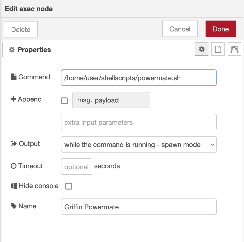
The Griffin Powermate node is a simple exec node that runs the script we created above.
M0AWS Powermate exec node
Configure the node as shown above and connect it to the inject node that’s used as a trigger. Note: Change “user” in the Command field shown above to that of your username on your Linux PC)
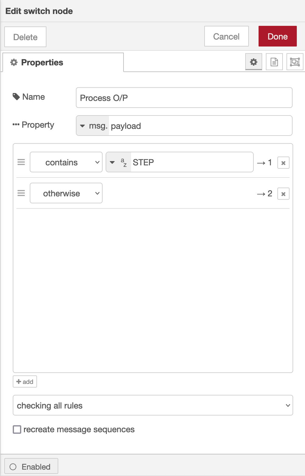
Once done create the third node in the flow, a simple switch node and configure as shown below.
Switch Node for Powermate
The switch node has two outputs, the top one is a text output that is fed into a text field to show the current step size of the Powermate device and the lower output is the numeric output that must be fed into your VFO control flow so that the VFO value is incremented/decremented by the amount output by the Powermate device.
I’ve found the Griffin Technology Powermate USB device works extremely well with Node Red and GQRX that I use for controlling the FCD SDR radio and it’s now part of my QO-100 ground station build.
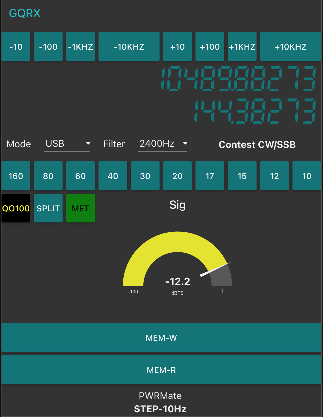
M0AWS QO-100 Dashboard with Powermate Step Display at bottom
As shown above you can see the Powermate Step size at the bottom of the dashboard, this text changes each time the Powermate device is depressed and will set a step size of 1Hz, 10Hz, 100Hz, 1Khz, 10Khz in a round-robin fashion.
The next stage of the build is the 2.4Ghz transmit path. I now have all the necessary hardware and so this part of the build can finally commence.
Since getting my Icom IC-705 I’ve had problems with computer noise causing interference when connected via USB. I solved the problem mostly by winding both the USB and coax cables around 240-31 ferrite toroids. This resolved the problem nicely on all HF bands except 10m. With further investigation I realised that the 240-31 ferrite toroid doesn’t provide much choking resistance at 28mhz and so a 240-43 would be better for the higher bands. This would mean I’d need a longer USB cable and coax to the AH-705 so that there was enough cable to wind around two ferrite toroids to cover all the HF bands.
Whilst this will almost certainly provide a complete solution to the problem there is of course another way around this issue. The IC-705 is a rare beast in that it has wifi capability built in. The wifi on the IC-705 is capable of operating in one of two different modes, Access Point (AP) and Station, a host on an existing wifi network.
Since I connected my IC-705 to my in-shack wifi I am using the radio in station mode for connectivity via wifi. By connecting it this way my MacBook Pro will also have access to the internet at the same time as connecting to the radio giving me the best of both worlds.
You can of course put the radio into AP mode and connect your computer directly to it via wifi however, you won’t have any internet access from the computer as it will be connected directly to the radio. This is how it will be used when in the field for portable operations unless you have a portable 3/4/5g wifi router.
Getting the radio connected to my shack wifi was easy, just go into the IC-705 menus, switch the WLAN on, pick the SSID of my wifi router and enter the password, the radio connects immediately. You will also need to switch on the network control option and also set up a user and password that is used when connecting to the radio from your computer. Refer to the IC-705 manual on how to do this if you haven’t done it already.
To be able to use the radio wirelessly from any Apple Mac computer you will need 2 applications, WFview and Blackhole. Both of these applications are Opensource Software, I’m a huge fan of Opensource Software and have over the years been involved in a number of opensource projects.
I’m fully aware that there is an application called SDR Control available on the Apple App Store for around £90.00 that can be used instead to connect to the IC-705 wirelessly however, I prefer to use Opensource software where possible.
Before proceeding with the instructions below make sure you have an up to date backup of your system. This installation and configuration shouldn’t cause any issues at all, it worked fine on my MacBook Pro but, it’s always best to backup before you install more complex software like this.
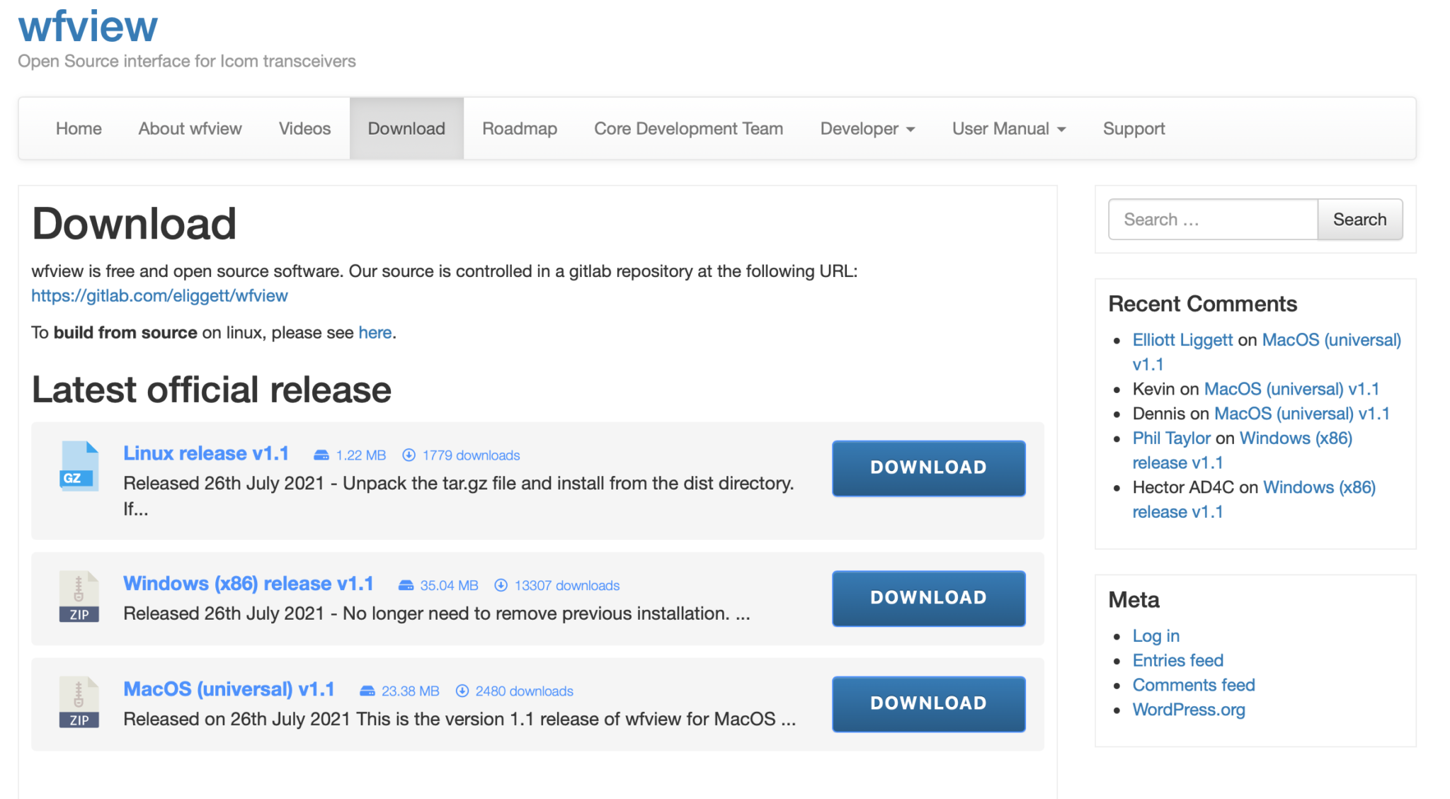
First you need to download WFView from the Download page, make sure to download the MacOS Universal package which was v1.1 at the time writing this article. Do **not** install WFView yet, the sequence of installation is important!
WFView Download page showing the MacOS (Universal) Package v1.1
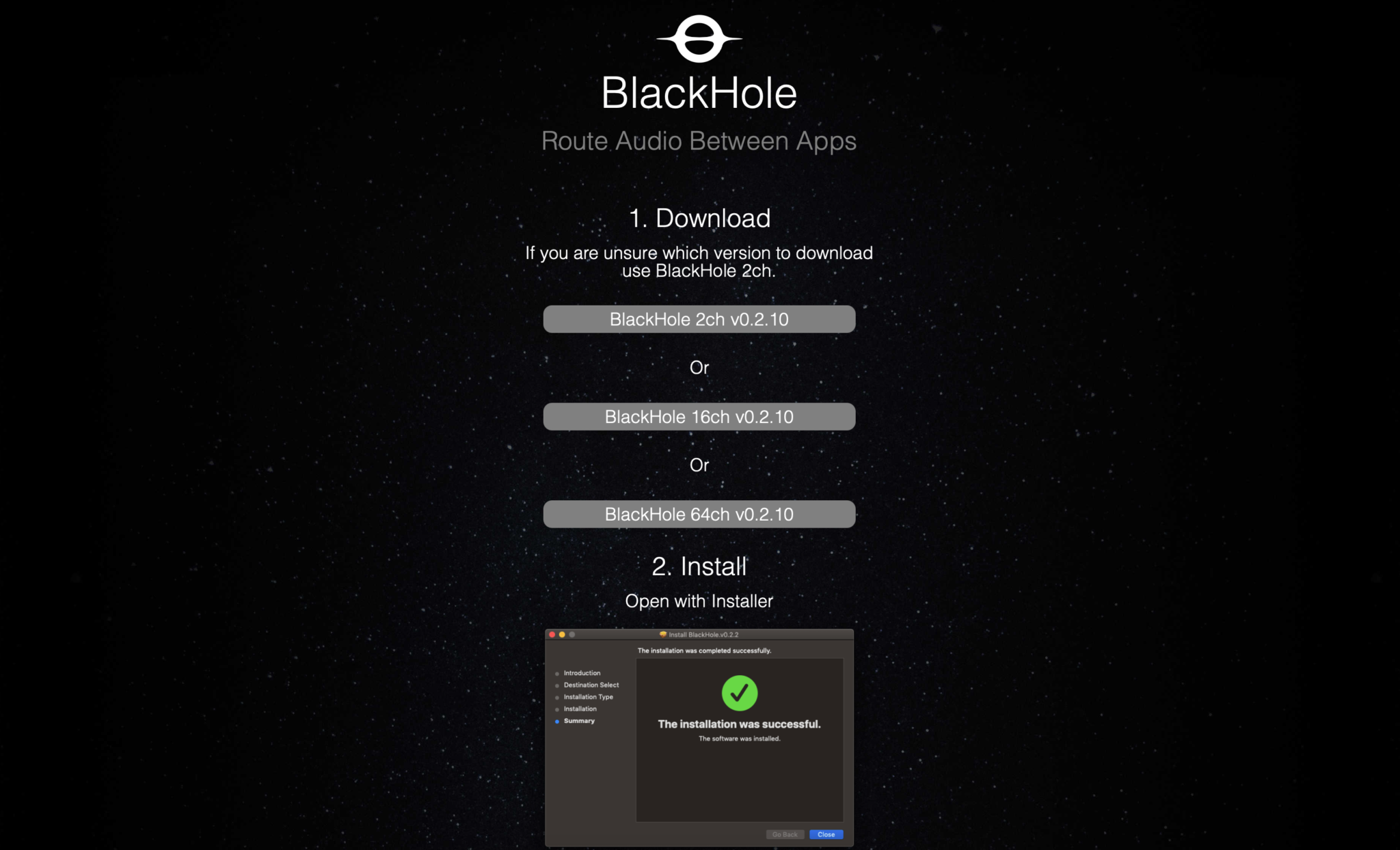
Next download the Blackhole Virtual Audio Cable application from the download page. You will need to enter an email address and your name to be able to download the application. It’s not clear how much email/spam will be sent to you but, you will need to get at least one email to obtain the download link with the authorisation code in it.
Once you’ve entered the information and submitted it you will get an email with a URL enclosed, click the URL and goto the download page. On the page there are 3 options available for download, select the “Blackhole 2 Ch” option only. At the time of writing this v0.2.10 was the current version available.
Blackhole Download page showing the 3 options available
Once downloaded you need to install the Blackhole application first as it will create the necessary virtual audio cable for WFView to use to provide sound to WSJT-X and other digital mode applications. Installation is simple and follows the normal MacOS installation process. Double click the installation package and follow the prompts accordingly.
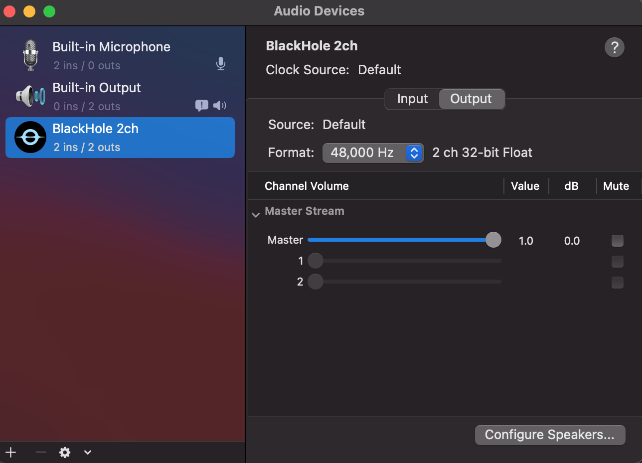
Once installed reboot your Apple computer to make sure it starts up OK with the new kernel module installed. When your system comes back up, login and open the “Audio Midi Setup” application. (The Midi app is in Applications >> Utilities)
Once the application opens you should see that you have a new audio device called “Blackhole 2ch”. On both the Input and Output tabs set the format to 48,000Hz. This setting will get the best results when using applications like WSJT-X for FT4/8 digital modes.
Apple Audio Midi Setup showing 48,000Hz selected
Leave everything else as default setting in the Audio Midi App, nothing else needs changing. Leave the Master volume at the default max as levels are controlled from the other apps.
Once you’ve set the 48,000Hz on the two tabs quit the audio midi app as it’s no longer required.
Next you need to copy the WFView app that you downloaded into the Applications folder on your Mac. Once in the applications folder you can create a shortcut to it on the dock by dragging and dropping the app icon onto your dock bar.
Next goto your IC-705 and go into the WLAN settings and make a note of the IP Address assigned to the radio from your wifi router. You will need this IP Address later.
At this point you are half way to having wireless control of your IC-705.
Start the WFView application and goto the settings tab.
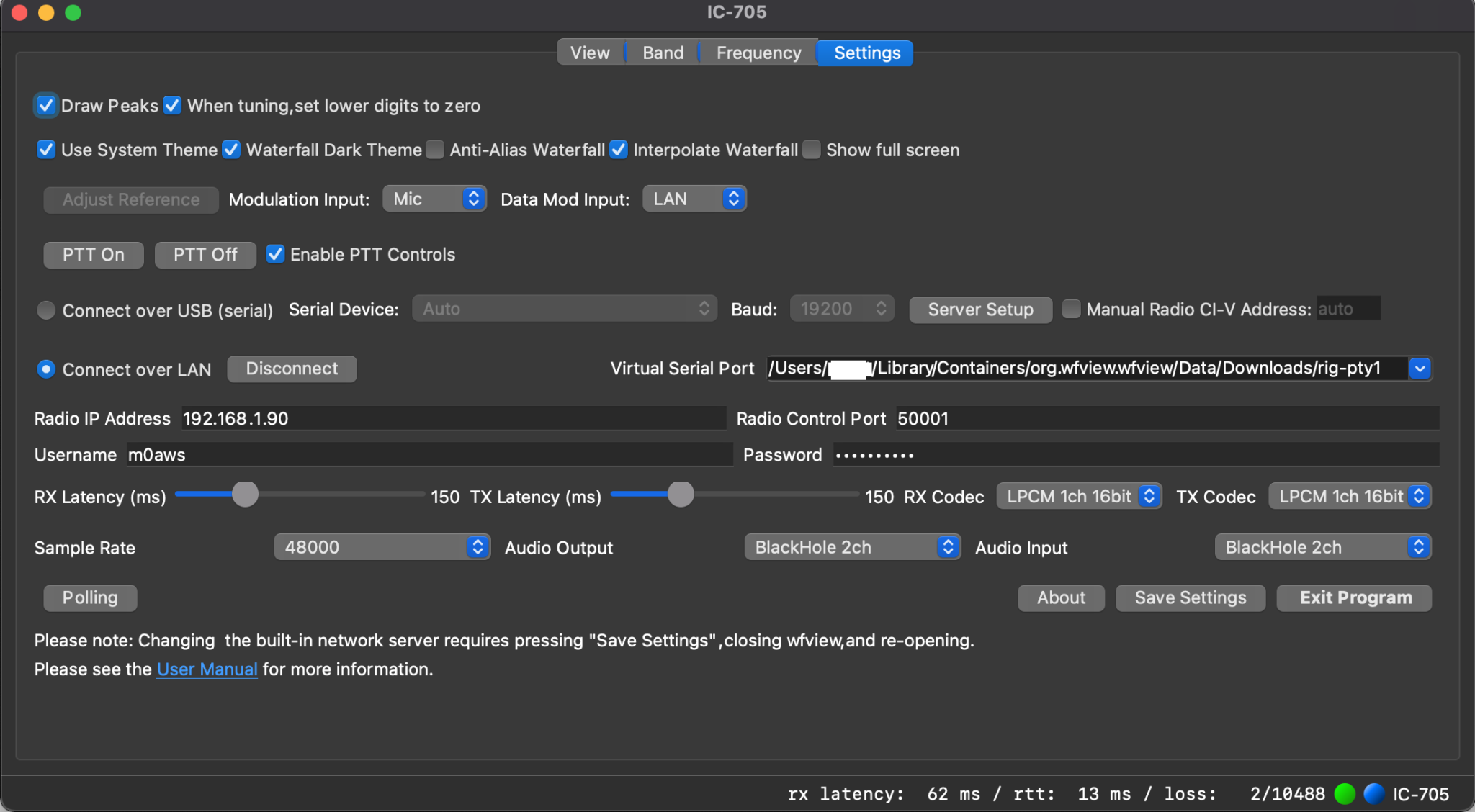
The following settings need to be made:
1: Set Data Mod Input to LAN
2: Click the Connect Over LAN radio button.
3:Enter the IP Address from your IC-705 into the Radio IP Address field.
4: Make sure Radio Control Port is set to 50001
5: Enter the Username you configured on your IC-705 into the Username field
6: Enter the Password you configured on your IC-705 into the Password Field
7: Set Sample Rate to 48000
8:Set Audio Output and Input fields to BlackHole 2ch
9: Select the first option available in the Virtual Serial Port field. This should be as shown below:
Leave all other settings as default and click Save Settings and then Exit Program.
You must exit the application in order to restart it with all the new settings.
WFView Settings tab showing all the necessary settings whilst connected to the radio
Start the WFView application again and goto the Settings tab. Click on the Connect Button.
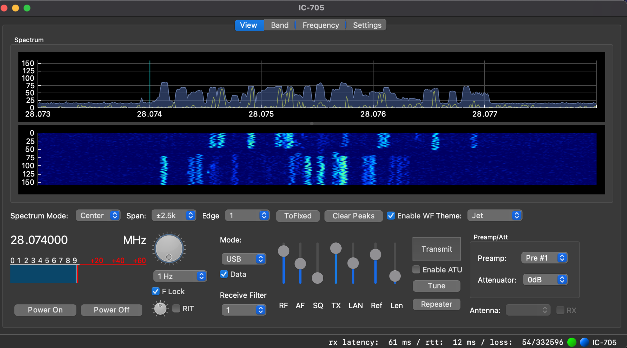
Once it has connected to the radio you will see the RX Latency details etc on the bottom right of the window. Click on the View tab and you should now have an active waterfall.
At this point you have full control of your IC-705 wirelessly. Have a play with the application and get familiar with it.
Fully operational WFView connected to my IC-705 receiving FT8 on 10m
Once I had WFView operational I set about getting WSJT-X connected to the radio wirelessly. This is actually really simple to do and just needs a couple of changes to the settings to make it work.
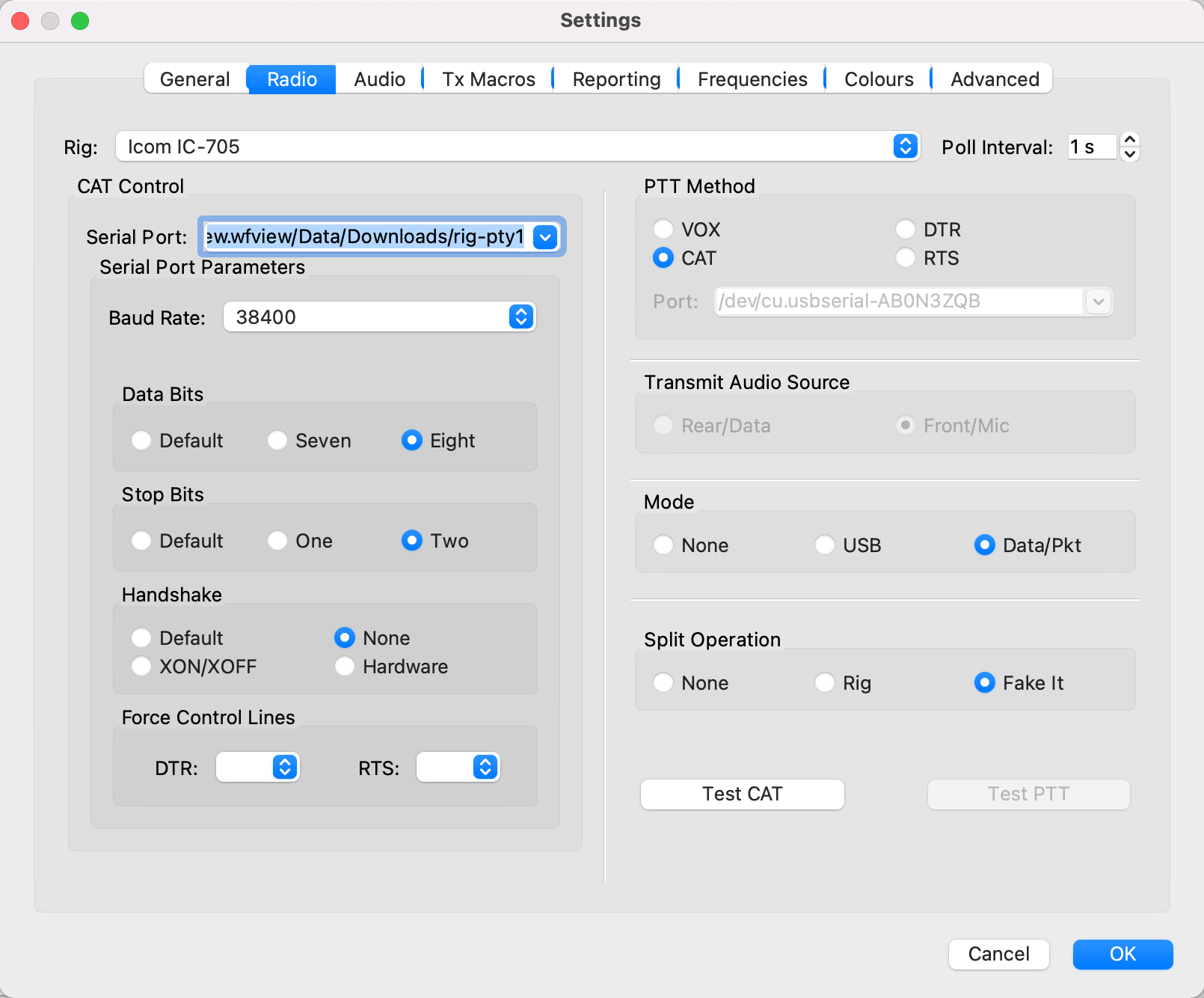
Start up the WSJT-X application and goto the Radio Settings tab. On this page you need to set the radio to IC-705, serial port to that shown below (Also shown in point 9 in the WFView section above) and Baud Rate to 38400.
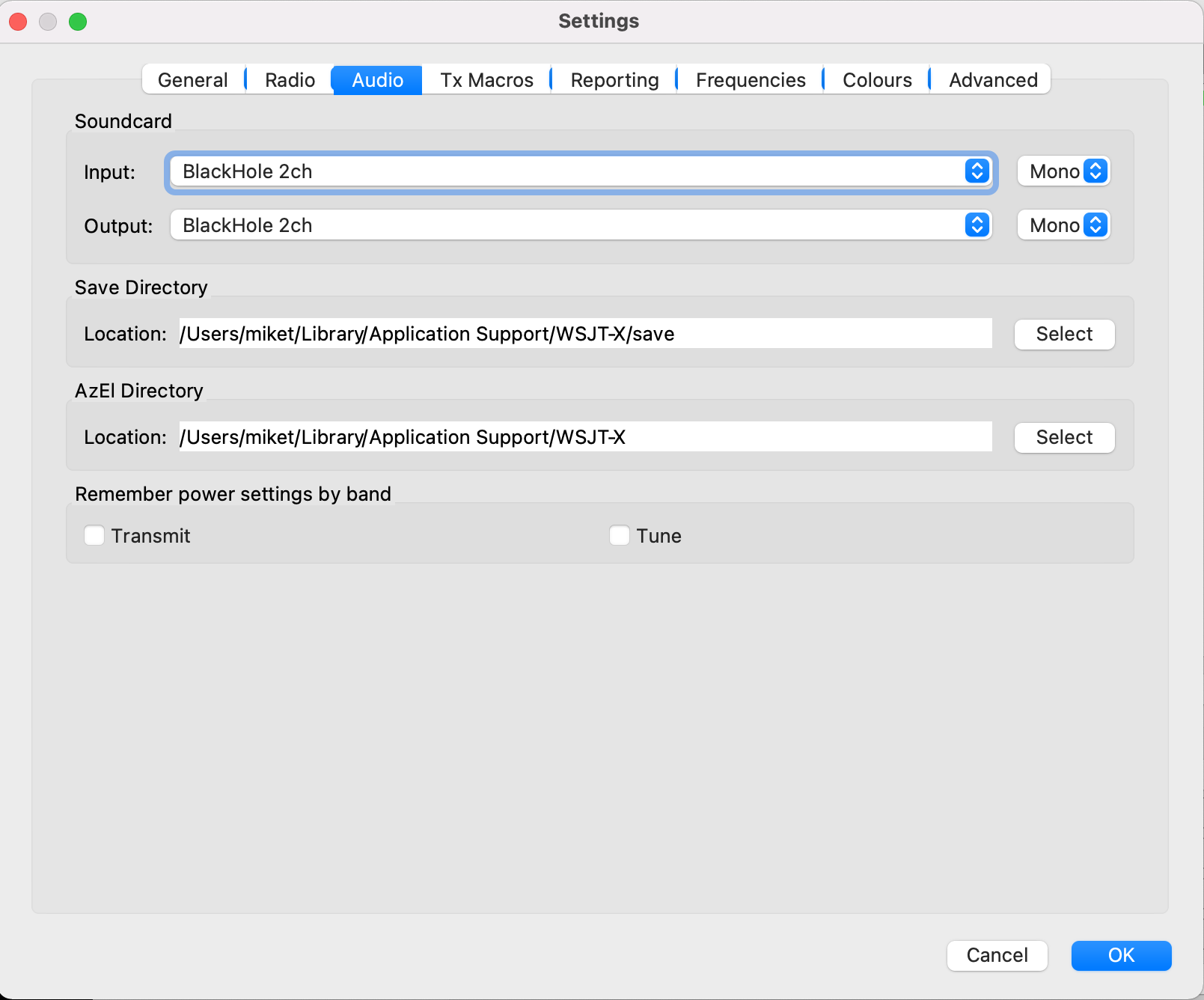
Next select the WSJT-X Audio Settings tab and set the soundcard Input/Output fields to Blackhole 2ch. Set both Input and Output to Mono as shown below.
WSJT-X Audio settings
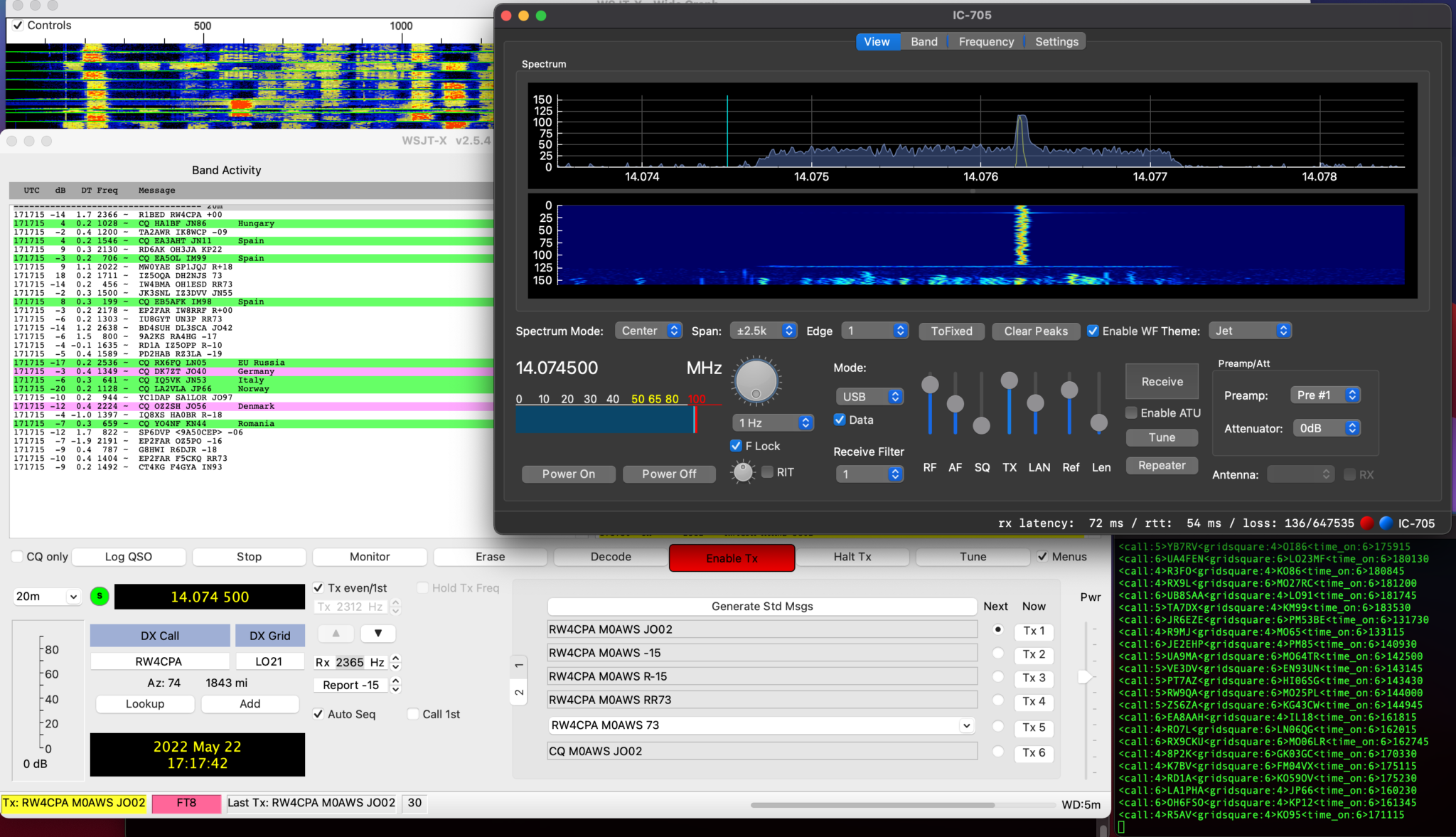
Click OK and return to the WSJT-X main screen. You should now be fully operational for WSJT-X digital modes.
WSJT-X transmitting through WFView to the IC-705
Once I’d made a few contacts with WSJT-X in FT8 mode I went on to try and get FLDigi working with WFView as well.
Unfortunately at the moment I cannot get CAT control working in either FLDigi or FLRig, neither will accept the /dev/ttys000 as the serial device however, I was able to get the audio working into FLDigi and even decoded some morse with it. I need to do little more work to fathom out why the CAT control doesn’t work in these two applications. I’m sure there is a way to resolve this but, I just need to put in a little more time to find the solution.
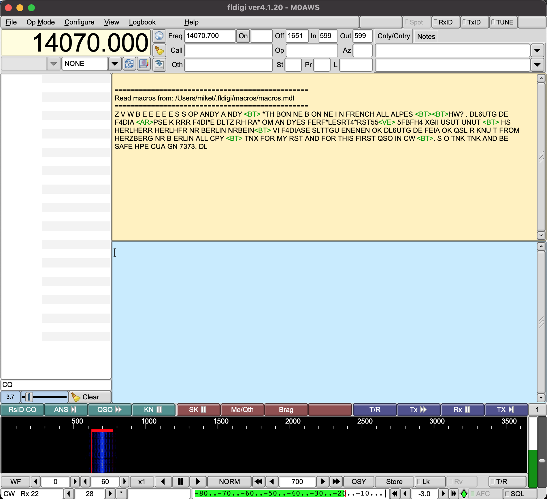
FLDigi decoding Morse code via WFView
UPDATE: There was some concern in one of the IC-705 Facebook groups that Blackhole wouldn’t work after a MacOS update. I’ve just upgraded my Macbook Pro to MacOS 11.6.6 and BlackHole is still fully functional afterwards. The MacOS update has no effect on the BlackHole service whatsoever. So you can rest easy!
Since getting my Icom IC-705 I’ve had a constant issue with interference on the HF bands from the USB connection on the radio when the AH-705 remote auto ATU is connected.
If I use the radio without the AH-705 inline there is no issue at all but, as soon as the AH-705 is connected to the radio there is some 9 S points of computer data noise across all the HF bands rendering them unusable.
Reading online this appears to be a common issue and so I set about trying to find a resolution.
The noise is most likely being induced onto the outer braid of the screen on the cables and so I decided to look into making a common mode choke.
Visiting the HAM Goodies website I ordered a couple of FT240-31 Ferrite Toroids as I’d read this particular mix is ideal for making common mode chokes.
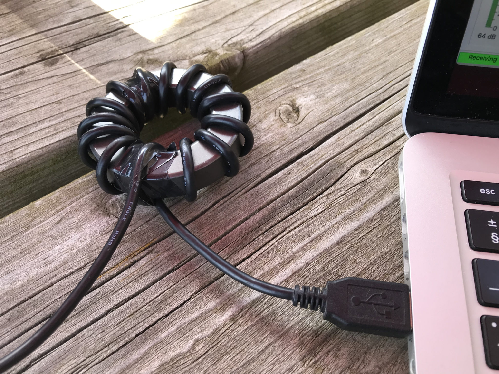
USB Cable wrapped around a FT240-31 Ferrite Toroid to create a choke
I wrapped a long USB cable around the toroid and used some tape to hold the cable in place, it’s surprising how much length is lost by simply wrapping around what looks like a very small toroid.
Firing up the radio the noise was reduced considerably but, it was still there and so I decided to do the same to the coaxial cable between the AH-705 and the IC-705.
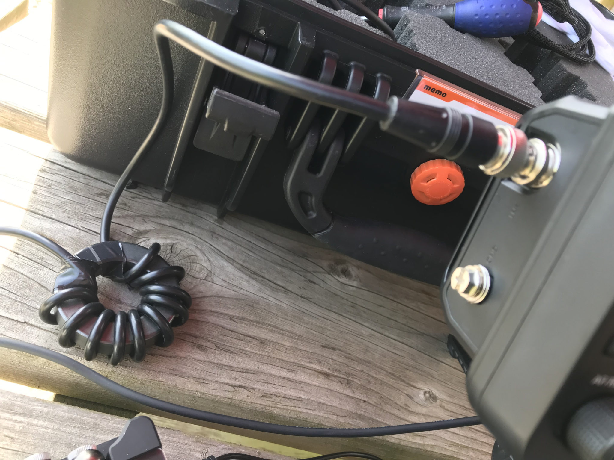
Coaxial cable between AH-705 and IC-705 wrapped around a FT240-31 Ferrite Toroid
Once I’d wrapped the coax around the toroid and reconnected the coax between the radio and ATU I was pleased to see that the computer data noise was now gone on all bands except for the 10m band. For some reason the 10m band interference is still as strong as it was without the toroids in place.
I’m not too sure why this is. I tried more and less turns on the toroid to no avail and so eventually I decided to just live with it for the time being.
At least now I can use 160m -> 12m without any interference whatsoever, a massive improvement on what I had before.
I need to do some more research on the different mixes of the ferrite toroids and perhaps trying a different mix will resolve the problem on the 10m band too.
One of the things I’ve had issues with ever since purchasing the Yaesu FTDX10 transceiver is control of the audio chain via the USB connection on the rear of the radio.
The output from the radio into my Macbook Pro is just too high, WSJT-X is constantly pushed beyond the green zone and often into the red zone when monitoring FT8 signals with the AGC off. The only way to cure this is to keep the AGC on Auto which sometimes results in not hearing the very weak DX stations due to the AGC not reacting fast enough. Putting the AGC on fast causes the red line to be hit far too often once more.
Sadly, the USB Audio Codec doesn’t provide any volume adjustment on audio coming from the radio into the MacBook Pro thus, it’s just full volume all the way. This is a flaw in the codec design and really does need to be resolved long term.
Looking at the audio going the other way, that is from the MacBook Pro into the radio via the USB port fortunately there are gain controls available both on the MacBook Pro and on the radio itself.
Ever since venturing into the world of WSJT-X & FT8/4 I’ve had an issue with only being able to move the PWR slider in the WSJT-X up to the first marker at the bottom of the screen, anymore and the ALC on the radio goes off the scale instantly!
So yesterday I decided to investigate the audio chain into the radio more thoroughly and see what could be done about the levels.
Looking at the radio manual I found that there is an RPORT GAIN setting in the menu system that can be used to alter the amount of gain applied to the incoming audio signal on the USB port in the radio.
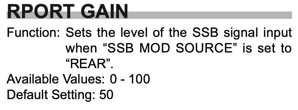
FTDX10 Rport Gain entry in the manual
As detailed in the manual, the default setting for this is 50 in a range of 0 to 100. So that’s a 50% increase in gain applied to the incoming audio at the radio end, that’s quite a boost! (The gain is applied both in SSB and Data Modes)
I decided to experiment reducing this figure to see if it gave me greater control over the audio output from WSJT-X via the PWR control. This did indeed help however, there was still too much audio coming into the radio from the MacBook Pro and so I needed to look further along the audio chain.
Moving back onto the MacBook I opened the Midi App and took at look at the Output controls for the USB Audio Codec, sure enough this was set to max for both channels, not good.
Reducing the levels in the midi app started to make much more of a difference, I could now raise the audio level using the PWR control in WSJT-X without things immediately going wild and could now control the levels with a far greater level of granularity than ever before.
After much tinkering I eventually found the levels whereby I could drive the rig to the selected output power (20w) without the ALC going off the scale and the signal becoming horribly distorted, there was calm in my audio chain once more.
So what settings did I settle on?
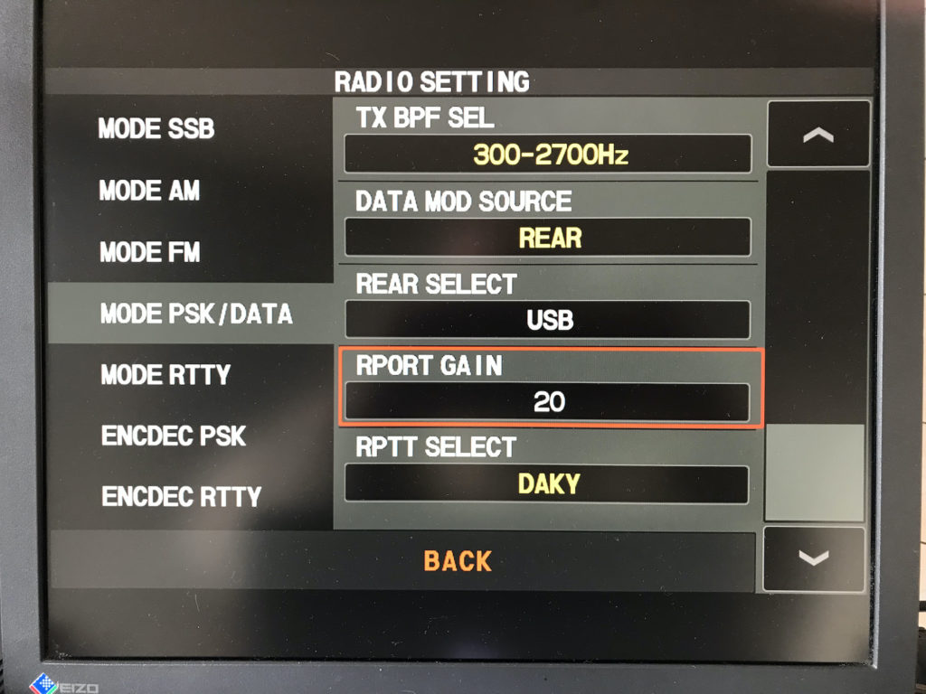
On the radio itself I wound down the RPORT GAIN setting from 50 to 20, this reduced the amount of gain applied to the audio coming in on the USB port considerably and helped to tidy up the FT8 signal.
FTDX10 RPORT GAIN Setting reduced from 50 to 20
It’s great that there is the facility on the radio to reduce the gain on the inbound audio signal, if only Yaesu would do the same for the outbound audio level.
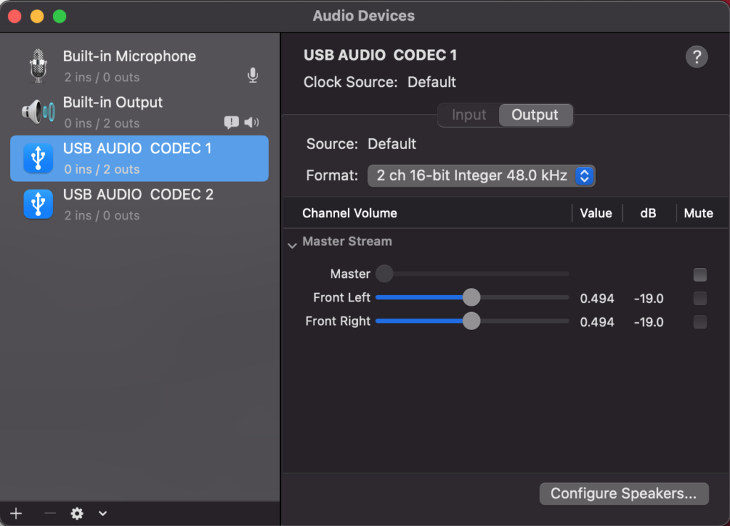
Next, on my MacBook Pro via the Midi app I reduced the output level on the USB Audio Codec from the default maximum down to 0.494 (-19). This stops the audio level from being too high going into the radio and removes all distortion from the resulting signal.
Midi App on Macbook Pro showing reduced audio output
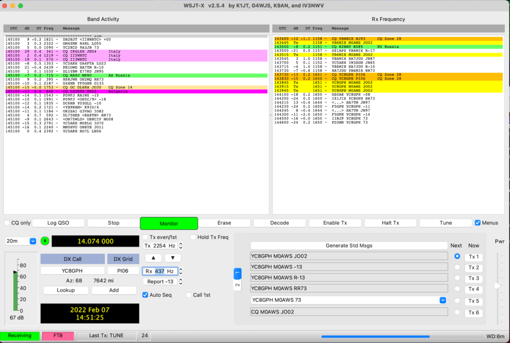
Once these small changes have been made it becomes necessary to raise the PWR level in the WSJT-X app to roughly the centre position. At this point the radio gets a clean, distortion free audio input whilst driving the radio to the full 20w output with no movement on the ALC whatsoever.
I found I could move anywhere on the frequency spectrum on FT8 without any of the levels changing and with the ALC not moving whilst the radio delivered the full 20w output.
I also checked FT4 mode as it is an MFSK mode to see if these settings worked for it too and I’m glad to say it worked perfectly! (I also found I really liked FT4!)
WSJT-X with the PWR setting at roughly 50%
Altering the PWR level in WSJT-X doesn’t have the huge effect it had before and now it’s very easy to adjust the level without the ALC going off the scale in an instant.
It took me about an hour or so to get this just right but, it was well worth the time invested.
I hope this is of use to other Apple Mac computer users in the HAM community.
More soon …
We use cookies to ensure that we give you the best experience on our website. If you continue to use this site we will assume that you are happy with it.