Node-Red Control Dashboard for AllStarLink 3

I’ve recently built a new AllStarLink (ASL) node for my MB7IBW gateway that I have recently brought up on air on the 2m band.

AllStarLink 3 has a lot of changes in it when compared to the previous version and this of course impacts my Node-Red Control Dashboard that I’ve been using to manage my first ASL node for well over a year now.

To build the node I used the RaspberryPi imager and added the AllStarlink 3 image as detailed on the allstarlink.org website.

Installing the system this way makes it pretty easy compared to previous installs but, it comes with some quirks which cause issues with Node-Red.

From the outset the plan has always been to have AllStartLink 3 and Node-Red running on the same Pi4 to keep it totally self contained. This was easy enough to achieve and works without issue.
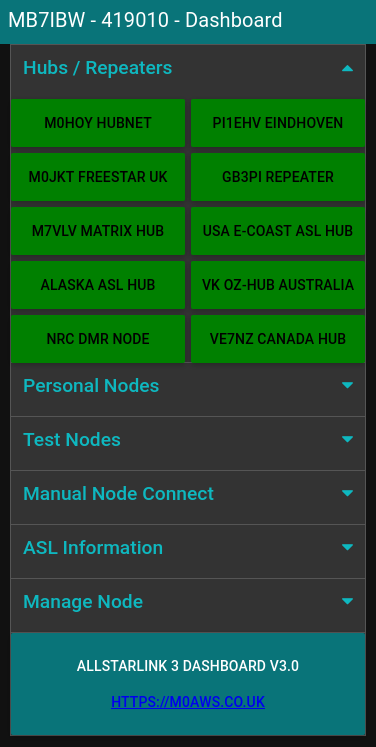
Node-Red Control Dashboard for AllStarLink 3

Installing Node-Red onto a Pi4 is really easy and is fully documented on the Node-Red Website.

Once the AllStarLink 3 operating system was installed on my SD card, booted and operational I installed Node-Red. I soon realised that there were a few things I had to do before loading the Node-Red flow.

AllStarLink 3 no longer logs connect and disconnect messages in the connectlog like it did in AllStarLink 2. To get logging working again I had to create two new BASH scripts as detailed below and put them into /etc/asterisk/myscripts.

For the connect information I created the BASH script as detailed below.

#!/bin/bash

# /etc/asterisk/myscripts/connectlog.sh

echo $1 Connected $2  on $(date +"%T") - $(date +"%m-%d-%Y")  >> /var/log/asterisk/connectlog

For the disconnect information I created the 2nd script detailed below.

#!/bin/bash

# /etc/asterisk/myscripts/disconnectlog.sh

echo $1 Disconnected $2  on $(date +"%T") - $(date +"%m-%d-%Y")  >> /var/log/asterisk/connectlog

Once these scripts were created I had to change the ownership and privileges as detailed below.

cd /etc/asterisk/myscripts
chown asterisk:asterisk ./*
chmod 750 ./*

I also had to change ownership/privileges of /etc/asterisk/myscripts.

cd /etc/asterisk
chown asterisk:asterisk ./myscripts
chmod 755 ./myscripts

Once the two scripts were in place I had to alter the asterisk config so that it called the scripts as part of the connect/disconnect process.

I found the connpgm and discpgm entries in /etc/asterisk/rpt.conf and changed them as shown below.

connpgm = /etc/asterisk/myscripts/connectlog.sh

discpgm = /etc/asterisk/myscripts/disconnectlog.sh

Next I disabled the temporary filesystems that are used by default for the apache and asterisk logging as it’s useful to keep the apache logs for debugging and I needed the asterisk logs for the Node-Red dashboard.

Disabling the temporary file system is very easy to do, just edit the /etc/fstab and comment out the two lines as shown below.

# Comment out the next line for persistent Apache logs
#tmpfs  /var/log/apache2        tmpfs   defaults,noatime,nosuid,nodev,noexec,mode=0775,size=32M 0 0

# Comment out the next line for persistent Asterisk logs
#tmpfs  /var/log/asterisk       tmpfs   defaults,noatime,nosuid,nodev,noexec,mode=0775,size=32M,uid=102,gid=106 0 0 

# Note: These lines are wrapped, should be on 1 line in the /etc/fstab

Once the entries in the /etc/fstab were commented out I rebooted the Pi4 to get persistent filesystems.

The final thing that had to be done was to allow user repeater to use sudo without a password so that it could be used to perform reboot/shutdown/process restart as user root from within the dashboard.

# /etc/sudoers

# Allow repeater sudo without password
repeater ALL=(ALL) NOPASSWD: ALL

Once this was all done I imported the Node-Red flow, configured the SSH nodes with login credentials for the Pi4 (important to use the user repeater for SSH), clicked deploy and the dashboard was ready for use.
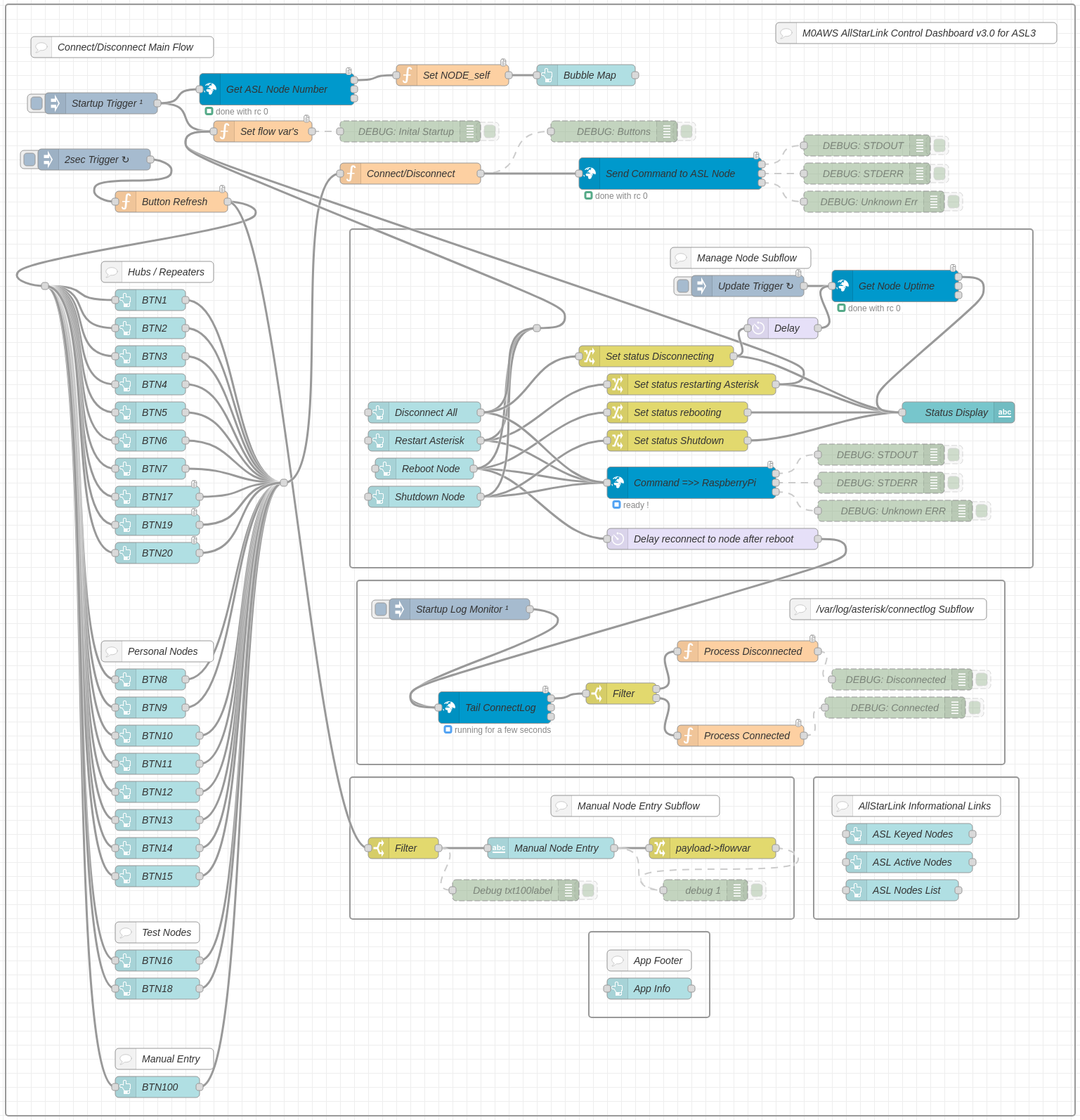
Node Red AllStarLink3 Control Dashboard Flow

I’ve been using the dashboard for a few weeks now and it’s running perfectly, without error.

If you want to build your own Node-Red Control Dashboard for your AllStarLink 3 node then, just download the flow using the button below and import it into your flow editor.


More soon …
Bring your old handheld to life with an AIOC

I’m sure there are many radio amateurs around the world today who have an old handheld radio sat on the shelf that works perfectly but, has been replaced by a new, shiny, all singing, all dancing model that gets used on a daily basis. I for one have fallen into this trap with the recent purchase of a very nice Wouxun KG-UV9K full duplex 2m and 70cm handheld.

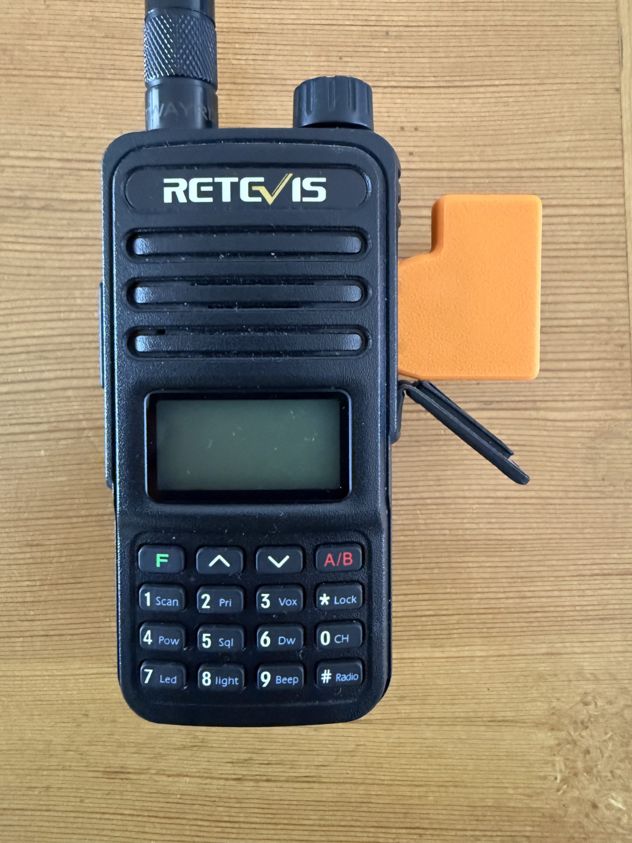
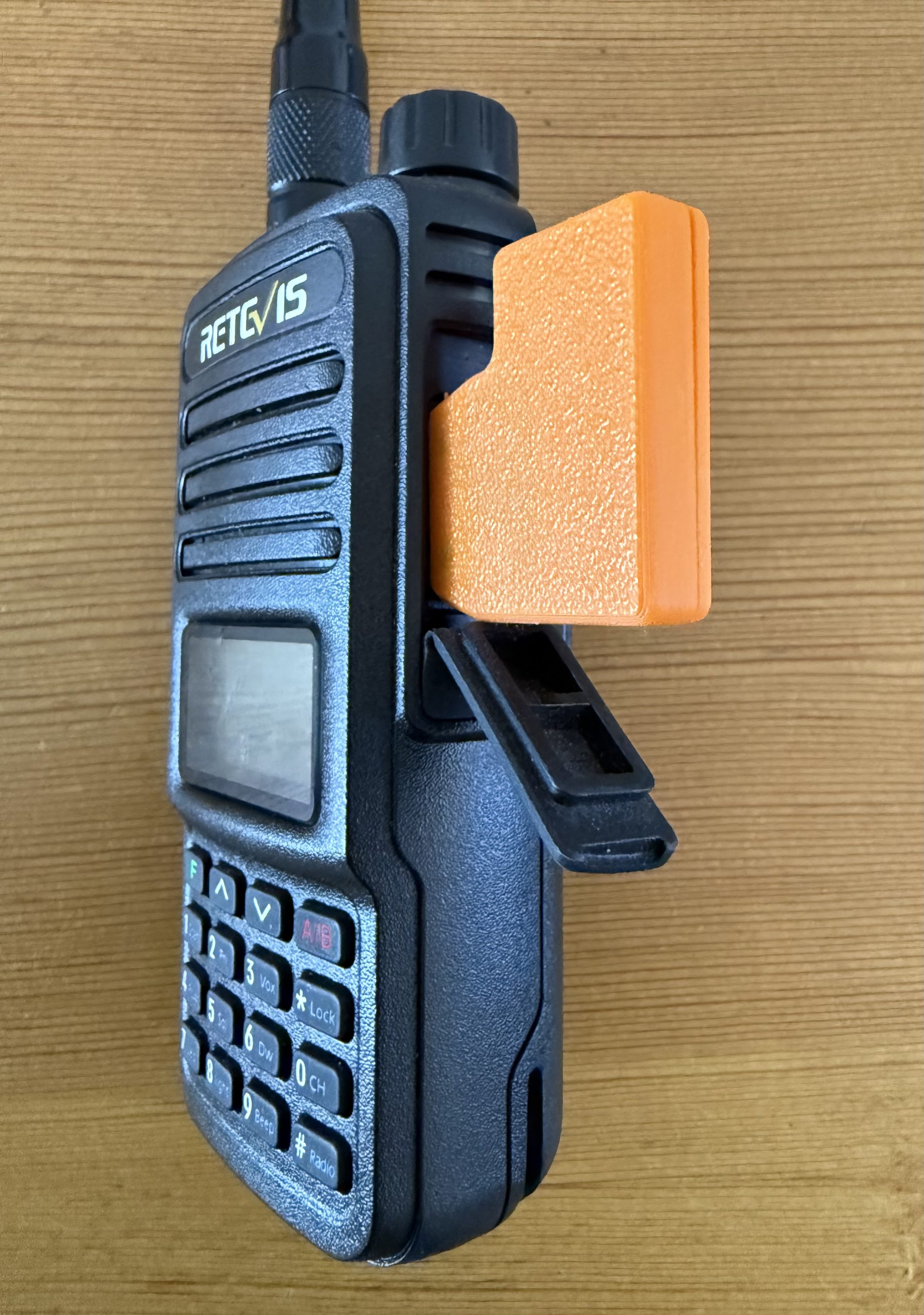
On my shelf there is a cheap Retevis RT85 that gave sterling service for a number of years and even today is ready to continue that service, if only I had a need?

Well now I do!

Currently I have an AllStarLink node running on a RaspberryPi 3b connected to a SHARI device that operates on the 70cm band. This node works great and gives me the ability to chat with people all over the world from my trusty handheld. It does of course also give me access to the weekly Matrix AllStarLink Net that happens on our Matrix node ( 642332 ) every Thursday evening at 20:00 UK time, a great way of bringing the Matrix HAM Radio community together regardless of propagation.

For some time I’ve been wanting to bring another AllStarLink node online so that I can have a connection to HUBNET/FreeNet whilst keeping my current node connected to the Matrix node for our regular daily chats. Since my new Wouxun handheld is a full duplex unit it makes sense to bring a new node up on the 2m band as I can then monitor both at the same time easily. I do have a spare SHARI node however, it’s a UHF only unit and I don’t want another node on the 70cm band. This is where the old Retevis RT85 comes in to play.

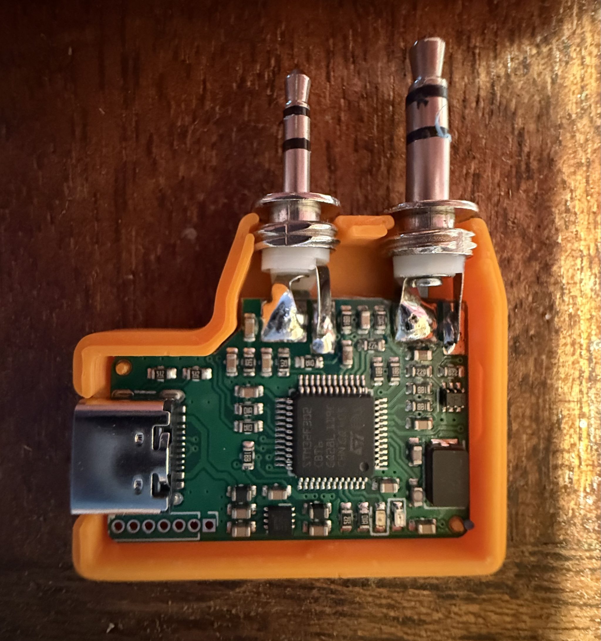
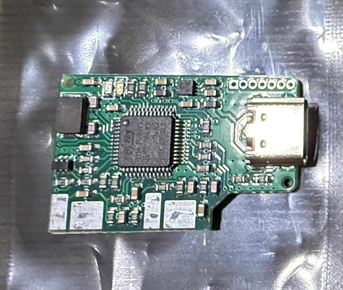
The All In One Cable ( AIOC ) board is a very neat little CM108 compatible sound card and serial interface that is sold by Steve, KM9G of YouTube fame ( Temporarily Offline ) that plugs into any handheld radio that has the now pretty much standard Kenwood ‘K’ type mic connector.

AIOC board from Steve, KM9G.

The AIOC board really is tiny but, beautifully put together. The four large solder pads on the top and more on the underside are positioned such that the TRS plug solder lugs line up perfectly for soldering. Attempting to do this by hand would be impossible as it’s critical that the spacing between the two connectors matches that of the spacing of the sockets on the radio.

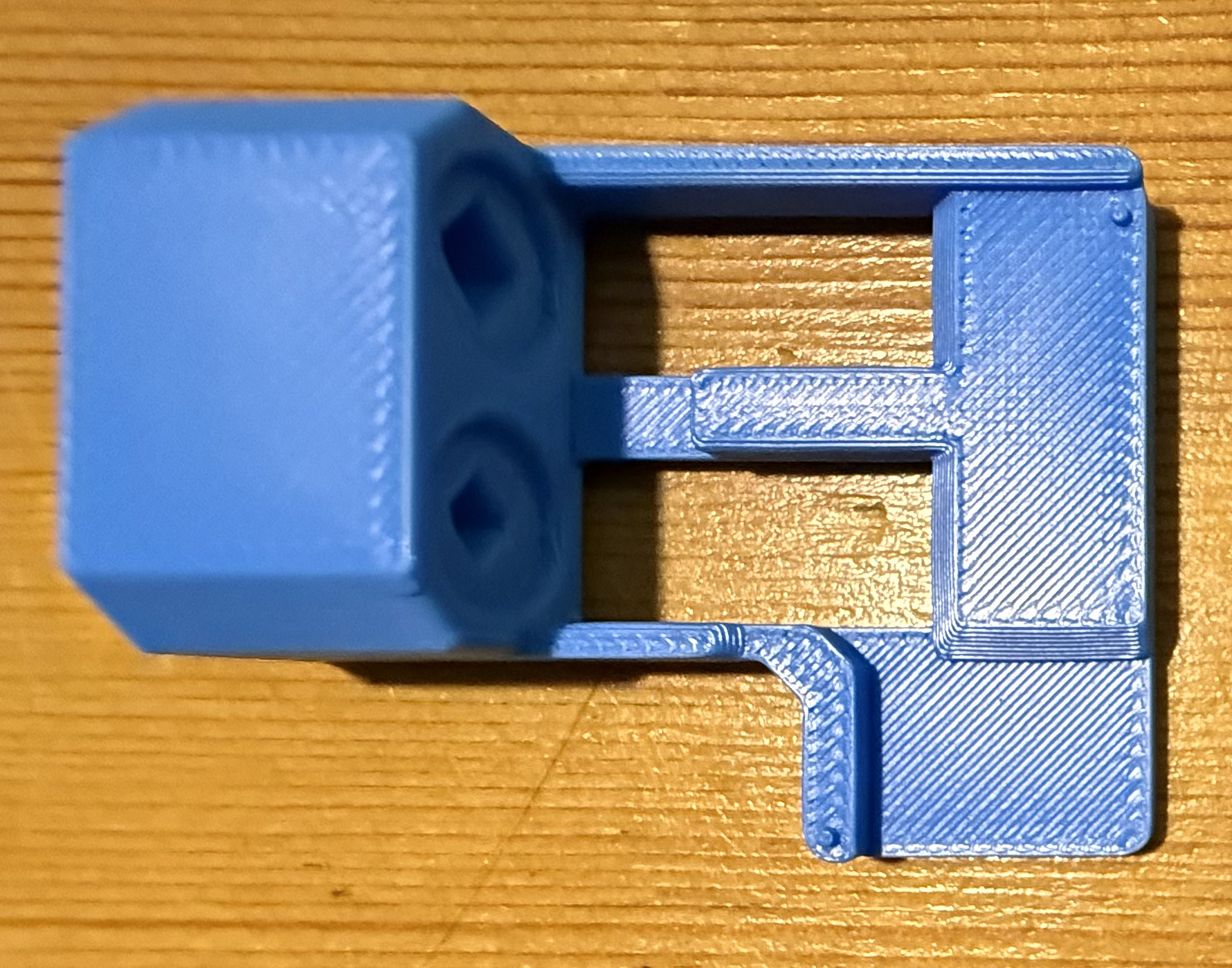
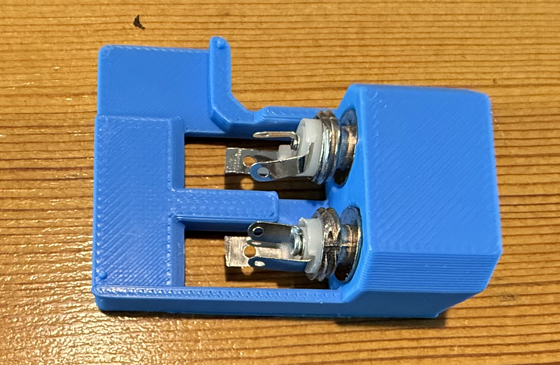
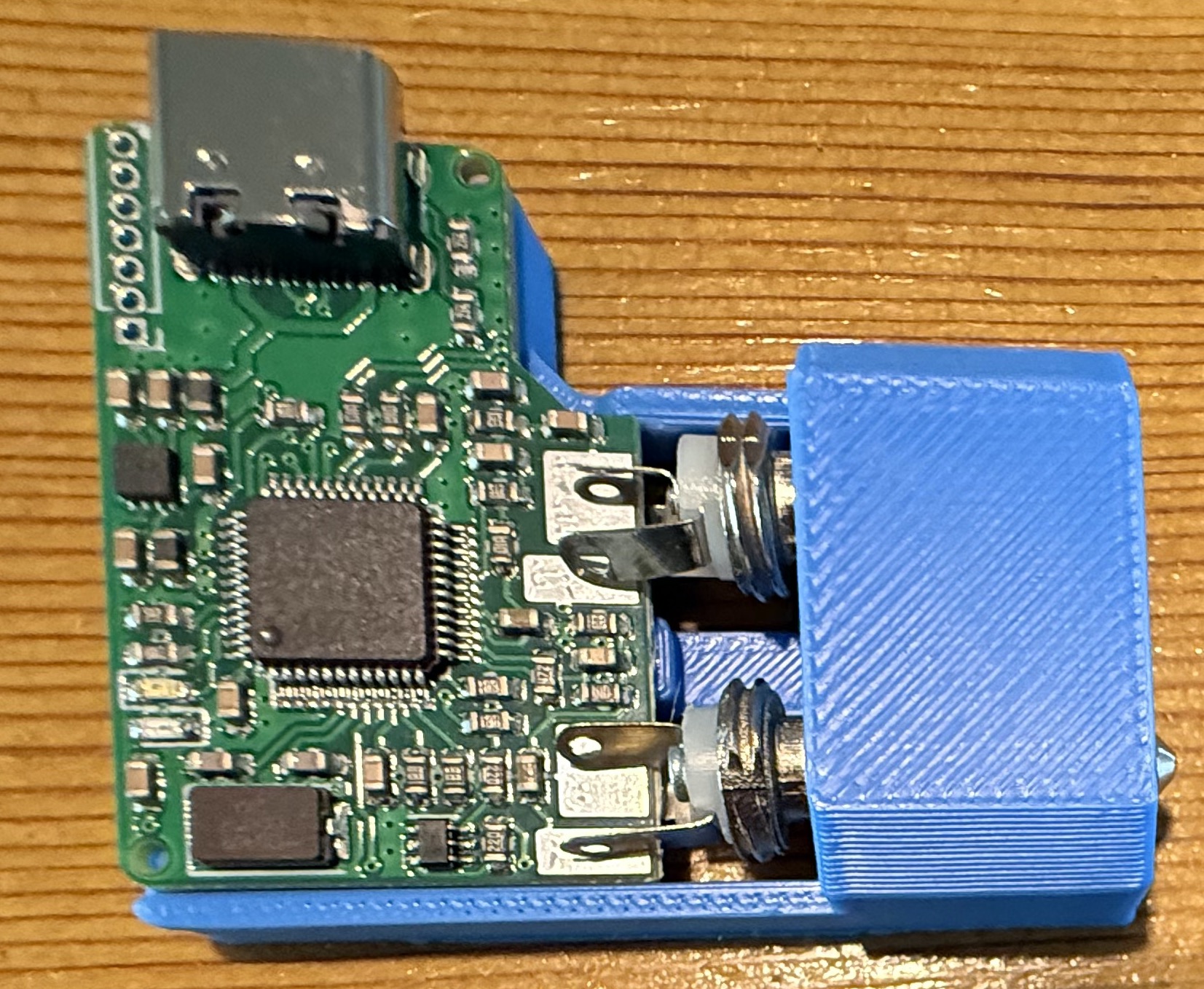
AIOC Solder Jig.
AIOC Solder Jig.

Searching online I found a very handy soldering jig on Github that enables you to hold both the TRS connectors and AIOC board in the perfect position for soldering.

Downloading the .STL file I quickly printed off a solder jig on my Bambu Lab A1 Combo 3D printer and fitted the components into place ready for soldering.

Everything fitted rather snugly into the jig and I soon had the board and connectors soldered together. Test fitting to my Retevis RT85 I found the TRS plugs lined up perfectly and it slid into the sockets with ease.

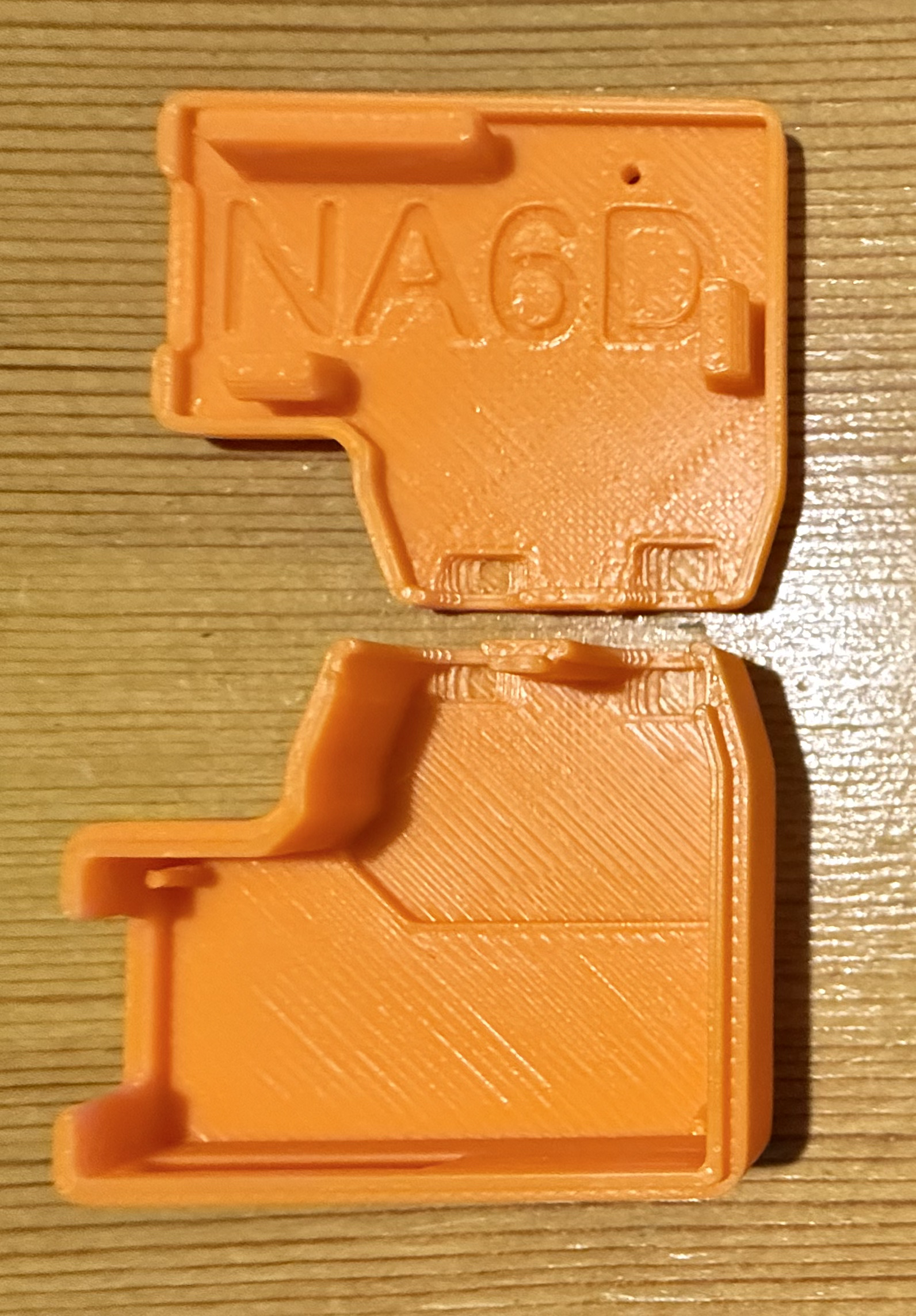
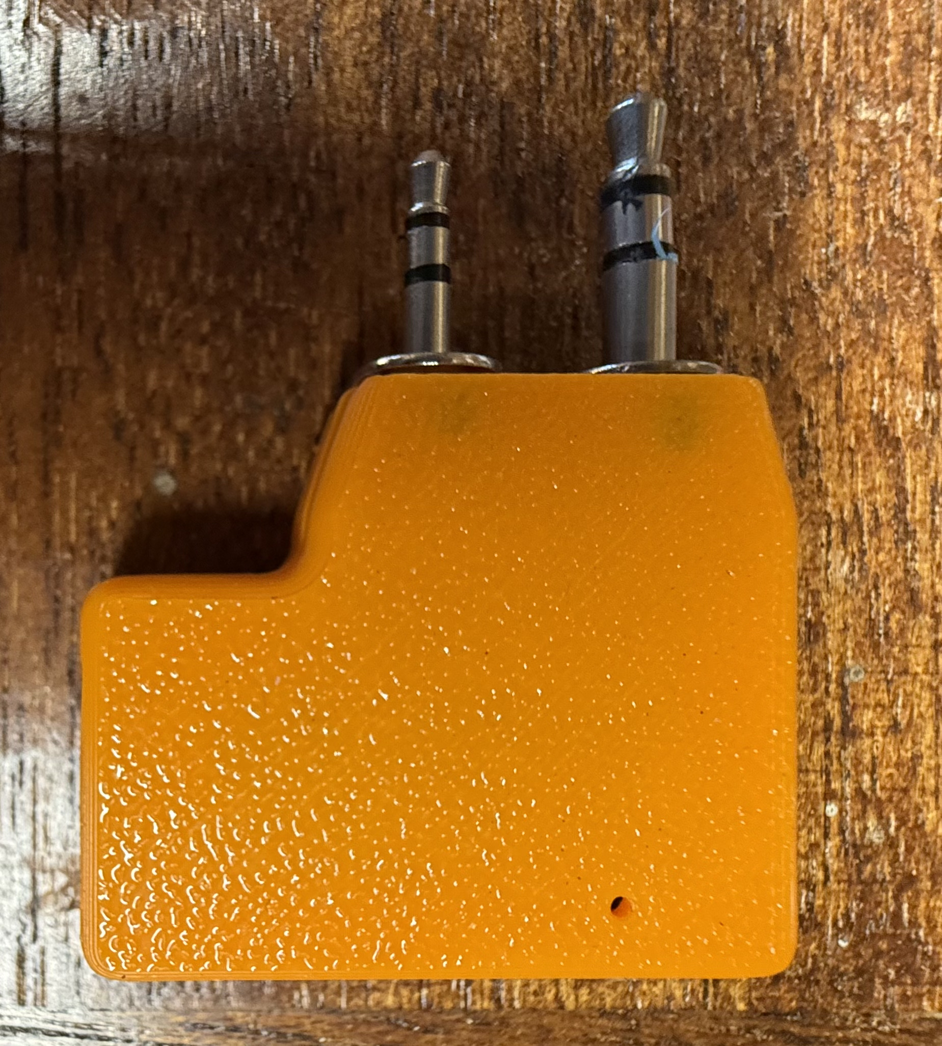
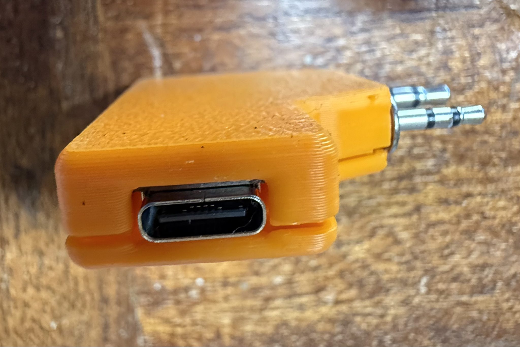
I then thought about designing a case for the AIOC board so that the bare circuit was nicely protected but, quickly searched online and found that NA6D has already designed a case and made the .STL available publicly for download on Printable.com. I quickly grabbed a copy of the file and punted it off to my 3D printer to get to work on.

3D print NA6D AIOC case.

Once the print was complete I fitted the AIOC board and snapped it together ready for testing.

Now that the AIOC was production ready I moved on to getting the latest version of AllStarLink onto my RaspberryPi 4 that I had taken out of my RadioBerry based shortwave receiver that I am going to upgrade to a Hermes Lite 2 in a later project. The RaspberryPi 4 is perfect for AllStarLink 3, a 64bit app and operating system.

Using the RaspberryPi Imager I pulled the image down onto an SD card and slipped it into my Pi4. ( Instructions on how to do this are on the AllStarLink website here )

Booting the Pi4 for the first time I found that it went through a number of reboot and configuration cycles before it was ready for use.

Once ready I went through all the normal configuration of the Pi4 namely, static IP assignment, timezone config, security, port forwarding etc etc.

Having configured an AllStarLink node for myself and only just a few days ago for another HAM I was pretty familiar with the setup. Wanting to make sure there were no “gotcha’s” I also watched a couple of KM9G’s videos on Youtube to make sure I wasn’t missing anything.

Using the asl-menu command line app as user root I set about configuring Asterisk to work with the AIOC board. Much to my frustration I could not get Asterisk to recognise the AIOC board as an available sound device. I checked and double checked all the settings ensuring that I had selected “AIOC” in the available devices menu but found that Asterisk constantly errored saying it could not find the selected audio device. This went on for a whole day without success and so, I decided to put it to one side and come back to it later, a method I found that often worked.

A couple of days later I revisited the problem and had decided to take a different approach. Rather than continue going through the asl-menu app I decided to drop down to a lower level and go through the asterisk config files in the /etc/asterisk directory.

It wasn’t long before I found a file called res_usbradio.conf. Inside this file was the config for the AIOC board however, it was all commented out which meant it was disabled.

I’m guessing here but, I imagine this is what should get enabled when selecting AIOC in the available devices menu in the asl-menu command line app but, for some reason it doesn’t happen.

[general]
;usb_devices = 1209:7388    ;comma delimited list of usb
                            ;descriptors to allow.
                            ;format vvvv:pppp in hexadecimal
                            ;vvvv=vendor id, pppp=product id
                            ;
                            ;1209:7388 = AIOC (all in one cable)

Above is the disabled configuration which is easily edited to enable the AIOC device as shown below.

[general]
usb_devices = 1209:7388    ;comma delimited list of usb
                            ;descriptors to allow.
                            ;format vvvv:pppp in hexadecimal
                            ;vvvv=vendor id, pppp=product id
                            ;
                            1209:7388 = AIOC (all in one cable)

Once the updated file had been saved and I restarted Asterisk using systemctl the AIOC burst into life and Asterisk recognised it immediately. The Retevis RT85 switched between TX and RX and I was ready to check out the audio.

Setting the volume levels for both RX and TX via the command line tuning app I connected the node to my already existing node. Sure enough the two nodes connected without error and I was able to send and receive audio between them via the AllStarLink net.

Connecting the new node to the parrot I checked the audio levels to ensure it sounded ok and then connected it to the Matrix node where I had a brief chat with Ben, M8TKK.

All that is left to do now is to 3D print a case for the Pi4 so that it isn’t left naked and at risk of being shorted out on conductive surfaces and it’ll be ready for service.

I also plan to build another AllStarLink node using a 4m band handheld and another AIOC board and then will apply for MB7Ixx callsigns for the two new nodes. This will hopefully help to bring some life to the 2m/4m bands locally and introduce HAM’s both to the weekly Matrix Net and HUBNet/FreeStar via AllStarLink.

More soon …

Xiegu XPA125B Button Press

For some time now I’ve been using my Xiegu XPA125B amplifier with my Hermes Lite 2 + I/O board combo with great success. With the amp changing bands automatically it really is nice to use.

With the multitude of remote controlled smart plugs available today I’ve now got the ability to switch the station on remotely however, there’s been one issue that has plagued me until now and that’s the Xiegu amp doesn’t come on when power is applied to it, you have to press the power button on the front of the amp before it will fire up.

This of course stops me from being able to fully use the station remotely as there’s no one there to press the power button on the amp, until now.

Chatting with Steve, M0XVT he discovered that if the power button is held pressed all the time the amp will come on when power is applied. This then gave me the idea of designing a button press device that I could 3D print and clip onto the front of the amp so that the button is always pressed.

M0AWS Xiegu XPA125B Clip on Power Button Press

The Xiegu amp has a very nice flange around the front edge of the amp case that lends itself nicely to clip on a simple button press device as shown above in my 3D design software.

The button press is designed so that the top is put on first and then the bottom is just snapped into place with a gentle push. This makes it easy to get on and off without marking the amplifier.

M0AWS Xiegu XPA125B Clip on Power Button Press

In just a few minutes I had the button press design uploaded to my Bambu Lab A1 Combo 3D printer and in no time at all the button press was ready for use.

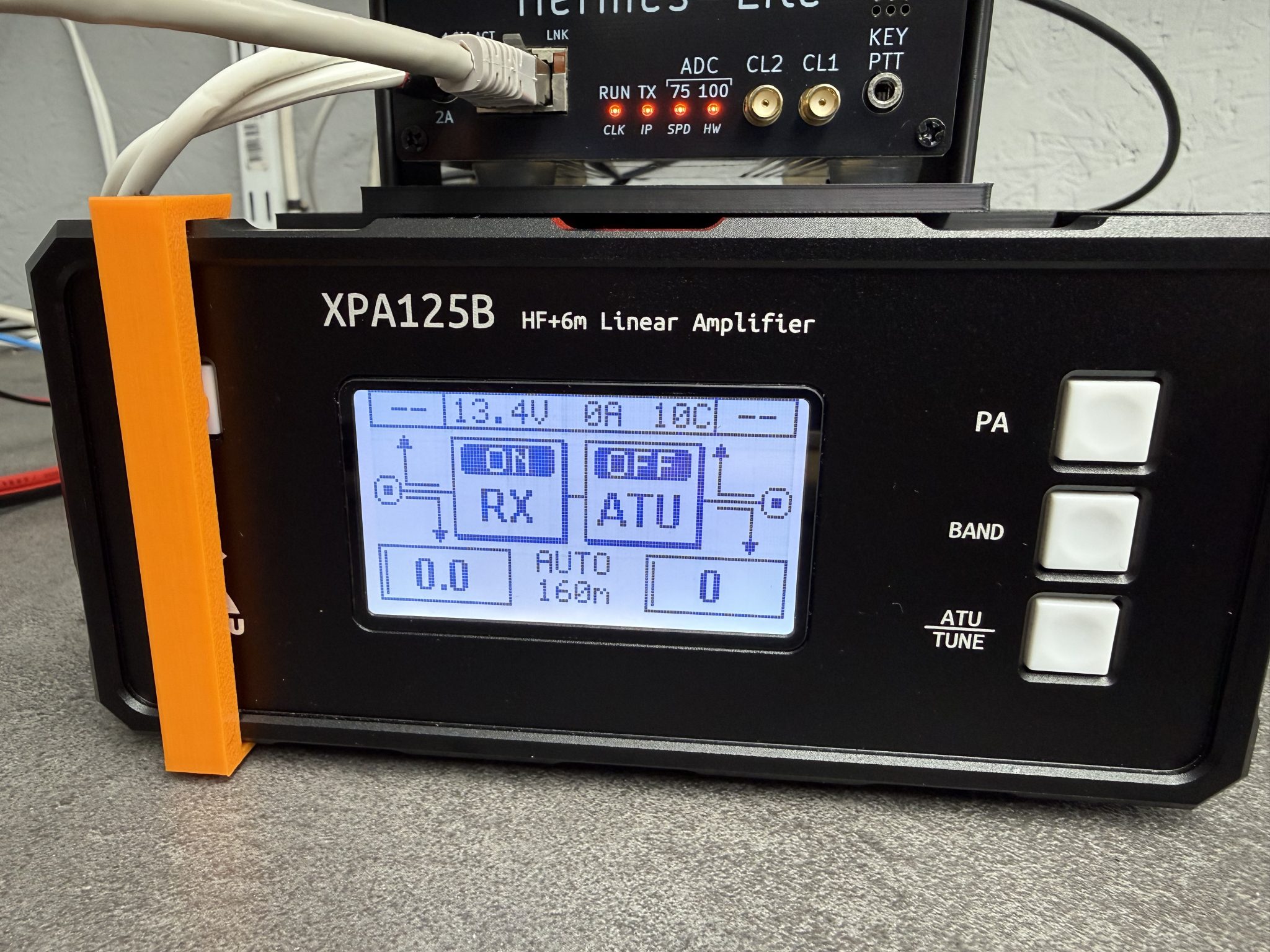
As you can see in the photo above it fits snugly to the front of the amp gently holding the power button in so that the amp comes on when power is applied. Simple but, effective.

I’m sure I’m not the first person to have this problem and so, I’ve made the .STL 3D print file available for download below.


I hope this is of use to people who want to be able to use their Xiegu amp remotely without leaving the power on all the time.

More soon …