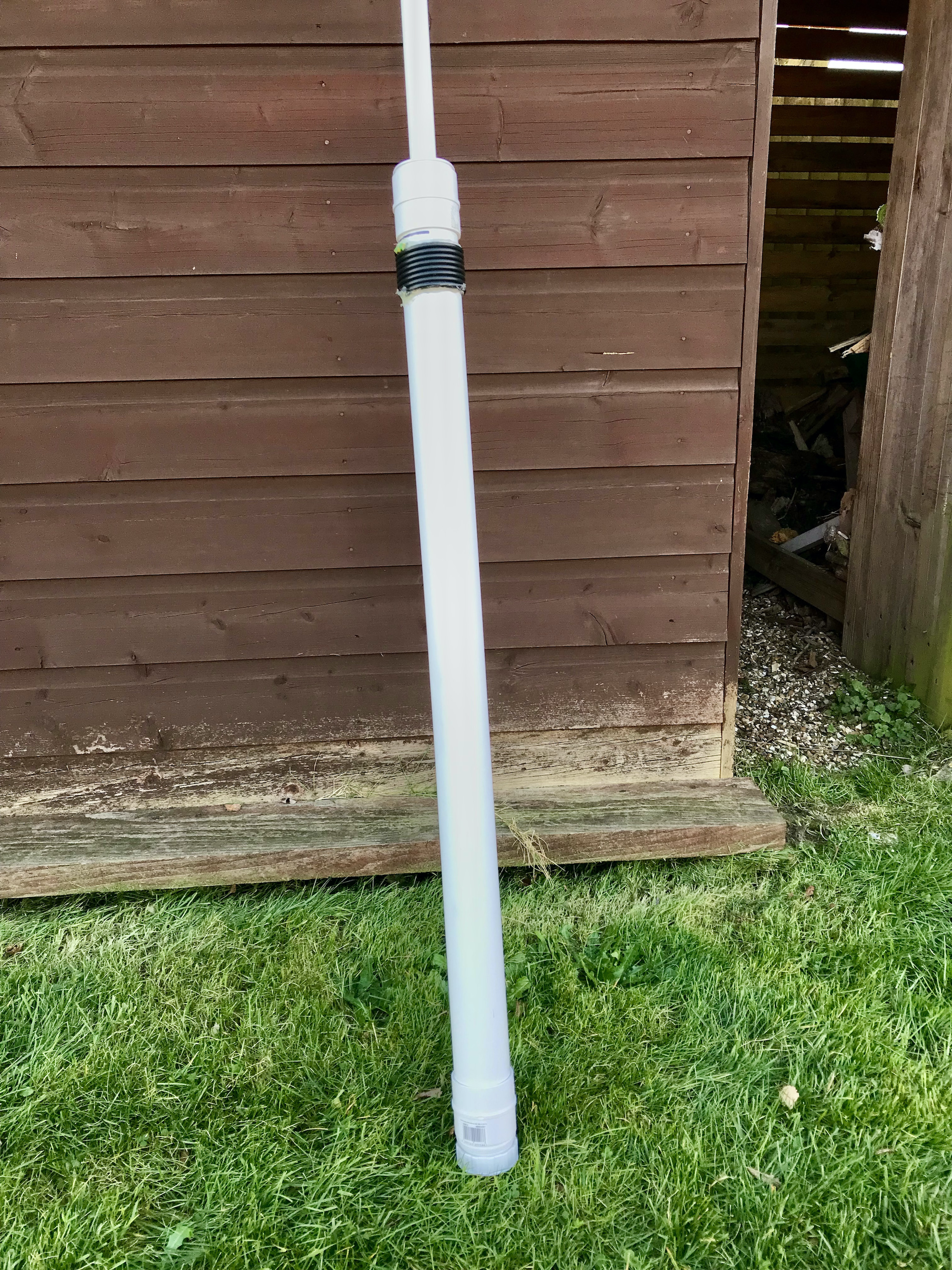
A question I get asked regularly is:
“Why don’t you mount your 20m EFHW Vertical antenna higher up in the air?
It’ll work much better the higher you get it”.
I have over the years tried raising and lowering my vertical antennas for DXing and found that keeping the base of the antenna and feed point low has advantages over a raised installation. I’ll try and explain this using some 3D and 2D far field plots from the EzNEC antenna modelling software that I use.
Below are the 3D and 2D far field plots as I have it setup at the moment. The 49:1 Unun is at ground level with the base of the antenna also at ground level.
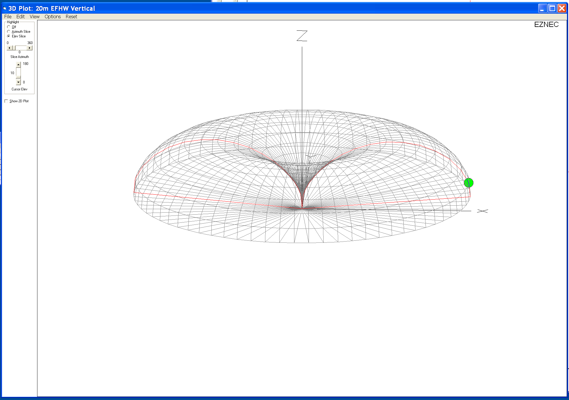
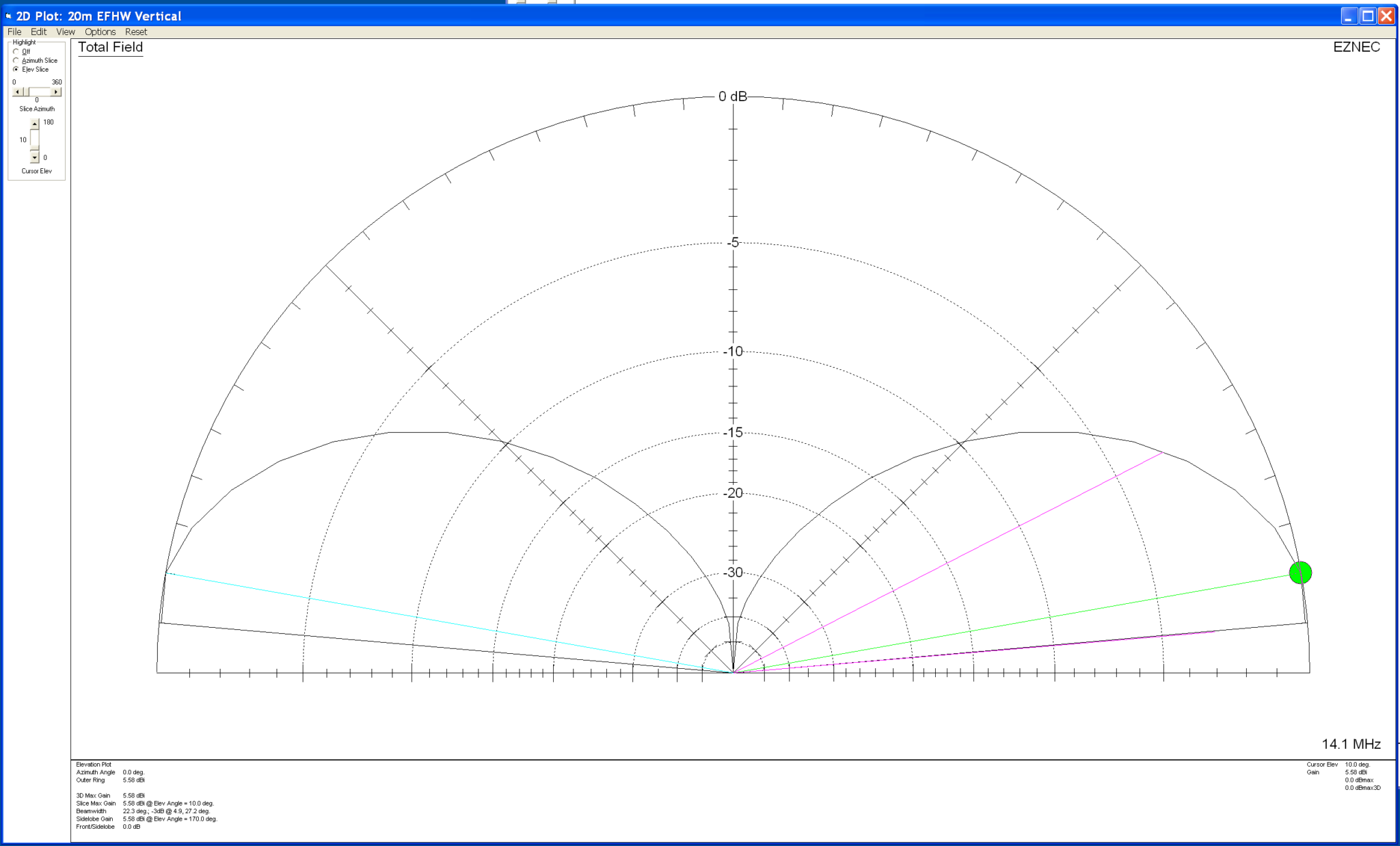
Forgetting about the dBi gain figures for the time being and just concentrating on the overall radiation pattern you can see that with the antenna fed at ground level it has a typical circular radiation pattern with a deep null in the centre and a very low angle of maximum radiation. This makes the antenna perfect for DXing and is backed up by the success I’ve had on the 20m band working Australia, Thailand, Indonesia, South America, West Coast USA and Canada. This is exactly what I wanted and I’m extremely happy with it’s performance. I must add that I’m not looking to work European stations with this antenna, I’m only looking for DX stations especially those with very weak signals.
So now let’s take a look at what happens to the radiation pattern when we raise the antenna and the feed point above ground level.
First let’s raise the antenna so that the base and feed point are 3m above ground level.


Looking at the two far field plots above you can see that with the antenna and feed point raised by 3m we start to get some high angle lobes appearing in the centre of the radiation pattern. The overall maximum radiation is still at a low angle and so this would still be good for DXing but, does have an element of high angle radiation to it now. This will of course mean we’ll start to be able to work stations much closer to us and also be able to hear them better.
Raising the base of the antenna and feed point to 5m above the ground we see that the high angle lobes get even bigger and start to distort the overall radiation pattern of the antenna.
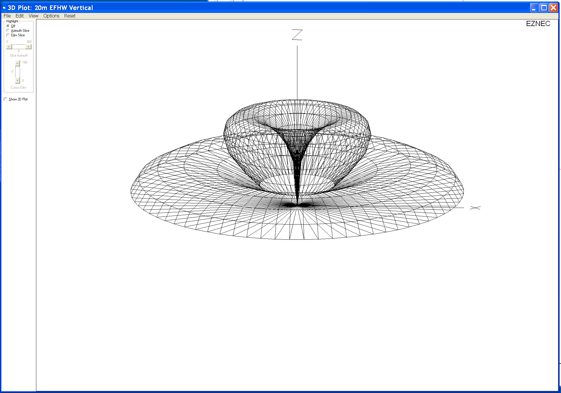

At 5m above ground the two high angle lobes have increased considerably which will result in more high angle radiation from the antenna. Maximum radiation is still at a low level though and so DXing will still be good with this setup but, from experimentation and experience I know that there are times when closer stations start to affect the ability to pick out the weaker DX stations. This is exactly what I don’t want.
Raising the antenna up even further to 10m above ground we get the following result.

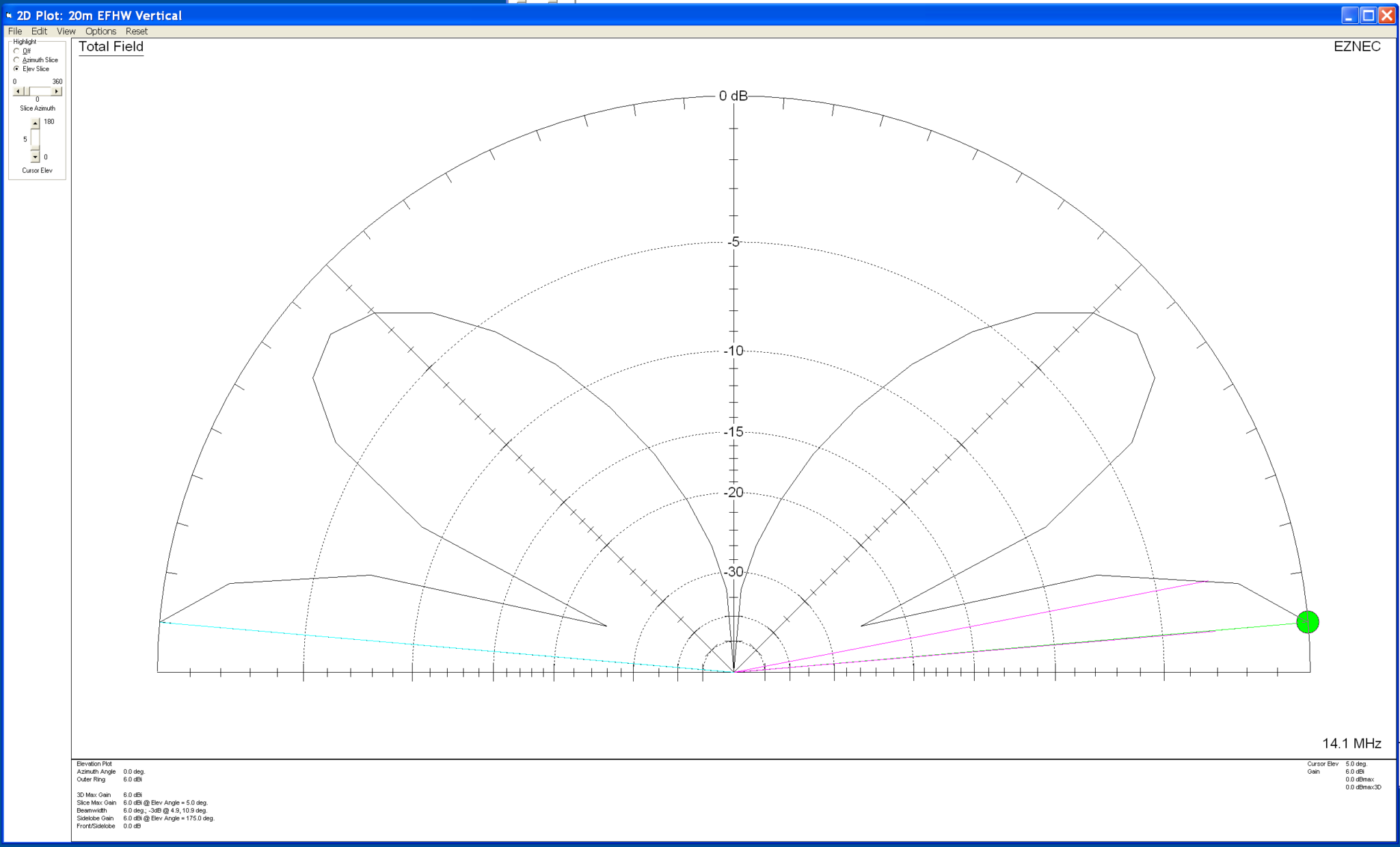
At 10m above the ground the two high angle lobes shown on the 2D elevation far field plot are now almost as big as the main lobe below it. This means there will be considerable high angle radiation from the antenna which will result in the ability to communicate with stations much closer to your QTH rather than focusing just on the DX stations.
If you’re looking for the best of both worlds then getting your antenna up higher is the way to go, you’ll be able to work stations in the 300-1500 miles range with ease and the DX stations thousands of miles away.
From my experience there is one disadvantage with this in that the closer stations tend to drown out the weaker DX stations reducing the overall DX capability of the antenna and this is why I keep the antenna feed point at ground level. From experimentation and experience gained over the years I’ve found that keeping the antenna base and feed point at ground level gives me a better chance at working the DX than I have if I raise the antenna up higher.
As with everything in life there’s always a compromise!
So it really does depend what you want to use your antenna for. If like me you only want to chase those rare DX stations that are always difficult to get then keep the base of the antenna and feed point low. This will maximise the null in the centre of the radiation pattern and keep interference from “local” stations to a minimum. The draw back to this of course is that you won’t be able to work the closer stations when there is no DX around.
However, if you want the ability to work more “local” stations and the stronger DX stations raise your antenna and feed point up to a more suitable level above ground so that you obtain more high angle radiation from your vertical antenna. Then when there’s no DX around you’ll still be able to chat with the more local stations.
I hope this helps all the people that read my blog understand the choice I have made and why I keep the base of the antenna and feed point at ground level.
More soon …