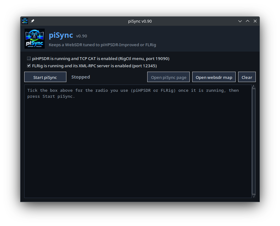
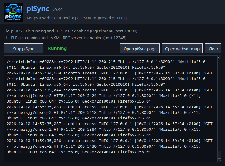
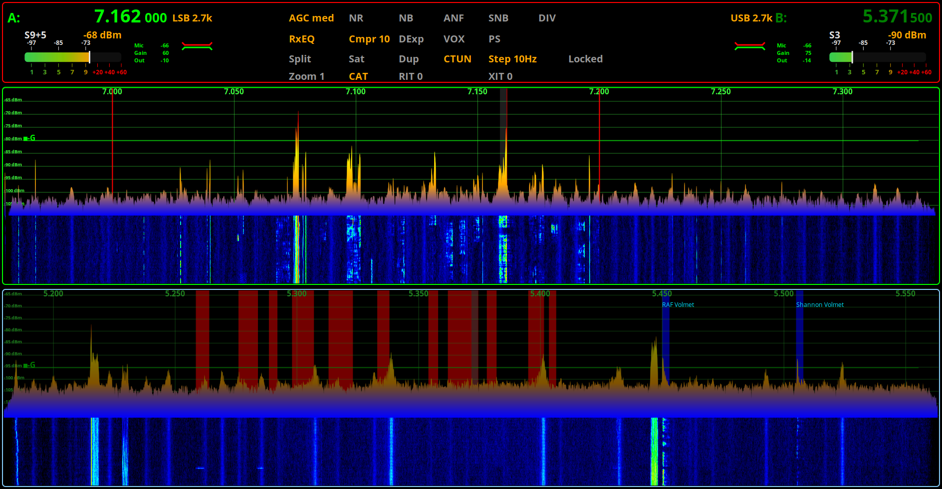
Steve (M0XVT), Alan (G1SQB) and I are pleased to announce piSync v0.9, bringing synchronised WebSDR access to Linux users running piHPSDR-Improved and now, a much wider range of transceivers through FLRig.
Windows users have enjoyed this kind of functionality through applications such as CatSync for some time. To the best of our knowledge, piSync may be the first Linux application to offer an equivalent solution for both piHPSDR-Improved and the huge range of transceivers supported by FLRig.
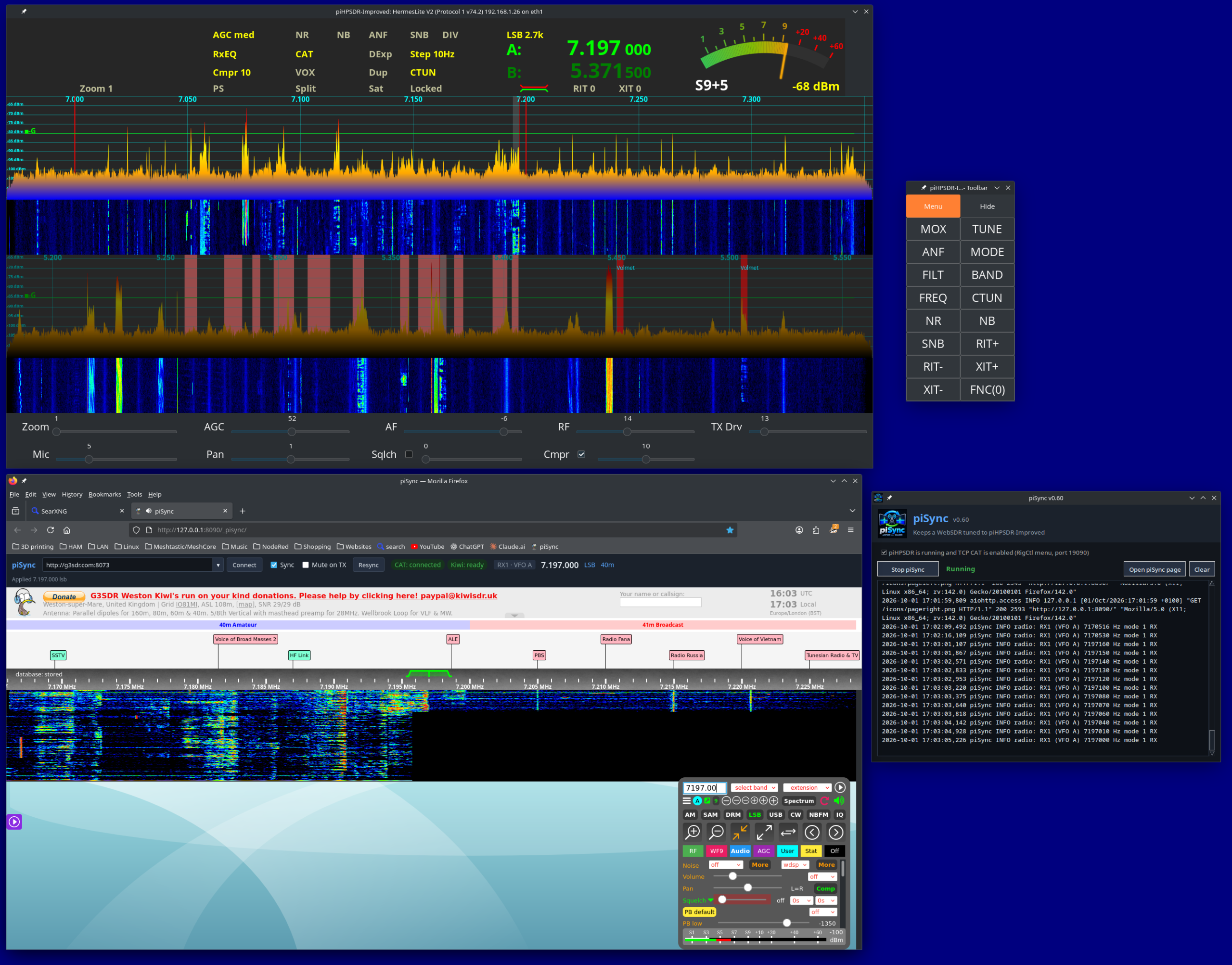
piSync v0.9 with FLRig support
Bringing New Life to Existing Radios
The addition of FLRig support is a significant step forward. piSync can follow your radio’s frequency, operating mode, active VFO and PTT status, allowing a compatible WebSDR receiver to follow you around the bands.
Whether you’re using a modern SDR or a conventional transceiver, piSync opens up new possibilities for exploring propagation and comparing signals received at different locations around the world — without replacing your existing radio.
What’s New in v0.9?
This release also introduces several improvements:
Persistent WebSDR list: Your receiver URLs are now saved on your PC and restored after restarting piSync, rather than being stored in your web browser.
WebSDR map: A new launcher button provides quick access to the WebSDR World Map.
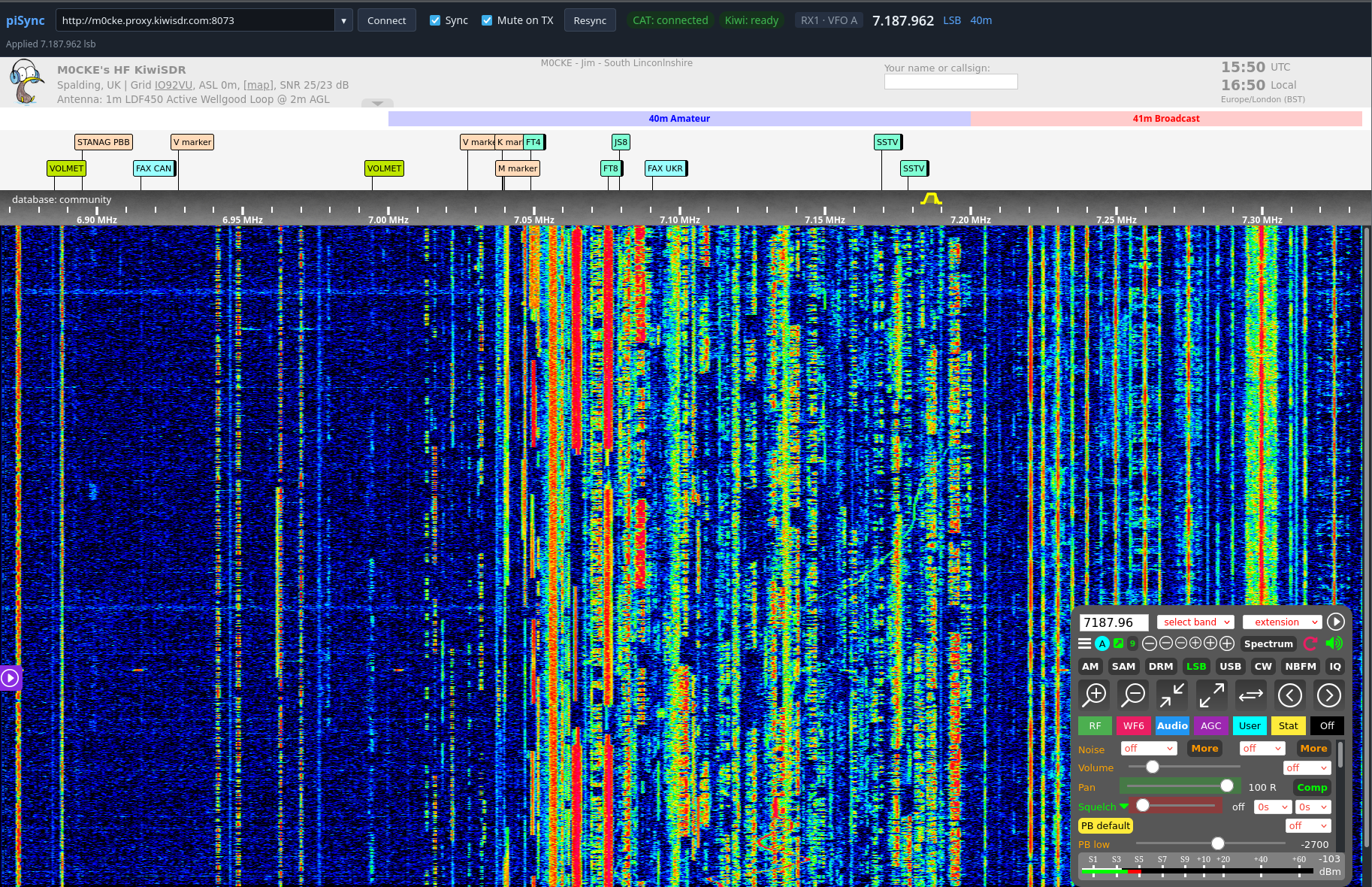
piSync v0.9 – Synchronising WebSDR’s to your Radio.
Easy Installation for Linux Users
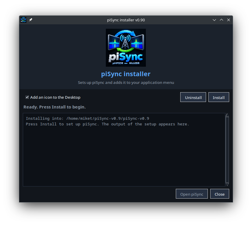
Getting started with piSync is easier than ever, thanks to its new GUI installer. Designed to simplify installation and setup, it makes piSync more accessible to everyone, including amateur radio operators making the move from Windows to Linux.
Alongside the GUI installer developed for piHPSDR-Improved, this is another step towards making Linux a practical and welcoming platform for amateur radio enthusiasts.
piSync GUI Installer – One Double Click and it’s ready to use.
We’ve Kicked the Tyres, So You Can Hit the Airwaves!
piSync has been tested on Raspberry Pi, Kubuntu (KDE Plasma), Linux Mint (Cinnamon), Debian 13 (Trixie) and Ubuntu. While we can’t test every Linux distribution, it should work on most Debian and Ubuntu based systems. We’ve done the testing so you can spend less time setting up and more time enjoying your radio!
Get piSync
If you’re a Linux-based amateur radio operator, whether using piHPSDR-Improved or a transceiver supported by FLRig, piSync is worth a look.
Synchronised WebSDR access, on Linux, using the radio you already own.
It’s been a busy week of software bug fixes and enhancements on piHPSDR-Improved and piSync.
piSync v0.9 is currently in test after we added the support for FLRig. This extends the support for many transceivers new and old along side piHPSDR-Improved and makes it useful to HAMs who aren’t using SDR’s.
piSync v0.9 with FLRig support in test
piHPSDR-Improved has also had a lot of work done to it this week with a splurge of bug fixes and enhancements being made. We decided to bring the release forward as we can then concentrate on writing the new modules to bring even more functionality to the SDR solution.
piHPSDR-Improved v2.45 in Test
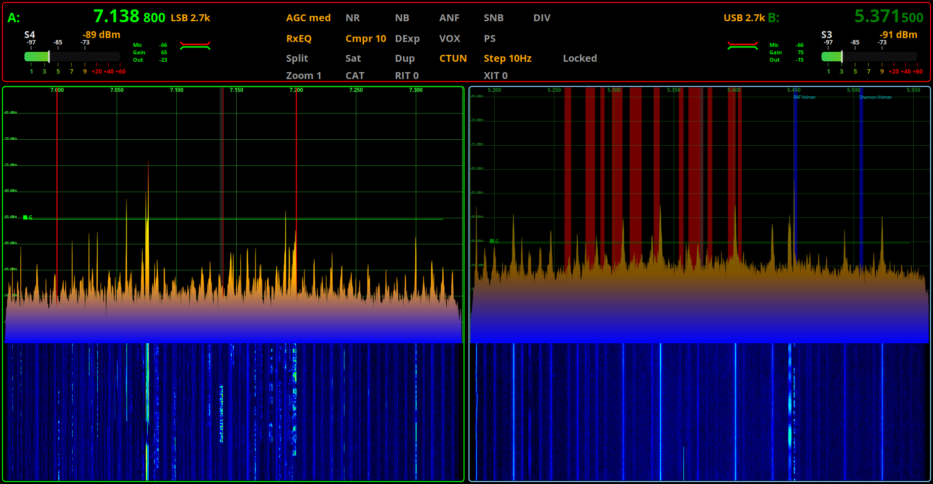
We’ve put some effort into tidying up the user interface in piHPSDR-Improved along with the new, second S Meter for VFOB. This is a really nice enhancement we’ve been wanting to do for some time but, haven’t had the time to devote to it until now.
piHPSDR-Improved v2.45 in test with Horizontally stacked RX
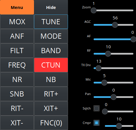
The floating toolbar has also had some upgrades and is not only looking good but, we’ve added new functionality to it as well.
piHPSDR-Improved v2.45 Floating Toolbar in Test
We’re hoping to release both of these updated software packages very soon once we’ve completed all our testing and are happy that’s it ready for release.
piHPSDR-Improved Logo from The Three Amigos Development Team
For some time now Steve (M0XVT), Alan (G1SQB) and I have been working on a version of piHPSDR to use with our Hermes Lite 2, Anan 200D, Adalm Pluto, Pluto+ and LibreSDR transceivers. The biggest problem we’ve had is the constantly changing code on github that often would stop the software from working on one device or more each time we updated and then we’d have to spend hours finding the issue and fixing it.
Eventually we got tired of this and decided to build our own stable version that doesn’t get anything from github and is made up of all the parts necessary to create a version that just works on the devices that we use on a daily basis.
Using piHPSDR on the QO-100 satellite and the HF bands across a number of very different types of hardware is a challenge in itself, especially when the devices use different protocols and only certain library sets work with certain firmware on some devices, the combinations get complicated to say the least.
To differentiate our build of piHPSDR from all the others available on the internet today we decided to call it piHPSDR-Improved.
So what is piHPSDR-Improved?
piHPSDR-Improved is a version of piHPSDR that has the fixes and enhancements in it that we’ve dreamt of having over the last couple of years. Some of the fixes are simple things like being able to detach the toolbar from the main window thus giving more space for the two panadapter/waterfall displays and have all the toolbar buttons on another screen in a floating toolbar. Other enhancements were more involved and addressed some of the most annoying issues like none of the settings for VFOB (RX2) were saved and so, every time you started the program you had to setup the RX2 all over again from scratch. These sound like simple fixes but, believe me, they’re not.
Another thing we wanted to do was make piHPSDR-Improved easy to install. Many Windows users transitioning from Windows to Linux often regret it the moment they have to use the Linux command line to install piHPSDR.
We’ve committed to having GUI installers for all the applications that we develop and release, regardless of how much extra work this entails.
It’s time installing software on Linux desktop PCs was as easy as it has been on Windows PCs for decades.
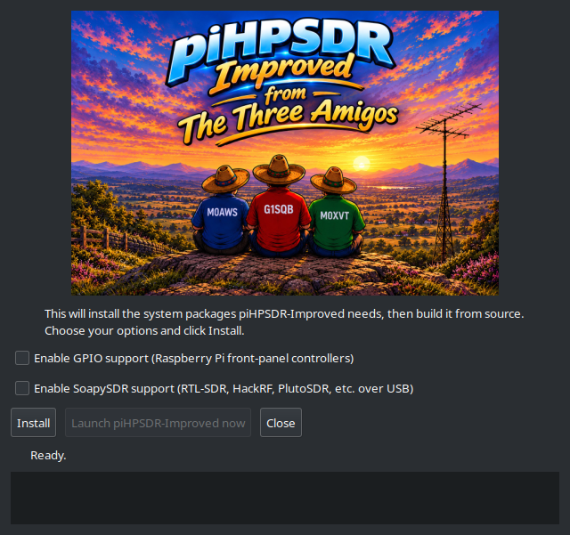
piHPSDR-Improved GUI Installer
We’ve taken a modular approach to building piHPSDR-improved. Rather than putting everything into the one application, we’re going to be releasing add on modules that will bring new functionality over time. This way we can build on a structured, stable base keeping everything operational all of the time.
The first module we’re releasing is piSync and we’ve included it in the zip file that you’ll download to install piHPSDR-Improved.
piSync Logo
piSync adds functionality to piHPSDR-Improved that Windows Thetis users have had for a long time, namely the ability to use an online WebSDR along side their own SDR transceiver and have it track the frequency, band and mode automatically. This functionality has proven to be incredibly useful when you are struggling to hear a weak DX or QRP station.
With piSync you can now use an online WebSDR receiver closer to the DX station to aid getting that QSO in the log. It’s like having another receiver in your radio that is located anywhere in the world, for free!
We believe this is a first for the Linux platform and we’re really pleased to be able to share it with the Linux community.
We’ve had great fun with piSync during testing and we think you’re all going to find it extremely useful too.
We’re also planning on adding support for FLRig in the next version of piSync so that you’ll be able to use a WebSDR with any transceiver that is supported by FLRig.
Of course it goes without saying, all of our software is Opensource. When you download and install piHPSDR-Improved or any of the new modules you will get the full source code every time and be free to do whatever you like with it. Every module will also have it’s own GUI installer, no more command line, just double click and go.
Both piHPSDR-Improved and piSync have been tested on RaspberryPi 5/500+, Linuxmint Cinnamon, Kubuntu, Debian 12 (Bookworm) and Debian 13 (Trixie) so, we’re pretty confident it’ll work on most Debian/Ubuntu based Linux distro’s on Intel/AMD PCs and the current versions of the RaspberryPi SBCs.
piHPSDR-Improved, piSync and a WebSDR running on a pi 500+
Inside the zip file you’ll find a file called README.1st, do make sure you read this before installing any of the software as it contains some important information that’ll make installation as easy as possible.
To download both piHPSDR-Improved and piSync in an easy to use zip file, just click the Download button below.
We’ve got lots of ideas for new features, modules and bug fixes (Yes there are still some bugs in there!) which we will be releasing over time. Don’t expect this to happen overnight as Steve still works full time and Alan and I are both enjoying our retirement.
This is just another facet of our hobby and we don’t like to rush things. We do like to use our radios on air, pretty much daily and so we do this software development in between all the other fun things that Amateur Radio has to offer.
To be clear and open we do use Claude Code to help with development. I go through as much of the code as I can without spending days and days just reading code. I am retired after all and have spent enough of my life professionally writing and debugging both my own code and other people’s code. We do a lot of testing on a good number of Linux distros before we even consider releasing the software to the wider world and use it on air as part of the testing process, so we’ve done as much as we can to ensure we’ve not introduced new bugs to the software. Keep in mind we do this as part of our Amateur Radio hobby and so, it needs to be fun and enjoyable.
We hope you enjoy using the software and find it useful. If you’ve got ideas for new things you’d like to see in future versions then please feel free to contact any of us via our contact details on QRZ.
UPDATE: We’ve fixed a little bug in piSync and released an updated version. You can download it from this article.
Following on from my article about my QO-100 Satellite Ground Station Complete Build, this article goes into some detail on the Node-RED section of the build and how I put together my QO-100 Satellite Ground Station Dashboard web app.
The Node-RED project has grown organically as I used the QO-100 satellite over time. Initially this started out as a simple project to synchronise the transmit and receive VFO’s so that the SDR receiver always tracked the IC-705 transmitter.
Over time I added more and more functionality until the QO-100 Ground Station Dashboard became the beast it is today.
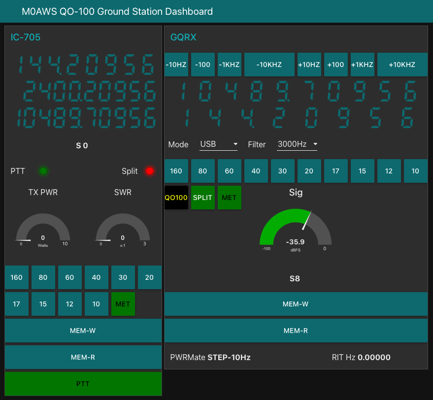
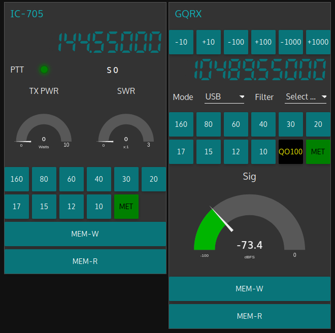
M0AWS QO-100 Ground Station Control Dashboard built using Node-RED.
Looking at the dashboard web app it looks relatively simple in that it reflects a lot of the functionality that the two radio devices already have in their own rights however, bringing this together is actually more complicated than it first appears.
Starting at the beginning I use FLRig to connect to the IC-705. The connection can be via USB or LAN/Wifi, it makes no difference. Node-RED gains CAT control of the IC-705 via XMLRPC on port 12345 to FLRig.
To control the SDR receiver I use GQRX SDR software and connect to it using RIGCTL on GQRX port 7356 from Node-RED. These two methods of connectivity work well and enables full control of the two radios.
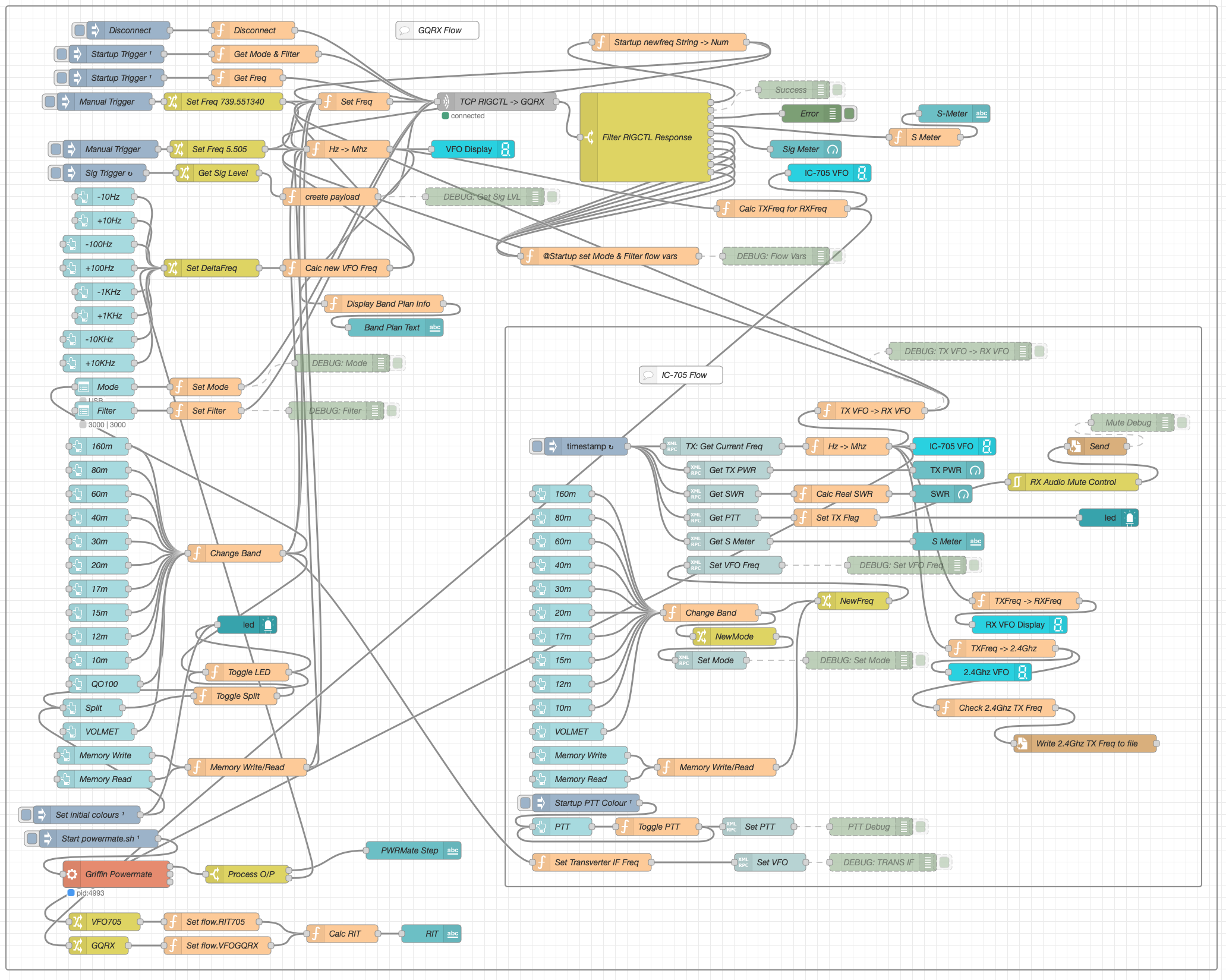
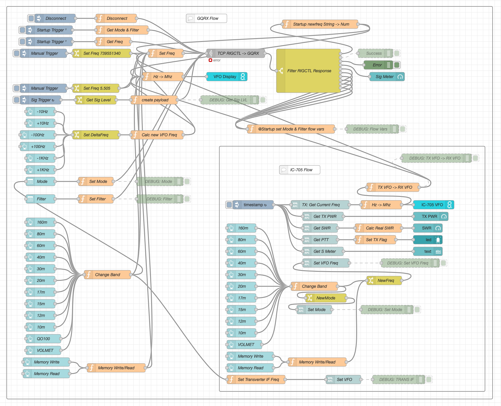
M0AWS Node-RED QO-100 Ground Station Dashboard Flow as of 12/06/24
The complete flow above looks rather daunting initially however, breaking it down into its constituent parts makes it much easier to understand.
There are two sections to the flow, the GQRX control which is the more complex of the two flows and the comparatively simple IC-705 section of the flow. These two flows could be broken down further into smaller flows and spread across multiple projects using inter-flow links however, I found it much easier from a debug point of view to have the entire flow in one Node-RED project.
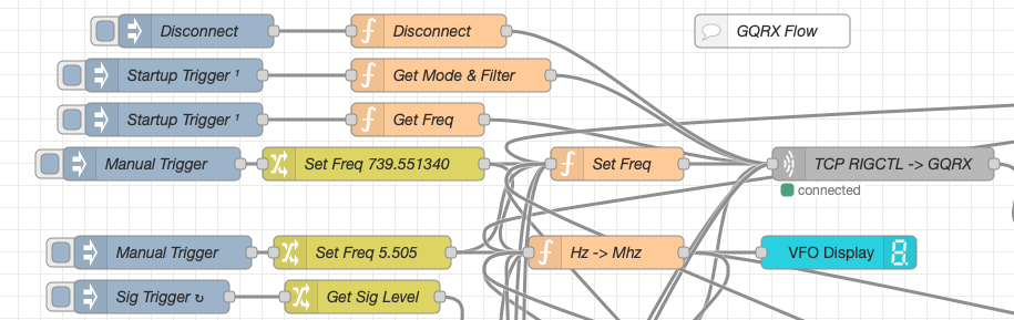
Breaking down the flow further the GQRX startup section (shown below) establishes communication with the GQRX SDR software via TCP/IP and gets the initial mode and filter settings from the SDR software. This information is then used to populate the dashboard web app.
M0AWS Node-RED QO-100 Ground Station Dashboard – GQRX Startup Flow
The startup triggers fire just once at initial startup of Node-RED so it’s important that the SDR device is plugged into the PC at boot time.
All the startup triggers feed information into the RIGCTL section of the GQRX flow. This section of the flow (shown below) passes all the commands onto the GQRX SDR software to control the SDR receiver.
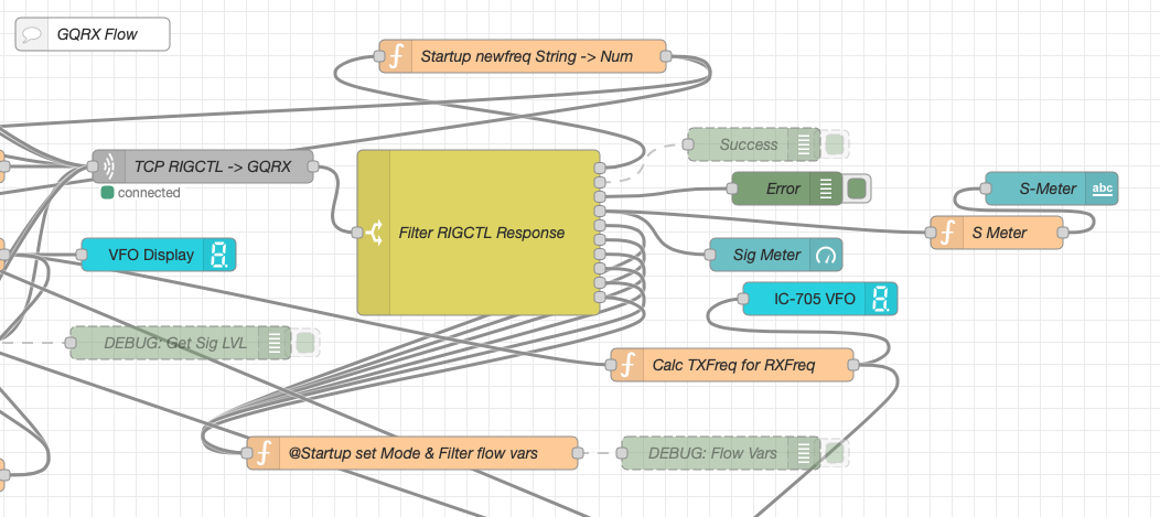
M0AWS Node-RED QO-100 Ground Station Dashboard – GQRX RIGCTL Flow
The TCP RIGCTL -> GQRX node is a standard TCP Request node that is configured to talk to the GQRX software on the defined IP Address and Port as configured in the GQRX setup. The output from this node then goes into the Filter RIGCTL Response node that processes the corresponding reply from GQRX for each message sent to it. Errors are trapped in the green Debug node and can be used for debugging.
The receive S Meter is also driven from the the output of the Filter RIGCTL Response node and passed onto the S Meter function for formatting before being passed through to the actual gauge on the dashboard.
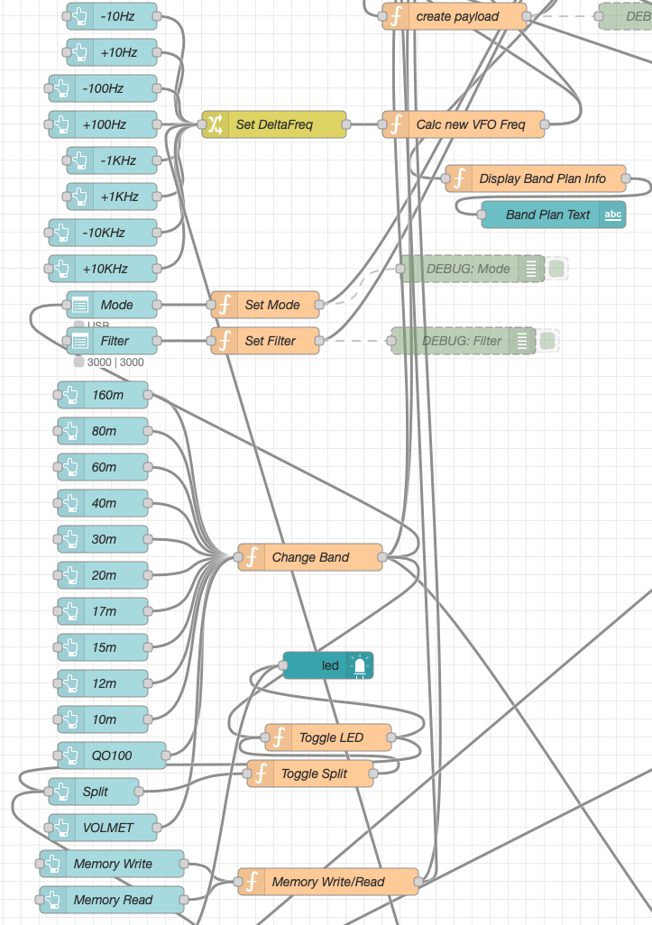
Continuing down the left hand side of the flow we move into the section where all the GQRX controls are defined.
M0AWS Node-RED QO-100 Ground Station Dashboard – GQRX Controls Flow
In this section we have the VFO step buttons that move the VFO up/down in steps of 10Hz to 10Khz. Each button press generates a value that is passed onto the Set DeltaFreq change node and then on to the Calc new VFO Freq function. From here the new VFO frequency is stored and passed onto the communications channel to send the new VFO frequency to the GQRX software.
The Mode and Filter nodes are simple drop down menus with predefined values that are used to change the mode and receive filter width of the SDR receiver.
Below are the HAM band selector buttons, each of these will use a similar process as detailed above to change the VFO frequency to a preset value on each of the HAM HF Bands.
The QO-100 button puts the transmit and receive VFO’s into synchro-mode so that the receive VFO follows the transmit VFO. It also sets the correct frequency in the 739Mhz band for the downlink from the LNB in GQRX SDR software and sets the IC-705 to the correct frequency in the 2m VHF HAM band to drive the 2.4Ghz up-converter.
The Split button allows the receive VFO to be moved away from the transmit VFO for split operation when in QO-100 mode. This allows for the receive VFO to be moved away so that you can RIT into slightly off frequency stations or to work split when working DXpedition stations.
The bottom two Memory buttons allow you to store the current receive frequency into a memory for later recall.
At the top right of this section of the flow there is a Display Band Plan Info function, this displays the band plan information for the QO-100 satellite in a small display field on the Dashboard as you tune across the transponder. Currently it only displays information for the satellite, at some point in the future I will add the necessary code to display band plan information for the HF bands too.
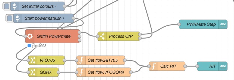
The final section of the GQRX flow (shown below) sets the initial button colours and starts the Powermate USB VFO knob flow. I’ve already written a detailed article on how this works here but, for completeness it is triggered a few seconds after startup (to allow the USB device to be found) and then starts the BASH script that is used to communicate with the USB device. The output of this is processed and passed back into the VFO control part of the flow so that the receive VFO can be manually altered when in split mode or in non-QO-100 mode.
M0AWS Node-RED QO-100 Ground Station Dashboard – Powermate VFO Flow
The bottom flows in the image above set some flow variables that are used throughout the flow and then calculates and sets the RIT value on the dashboard display.
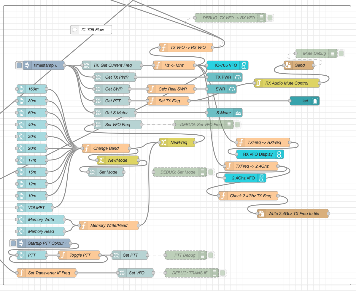
The final section of the flow is the IC-705 control flow. This is a relatively simple flow that is used to both send and receive data to/from the IC-705, process it and pass it on to the other parts of the flow as required.
M0AWS Node-RED QO-100 Ground Station Dashboard – IC-705 Control Flow
The IC-705 flow is started via the timestamp trigger at the top left. This node is nothing more than a trigger that fires every 0.5 seconds so that the dashboard display is updated in near realtime. The flow is pretty self explanatory, in that it collects the current frequency, transmit power, SWR reading, PTT on/off status and S Meter reading each time it is triggered. This information is then processed and used to keep the dashboard display up to date and to provide VFO tracking information to the GQRX receive flow.
On the left are the buttons to change band on the IC-705 along with a button to tune to the VOLEMT on the 60m band. Once again there two memory buttons to save and recall the IC-705 VFO frequency.
The Startup PTT Colour trigger node sets the PTT button to green on startup. The PTT button changes to red during transmit and is controlled via the Toggle PTT function.
At the very bottom of the flow is the set transverter IF Freq function, this sets the IC-705 to a preselected frequency in the 2m HAM band when the dashboard is switched into QO-100 mode by pressing the QO-100 button.
On the right of the flow there is a standard file write node that writes the 2.4Ghz QO-100 uplink frequency each time it changes into a file that is used by my own logging software to add the uplink frequency into my log entries automatically. (Yes I wrote my own logging software!)
The RX Audio Mute Control filter node is used to reduce the receive volume during transmit when in QO-100 full duplex mode otherwise, the operator can get tongue tied hearing their own voice 250ms after they’ve spoken coming back from the satellite. This uses the pulse audio system found on the Linux platform. The audio is reduced to a level whereby it makes it much easier to talk but, you can still hear enough of your audio to ensure that you have a good, clean signal on the satellite.
As I said at the beginning of this article, this flow has grown organically over the last 12 months and has been a fun project to put together. I’ve had many people ask me how I have created the dashboard and whether they could do the same for their ground station. The simple answer is yes, you can use this flow with any kind of radio as long as it has the ability to be controlled via CAT/USB or TCP/IP using XMLRPC or RIGCTL.
To this end I include below an export of the complete flow that can be imported into your own Node-RED flow editor. You may need to make changes to it for it to work with your radio/SDR but, it shouldn’t take too much to complete. If like me you are using an IC-705 and any kind of SDR controlled by GQRX SDR software then it’s ready to go without any changes at all.
I’ve now completed the GQRX Receive and Icom IC-705 Transmit dashboard in Node Red. It was a fun project to put together and needed some javascript coding to get the functionality I wanted but, I got there in the end.
M0AWS QO-100 GQRX/IC-705 control dashboard
The dashboard looks fairly simple but, there is a lot behind the scenes to get it to this stage.
On the left is the Icom IC-705 transmit control panel. It shows the transmit frequency, power output and SWR reading. The SWR is so that I can check that the input into the 2.4Ghz transverter doesn’t have any connectivity issues. The “S0” will actually display the S Meter reading when the IC-705 is being used as a normal transceiver rather than being in QO-100 Duplex mode as shown above where the GQRX app and Funcube Dongle SDR are being used as the receiver.
The GQRX side of the dashboard shows the downlink frequency which tracks the uplink frequency of the VFO on the IC-705. This will ensure that the Funcube Dongle Pro+ SDR receiver will always be on the correct downlink frequency relative to the uplink frequency, thus I should always be able to hear my own signal coming from the QO-100 satellite.
Once taken out of QO-100 mode the two radios can be used independently on any of the HAM bands and can be switched using the buttons on the dashboard.
I also coded in a simple memory facility where a frequency can be stored in Node Red and recalled later on both the transmit and receive sides.
Looking at the dashboard it all looks simple and straight forward however, if you look at the Node Red flow it becomes obvious that this isn’t the case.
QO-100 Dashboard Flow in the Node Red Editor (Click for larger image)
There’s a lot to the flow to get the information from the receiver and transmitter so that it can be presented on the dashboard. There’s also some code to convert between Rigctl protocol used by the GQRX application and XMLRPC used by the IC-705 via FLRig and WFview. I had to also code around a bug in the Node Red XMLRPC node whereby you have to add 0.1 onto the VFO frequency for it to be passed onto the radio otherwise the information is never sent. This was a real pain of a bug to find but, with a little experimentation I found the problem and managed to code around it. The strange thing about this is that the 0.1 added onto the frequency isn’t actually passed onto the radio via the XMLRPC node, it just has to have that on input otherwise it doesn’t work at all. A very strange bug and hopefully one that will be fixed by the node developer in future releases.
All that is left to do now is add the temperature sensors dashboard to complete the dashboard. These haven’t arrived yet and so I’ve not been able to create the necessary flow to collect the data from them.
Hopefully this coming week the weather will improve and I’ll start getting the dish antenna up and the get the receive side working.
UPDATE: Further development of my QO-100 Dashboard has taken place, you can read all about it here.
I’ve been chasing the DX on the HF bands using FT8 for a while now and I have to say it’s been very successful however, it does get rather boring after a while just exchanging SNR reports and nothing else. I noticed that my time spent in the shack was getting less and less, not a good sign after all the work I’d put into building the new radio shack.
Since there’s not a lot of CW on the bands these days (everyone is on FT8) I thought I’d give JS8CALL a go.
Initially I started with trying to get JS8CALL working on my Kubuntu PC to my Icom IC-705 wirelessly. This turned out not to be as straight forward as I’d hoped but, I persevered.
I found that to communicate with the IC-705 via WFview wirelessly I needed to use FLRig as a go between. I installed FLRig from the Ubuntu repo’s only to find it’s an old version that doesn’t have support for the IC-705. Downloading the IC-705.xml file didn’t help either so I uninstalled it and headed to the source forge website to grab the source code for the latest version of FLRig.
Once I had the right development libraries installed compiling the code was easy enough and I soon had FLRig talking to the IC-705 via WFview wirelessly from my Kubuntu PC.
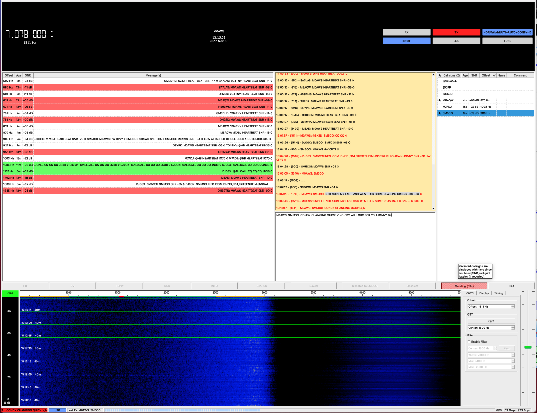
My first JS8 QSO was with Jonny, SM5COI in Sweden on the 20m band, using just 2.5w I had a very reliable link from my 20m band EFHW vertical antenna to his 20m band yagi antenna.
I also worked GM0DHD/P via OH8XAT using the relay capability built into JS8CALL, it works incredibly well and allows you to work the stations that you cannot hear directly, very useful!
Later in the morning Jonny, SM5COI emailed me asking for a sked on the 40m band later in the afternoon, of course I agreed and decided that I’d also get my MacBook Pro setup with JS8CALL so I could give my Yaesu FTDX10 a spin on JS8 mode.
Installing and configuring JS8CALL on my MacBook Pro was much easier and I had it fully operational in minutes.
The sked went well on 40m and it was good to get Jonny on another band.
With 3 JS8 QSOs in the log it’s great to be using a digital mode again that allows you to have a good chat with other radio HAMs around the world. I think this may become my preferred digital mode going forward.
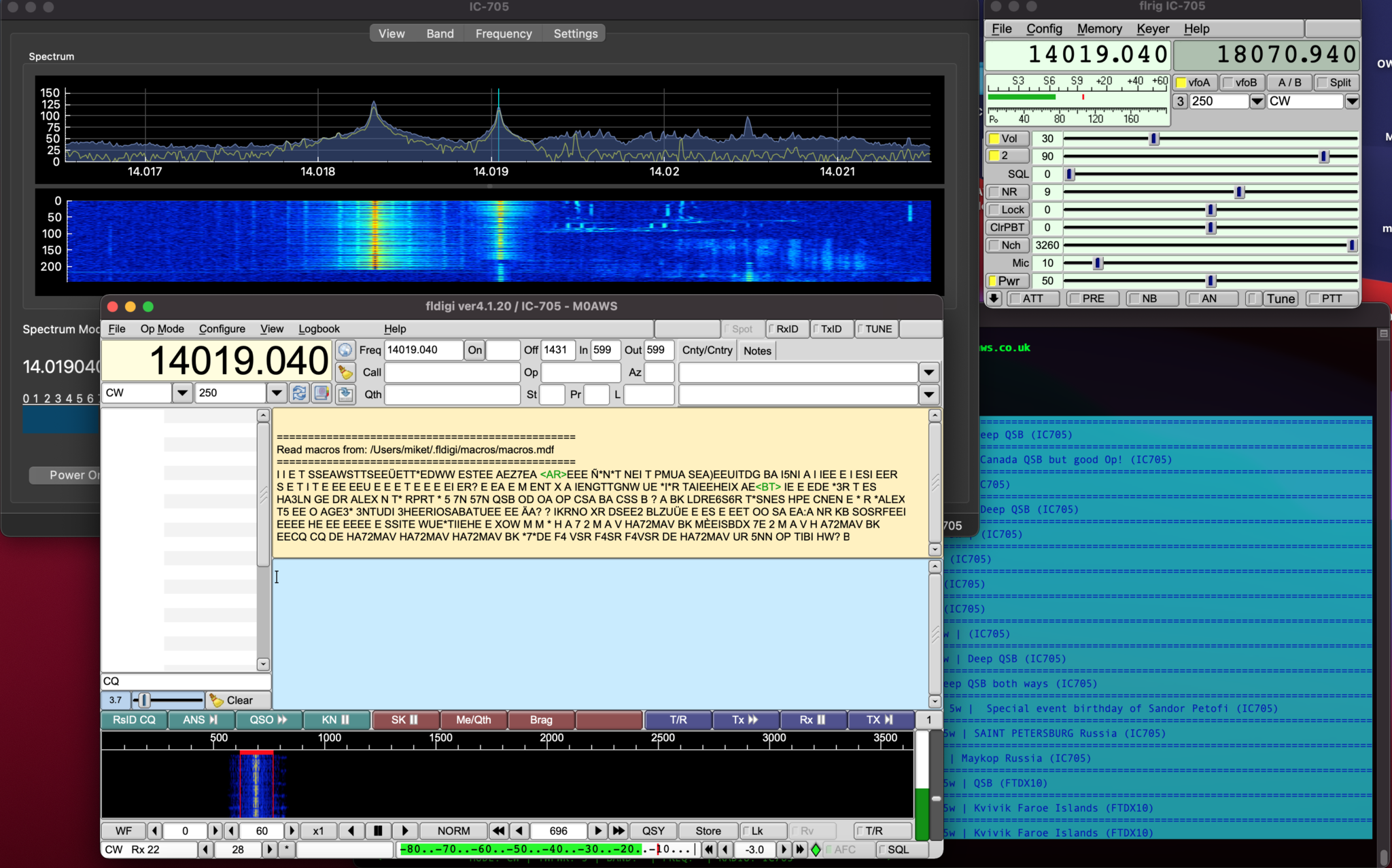
Screenshot showing WFView, FLRig and FLDigi all working wirelessly with my IC-705
In my “IC-705 Going Wireless with Apple Mac Computers” article I came across an issue whereby I couldn’t enter the correct path into FLRig to get the application to talk to WFView for CAT control of the IC-705 radio. I’m glad to say that I have now resolved this issue and detail it below.
Upon further inspection it appears that WFView uses a different /dev/ttys00x port each time it is started. It seems to round robin on ports 001 to 006. It’s quite clever in that it doesn’t actually directly use the port, each time the WFView app is started it creates a softlink to the next port after the one it last used.
The softlink is created with the same name each time the app is started but, it just points to the next /dev/ttys00x port available.
In my WFView setup I selected the first virtual serial port in the drop down list and so this soft link (AKA Symbolic link) gets created each time the WFView app is started.
Above soft link used by WFView (Replace “username” with your username)
The problem with FLRig is that it won’t allow you to type in this path to the serial port field, it only has a drop down list that doesn’t include this path.
The way around this is to edit the settings file IC-705.prefs in the .flrig folder in your home directory and manually enter the path to the correct field.
In the file there is an entry that starts with xcvr_serial_port: you just need to add the long path from WFView after the colon on the same line as shown below.
NOTE: Change username to your username as shown in the virtual serial port field in the WFView settings tab.
Once you’ve edited the file, save and close it and then start WFView and let it connect to the IC705 and then start FLRig. You’ll find it now connects to WFView directly and gains CAT control of the radio without issue.
You shouldn’t need to ever edit the IC-705.prefs file again as the settings are stored permanently. It should just work each time you start the FLRig app.
To get the frequency display on FLDigi just go into settings and switch on the FLRig CAT control, it will get all the data from FLRig and present it as shown in the screenshot above.
More soon …
We use cookies to ensure that we give you the best experience on our website. If you continue to use this site we will assume that you are happy with it.