Building MB7IBW 2m AllStarLink Internet Gateway

I’ve recently built another AllStarLink node to compliment my personal 70cm band SHARI node as I thought since I have a full duplex dual band handheld it would be great to have another node that I could connect to FreeStar or HUBNet at the same time as monitoring the Matrix node.

Rather than build another personal node I decided this time I would build a public node, obtain a callsign from the RSGB and make it available to the HAM’s locally on the 2m band.

This would make it possible for me to monitor both nodes at the same time using my Wouxun KG-UV9K full duplex dual band handheld whilst providing the local HAM community with access to the AllStarLink network.

Initially I thought I may be able to use my old Retevis RT85 handheld and AIOC board for the 2m node but, after a little testing it soon became apparent that it overheats during long overs (which are common on AllStarLink) and so, I needed to find another solution.
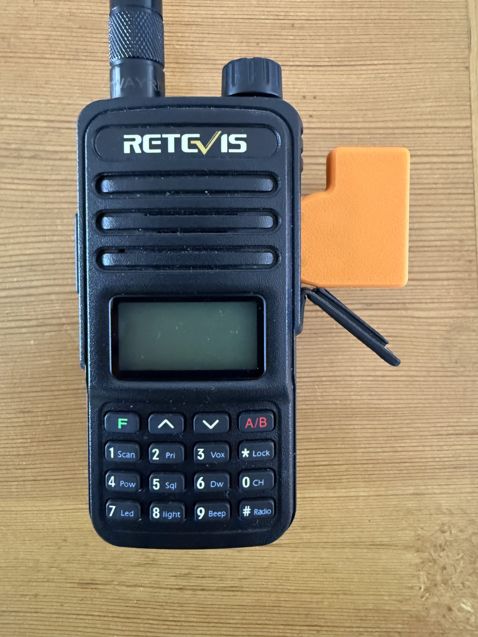
AIOC connected to the Retevis RT85.

Chatting about this in the main Matrix HAM Radio room Steve, M0XVT sent me a message saying he had an old Key KM-4000 converted PMR radio that had been reprogrammed for the 2m band that he was looking to sell and that it might be ideal for the new node. Wasting no time, we came to an agreement and I was soon the proud owner of a converted PMR transceiver.
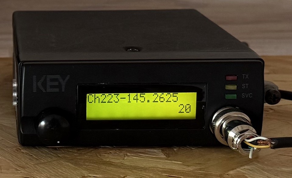
Key KM4000 2m Band PMR Radio

The KM4000 transceiver has a standard output of 15w, 10w more than I needed for the gateway and so I had to reduce the output. A quick search on the internet and I found the Thames Valley Repeater Group website that had all the information required to turn down the output.

I also had to reprogramme channel 1 to the frequency and CTCSS tone allocated to me by the RSGB so that in the event of a power outage when the radio came back on it automatically jumps to channel 1 which would be correctly setup for operation.

Unfortunately the software for programming the radio is only available for windows and so I had to build a virtual machine running windows 10 to be able to reprogramme the radio.

Once this was done I rewired the AIOC USB audio device to work with the KM4000 radio and built the AllStarLink node on a spare RaspberryPi 4.

For an antenna I made a simple end fed vertical dipole from some RG58 coax and mounted it 8m up on one of my Spiderpoles in the garden. Running a coax feed out to the antenna I did some tests into the Parrot to get the audio levels setup and checked that the DTMF codes were interpreted correctly and that the node switched connections without error.
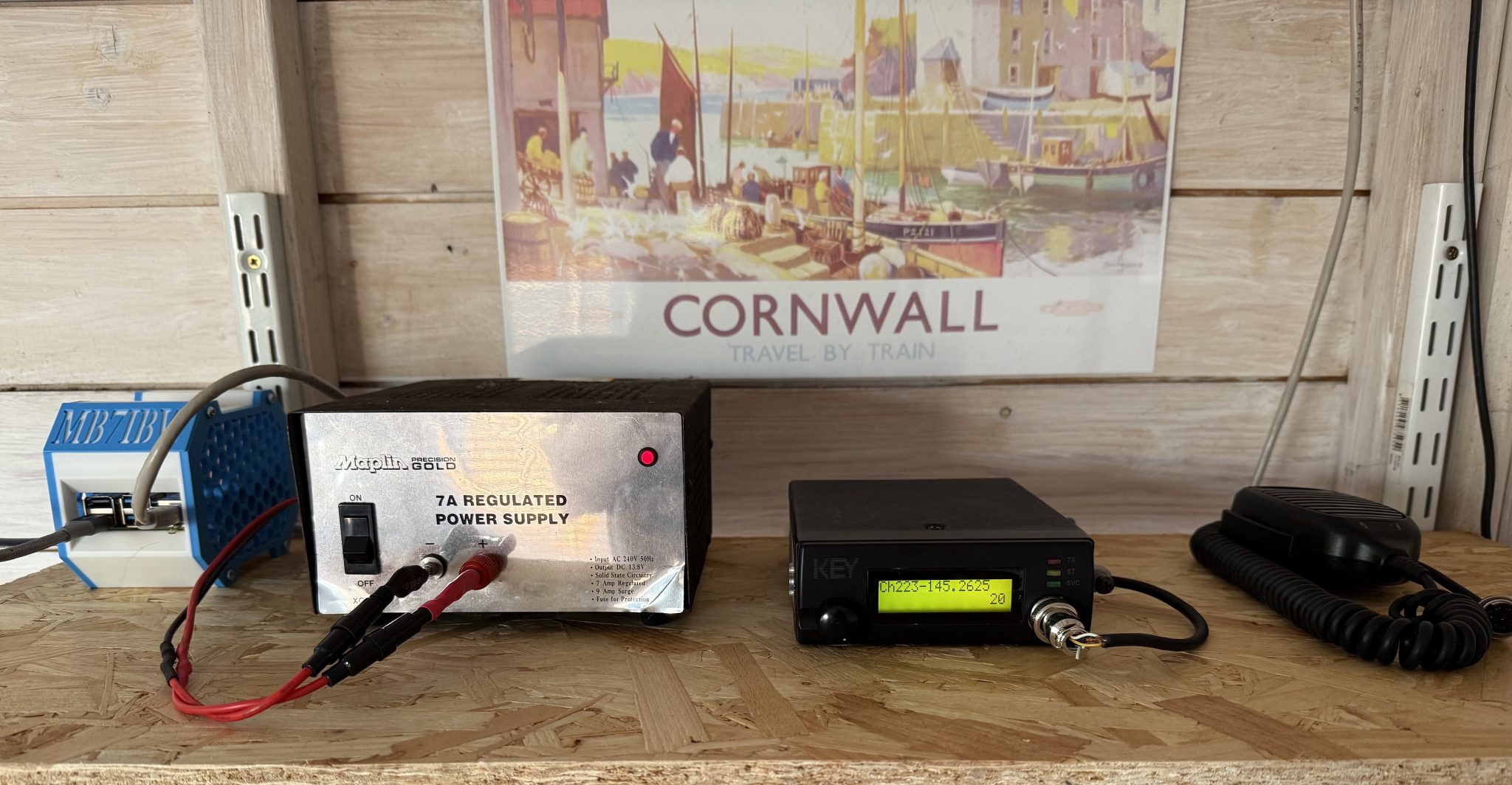
MB7IBW Internet Gateway hardware at the M0AWS QTH

Once this was done I had a few test conversations with stations on the Matrix node and FreeStar to ensure all was fine and then set the gateway status to “Operational” on the RSGB website.

This worked fine for a while with myself and some local stations using the node regularly but, then the hot weather arrived and things started to overheat. The transceiver was getting incredibly hot in the 30c+ summer temperatures and the power supply was also running extremely hot and so I decided to add some cooling.

Cooling the PSU was simple, it has a perforated top panel to which I strapped a cooling fan. This worked great and brought the temperature of the PSU down considerably.

The radio wasn’t so easy to cool. It has a solid case cover top and bottom and so cooling wasn’t going to be a simple affair.

I decided to remove the covers and drill some holes into them to allow airflow through the unit and strapped a fan to the top cover to pull the hot air out. This worked well however, on both transmit and receive I now had a warbling sound on the audio that was caused by the motor of the fan when powered up.

I found that lifting the fan up away from the case of the radio the warbling audio disappeared and things were back to normal and so, I decided to design a cooling tube to fit to the top of the radio to allow full airflow from the fan but, with the fan raised up away from the radio to resolve the audio problem.

Jumping into my CAD software I quickly designed a cooling tower to fit on the top of the radio that would allow the fan to sit far enough away from the radio so as to not affect the audio whilst at the same time pulling the hot air out of the radio and drawing cooler air in through the bottom of the case.

I sent the design through to my Bambu Lab A1 Combo 3D printer and set the print job running.
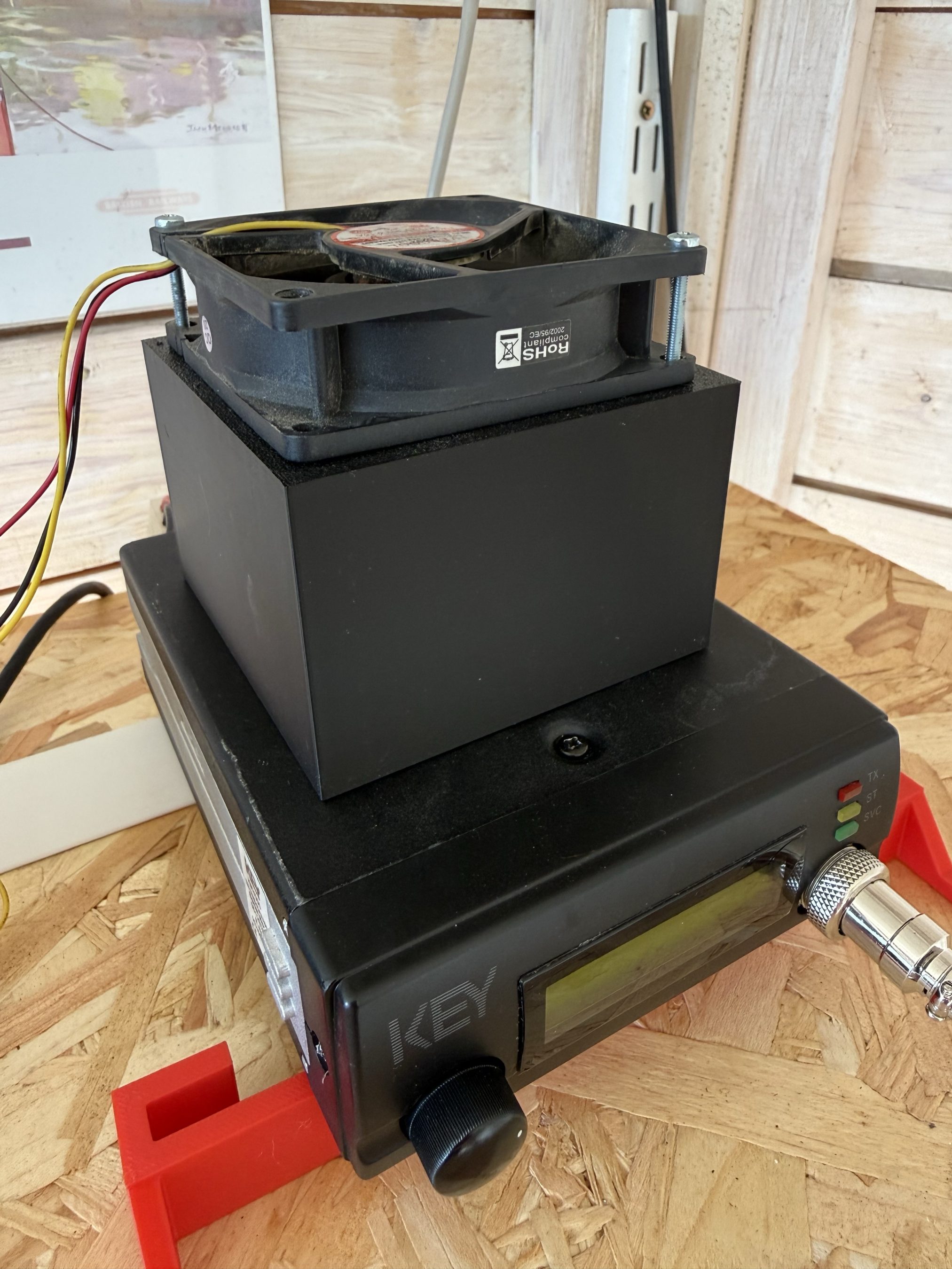
Key KM4000 Cooler
Key KM4000 Cooler

The cooler worked great with the radio staying cool to the touch and no longer overheating and reducing O/P power.

It’s amazing how much dust and dirt is in the air from all the farming activities going on at the end of our garden and how much of it is sucked in by the cooling fan. Regular cleaning is a must!

The MB7IBW Internet Gateway has been on air since mid June 2026 and has worked well. It spends most of its time connected to either FreeStar or HUBNet with connections to the Matrix Node when we have our nets.

Details on Frequency, CTCSS etc can be found under the MB7IBW menu above.

Sadly the initial interest from local HAMs has now wained and I am mostly the only user of the gateway. I was hoping more people would use it and bring some life to the 2m band, I guess time will tell.

It’s been a fun project and was interesting to go through the callsign allocation process with the RSGB representative. It was much easier than I thought it would be.

I now have all the parts to build another Internet Gateway for the 4m band. Hopefully that may attract some more interest. It’s certainly worth a try!

More soon …

1946 Philips 170A-15 RadioBerry Receiver Project

Back in January 2025 I wrote an article about a little RadioBerry Project I’d started that was based around a very old Philips 170A-15 receiver from 1946.

The idea of the project was to build a nice shortwave receiver for the radio shack based around the RadioBerry HAT on a RaspberryPi 4 housed in a vintage receiver cabinet.

The project has taken longer than I imagined due to getting side-tracked by other projects that I already had ongoing.

1946 Philips 170A-15 Shortwave Receiver Internal View

With the original internals removed there’s plenty of room inside for the RadioBerry, RaspberryPi 4 and the small 15w audio amplifier. The audio is delivered via a pair of Celestion speakers that I had that were originally part of an old surround sound TV system.

Power distribution is achieved very simply using a multi-plug adapter that also has USB A connections in it. The whole thing is then powered via one 240v mains cable.

The screen fits over the original opening for the glass tuning display and is held in place by two mounting screws on the rear of the LCD panel.

I purchased some new speaker grill cloth from Amazon and remade the speaker grill front with cut outs for the speakers. It looks really tidy and matches the rest of the bakelite cabinet nicely.

1946 Philips 170A-15 Shortwave Receiver RadioBerry HAT on RaspberryPi 4

To finish the project off I need to purchase 3 rotary encoders so that I can have a VFO knob and two more knobs for other things (to be determined). The Volume control is already in place with the original knob fitted to it. It will be nice to complete the 4 knob line up.

1946 Philips 170A-15 Shortwave Receiver Rear Panel

I had to make a couple of fittings top and bottom to hold the original rear panel in place but, it worked out just fine and I only had to fit an SO239 antenna connector and ethernet RJ45 port so that it can be connected to my local LAN.

Receiving radio Caroline on 648Khz

The audio quality from the little RadioBerry and 15w amp is pretty good. With the speakers hidden nicely behind the refurbished speaker grill the project looks quite tidy!

It also makes a great receiver for the HAM bands with it’s coverage of 100Khz to 30Mhz.

The DL1YCF Enhanced fork of PiHPSDR works really well on the touchscreen and provides a modern control interface to the RadioBerry HAT.

Listening to the 20m HAM Band

I’ll drop a final article once I have purchased the 3 rotary encoders to fill the 3 remaining holes in the front of the cabinet.

More soon …

Hermes Lite 2 and Xiegu XPA125B Auto Band Switching

Since I’ve had my Hermes Lite 2 (HL2) and Xiegu XPA125B amplifier combo I’ve had to manually change the band setting on the amp as I never purchased the HL2 I/O board when I initially purchased the kit.

At the time I didn’t think I would need it but, changing band manually on the amp (and sometimes forgetting causing tuning issues) is a nuisance and so I put my hand in my pocket once again and ordered the I/O board for the HL2.

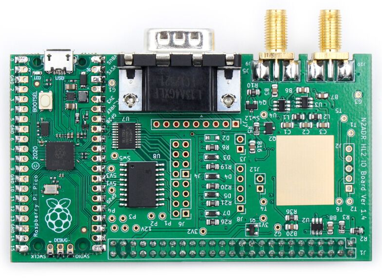
Hermes Lite 2 I/O Board

The HL2 I/O board is a small RaspberryPi Pico controlled device that can be used for a multitude of functions depending on the software loaded. Many people are writing their own software for the Pico to do things like control transverters, remote antenna switches, amplifiers and just about anything else you can think of. It’s a really versatile little add on board for the HL2.

The I/O board arrived after about 10 days from Makerfabs, all nicely packaged as always. Unfortunately due to Christmas, New year and other priorities it’s sat in the box since it arrived.

A couple of days ago I finally got round to getting it out of the box and set about configuring it to control the Xiegu amp.

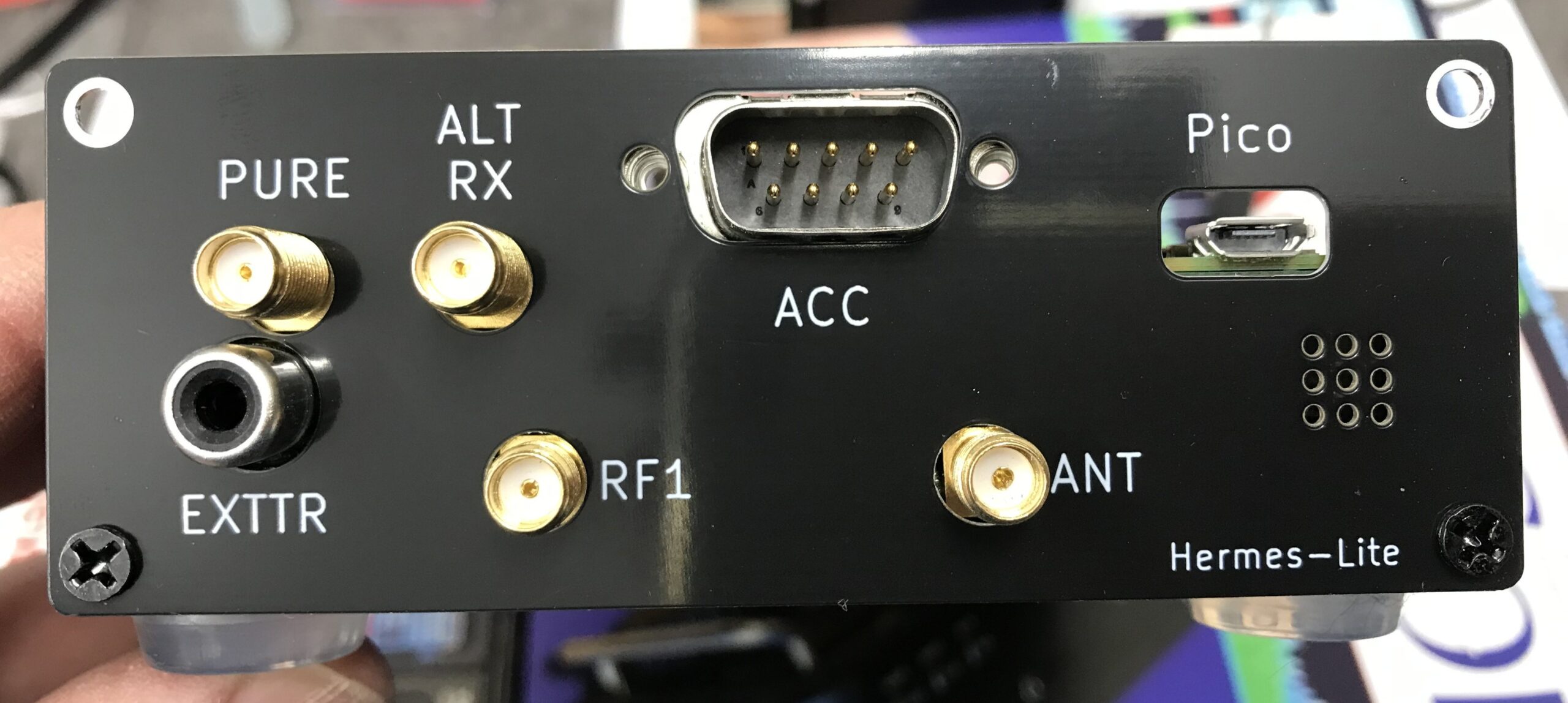
The Xiegu amp needs three connections from the I/O board. They are PTT, Band Switching Voltage and Ground. These are easily accessed from the I/O board via 3 jumper wires to connect to the DB9 connector on the rear of the board.

The other thing that is required is some software for the RaspberryPi Pico to control the whole process. Steve, M0XVT has kindly supplied me with a copy of the software.

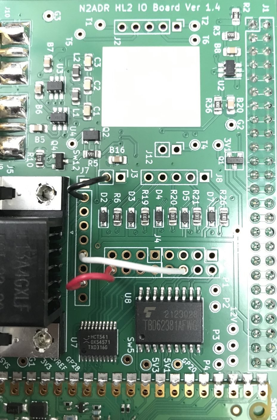
Soldering the jumpers from the relevant points on the circuit board to the DB9 connector was pretty straight forward. You can use any of the pins on the DB9 connector that you like as from the factory the DB9 connector isn’t connected to anything. I decided to use pins 2, 6 and 8 and so will refer to those pins from this point forward.

HL2 I/O Board Jumpers

I used a different colour for each of the jumpers so that I knew which jumper was for which connection. The colours used also match the colours of the wire in the old RS232 serial lead that I cannibalized to make the connection between the I/O board and the amp thus making it easy to ensure continuity.

The colours are as follows:

Black Jumper - Ground - Pin 2 on DB9 Connector
White Jumper - PTT - Pin 6 on DB9 Connector
Red Jumper   - Band Control - Pin 8 on DB9 Connector

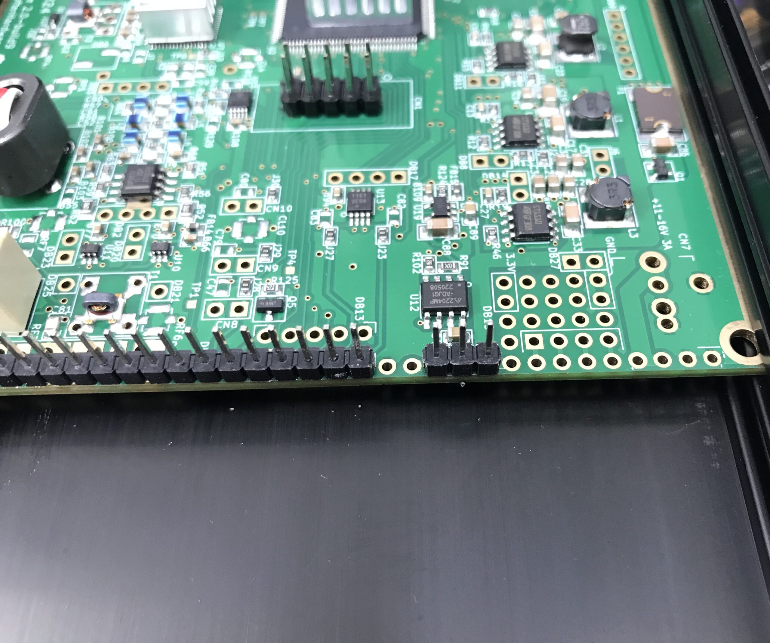
The I/O board gets its power feed directly from the HL2 main board however, the 3 pins it needs to connect to don’t have any headers in place and so, it’s necessary to solder a short row of 3 header pins onto the HL2 main board.

I found the easiest way to do this was to put the 3 header pins into the correct position and then use the HL2 to N2ADR filter board connector to hold them in place whilst soldering. This worked perfectly and I soon had the header pins soldered onto the main board.

Extra 3 header pins soldered to the main HL2 board

It’s important to note that the 3 extra header pins need to be placed 2 holes away from existing header pins as shown above. Take care to get these pins in the right position so as not to cause any damage to the 3 circuit boards once all are connected and powered up.

Note: The HL2 main board must be removed from the case to solder the extra 3 header pins in place. Take care to ensure the correct fitting of the PA heatsink when when refitting the HL2 main board into the case.

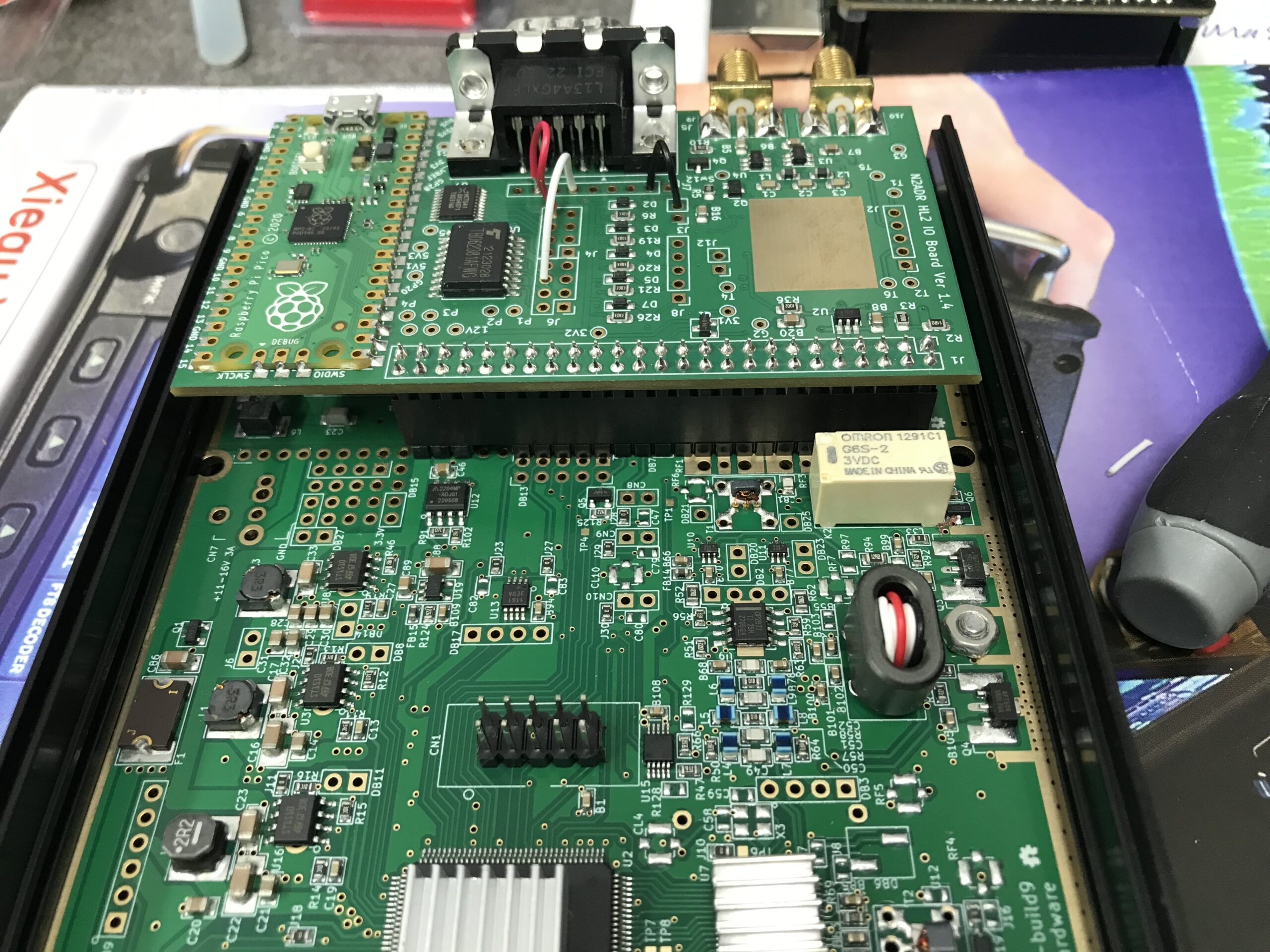
At this point I refitted the N2ADR Filter board back into the HL2 case so that the two sets of header pins aligned correctly ready for the placement of the new I/O board that would connect all 3 circuit boards together.

Preparing the N2ADR Filter board for reconnection

Once the filter board was in place I fitted the new I/O board taking care to ensure all pins aligned with the socket and then gently pushed it home.

Close up of the HL2 I/O board fitted to the main HL2 board and N2ADR Filter board

The close up of the I/O board connector above shows how the extra 3 header pins connect to the last 3 sockets in the I/O board connector. It’s a snug fit with the N2ADR filter board below it.

View of the fitted HL2 I/O board from above

Before the HL2 case can be put back together it’s necessary to load the software onto the RaspberryPi Pico (top left in photo above) that controls the I/O board.

This is accomplished by pressing the tiny button on the Pico whilst connecting a USB lead to the USB socket on the board that had already been plugged into my PC. Once connected the Pico appeared as a USB drive on my Kubuntu Linux desktop. All I then had to do was to copy the software file onto the drive. Once the software file is on the drive the Pico will reboot automatically and the little LED on the board will start to flash to show it has booted successfully. At this point I could safely unplug the USB cable.

The software for the RaspberryPi Pico is available for download below.


The I/O board comes with a new back panel for the HL2 to accommodate the extra connectors on the rear. Refit the top of the HL2 case and then attach the new rear panel using the original 4 counter sunk screws.

Supplied HL2 I/O board replacement rear panel fitted to the HL2 case
Supplied HL2 I/O board replacement rear panel fitted to the case

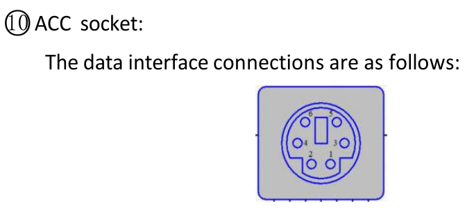
The final part of this project is to make the lead that will go from the HL2 rear DB9 ACC connector to the Xiegu XPA125B mini din ACC socket.

For this you will need a 6 pin mini din plug (AKA PS2 plug), (these are readily available on Amazon) and an old fashioned DB9 female connector from the days of RS232 serial leads..

The connections are as follows:

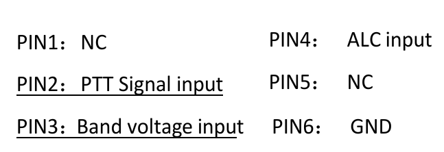
DB9 Pin 2 (BLACK) to Mini Din Pin 6 (GND)
DB9 Pin 6 (WHITE) to mini Din Pin 2 (PTT)
DB9 Pin 8 (RED) to Mini Din Pin 3 (Band Switching Voltage)

Below are a couple of screenshots from the Xiegu XPA125B user manual showing the Mini Din pin layout and the data interface connections for the amplifier.

Xiegu XPA125B Amplifier ACC Interface Connections
Xiegu XPA125B Amplifier ACC Connector Pin Information

Before I connected the lead to the two devices, I tested the end-to-end continuity of the lead to ensure all pins were correctly connected and that there were no shorts between any of the pins.

It’s important that the wires are connected to the correct pins on each end of the lead. Failure to ensure correct connection could cause damage to your HL2 and/or amplifier.

Once the lead had been tested, I connected it to both the Hermes Lite 2 and the Xiegu XPA125B amplifier. I also had to switch the amplifier band switching to AUTO.

Now when I change band on my HL2 in the PiHPSDR software the amplifier also changes band at the same time keeping the two devices in sync. No more manual band changing for me!

I hope this article is of use to other Hermes Lite 2 users who have purchased the Xiegu XPA125B but, have yet to setup auto band switching between the two devices.

Thanks to Steve, M0XVT for all the jumper information and the RaspberryPi Pico Software to get this all working.

UPDATE:
The RaspberryPi Pico software originally came from Ramon, KP4RX. More information can found in this Google Groups article where he released the binary into the wild.

A full table of I/O resources available on the HL2 I/O board can be found on the KP4RX Guthub page.

The source code for the main.uf2 file above can be found at KP4RX.com

More soon …

Wouxun KG UV-980PL Quad Band Radio

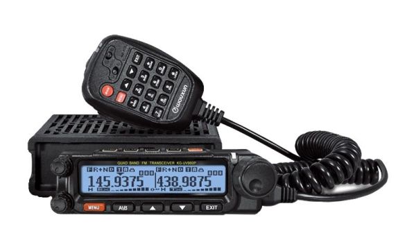
I recently decided to look into a 2m/70cm FM radio for the shack for use on the local 2m/70cm repeaters and was considering the offerings from Yaesu and Icom however, the Wouxun KG UV-980PL caught my eye as it is a quad band, full duplex radio. Not knowing much about Wouxun radios I had to do some research to get an idea of what it’s like. Generally the radio gets very good reviews and most mention the excellent build quality.

There are two versions of the 980P radio, the 980PL that offers 6/4/2m and 70cm bands and the 980P that offers 10/6/2m and 70cm. The 4m is a band I’ve been wanting to try for some time and the 980PL with it’s 4m band coverage became even more appealing.

Wouxun KG UV-980PL Quad Band FM Duplex Transceiver

I decided to take a trip down to Martin Lynch and Sons (MLANDS), a good 2 hours or more drive for me, so that I could get hands on with the radios that I had been looking at.

I invited Alan, G1SQB along for the ride and a day out playing with radios as he lives 3 miles away and we often chat on air.

Arriving at the store we grabbed a hot brew and set about playing with the great selection of radios on display.

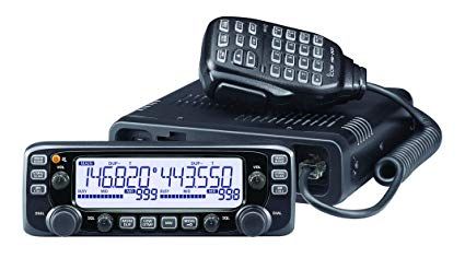
I initially looked at the Icom IC-2730E, a dual band full duplex transceiver that has been around for about 10 years and has good reviews. As expected the build quality is excellent and very easy to use. I found I was soon able to set up memories etc via the front panel controls. The only draw back is that it isn’t supported by the CHIRP programming software that I use. Other than that it certainly meets all the requirements for a 2m/70cm FM transceiver

Icom Ic-2730E Duplex FM Transceiver
Icom IC-2730E FM Duplex Transceiver

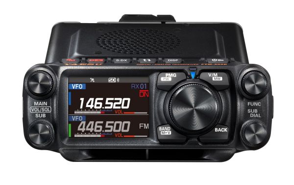
Next I moved on to the offerings from Yaesu including the FTM-500DE 2m/70cm transceiver. The colour screen is very nice and the menu system very easy to use however, the price is getting on for close to double that of the other radios and it doesn’t really offer anything more that interests me since I’m only looking for an analog radio.

Yaesu FTM-500DR dual band FM Transceiver

Sadly there wasn’t a Wouxun UV-980PL out on display and so I had to persuade the salesman to get one out of stock for me to play with. Unpacking the radio I was surprised at how good the build quality is, it really is comparable to the other radios that I had been looking at.

The Wouxun menu system is fairly easy to use once you’ve looked at the manual and got to grips the abbreviations used. The big plus is that this radio is CHIRP compatible with an optional programming cable (£19) and so loading the memories with repeaters etc will be extremely easy.

The Wouxun has dual receivers built in with a quad-plexer so, you can transmit on one band whilst listening to another band on the other receiver. One thing to note is that the 1st receiver covers all the bands, 6/4/2m and 70cm however, the 2nd receiver only covers 2m and 70cm so, it’s not possible to receive 4m and 6m at the same time. The radio also only has one antenna connection on the rear, would had been great if it had one connector for each receiver.

The really good thing about the Wouxun UV-980PL is that it comes with everything you will need, apart from the programming cable!

After much tinkering I decided to purchase the Wouxun KG UV-980PL, a Diamond V2000 6/2m and 70cm antenna plus 20m of Hyperflex-13 coax cable and connectors.

In the box you’ll find two mounting options for the removable head. There is a short connecting cable for use when the head is mounted directly on the radio body and a 5m long connecting cable for mounting the head remotely. This is really useful as I wanted to mount the head on a mic boom arm so that it’s easily accessible and didn’t clutter the desk space in the shack.

M0AWS Shack
Wouxun KG UV-980PL head mounted on a Mic boom arm

Since the radio also comes with the mobile mount I’ve fixed the radio body on the wall behind the PC monitor out the way. This setup has proven to be extremely good as I can see what’s happening on the display at a glance and easily grab the mic if called.

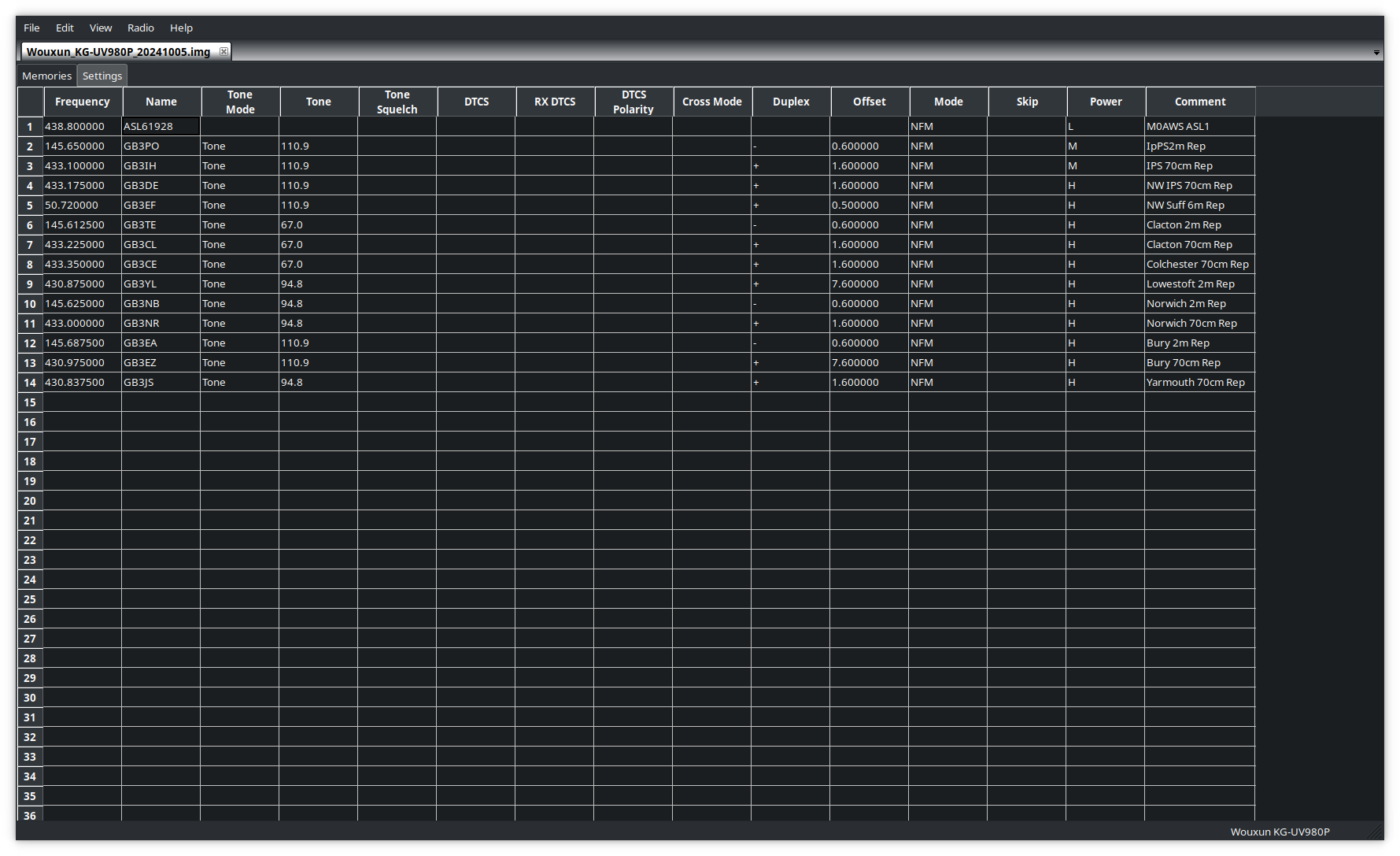
Programming the radio memories is extremely quick and easy using CHIRP. I had the local repeaters and my AllStarLink node frequencies and offsets uploaded to the radio in no time at all and was soon on air.

Programming the memories on the Wouxun UV-980PL using CHIRP

The microphone that comes with the radio is extremely good. You can operate most of the controls on the radio directly from the mic with ease and it has a good feel in the hand. Audio reports have also been very good and there’s no need to change it.

I’ve not yet got the new Diamond V2000 antenna erected but, I’ve been using the radio with my homebrew 2m/70cm end fed vertical dipole and my 4m band end fed vertical dipole and am getting excellent results. I can access all the local repeaters using the lowest power output setting and only have to use the medium/high setting for the repeaters that are further afield.

On the 4m band the radio performs well and I’ve been surprised at the distances I’ve been able to cover even though my 4m antenna is only 6-7m above the ground currently.

A few days after I got the new Wouxun radio there was an ARISS event whereby a group of Girl Guides would be talking to Astronaut Sunita Williams aboard the ISS. This was a great opportunity to test the receive capability of the radio and so I setup ready for the pass. Using just my simple 2m/70cm end fed vertical dipole I got great reception as can be heard in the video below.

Overall I’m extremely pleased with the Wouxun KG UV-980PL quad band radio and considering it’s much cheaper than the offerings from the main radio manufacturers it’s well built and performs extremely well. If you’re looking for a simple, analog FM radio for 6/4/2m/70cms then you can’t beat it!

More soon …
QO-100 Satellite Ground Station Complete Build

I get quite a few emails from readers of my blog asking how my QO-100 satellite station is put together and so, I thought perhaps now is a good time to put together an article detailing the complete build.

My QO-100 satellite ground station is built around my little Icom IC-705 QRP transceiver, it’s a great little rig and is ideal for the purpose of driving a 2.4Ghz transverter/up-converter.

Of course all the software used for the project is Opensource and freely available on the internet.

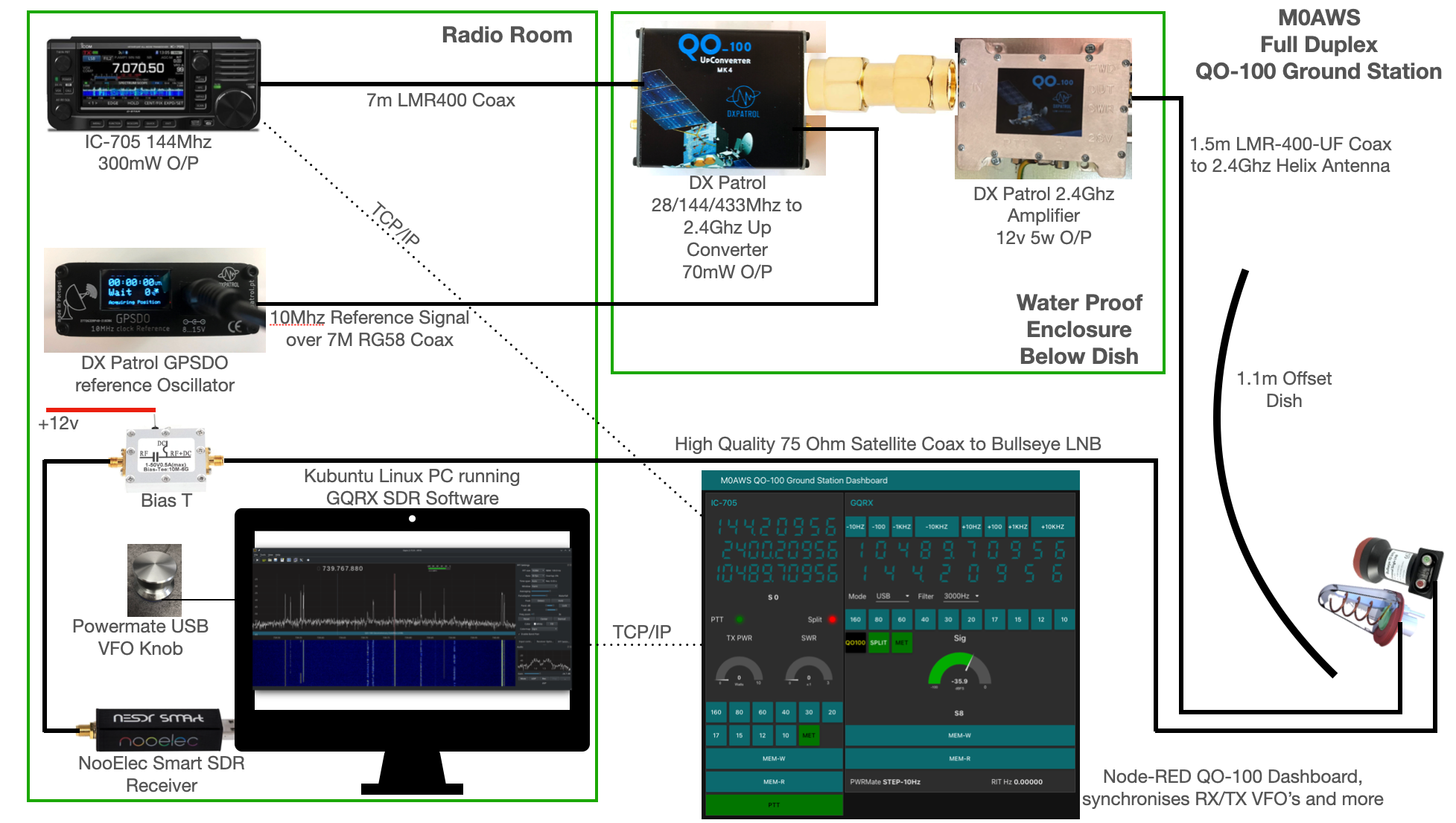
M0AWS QO-100 Ground Station Build Visual
M0AWS QO-100 Ground Station Build Visual (Click to Enlarge)

The station comprises of the following building blocks:

  • Icom IC-705 Transceiver
  • DXPatrol 28/144/433Mhz to 2.4Ghz Up-Converter
  • DXPatrol GPSDO Reference Oscillator
  • DXPatrol 2.4Ghz 5/12w Amplifier
  • Nolle Engineering 2.2 turn 2.4Ghz IceCone Helix Antenna
  • 1.1m (110cm) Off-set Dish
  • Bullseye 10Ghz LNB
  • Bias-T to feed 12v to LNB
  • NooElec SmartSDR Receiver
  • PC Running Kubuntu Linux Operating System
  • GQRX SDR Opensource Software
  • Griffin Powermate USB VFO Knob
  • QO-100 Ground Station Dashboard developed using Node-RED
  • LMR400-UF/RG58 Coax Cable
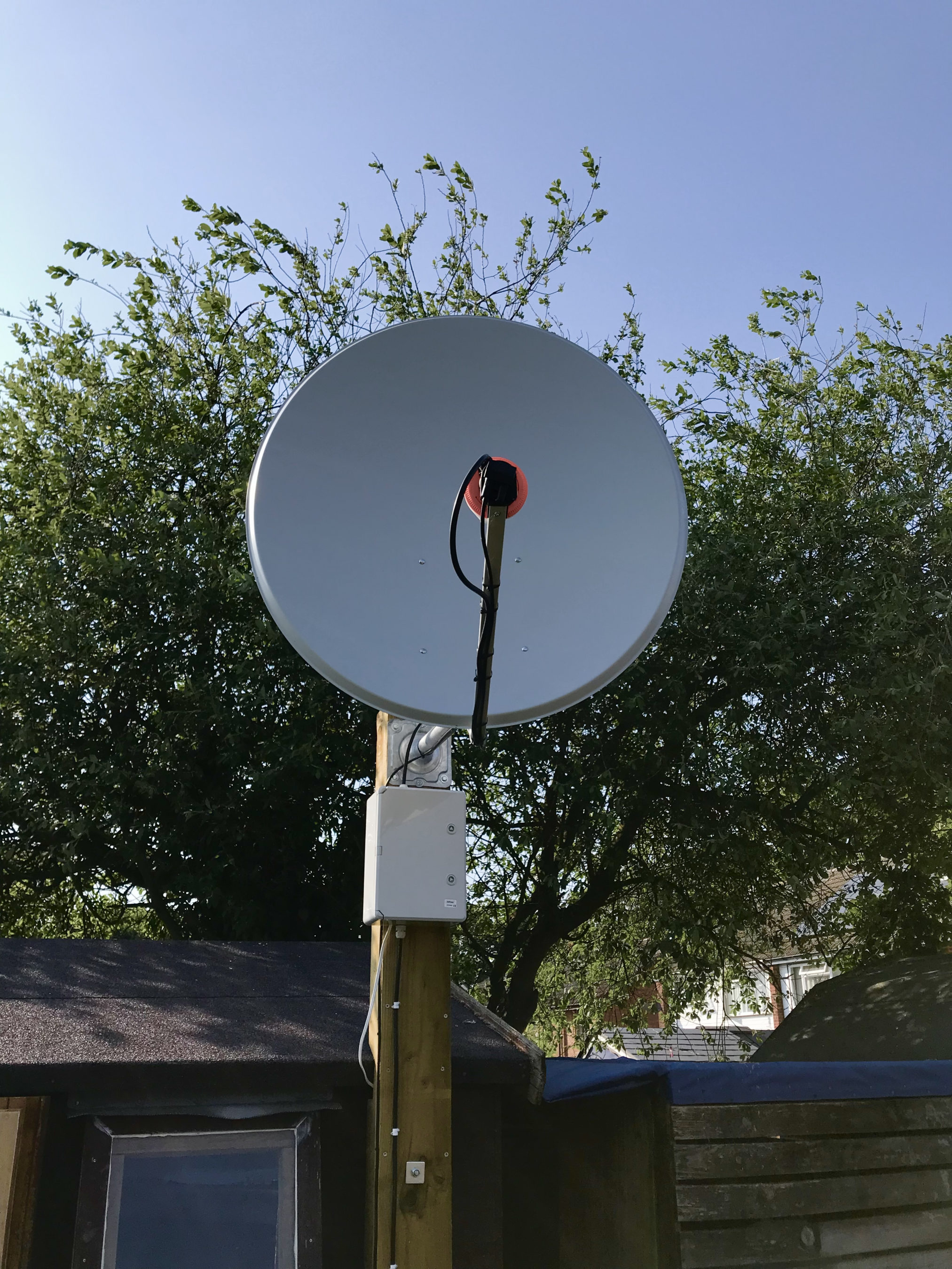
M0AWS QO-100 1.1m off-set Dish and IceCone Helix antenna ground station
M0AWS QO-100 1.1m (110cm) off-set Dish with IceCone Helix antenna and Bullseye LNB.

To get a good clear view of the QO-100 satellite I have the dish mount 3.2m above the ground. This keeps it well clear of anyone walking past in the garden and beams the signal up at an angle of 26.2 degrees keeping well clear of neighbouring gardens.

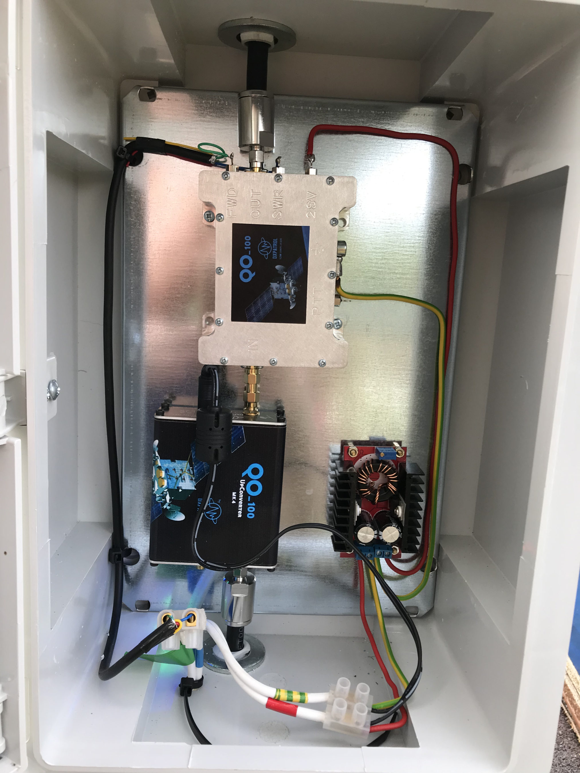
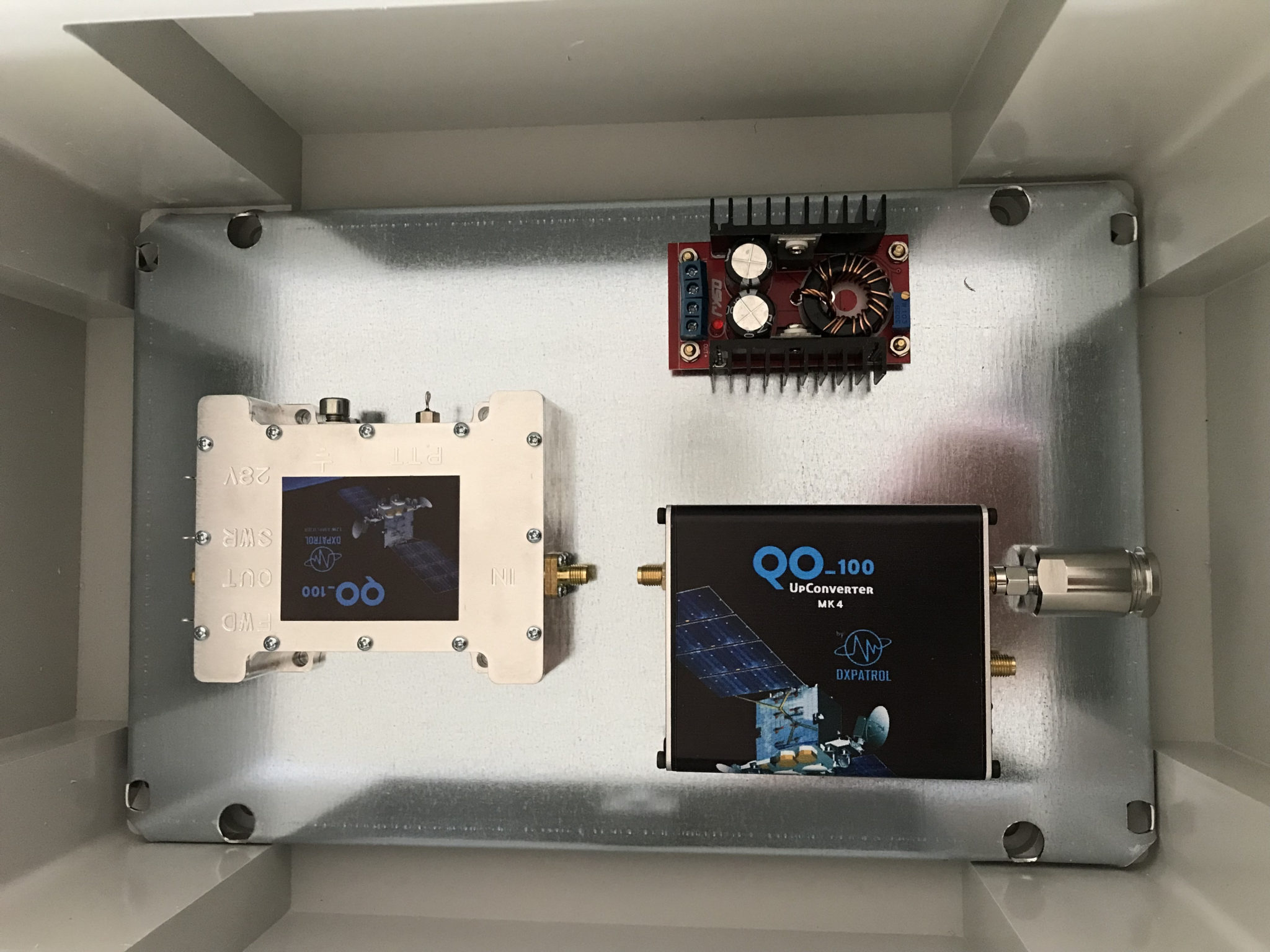
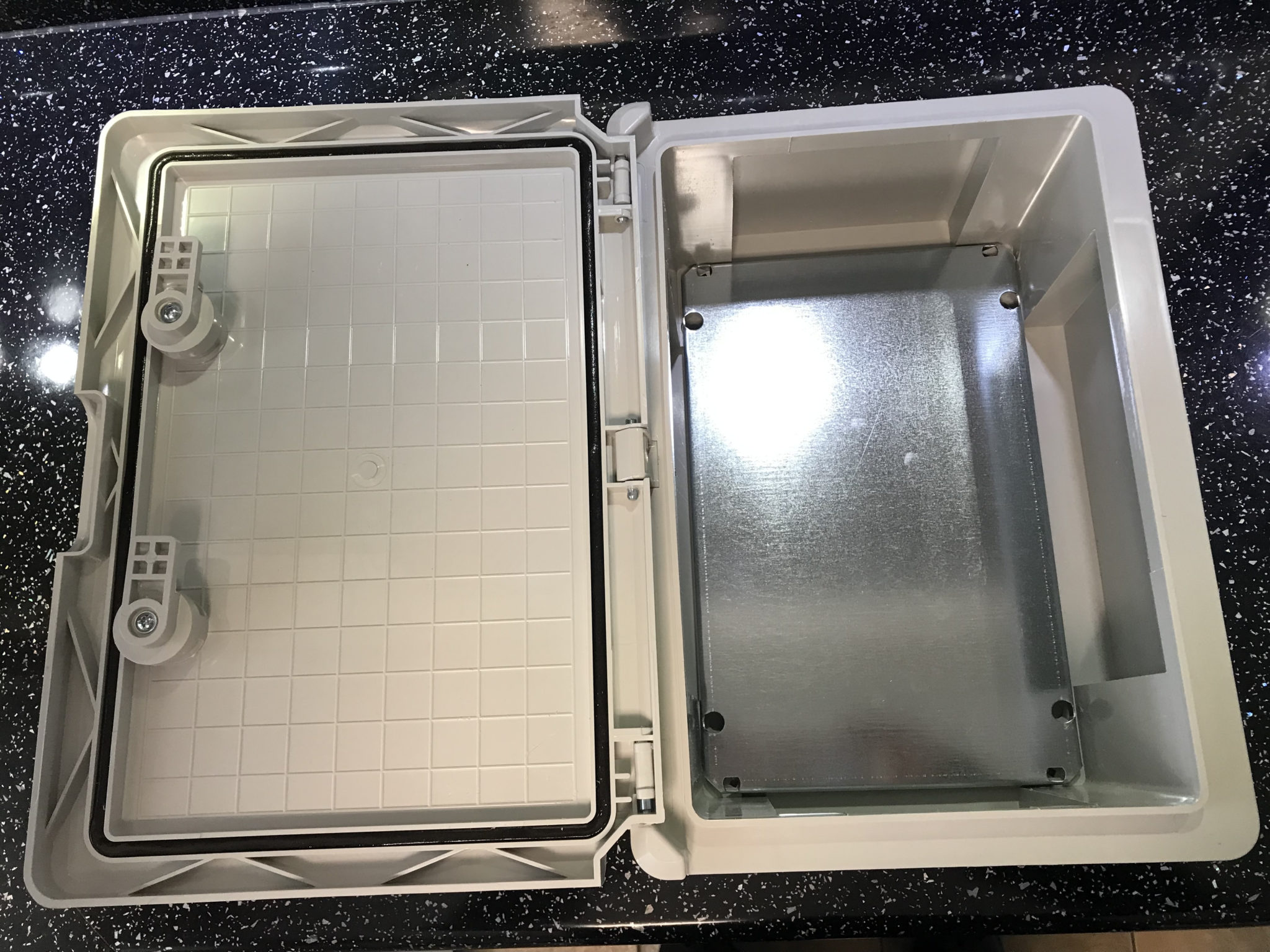
The waterproof enclosure below the dish houses all the 2.4Ghz equipment so that the distance between the feed point and the amplifier are kept to a minimum.

The DXPatrol amplifier is spec’d to run at 28v/12w or 12v/5w, I found that running it at 28v produced too much output for the satellite and would cause the LEILA alarm on the satellite to trip constantly. Running the amp at 12v with a maximum of 5w output (average 2.5-3.5w) is more than enough for me to have a 5/9+10 signal on the transponder.

The large 1.1m dish gives me quite an advantage on receive enabling me to hear the very weak stations with ease compared to other stations.

2.4Ghz ground station enclosure ready for testing

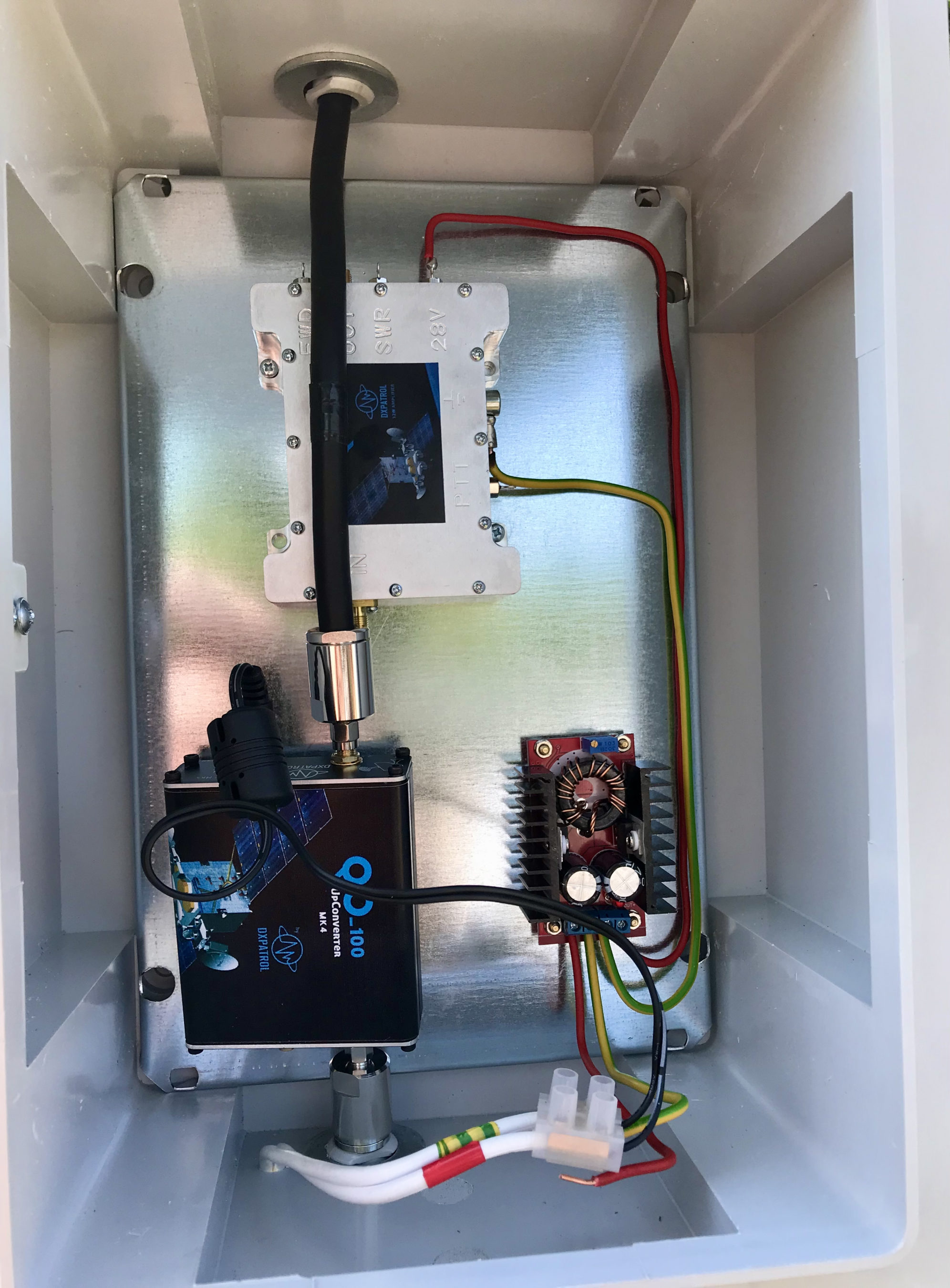
The photo above shows the 2.4Ghz equipment mounted in the waterproof enclosure below the dish. This photo was taken during the initial build phase before I rewired it so, the amplifier is shown connected to the 28v feed. To rewire the amp to 12v was just a matter of removing the 28v converter and connecting the amp directly to the 12v feed instead. This reduced the output from a maximum of 12w down to a maximum of 5w giving a much better (considerate) level on the satellite.

It’s important to keep all interconnects as short as possible as at 2.4Ghz it is very easy to build up a lot of loss between devices.

For the connection from the IC-705 to the 2.4Ghz Up-Converter I used a 7m run of
LMR-400 coax cable. The IC-705 is set to put out just 300mW on 144Mhz up to the 2.4Ghz converter and so it’s important to use a good quality coax cable.

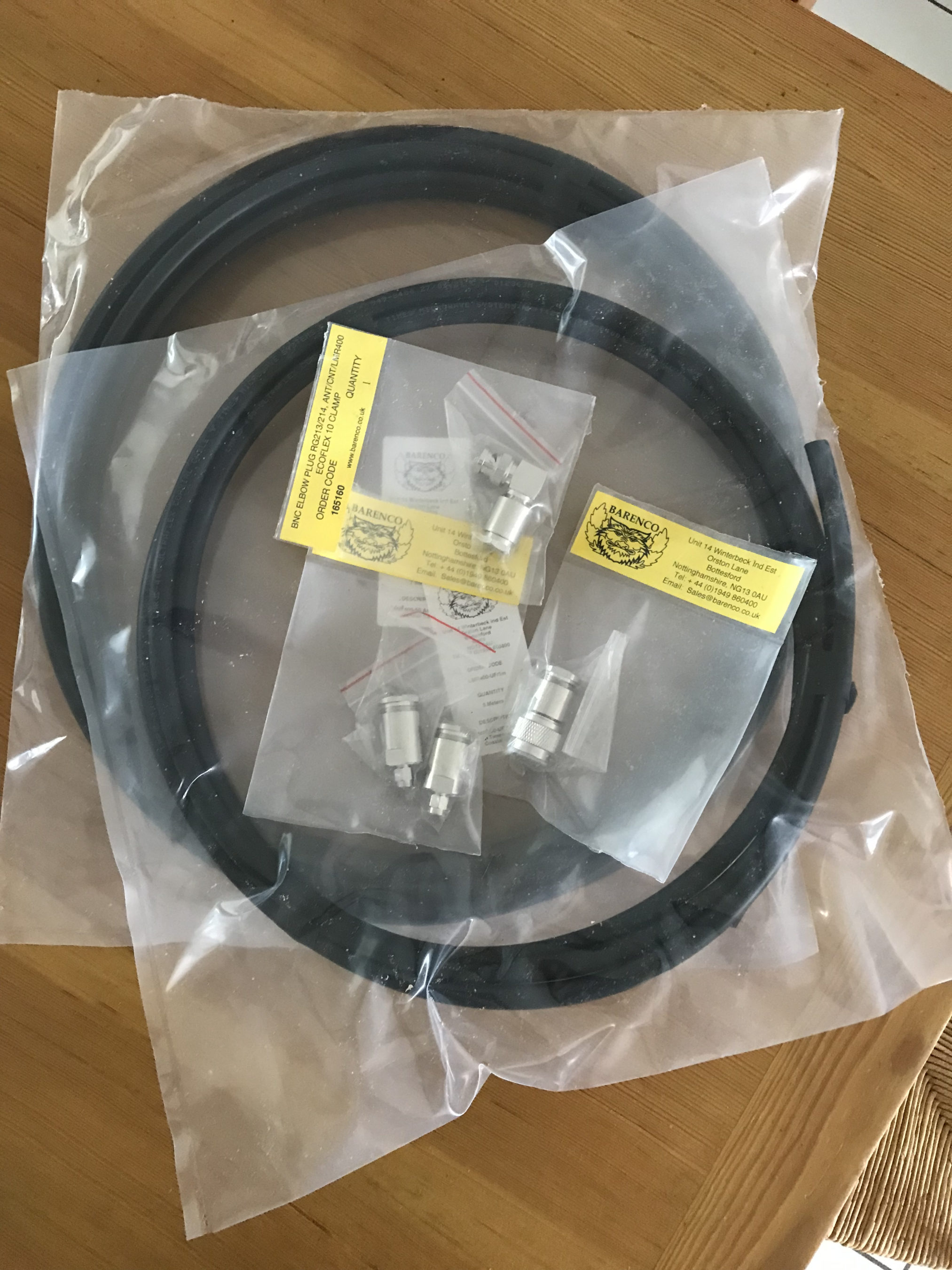
Once again the output from the 2.4Ghz amplifier uses 1.5m of LMR-400-UF coax cable to feed up to the 2.2 turn Icecone Helix Antenna mounted on the dish. This keeps loss to a minimum and is well worth the investment.

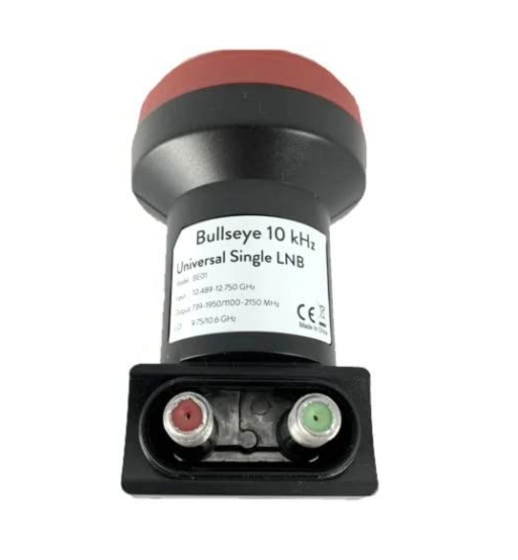
Bullseye 10Khz High Stability Unversal Single LNB for 10.489-12.750Ghz

The receive path starts with a Bullseye LNB, this is a high gain LNB that is probably one of the best you could use for QO-100 operations. It’s fairly stable frequency wise but, does drift a little in the summer months with the high temperature changes but, overall it really is a very good LNB.

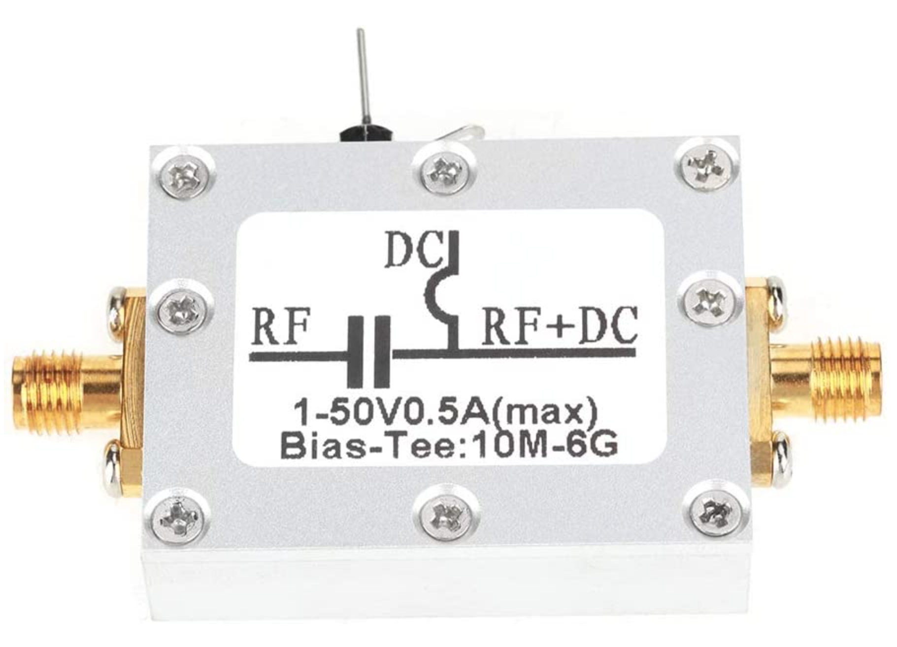
The 12v feed to the LNB is via the coax and is injected by the Bias-T device that is in the radio shack. This 12v feed powers the LNA and associated electronics in the LNB to provide a gain of 50-60dB.

Bias-T to inject 12v feed into the coax for the Bullseye LNB

From the Bias-T the coax comes down to the NooElec SmartSDR receiver. This is a really cheap SDR device (<£35 on Amazon) based on the RTL-SDR device but, it works incredibly well. I originally used a Funcube Dongle Pro+ for the receive side however, it really didn’t handle large signals very well and there was a lot of signal ghosting so, I swapped it out for the NooElec SDR and haven’t looked back since.

The NooElec SmartSDR is controlled via the excellent Opensource software GQRX SDR. I’ve been using GQRX SDR for some years now and it’s proven itself to be extremely stable and reliable with support for a good number of SDR devices.

To enhance the operation of the SDR device I have added a Griffin Powermate VFO knob to the build. This is an old USB device that I originally purchased to control my Flex3000 transceiver but, since I sold that many moons ago I decided to use it as a VFO knob in my QO-100 ground station. Details on how I got it working with the station are detailed in this blog article.

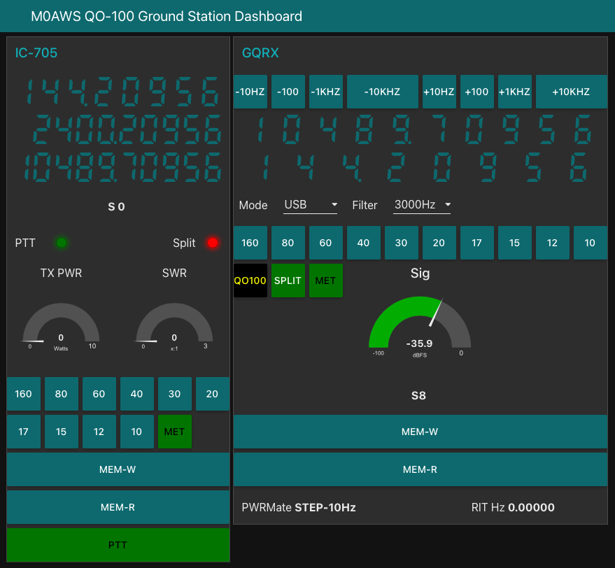
Having the need for full duplex operation on the satellite this complicates things when it comes to VFO tracking and general control of the two radios involved in the solution and so I set about creating a QO-100 Dashboard using the great Node-RED graphical programming environment to create a web app that simplifies the management of the entire setup.

M0AWS QO-100 ground Station Control Dashboard built using Node-RED.

The QO-100 Dashboard synchronises the transmit and receive VFO’s, enables split operation so that you can transmit and receive on different frequencies at the same time and a whole host of other things using very little code. Most of the functionality is created using standard Node-RED nodes. More info on Node-RED can be found on the Opensource.radio Wiki or from the menu’s above.

I’ll be publishing an article all about the QO-100 Dashboard in the very near future along with a downloadable flow file.

I’m extremely pleased with how well the ground station works and have had well in excess of 500 QSO’s on the QO-100 satellite over the last last year.

More soon …
Home-Brew 12v DC Distribution Box

I’ve been wanting to tidy up the cabling to the 12v DC PSU for some time in the radio shack as like many HAMs I have a number of radios/devices that all need a 12v feed but, only two connectors on the front of the PSU. The net result was a birds nest of wires all connected to the PSU making it impossible to disconnect one device without others getting disconnected at the same time.

Looking online I found that many of the HAM outlets stores sell nice little 12v DC distribution boxes that would be ideal however, they’re all priced somewhat high for what they are so, I decided to purchase the parts and make one myself.

Searching on Amazon I found all the necessary parts for less than a quarter of the cost of commercially made units. A couple of days later the parts arrived and sat on my desk in the shack for a few weeks. Yesterday I finally found the time to make a start on the project.

M0AWS home-brew 12v DC Distribution Box

After much drilling and filing I had the necessary holes/slots cut in the plastic box for the 4mm connectors and fuse holders and started wiring them up. Part way through my 30 year old soldering iron decided to die and so I had to stop and wait for a replacement to arrive.

M0AWS completed 12v DC Distribution Box

With the new soldering iron in hand it only took 30mins or so to complete all the joints and I soon had the box together ready to test with my multimeter to ensure I didn’t have any shorts or crossed wires.

With testing complete and fuses in place I connected it up to the PSU and then connected all the devices one by one checking for voltage drops as I went.

M0AWS 12v DC Distribution Box

I now have my CG3000 remote auto ATU, GPSDO, QO-100 ground station and IC-705 all nicely connected in a much tidier fashion than before, all for considerably less than the commercially available alternatives.

More soon …
Just one little rain drop is all it takes!

We’ve not had rain for over 6 weeks here in Eyke, Suffolk. The ground is incredibly dry and dusty. The farmers have been pulling vast quantities of water from their bore holes for weeks to keep the crops alive and we’ve been putting extra water out for the birds and animals that visit our garden daily.

Then one night we had about 30mins of light rain, not much at all and it was consumed by the dry earth is seconds. By morning you’d never of known it had rained however, strangely the next day when I fired up my QO-100 ground station I noticed that my signal into the satellite was way down from it’s normal S9+10dB level. Checking drive into the up-converter and SWR at the IC-705 everything looked fine. I then decided to check the SWR from the 2.4Ghz amplifier output only to find that it was off the scale.

I checked inside the enclosure for water ingress but, all was bone dry as normal. I disconnected the coax cable from the output of the amplifier and the IceCone Helix uplink antenna, tested with a multimeter and found everything was fine, no short and perfect continuity.

After scratching my head for a few minutes I decided to take both the N Type and SMA connectors apart to look for water ingress. Since the inside of the enclosure was dry I wasn’t expecting to find anything.

The N connector at the Helix antenna end on the dish LNB mount was perfectly dry, no water ingress at all. The layers of self amalgamating tape I’d put over the connector had done its job perfectly. Shame I had cut the tape off to remove the plug!

Upon removing the SMA connector at the amplifier end of the coax I noticed a tiny drop of water in the bottom of the housing where the pin goes through the white plastic insulator, not a good sign.

Sure enough upon further inspection I found that the white plastic disc that is situated above the pin on the centre conductor was wet and the coax braid felt damp. I knew immediately this wasn’t good.

At first I didn’t understand how there could possibly be water in the SMA connector when the rest of the enclosure was dry. Where the coax goes into the top of the enclosure there is a water tight junction that tightly grips the coax cable and seals it, supposedly stopping water ingress.

Since there was water in the SMA connector I feared that perhaps the water had gone further and entered into the amplifier so, I decided to remove the amp from the enclosure and remove the top cover to check.

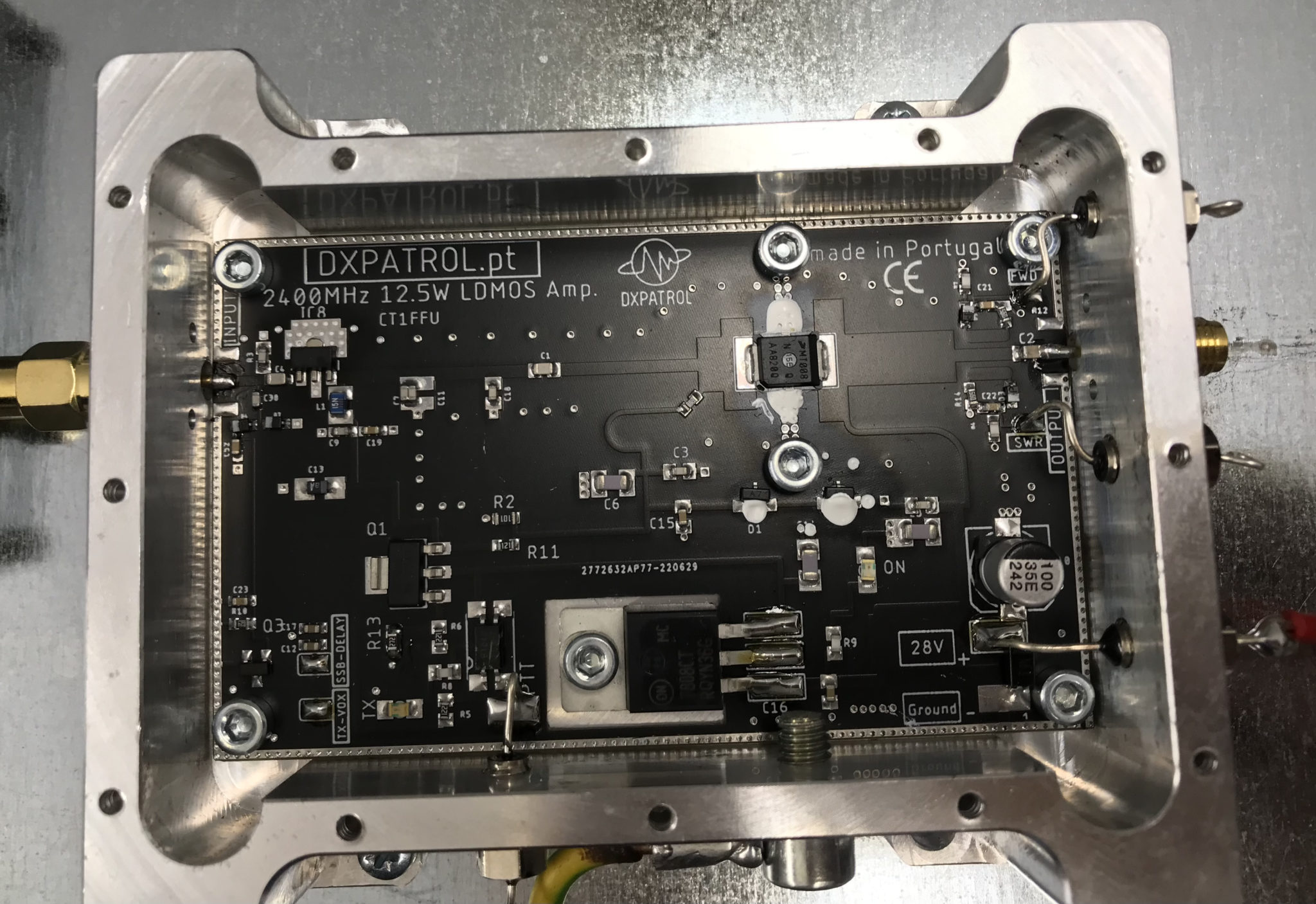
2.4Ghz amplifier with top cover removed

After some close inspection I found the amp to be perfectly dry and free from water ingress, a relief for sure.

Before putting it all back together I decided solder on a pair of wires to the SWR and FWD-PWR pins on the amplifier and run them down into the radio room. This would then allow me to check the SWR and power output without having to get up to the enclosure with a multimeter.

Once this was done I then set about cutting 5cm of LMR-400-UF off at the SMA connector end so that I had a fully dry piece of coax cable to refit the SMA connector to. Having to do this outside and up a ladder wasn’t the easiest but, with a little perseverance and cooperation from the breeze I managed to get the pin soldered back onto the end of the coax and the connector back together.

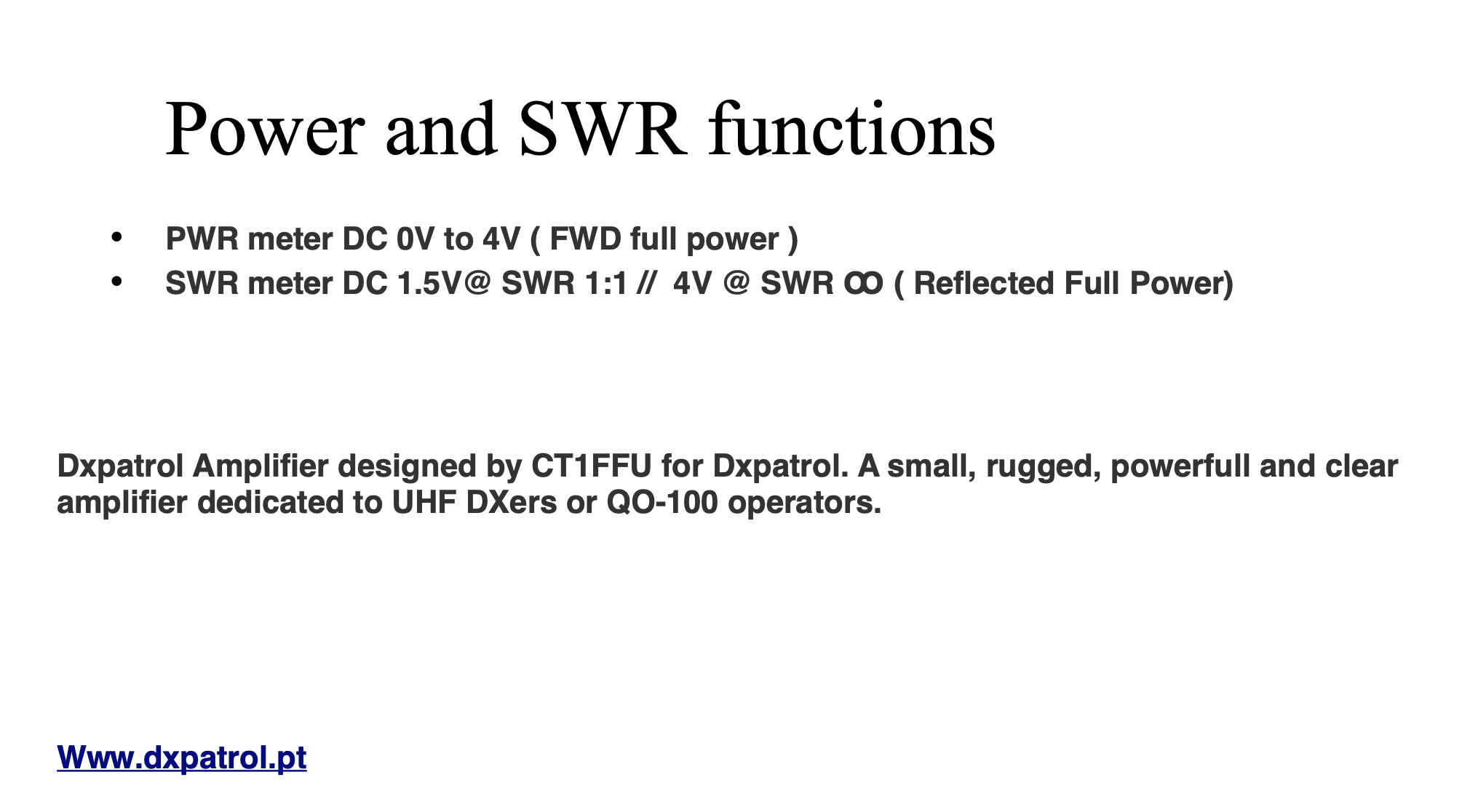
I reconnected the amp to the 28v feed so that I could check the SWR and power output at full rating instead of the lower 12v setting that I had been using. Checking the voltage on the SWR pin I found that it fluctuated between 0.2v and 0.44v. This wasn’t what I was expecting as the PDF manual for the amplifier states that with a 1:1 SWR you should see 1.5v on the SWR pin.

DXPatrol 2.4Ghz Amplifier Manual Page for SWR/FWD-PWR voltages

After checking all the connections and retesting and getting the same voltage reading I emailed Antonio at DXPatrol detailing my findings and asking if he could advise on the voltages I was seeing. Sure enough in no time at all he came back to me saying that the manual was incorrect and that I should see between 0.2 and 0.5v on the SWR pin for a good SWR match. Being happy that the readings I was getting were fine I emailed back thanking him for his swift reply and then moved on to check the power output safely in the knowledge that the SWR reading was within tolerances.

Checking the FWD-PWR pin I found that on SSB the voltage was fluctuating between 2v and 3v, this equates to 6w and 9w output, about right for SSB. Switching to CW mode I found the full 4v was present on the FWD-PWR pin confirming I had the full 12w output from the amp. Of course this set off “Leila” on the satellite immediately as I was a huge signal on the bird with such high power output and was a reminder to reconnect the amp to the 12v supply instead to ensure I didn’t exceed 5w output and thus keeping to a considerate level on the transponder input.

After further investigation I came to the conclusion that the water ingress could only of come from the cable inlet on the top of the enclosure, it had then run down the coax cable into the SMA connector. Somewhat annoying as the inlet is supposed to be a water tight fixing. Once I had everything back in the enclosure and securely fitted, I covered the cable inlet and coax in self amalgamating tape in the hope that this would stop any further water ingress. I also re-taped the N connector at the antenna end as well to ensure it was also protected from water ingress in the future.

2.4Ghz ground station enclosure ready for testing

I’m hoping this will be the end of my water ingress issues and that I have a dry 2.4ghz future ahead of me.

More soon …
My First QO-100 Satellite QSO

I’ve been waiting for over a week so far for a male to male SMA connector to arrive from Amazon so that I can connect the 2.4Ghz up-converter to the 2.4Ghz amplifier. Since it still hasn’t arrived I decided to connect the up-converter directly to the IceCone Helix antenna to see if I could get a signal into the QO-100 satellite.

To my surprise I could easily hear my CW signal on QO-100 even though the total output from the up-converter is only 200mW.

I didn’t expect to be able to hear my signal since it’s a tiny amount of power that has to travel some 22500 miles to the satellite but, I could hear it and was amazed that it was peaking S8 on my SDR receiver.

2.4Ghz Up-COnverter connected directly to the antenna bypassing the 2.4Ghz Amplifier
2.4Ghz Up-Converter connected directly to the antenna bypassing the 2.4Ghz Amplifier

Being excited I put out a CQ call that was soon answered by OH5LK, Jussi in Finland. Jussi gave me a 579 report which I was extremely pleased with. He was of course much stronger at a 599+ at my end. We had a quick QSO and exchanged details without any problems at all. Its really nice to get a QRPp contact without any QSB or QRM.

M0AWS QO-100 1.1m off-set Dish and IceCone Helix antenna ground station

Neil, G7UFO who I chat with regularly in the Matrix Amateur Radio Satellites room has posted a connector out to me so I’m hoping it will arrive on Monday and then I’ll be able to connect the amplifier and hopefully get a few SSB contacts.

UPDATE: I’ve since had 2 SSB contacts via QO-100 using just the 200mW O/P from the up-converter. Both times I got a 3/3 report not brilliant but, perfectly acceptable for the amount of power I’m putting out.

More soon …
UPDATE: QO-100 Node Red Dashboard

I’ve been making a few improvements to my QO-100 Node Red Dashboard whilst waiting for the 2.4Ghz hardware to arrive. I’ve added the ability to split the RX and TX VFOs so that I can tune away from the TX frequency for working split stations or for tuning to slightly off frequency stations. I also added a series of tuning buttons to the top of the GQRX side of the dashboard to enable easy tuning using the trackball connected to my Kubuntu PC. This worked well but, I really missed having a real VFO knob like a conventional radio.

As I had a Griffin Powewrmate USB VFO from a previous SDR radio I added it to the flow as well so that I had a physical VFO knob for the SDR receiver. Details on how I got it working using evtest and a simple BASH script are in the Griffin Powermate article.

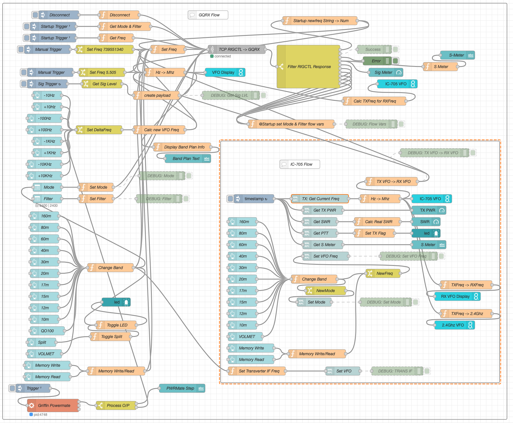
M0AWS QO-100 Node Red Dashboard Flow

The Node Red flow is looking a little busier with the addition of split mode and the Griffin Powermate USB VFO which has really enhanced the useability of the solution. It’s very impressive what can be achieved with Node Red with a little imagination. You really don’t need to be a heavy weight programmer to make things work.

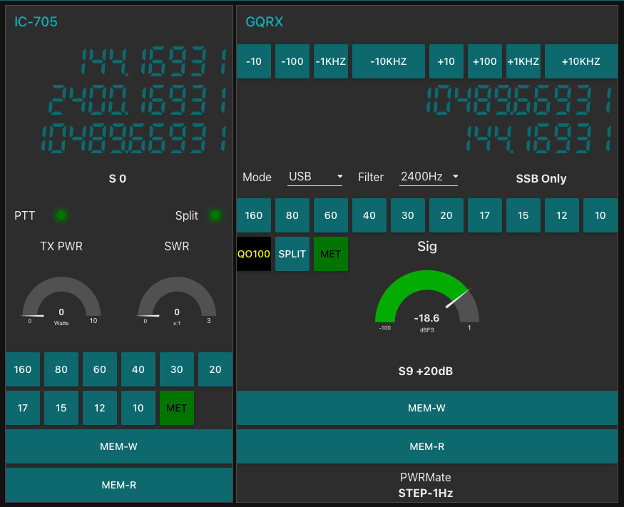
M0AWS QO-100 Node Red Dashboard as of 07/06/23

I also put together some code to calculate the S Meter reading from the dBFS data the GQRX SDR software generates. It’s not 100% accurate but, it’s close enough to be useful.

On the IC-705 side of the Dashboard I also now display the 2.4Ghz uplink frequency so that it’s available for logging.

So with the QO-100 Dashboard ready to go live I have now started putting together the 2.4Ghz transmit path of the ground station. I have the 2.4Ghz transverter and matching 12w amplifier from DXPatrol, the IceCone Helix 2.4Ghz antenna from Nolle Engineering, some LMR-400-UF and connectors from Barenco and an appropriate water proof enclosure from Screwfix to fit all the kit into however, I’m now being held up by one simple little SMA male to SMA male connector that I need to connect the transverter and amp together.

The SMA connector has been ordered but, is taking a month of Sundays to arrive! Hopefully it’ll arrive soon and I’ll finally get on the QO-100 satellite and start enjoying the fun.

More soon …
New radio shack almost complete

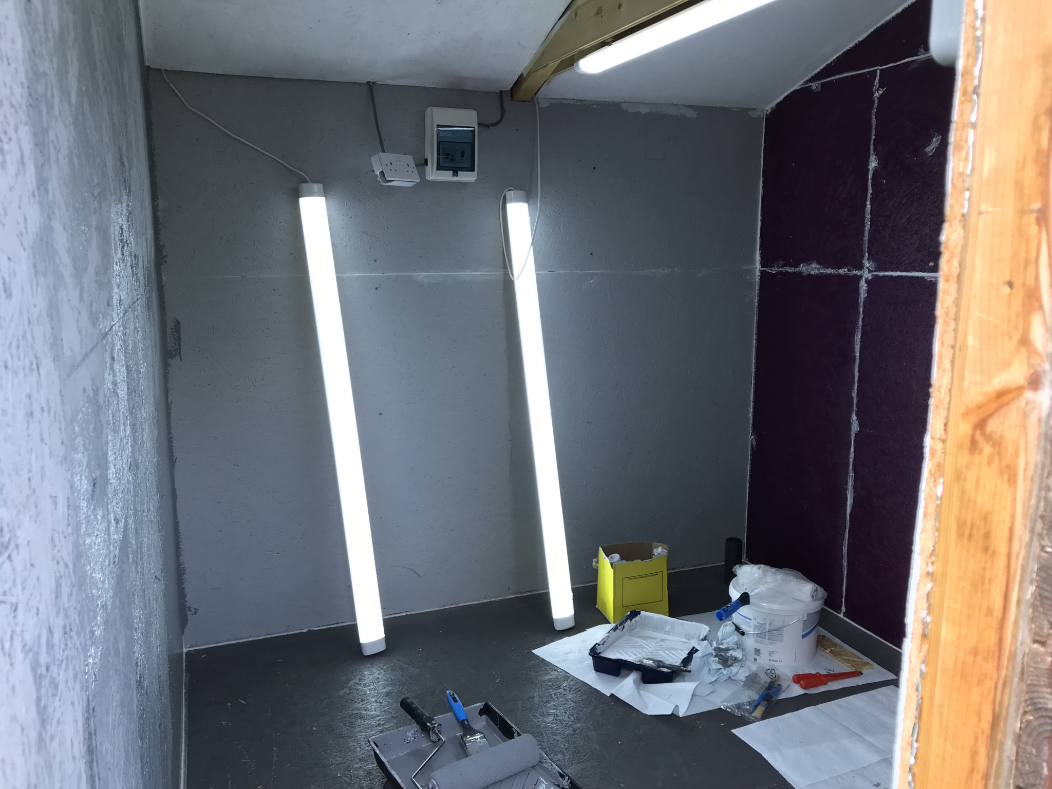
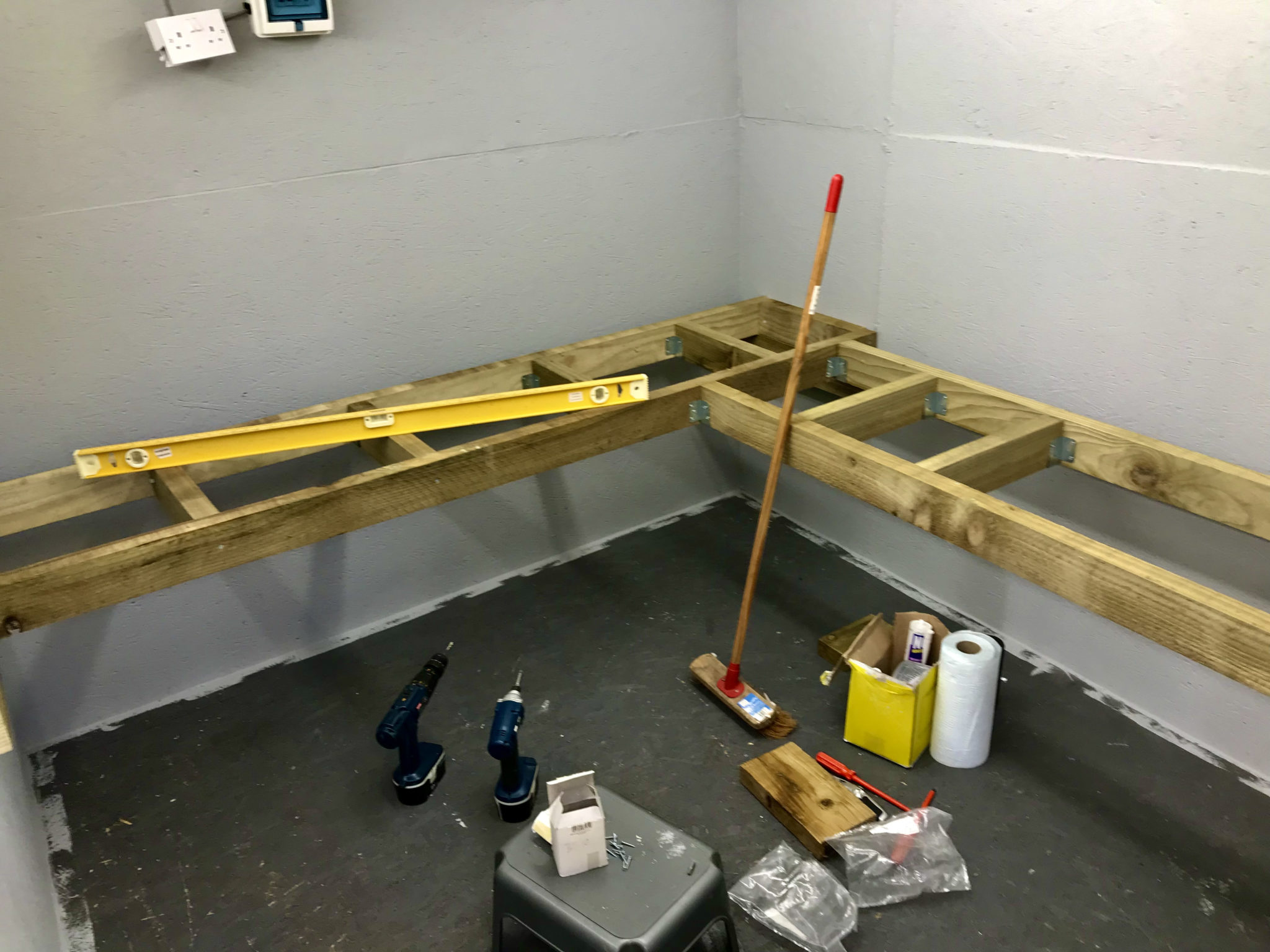
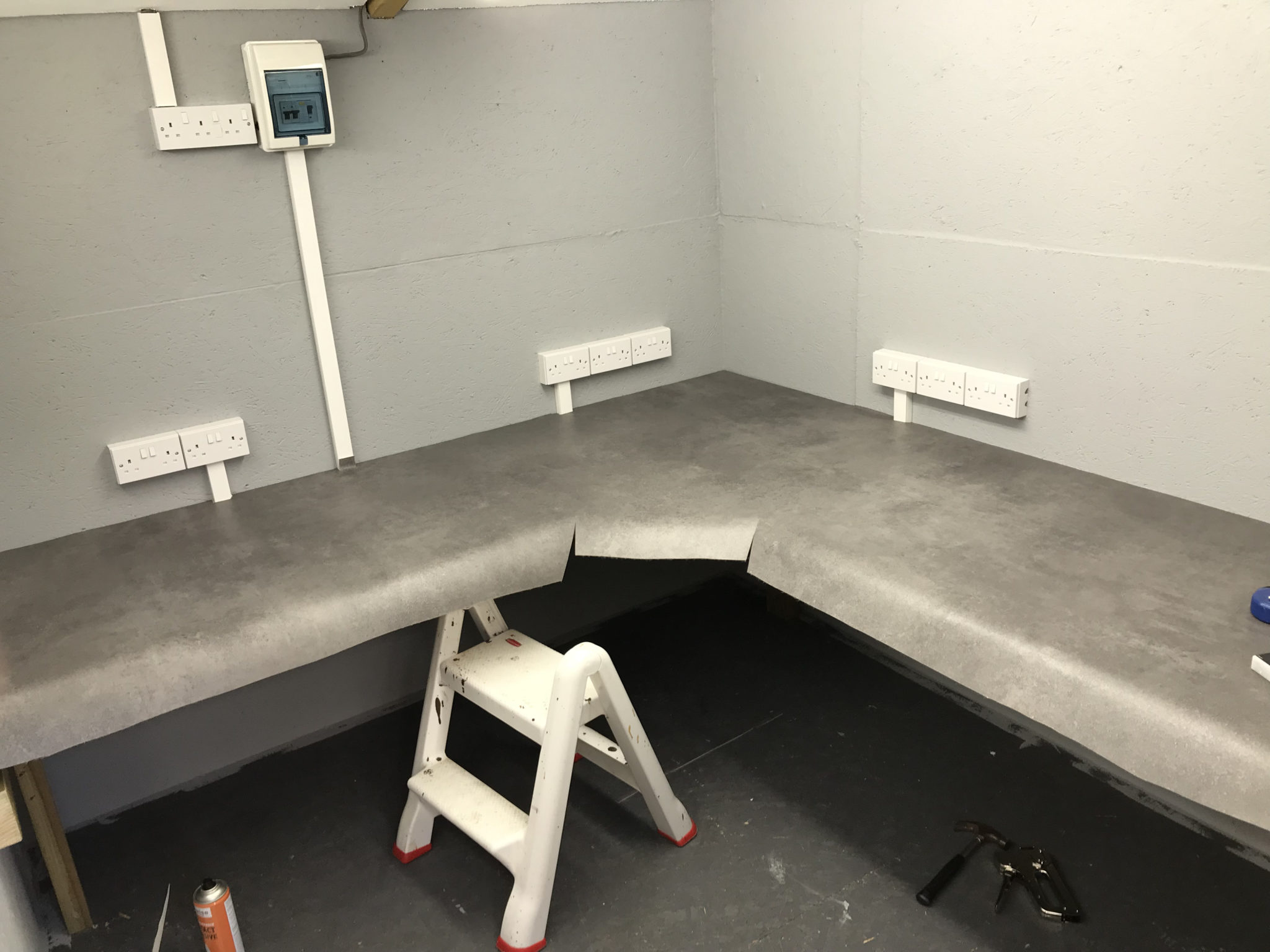
Over the last couple of weeks my wife and I have been busy converting part of my old motorcycle workshop into my new radio shack.

To save money we’ve custom built the desk ourselves using timber from a local supplier. I’ve done all the 240v power and lighting installation with a dedicated feed from the main distribution panel in the house.

Custom building the desk gives us a huge advantage in that it allows us to maximise usage of the available space. Using 10mm sterling board covered with 10mm plywood makes the desk solid enough to sit on whilst fitting all the power sockets.

Bennie overseeing the project

We used a good quality padded vinyl flooring for the desk covering as it allowed us to cover the desk area in one continuous piece. It was challenging to get all the cuts in the right place and get it glued down without it moving but, with a little care and patience we got it done. We’re both really pleased with the results!

I’ve just got to install some cable management and shelving to complete the project but, overall I’m really pleased with the new radio shack. I’m looking forward to the winter low band DXing season!

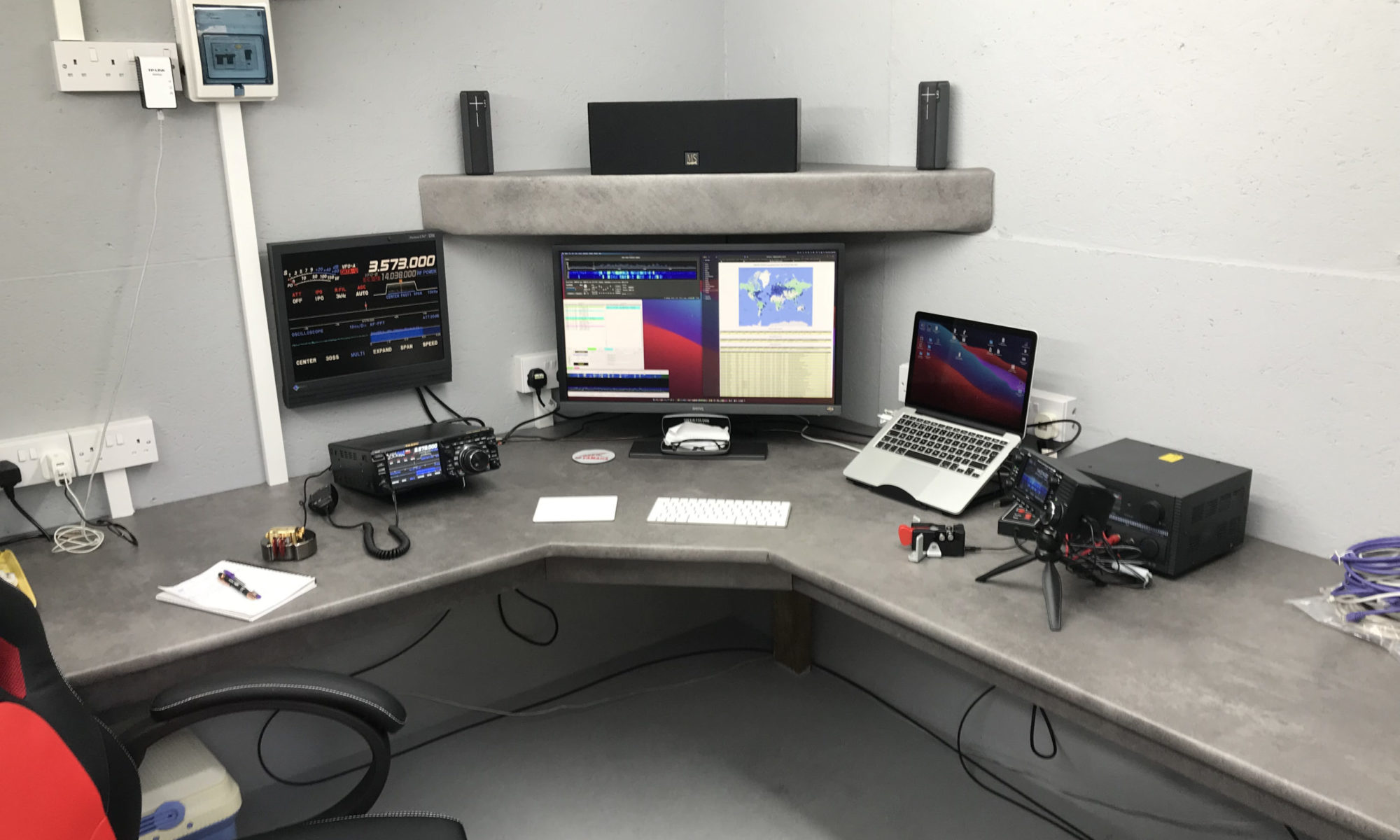
The new M0AWS Radio Shack

More soon …