The 5 things that have revolutionised my Radio Shack

The articles I write for the blog are mostly technical but, I thought it was about time that I wrote this article as it’s been buzzing around inside my head for some time now.

So, what are the 5 things that I have found revolutionary in my shack that have brought new, exciting ideas and projects to life making amateur radio more enjoyable.

1: A RaspberryPi Single Board Computer
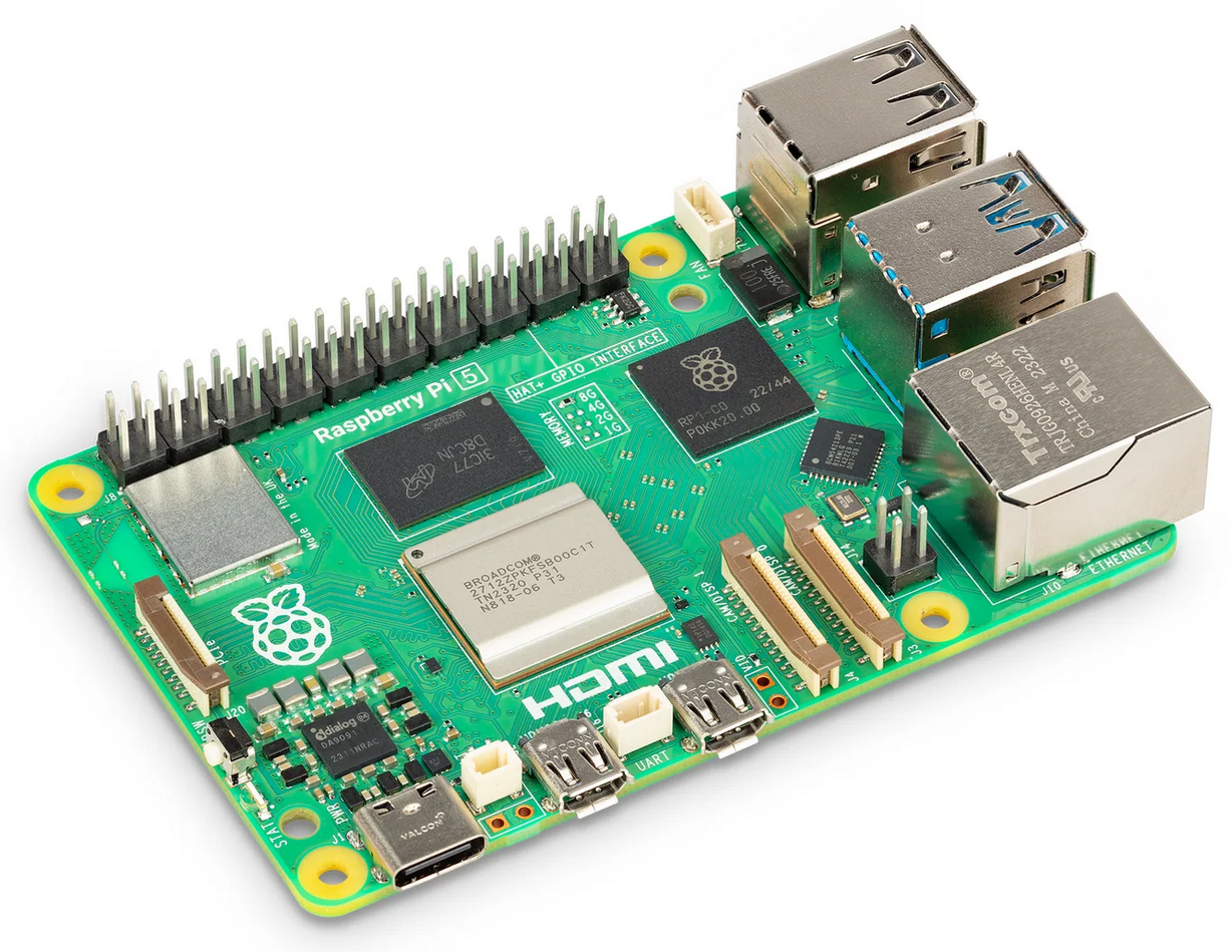
RaspberryPi 5 Single Board Computer

Ever since the first RaspberryPi Single Board Computer (SBC) was released I’ve been a huge fan. This little credit card sized number cruncher has been the base for so many projects, it has to be the first on my list.

The RaspberryPi SBC has been through a few iterations since its initial conception and is now powerful enough to take on most tasks that any radio HAM is going to throw at it.

So, what have I done with them?

Well I’ve used them to run Node-Red services for my many web app dashboards that control things like my QO-100 Satellite Ground Station, UPS power monitoring, Internet speed graphs, server and virtual machine monitoring, AllStarLink nodes, hosting websites, building an SDR shortwave receiver, running HAM Clock / Open HAM Clock, developing my own software, hosting virtual machines and a whole host of other fun and interesting things. I’m even writing this article using my RaspberryPi 500+ computer that is my daily desktop PC.

There are an endless number of things you can do with a RaspberryPi to bring new life and functionality to your radio hobby.

Want to get into Amateur TV?
Want to decode digital modes real time?
Want to track aircraft in the sky real time on a virtual radar screen?
Want to search the shortwave bands for stations of interest?
Want to host your own blog and website?

All these things and a lot more are easily within reach with a RaspberryPi.

The RaspberryPi is only limited by your imagination, the more imaginative you are the more your number crunching little friend will do.

2: A 3D Printer
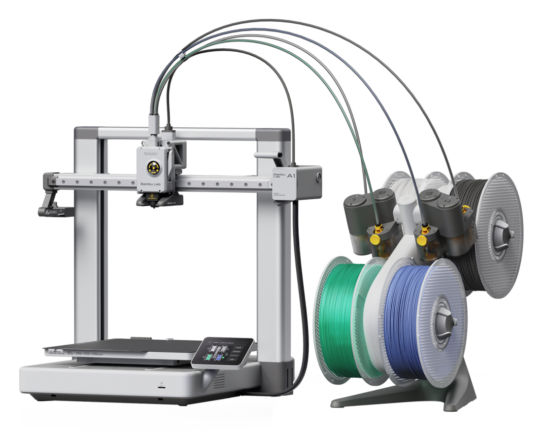
Bambu Lab A1 Combo 3D Printer

Every HAM should have a 3D printer. These manufacturing marvels bring a new level of quality, design and simplicity to your HAM radio projects. I’ve found it incredibly useful since venturing into the rabbit hole that is 3D printing. When I think back to the weeks and months of my life I’ve spent making cabinets and boxes out of sheet metal, aluminium or wood for the numerous projects I’ve built over the years, a 3D printer would had made my life so much easier. 3D printing has revolutionised the making of things for the Amateur Radio home brewer.

There’s a multitude of useful things on websites like Printables, Thingiverse , Makerworld and others where you can just download the files and print high quality designs for all those things you’ve wanted to do but, don’t have the time or inclination to craft by hand.

The real satisfaction with 3D printing comes from designing your own things and making them. My first project was to design and print a fan cooling system for my Xiegu XPA125B amplifier.

From the factory the amp is passively cooled and doesn’t take long for the heat-sink to become saturated resulting in a high operating temperature. I was never happy with this and so was determined to resolve the problem.

Getting to grips with TinkerCAD was a bit of a vertical learning curve but, after a few mistakes and design mishaps I soon had it under my belt and pressed on with designing the cooler unit.
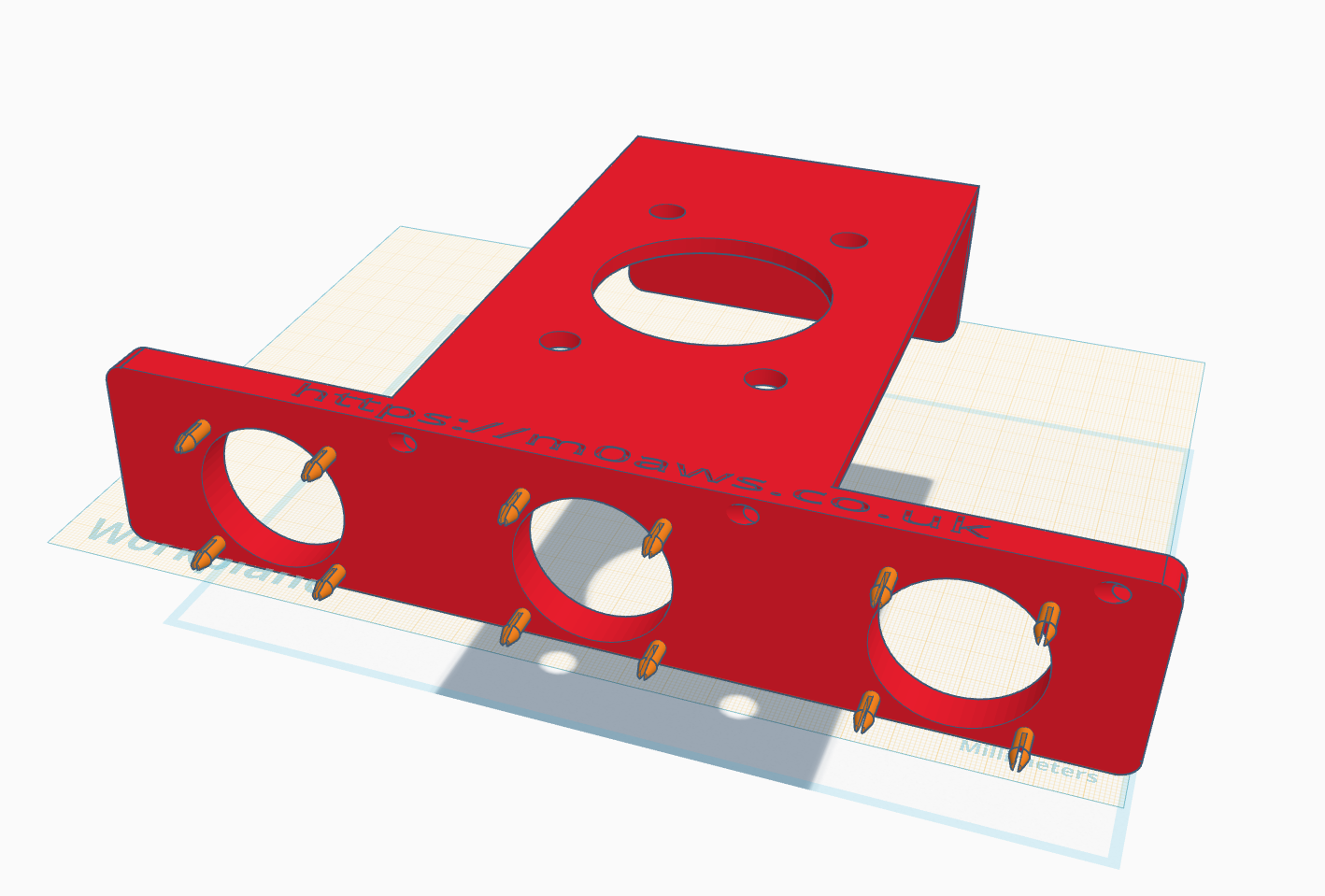
Designing the Xiegu XPA125b cooling system using tinkerCAD.

It’s not until you start designing and manufacturing things that you suddenly realise how much effort goes into them but, I persevered and over the period of about a week or so I had a perfectly fitting, operational cooling system that kept the amp super cool regardless of how long I waffled on for on the HF bands.

Once you’ve got your first design made you suddenly find yourself wanting to improve it and add things. In my case this was adding a Hermes Lite 2 holder to the top of the amp cooler and then a top shelf to hold my cross needle SWR and power meter.

Since then I’ve progressed massively with my designs and have even designed and printed things for other HAMs and family members, it’s totally addictive!

I can highly recommend the Bambu Lab A1 Combo (As shown above). It’s a quality piece of equipment that has operated faultlessly since purchase. Right now it’s printing a case for my RaspberryPi 4, just one of the many projects I’ve used it for since becoming a happy owner.
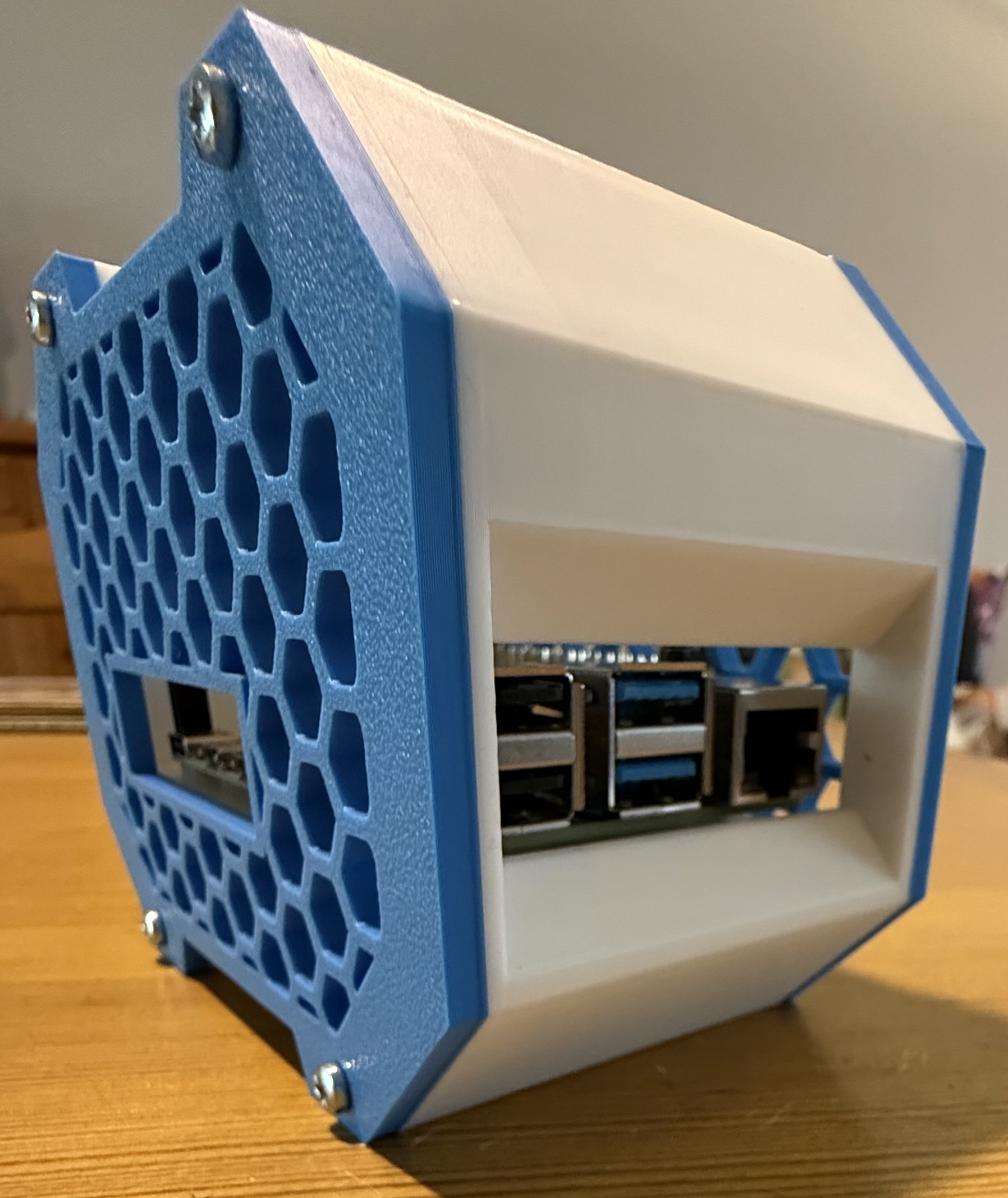
RaspberryPi 4 case from printables.com

Go on, release your inner creativity and treat yourself to a 3D printer, you won’t regret it and it’ll help you bring to life all of those radio projects you’ve dreamt of doing but, never got round to starting.

3: An AllStarLink Node
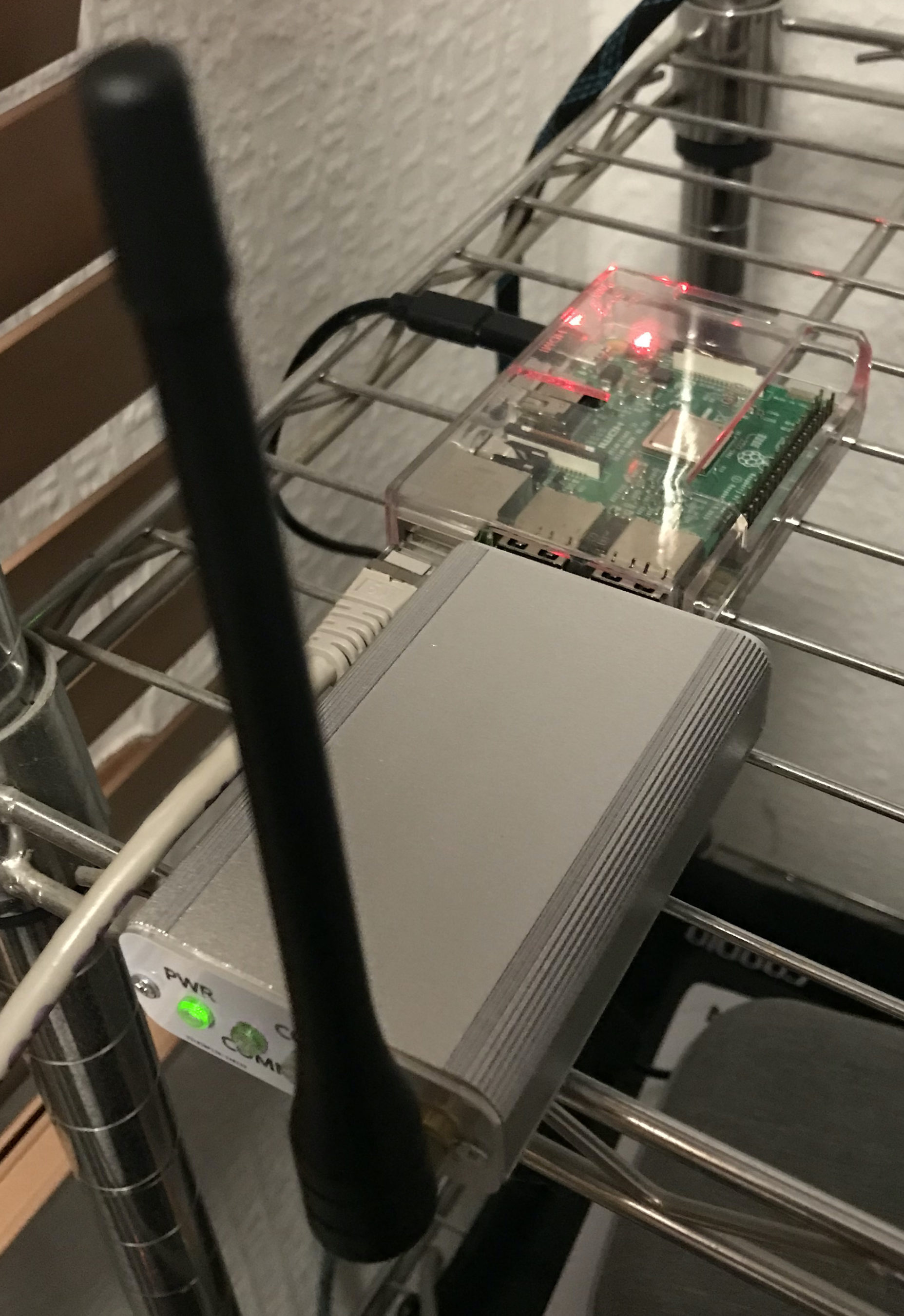
M0AW AllStarLink Node 61928 sitting on the equipment rack

Many people say that using VOIP over the internet isn’t real radio, I know because I used to be one of those people however, it has become an invaluable resource for keeping in touch with people all over the world.

Being part of an online HAM Radio Community it’s important that as a group we are able to talk to each other regardless of where we live, what bands we have access to and whether there is any propagation.

The AllStarLink (ASL) network gives global FM quality audio no matter where you are in the world. We use it daily for our breakfast net, general chatter throughout the day and even hold a weekly Matrix ASL Net on a Thursday evening.

Using our VHF/UHF handhelds (Real Radios!) and an easy to make AllStarLink Node we’re able to join in with the conversation regardless of propagation, licence type or distance, it really is great for bringing people together.

With devices like the SHARI and AIOC board now being readily available for minimal cost it really is very easy to get onto the AllStarLink network and talk to people even if you live in an antenna restricted location.

Why be alone when you can use the Matrix ASL node ( 642332 ) and join in the conversation.

4: Node-Red

M0AWS - Updated NodeRed QO-100 Dashboard with PTT button
M0AWS – Updated NodeRed QO-100 Dashboard with PTT button

Node-Red is a low-code programming tool for event-driven applications.

Node-RED’s goal is to enable anyone to build applications that collect, transform and visualise their data; building flows that can automate their world. Its low-code nature makes it accessible to users of any background, whether for home automation, industrial control systems or anything in between.

I’ve been using Node-Red for a number of years now and have developed a suite of web app’s that control and monitor just about every aspect of my Amateur Radio hobby and IT infrastructure.

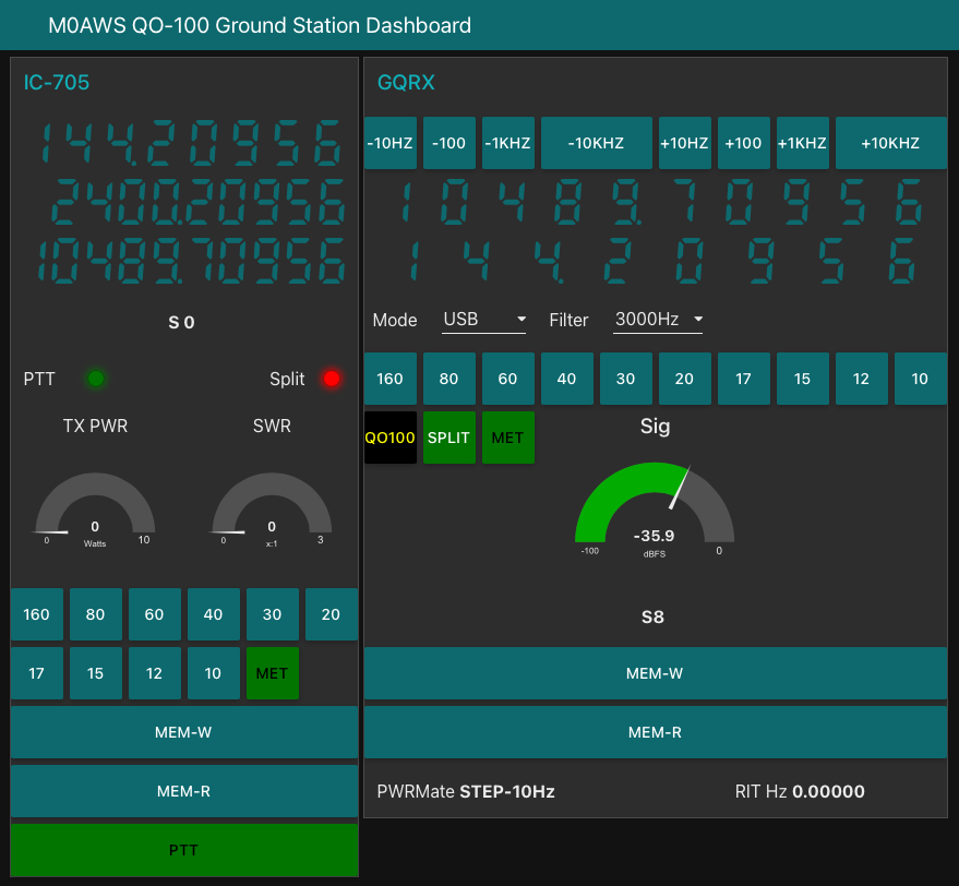
Node-Red forms an integral part of my QO-100 Satellite Ground Station providing control of both the uplink and down link radios whilst synchronising the VFO’s, controlling filter selection and more, all from one simple to use interface using nothing more than a web browser.

It doesn’t stop there, my AllStarLink (ASL) nodes are also managed through a user friendly Node-Red Dashboard that removes all the need for technical know how and makes ASL node management as simple as clicking on a button to connect or disconnect to the many global networks.

Much of this functionality is achieved without writing a single line of code. If you can use a mouse, drag and drop objects on the screen you can develop Node-Red web app’s, it really is that easy.

M0AWS Interactive Log Flow

It doesn’t end there, Node-Red is great for presenting data in easy to digest formats.

Whether it be HAM Radio Log data presented on an interactive world map or monitoring of your server, RaspberryPi, virtual machine or UPS using gauges and graphs, this can all be achieved easily with nothing more than a mouse. There’s no need to spend hours writing thousands of lines of code, just drag and drop a few nodes onto the screen and join them up. You’ll be amazed how easy it is.
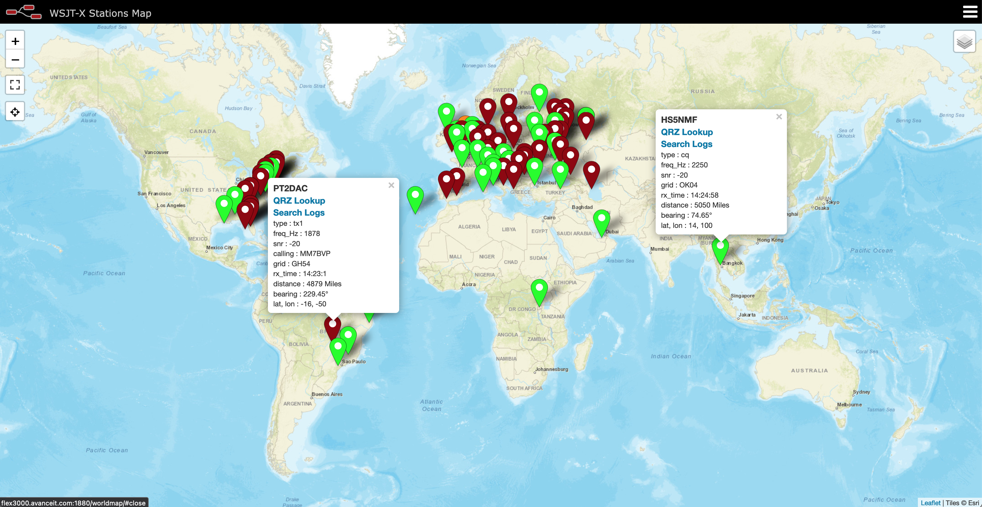
I believe every Amateur Radio enthusiast should have Node-Red available in their radio shack. It’s easy to install on your RaspberryPi 4 or 5, Linux or Windows PC and Apple Mac with the same great functionality available on all platforms.

Once you’ve developed your first web app you’ll suddenly find a million more ideas will come into your head and before you know it, you’ll be where I am today with Node-Red at the centre of your radio hobby.

5: A Hermes Lite 2 HF SDR Transceiver

For years I used black box HF radios from the big 3 manufacturers along with the odd radio from the smaller enterprises like TenTec but, they all had their foibles and there was often nothing I could do about it.

My last acquisition from the big 3 was a Yaesu FTDX10, a competent hybrid SDR radio with a good receiver however, the menu system is terrible, the button layout not much better and the user experience not as good as it could be. Of course the software is closed source so there is nothing you can do about it. The radio did its job but, it wasn’t fun to use, it wasn’t what I really wanted and it didn’t put a smile on my face.

I looked at moving to software defined radios (SDR) but, with prices in the many thousands of pounds bracket and the software being closed source I came to the conclusion that they wouldn’t give me what I really wanted either.

So what was it that I was searching for?

Thinking long and hard about it I came to the conclusion that what I really wanted was a radio that gave me the same satisfaction that OpenSource software has given me for decades, namely an HF radio that I have complete control over, from the hardware through to the software and everything in between.

I wanted something that I could tailor to my exact needs. Something that was built using open hardware and open software, something where if I wasn’t happy with it I could change it, improve it and do the things I wanted with it.

At this point my search for the ideal radio headed in a completely different direction.
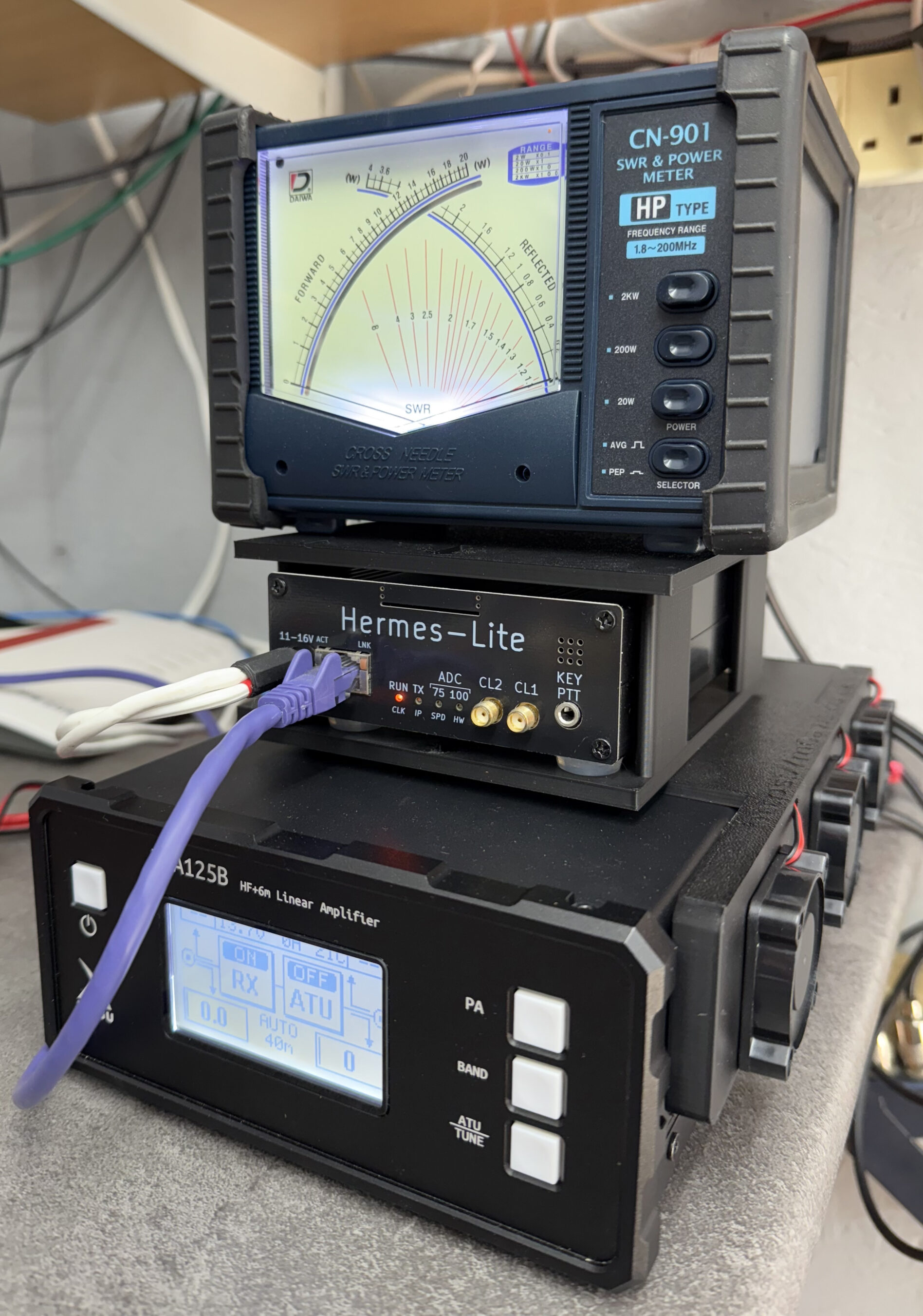
Xiegu XPA125b Cooler with Hermes Lite 2 cradle - front view
Xiegu XPA125b Cooler with Hermes Lite 2 cradle – front view

The Hermes Lite 2 SDR HF Transceiver (HL2) has been around for a number of years. I was first introduced to it by Michael, DK1MI and then Roger, G8VLR via the Matrix. Both Michael and Roger use the HL2 on a regular basis and have often waxed lyrical about how good it is.

Being designed by radio amateurs for radio amateurs it’s based on an open architecture from the ground up. Being an OpenSource junky this really appealed to me and as I looked deeper into it from both a hardware and software point of view I soon realised that it had the potential to be exactly what I was looking for.

It wasn’t long before I found myself on the Makerfabs website placing an order for the HL2 mainboard, filter board, I/O board and case. A couple of weeks later it arrived and I dived head first into the SDR rabbit hole.

2 years later and the HL2 has become my main HF radio in the shack. Partnered with a Xiegu XPA125B amplifier and PiHPSDR software running on my Kubuntu Linux PC it is everything I have been looking for in an HF radio.

I’ve made modifications to the software to suit my operating style and needs with the user interface being exactly how I want it, no unnecessary buttons or knobs, just the controls that I use on a daily basis cleanly placed in a logical, easy to use layout, the way I want it.

My understanding of software defined radio and how it works has improved a hundred fold. Having access to the software and being able to go through the code and understand the architecture has been an interesting journey and one that has enhanced my radio enjoyment considerably. I now have a smile on my face every time I go on air.

Do I miss the FTDX10?

No, not in the slightest!

So, those are the 5 things that I feel have revolutionised my radio amateur hobby and made it a more enjoyable experience. I’m sure over time I will add to this list as I venture down future rabbit holes in our wonderful radio hobby.

More soon …

Using Node-Red to build interactive log maps

I’ve not been on the radio much over the last few weeks as I’ve had my head down other radio related rabbit holes.

One of the rabbit holes is a Node-Red project to make my online logs a little more interactive. For sometime now my logs have been displayed on my website as nicely formatted, searchable HTML pages however, they don’t really allow the viewer (myself included) to see the global coverage of all the contacts so, I decided to write a Node-Red flow that would do just that.

M0AWS Interactive Log Flow

The flow itself isn’t too complicated and basically consists of reading in the individual ADIF formatted log files, processing the data and then sending the data in the correct format to the map node for display.

I’ve had to write a few functions to handle the processing of the ADIF formatted data but, these aren’t particularly complex and are fairly easy to understand even if like me, you’re not a Javascript programmer.

The flow is working perfectly however, I’m in the process of reworking the format generic payload function to reduce the amount of code and make it more efficient.

M0AWS SSB / CW / FreeDV Interactive Log World Map
M0AWS Interactive Log Map Layers Menu


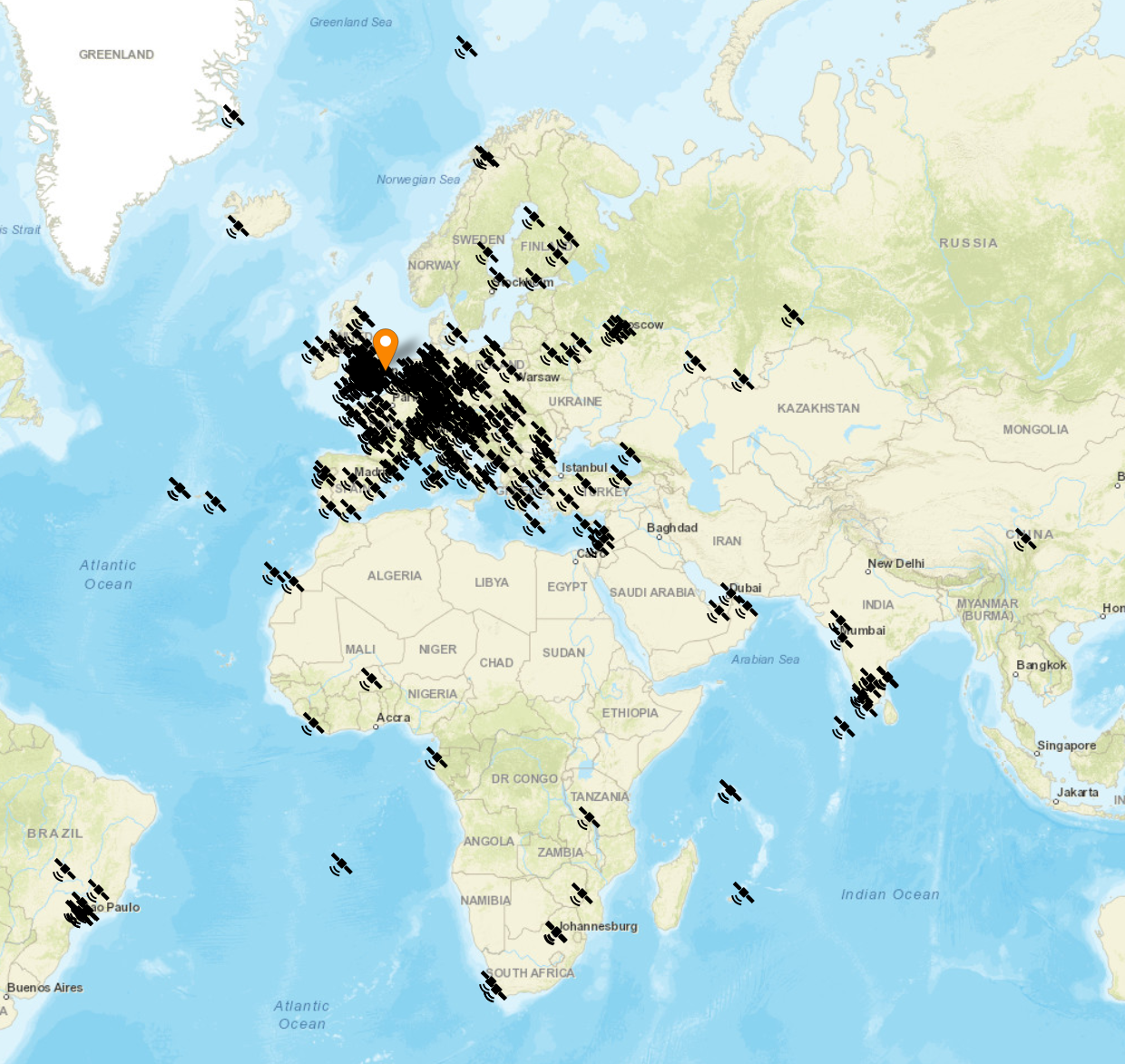
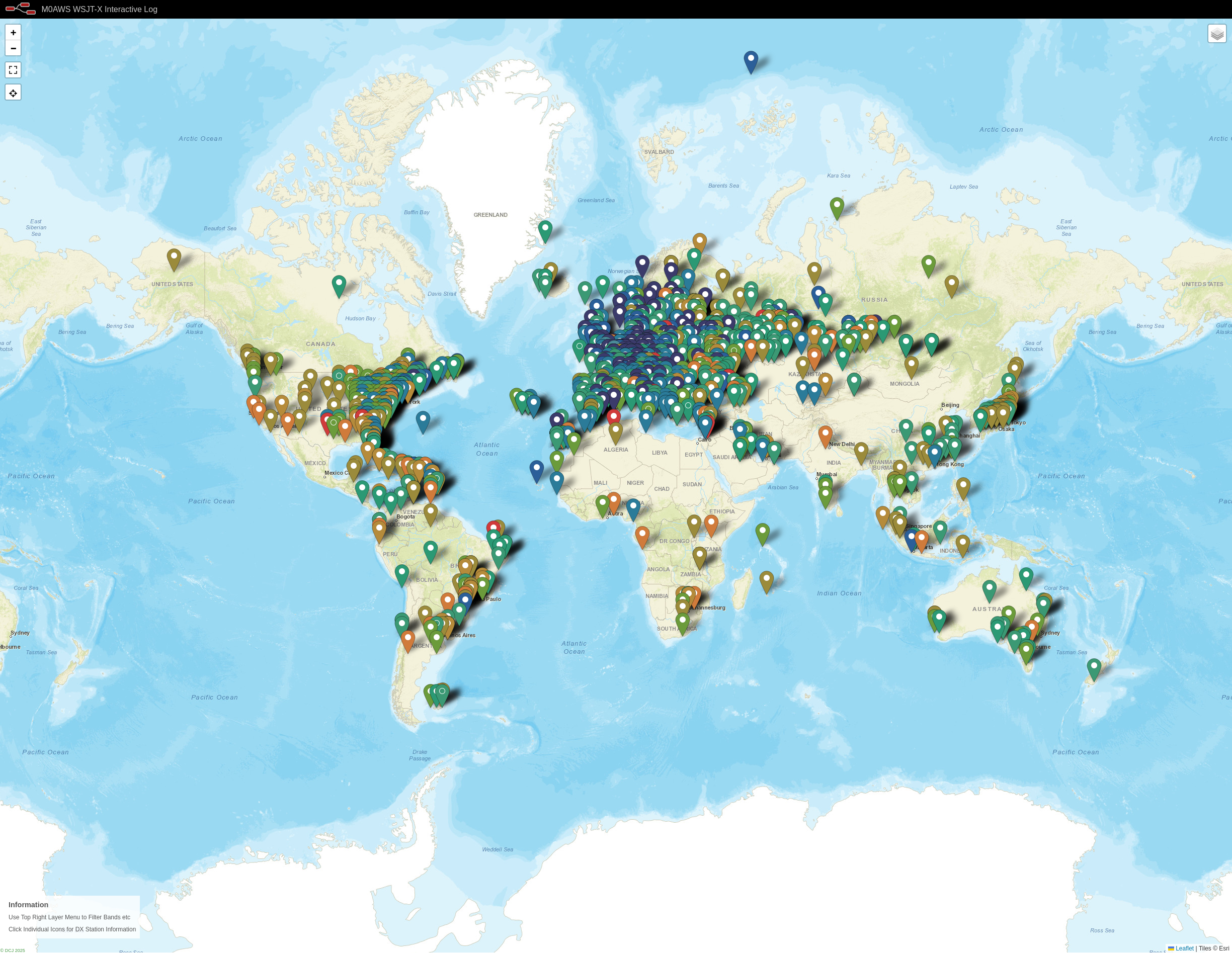
The flow generates two maps, one for voice / CW /Satellite contacts and the other for WSJT-X FT4/8 contacts. Every pin on the map is colour coded by band with satellite contacts being denoted by a satellite icon.

Each pin / icon on the map is clickable and reveals the data of the QSO being displayed.

In the top right-hand corner of the map there is a drop down layer menu that allows the viewer to filter by band thus reducing the number of icons on the screen at any one time.

Seeing the data presented on a map really brings my logs alive. An example of this is that I had no idea I’d worked so many stations in India on the QO-100 Satellite.

The small icons in the pins show a microphone for SSB/FM/FreeDV contacts and a downwards pointing triangle in a box for CW contacts. Sadly I couldn’t find a Morse key icon in the collection available.

M0AWS filtered view of QO-100 Satellite contacts

I only use FT4/8 for testing new antenna designs however, it’s interesting to see the global coverage accomplished with this weak signal mode.

M0AWS WSJT-X FT4/8 Interactive Log World Map

Once I’ve finished rewriting the format generic payload function I will make the flow available for download here so that others can also create an interactive view of their radio logs.

If you want to have a look at the maps and try them out for yourself, they are available under the Logs menu above.

This Node-Red instance is running in a virtual machine (VM) on a 16GB RAM RaspberryPi 5 that is also running a number of other VMs at the same time so, it’s safe to say it’s not heavy on CPU and will run on the older Pi4 as well.

More soon …

Updates to my install-pihpsdr.sh script

Over the last few weeks I’ve been working on my install-pihpsdr script to build a version of the DL1YCF PiHPSDR fork that will work with the Adalm Pluo, Pluto+ and LibreSDR transceivers.

Since I don’t own any of these devices, Steve M0XVT has loaned me his Adalm Pluto and LibreSDR devices to test with.

Initially neither of the devices would work with the PiHPSDR build that my script was creating. After some investigation I found this was due to the fact that the developer build script was only building the SOAPYSDR library, it wasn’t building the modules for each device type.

This was easily fixed by adding some extra code that would build the necessary SOAPYSDR modules so that the devices were discovered on the local LAN.

Since I had the devices to hand I took the opportunity to test the updated build script on a number of Linux Distro’s that I have to hand.

PiHPSDR running on Linuxmint 22.1 Cinnamon Edition using the LibreSDR transceiver

I tested the updated build script on Kubuntu 22.04LTS, Linuxmint 22.1 Cinnamon Edition and RaspberryPi 4/5 running the latest RaspberryPi OS 64bit version.

These all worked great with the transceivers and will now make a great platform for QO-100 stations that use either the Adalm Pluto, Pluto+ or LibreSDR devices.

Of course this build of PiHPSDR will also work with the Hermes Lite 2 and RadioBerry devices that I use most of the time in my own radio shack.

The updated PiHPSDR install script can be downloaded from my original blog article on the subject that is located here: https://m0aws.co.uk/?p=3686

The updated build script will most likely work on most Debian based Linux distro’s and build a working version of PiHPSDR. If you find a distro where you have problems please email me and let me know the details and I’ll happily look at the issue and try to resolve it.

Thanks to Steve for the loan of his precious SDR transceivers, I had a lot of fun with them!

More soon …
Node-RED Dashboard 2.0

Ever since I started using Node-RED I’ve been using the standard node-red-dashboard set of user interface (UI) nodes to build my numerous dashboards to enhance my radio hobby and add new functionality to the operating of the station. The series of UI nodes are very simple to use and have served me well however, they are no longer being developed and are now deprecated in the overall Node-RED project.

To this end flowfuse.com have stepped up to the mark and developed Dashboard 2.0. This new series of UI nodes brings a new, more modern look and feel to the Node-RED dashboard along with some new functionality.

Short video showing the new Node-RED Dashboard 2.0 Linear gauge

I’ve only just started investigating Dashboard 2.0 but, it’s proving to be fairly easy to use. The short video clip above shows an S-Meter display developed using Dashboard 2.0 for my FTDX10 transceiver.

Full instructions on how to install and configure Node-RED Dashboard 2.0 can be found on the flowfuse.com website.

Be aware though, Node-RED dashboards developed using Dashboard 1.0 will not work under Dashboard 2.0, you will have to import the old v1.0 flow(s) and manually go through them and change all the UI nodes to new Dashboard 2.0 nodes. Since some of the new nodes work differently to the old nodes you’ll also find you will need to make code changes to get the same/similar functionality.

I’m finding it easier not to import old flows but to recreate them afresh under Dashboard 2.0 using the old flow version for reference.

Overtime I will migrate my dashboards over to the new 2.0 version however, this is going to be a lot of work, especially in the case of my QO-100 Ground Station Dashboard as it contains a considerable number of UI nodes, and will take a fair amount of time to migrate.

I’ll document my findings as I go as I’m sure there will be a few trials and tribulations along the way.

Thanks to Neil, G7UFO for pointing me to the new Dashboard 2.0 information.

More soon …
Deep Dive – Node-RED QO-100 Satellite Ground Station Dashboard

Following on from my article about my QO-100 Satellite Ground Station Complete Build, this article goes into some detail on the Node-RED section of the build and how I put together my QO-100 Satellite Ground Station Dashboard web app.

The Node-RED project has grown organically as I used the QO-100 satellite over time. Initially this started out as a simple project to synchronise the transmit and receive VFO’s so that the SDR receiver always tracked the IC-705 transmitter.

Over time I added more and more functionality until the QO-100 Ground Station Dashboard became the beast it is today.

M0AWS QO-100 ground Station Control Dashboard built using Node-RED.
M0AWS QO-100 Ground Station Control Dashboard built using Node-RED.

Looking at the dashboard web app it looks relatively simple in that it reflects a lot of the functionality that the two radio devices already have in their own rights however, bringing this together is actually more complicated than it first appears.

Starting at the beginning I use FLRig to connect to the IC-705. The connection can be via USB or LAN/Wifi, it makes no difference. Node-RED gains CAT control of the IC-705 via XMLRPC on port 12345 to FLRig.

To control the SDR receiver I use GQRX SDR software and connect to it using RIGCTL on GQRX port 7356 from Node-RED. These two methods of connectivity work well and enables full control of the two radios.

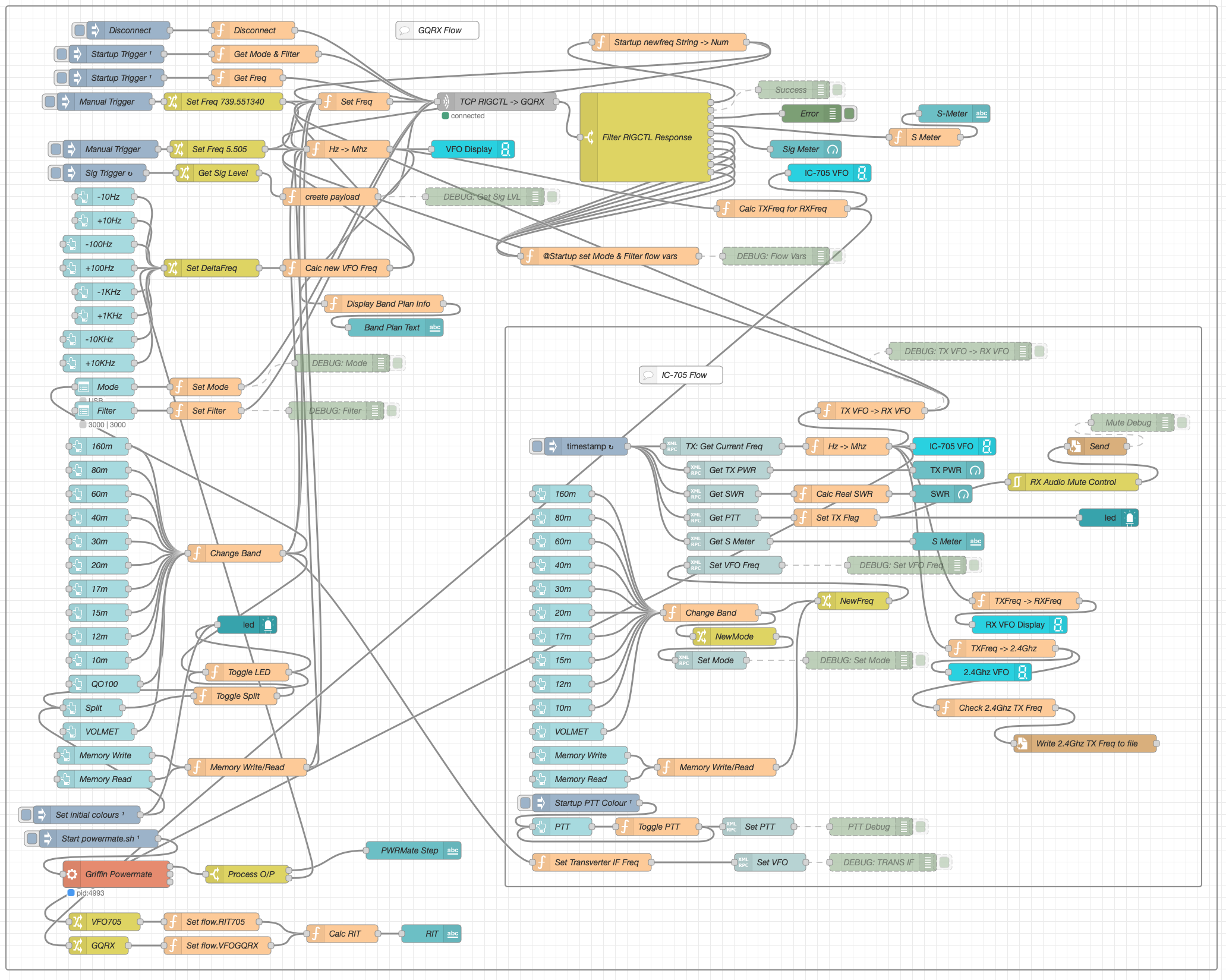
M0AWS Node-RED QO-100 Ground Station Dashboard - 12/06/24
M0AWS Node-RED QO-100 Ground Station Dashboard Flow as of 12/06/24

The complete flow above looks rather daunting initially however, breaking it down into its constituent parts makes it much easier to understand.

There are two sections to the flow, the GQRX control which is the more complex of the two flows and the comparatively simple IC-705 section of the flow. These two flows could be broken down further into smaller flows and spread across multiple projects using inter-flow links however, I found it much easier from a debug point of view to have the entire flow in one Node-RED project.

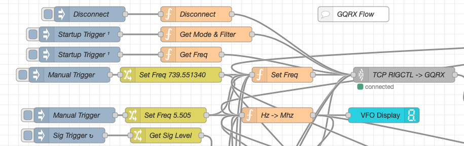
Breaking down the flow further the GQRX startup section (shown below) establishes communication with the GQRX SDR software via TCP/IP and gets the initial mode and filter settings from the SDR software. This information is then used to populate the dashboard web app.

M0AWS - Node-RED QO-100 Ground Station Dashboard - GQRX Startup
M0AWS Node-RED QO-100 Ground Station Dashboard – GQRX Startup Flow

The startup triggers fire just once at initial startup of Node-RED so it’s important that the SDR device is plugged into the PC at boot time.

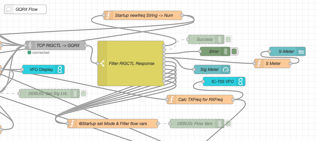
All the startup triggers feed information into the RIGCTL section of the GQRX flow. This section of the flow (shown below) passes all the commands onto the GQRX SDR software to control the SDR receiver.

M0AWS - QO-100 Ground Station Dashboard - GQRX RIGCTL flow
M0AWS Node-RED QO-100 Ground Station Dashboard – GQRX RIGCTL Flow

The TCP RIGCTL -> GQRX node is a standard TCP Request node that is configured to talk to the GQRX software on the defined IP Address and Port as configured in the GQRX setup. The output from this node then goes into the Filter RIGCTL Response node that processes the corresponding reply from GQRX for each message sent to it. Errors are trapped in the green Debug node and can be used for debugging.

The receive S Meter is also driven from the the output of the Filter RIGCTL Response node and passed onto the S Meter function for formatting before being passed through to the actual gauge on the dashboard.

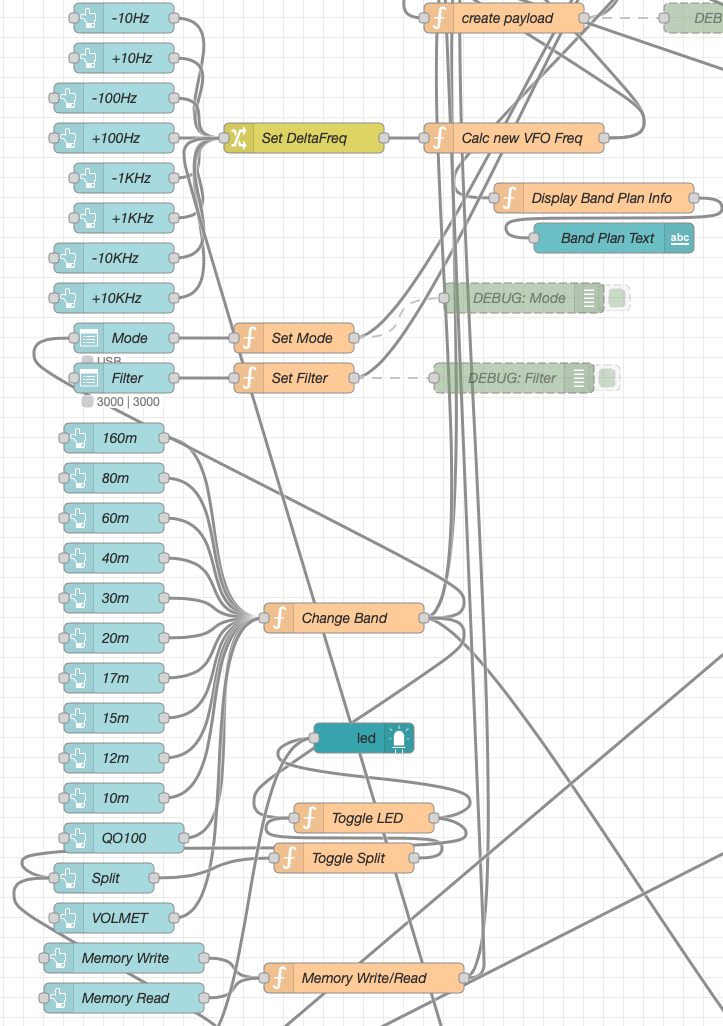
Continuing down the left hand side of the flow we move into the section where all the GQRX controls are defined.

M0AWS - QO-100 Ground Station Dashboard - GQRX Controls
M0AWS Node-RED QO-100 Ground Station Dashboard – GQRX Controls Flow

In this section we have the VFO step buttons that move the VFO up/down in steps of 10Hz to 10Khz. Each button press generates a value that is passed onto the Set DeltaFreq change node and then on to the Calc new VFO Freq function. From here the new VFO frequency is stored and passed onto the communications channel to send the new VFO frequency to the GQRX software.

The Mode and Filter nodes are simple drop down menus with predefined values that are used to change the mode and receive filter width of the SDR receiver.

Below are the HAM band selector buttons, each of these will use a similar process as detailed above to change the VFO frequency to a preset value on each of the HAM HF Bands.

The QO-100 button puts the transmit and receive VFO’s into synchro-mode so that the receive VFO follows the transmit VFO. It also sets the correct frequency in the 739Mhz band for the downlink from the LNB in GQRX SDR software and sets the IC-705 to the correct frequency in the 2m VHF HAM band to drive the 2.4Ghz up-converter.

The Split button allows the receive VFO to be moved away from the transmit VFO for split operation when in QO-100 mode. This allows for the receive VFO to be moved away so that you can RIT into slightly off frequency stations or to work split when working DXpedition stations.

The bottom two Memory buttons allow you to store the current receive frequency into a memory for later recall.

At the top right of this section of the flow there is a Display Band Plan Info function, this displays the band plan information for the QO-100 satellite in a small display field on the Dashboard as you tune across the transponder. Currently it only displays information for the satellite, at some point in the future I will add the necessary code to display band plan information for the HF bands too.

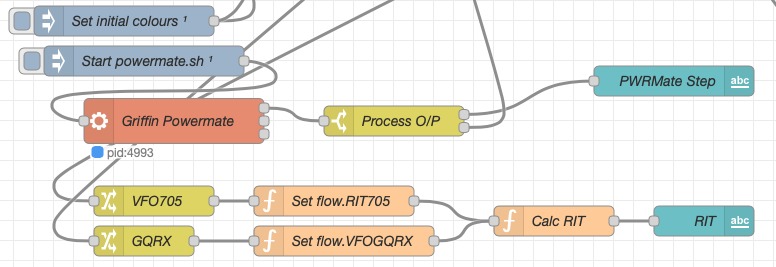
The final section of the GQRX flow (shown below) sets the initial button colours and starts the Powermate USB VFO knob flow. I’ve already written a detailed article on how this works here but, for completeness it is triggered a few seconds after startup (to allow the USB device to be found) and then starts the BASH script that is used to communicate with the USB device. The output of this is processed and passed back into the VFO control part of the flow so that the receive VFO can be manually altered when in split mode or in non-QO-100 mode.

M0AWS - QO-100 Ground Station Dashboard - Powermate VFO section
M0AWS Node-RED QO-100 Ground Station Dashboard – Powermate VFO Flow

The bottom flows in the image above set some flow variables that are used throughout the flow and then calculates and sets the RIT value on the dashboard display.

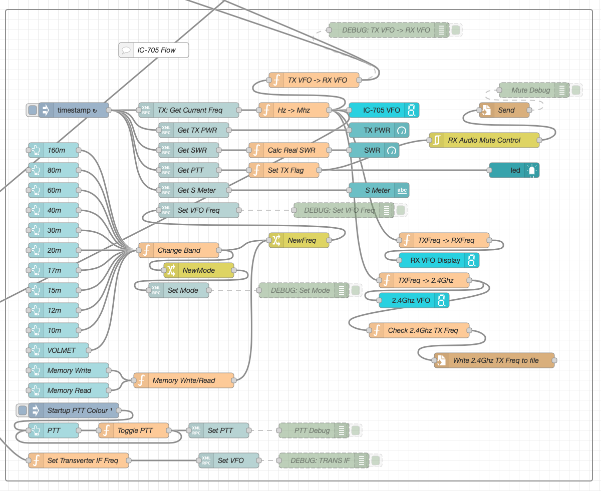
The final section of the flow is the IC-705 control flow. This is a relatively simple flow that is used to both send and receive data to/from the IC-705, process it and pass it on to the other parts of the flow as required.

M0AWS - QO-100 Ground Station Dashboard - IC-705 control flow
M0AWS Node-RED QO-100 Ground Station Dashboard – IC-705 Control Flow

The IC-705 flow is started via the timestamp trigger at the top left. This node is nothing more than a trigger that fires every 0.5 seconds so that the dashboard display is updated in near realtime. The flow is pretty self explanatory, in that it collects the current frequency, transmit power, SWR reading, PTT on/off status and S Meter reading each time it is triggered. This information is then processed and used to keep the dashboard display up to date and to provide VFO tracking information to the GQRX receive flow.

On the left are the buttons to change band on the IC-705 along with a button to tune to the VOLEMT on the 60m band. Once again there two memory buttons to save and recall the IC-705 VFO frequency.

The Startup PTT Colour trigger node sets the PTT button to green on startup. The PTT button changes to red during transmit and is controlled via the Toggle PTT function.

At the very bottom of the flow is the set transverter IF Freq function, this sets the IC-705 to a preselected frequency in the 2m HAM band when the dashboard is switched into QO-100 mode by pressing the QO-100 button.

On the right of the flow there is a standard file write node that writes the 2.4Ghz QO-100 uplink frequency each time it changes into a file that is used by my own logging software to add the uplink frequency into my log entries automatically. (Yes I wrote my own logging software!)

The RX Audio Mute Control filter node is used to reduce the receive volume during transmit when in QO-100 full duplex mode otherwise, the operator can get tongue tied hearing their own voice 250ms after they’ve spoken coming back from the satellite. This uses the pulse audio system found on the Linux platform. The audio is reduced to a level whereby it makes it much easier to talk but, you can still hear enough of your audio to ensure that you have a good, clean signal on the satellite.

As I said at the beginning of this article, this flow has grown organically over the last 12 months and has been a fun project to put together. I’ve had many people ask me how I have created the dashboard and whether they could do the same for their ground station. The simple answer is yes, you can use this flow with any kind of radio as long as it has the ability to be controlled via CAT/USB or TCP/IP using XMLRPC or RIGCTL.

To this end I include below an export of the complete flow that can be imported into your own Node-RED flow editor. You may need to make changes to it for it to work with your radio/SDR but, it shouldn’t take too much to complete. If like me you are using an IC-705 and any kind of SDR controlled by GQRX SDR software then it’s ready to go without any changes at all.


More soon …

The Matrix HAM Radio Community continues to grow

A couple of years ago I built a Matrix Synapse server and connected it to the decentralised global Matrix chat network that is federated world wide by enthusiasts who host their own Matrix servers. Due to the enthusiasm for a decentralised network the Matrix has grown exponentially and is now an established force in the world of Opensource global communication services.

When I built my server and configured it online my aim was to bring together an enthusiastic group of Radio Amateurs (Radio HAMs) who could build a friendly, welcoming community where people could share, learn and have fun with other liked minded individuals without all the nonsense you see on commercial social media platforms.

Overtime we’ve increased the number of rooms available in the HAM Radio space and the number of subjects covered. This has grown organically as our community has grown and we’ve ventured together into new areas of the hobby.

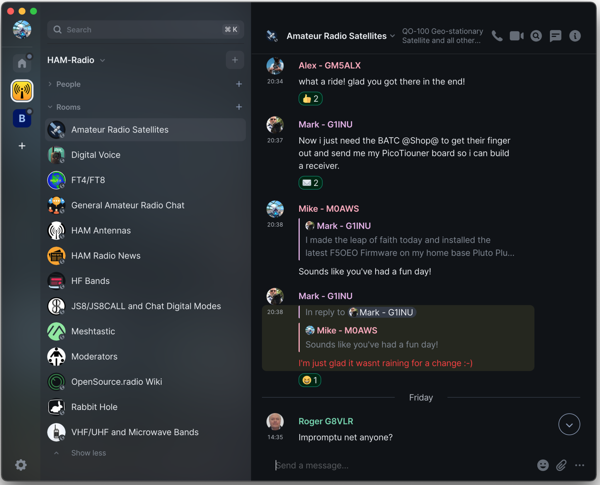
Global Matrix Ham Radio Space hosted on the M0AWS Matrix Server

From the community a number of projects have spawned including the Opensource.radio Wiki that Mike, DK1MI is sponsoring that aims to detail all the Opensource HAM Radio software, Hardware and projects in one centralised site on the internet. This is a great project and one I am very happy to contribute to.

Thanks to Mike, DK1MI we now also have our own Matrix AllStarLink node available. This is a great resource for the community as it is often not possible for all of us to communicate via the radio waves due to geo-location, time zones, local planning regulations etc. Having this 24/7 internet based resource makes it a lot easier for the community to chat at any time even when propagation on the HF bands isn’t in our favour.

Mike, DK1MI has written an excellent article on the Matrix AllStarNode and more, I highly recommend you take a look at it.

We also have a very active satellite room with regular nets on the QO-100 satellite. With such a great range of rooms and subjects there’s plenty to read and talk about with the community.

If you fancy being part of this growing, enthusiastic group of Radio Amateurs and Short Wave Listeners (SWLs) then click on the link below and come and say hello, a warm welcome awaits!

https://m0aws.co.uk/matrix

More soon …
QO-100 Satellite Ground Station Complete Build

I get quite a few emails from readers of my blog asking how my QO-100 satellite station is put together and so, I thought perhaps now is a good time to put together an article detailing the complete build.

My QO-100 satellite ground station is built around my little Icom IC-705 QRP transceiver, it’s a great little rig and is ideal for the purpose of driving a 2.4Ghz transverter/up-converter.

Of course all the software used for the project is Opensource and freely available on the internet.

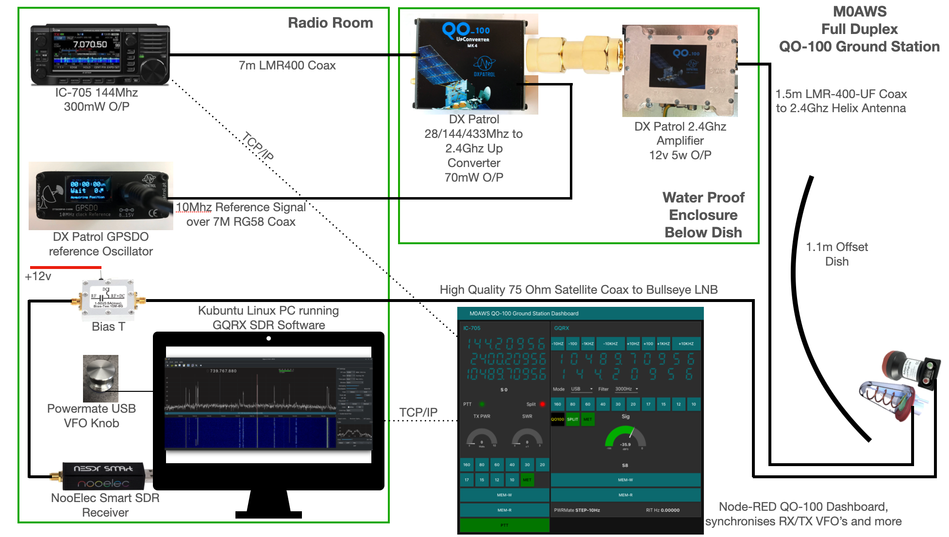
M0AWS QO-100 Ground Station Build Visual
M0AWS QO-100 Ground Station Build Visual (Click to Enlarge)

The station comprises of the following building blocks:

  • Icom IC-705 Transceiver
  • DXPatrol 28/144/433Mhz to 2.4Ghz Up-Converter
  • DXPatrol GPSDO Reference Oscillator
  • DXPatrol 2.4Ghz 5/12w Amplifier
  • Nolle Engineering 2.2 turn 2.4Ghz IceCone Helix Antenna
  • 1.1m (110cm) Off-set Dish
  • Bullseye 10Ghz LNB
  • Bias-T to feed 12v to LNB
  • NooElec SmartSDR Receiver
  • PC Running Kubuntu Linux Operating System
  • GQRX SDR Opensource Software
  • Griffin Powermate USB VFO Knob
  • QO-100 Ground Station Dashboard developed using Node-RED
  • LMR400-UF/RG58 Coax Cable
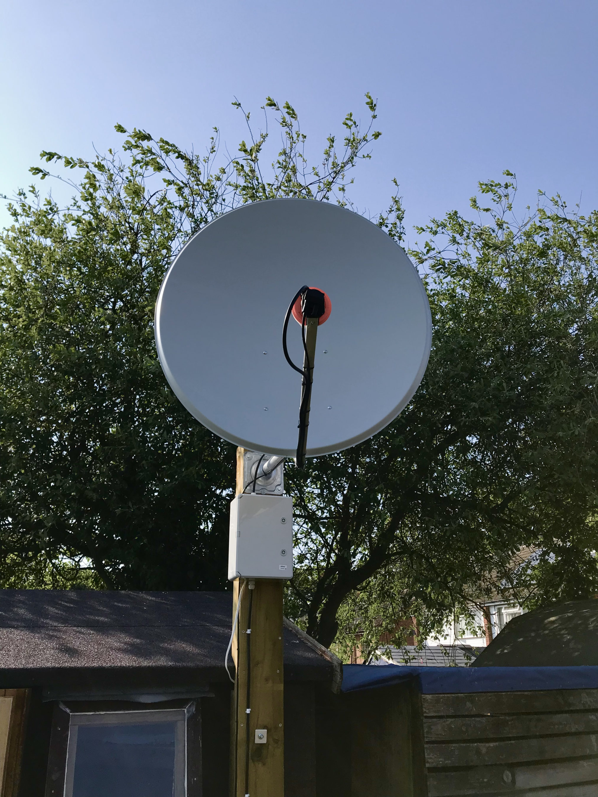
M0AWS QO-100 1.1m off-set Dish and IceCone Helix antenna ground station
M0AWS QO-100 1.1m (110cm) off-set Dish with IceCone Helix antenna and Bullseye LNB.

To get a good clear view of the QO-100 satellite I have the dish mount 3.2m above the ground. This keeps it well clear of anyone walking past in the garden and beams the signal up at an angle of 26.2 degrees keeping well clear of neighbouring gardens.

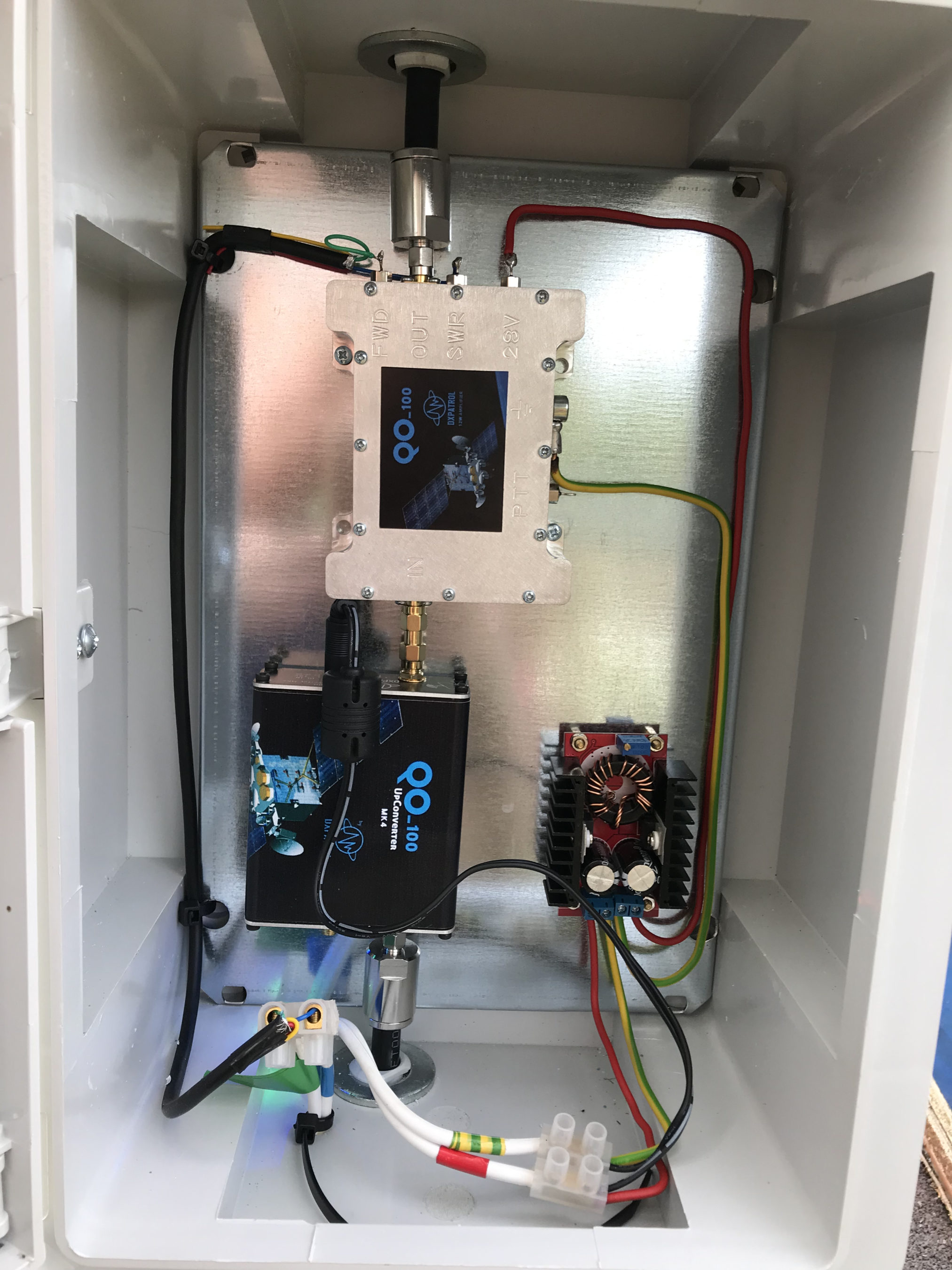
The waterproof enclosure below the dish houses all the 2.4Ghz equipment so that the distance between the feed point and the amplifier are kept to a minimum.

The DXPatrol amplifier is spec’d to run at 28v/12w or 12v/5w, I found that running it at 28v produced too much output for the satellite and would cause the LEILA alarm on the satellite to trip constantly. Running the amp at 12v with a maximum of 5w output (average 2.5-3.5w) is more than enough for me to have a 5/9+10 signal on the transponder.

The large 1.1m dish gives me quite an advantage on receive enabling me to hear the very weak stations with ease compared to other stations.

2.4Ghz ground station enclosure ready for testing

The photo above shows the 2.4Ghz equipment mounted in the waterproof enclosure below the dish. This photo was taken during the initial build phase before I rewired it so, the amplifier is shown connected to the 28v feed. To rewire the amp to 12v was just a matter of removing the 28v converter and connecting the amp directly to the 12v feed instead. This reduced the output from a maximum of 12w down to a maximum of 5w giving a much better (considerate) level on the satellite.

It’s important to keep all interconnects as short as possible as at 2.4Ghz it is very easy to build up a lot of loss between devices.

For the connection from the IC-705 to the 2.4Ghz Up-Converter I used a 7m run of
LMR-400 coax cable. The IC-705 is set to put out just 300mW on 144Mhz up to the 2.4Ghz converter and so it’s important to use a good quality coax cable.

Once again the output from the 2.4Ghz amplifier uses 1.5m of LMR-400-UF coax cable to feed up to the 2.2 turn Icecone Helix Antenna mounted on the dish. This keeps loss to a minimum and is well worth the investment.

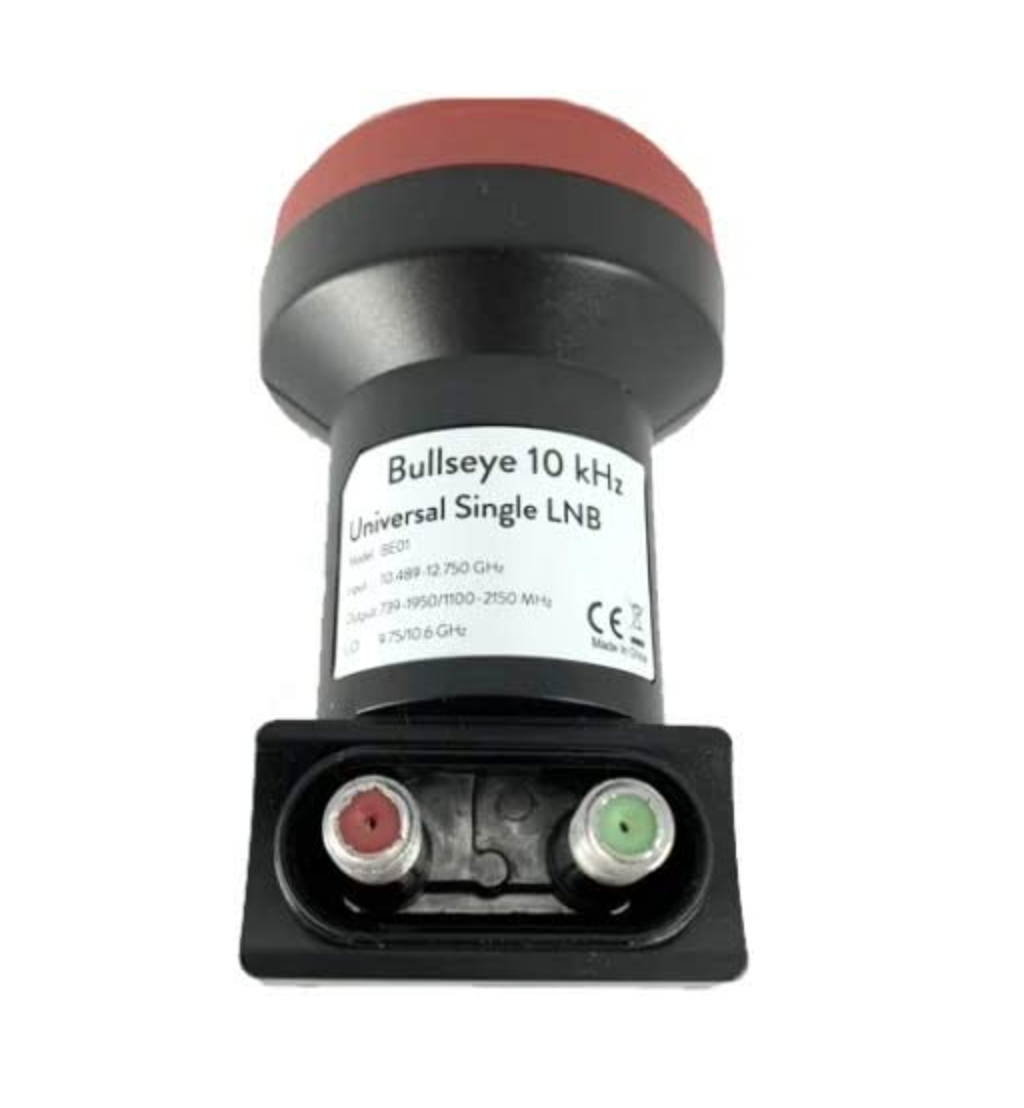
Bullseye 10Khz High Stability Unversal Single LNB for 10.489-12.750Ghz

The receive path starts with a Bullseye LNB, this is a high gain LNB that is probably one of the best you could use for QO-100 operations. It’s fairly stable frequency wise but, does drift a little in the summer months with the high temperature changes but, overall it really is a very good LNB.

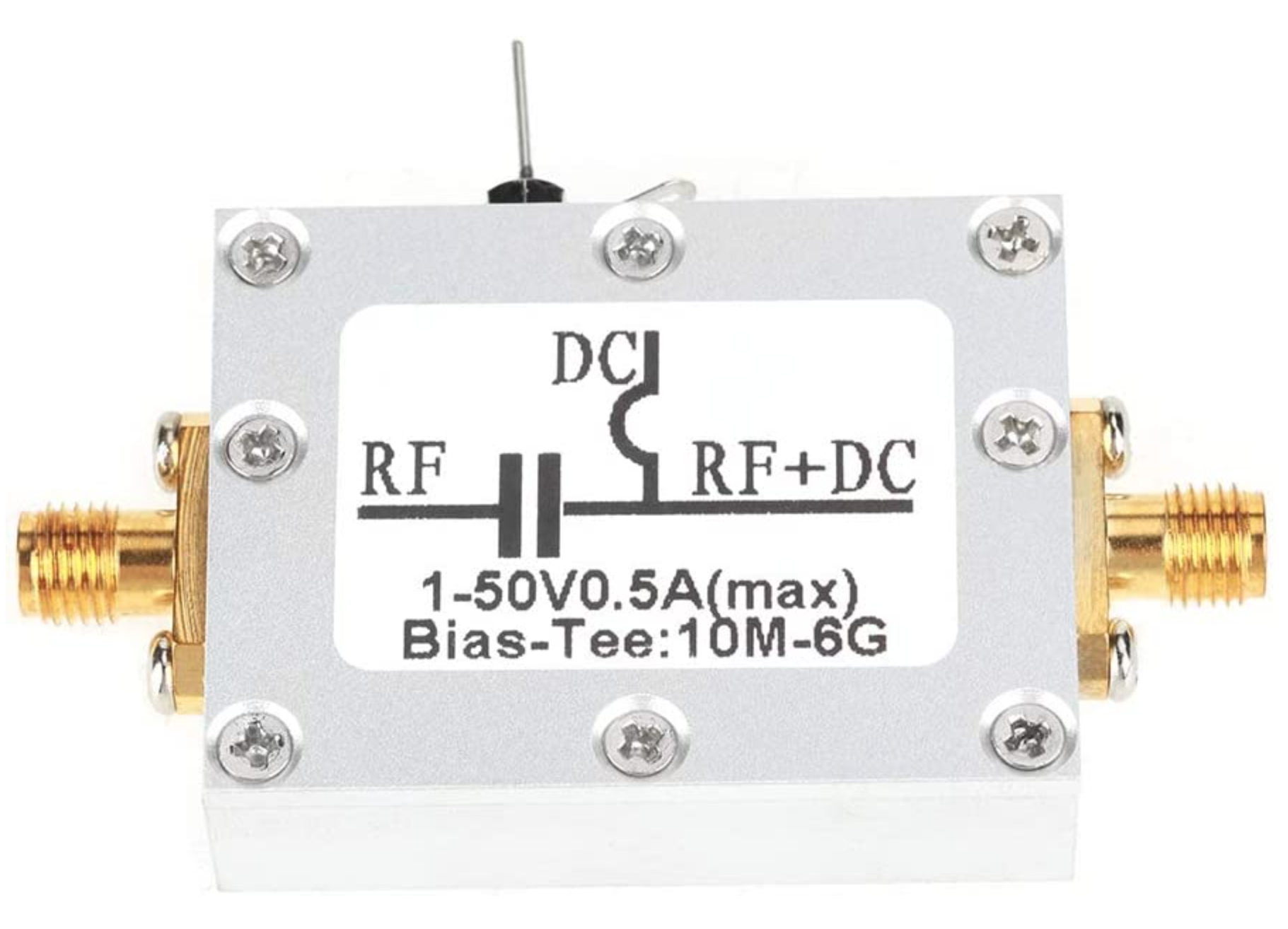
The 12v feed to the LNB is via the coax and is injected by the Bias-T device that is in the radio shack. This 12v feed powers the LNA and associated electronics in the LNB to provide a gain of 50-60dB.

Bias-T to inject 12v feed into the coax for the Bullseye LNB

From the Bias-T the coax comes down to the NooElec SmartSDR receiver. This is a really cheap SDR device (<£35 on Amazon) based on the RTL-SDR device but, it works incredibly well. I originally used a Funcube Dongle Pro+ for the receive side however, it really didn’t handle large signals very well and there was a lot of signal ghosting so, I swapped it out for the NooElec SDR and haven’t looked back since.

The NooElec SmartSDR is controlled via the excellent Opensource software GQRX SDR. I’ve been using GQRX SDR for some years now and it’s proven itself to be extremely stable and reliable with support for a good number of SDR devices.

To enhance the operation of the SDR device I have added a Griffin Powermate VFO knob to the build. This is an old USB device that I originally purchased to control my Flex3000 transceiver but, since I sold that many moons ago I decided to use it as a VFO knob in my QO-100 ground station. Details on how I got it working with the station are detailed in this blog article.

Having the need for full duplex operation on the satellite this complicates things when it comes to VFO tracking and general control of the two radios involved in the solution and so I set about creating a QO-100 Dashboard using the great Node-RED graphical programming environment to create a web app that simplifies the management of the entire setup.

M0AWS QO-100 ground Station Control Dashboard built using Node-RED.

The QO-100 Dashboard synchronises the transmit and receive VFO’s, enables split operation so that you can transmit and receive on different frequencies at the same time and a whole host of other things using very little code. Most of the functionality is created using standard Node-RED nodes. More info on Node-RED can be found on the Opensource.radio Wiki or from the menu’s above.

I’ll be publishing an article all about the QO-100 Dashboard in the very near future along with a downloadable flow file.

I’m extremely pleased with how well the ground station works and have had well in excess of 500 QSO’s on the QO-100 satellite over the last last year.

More soon …
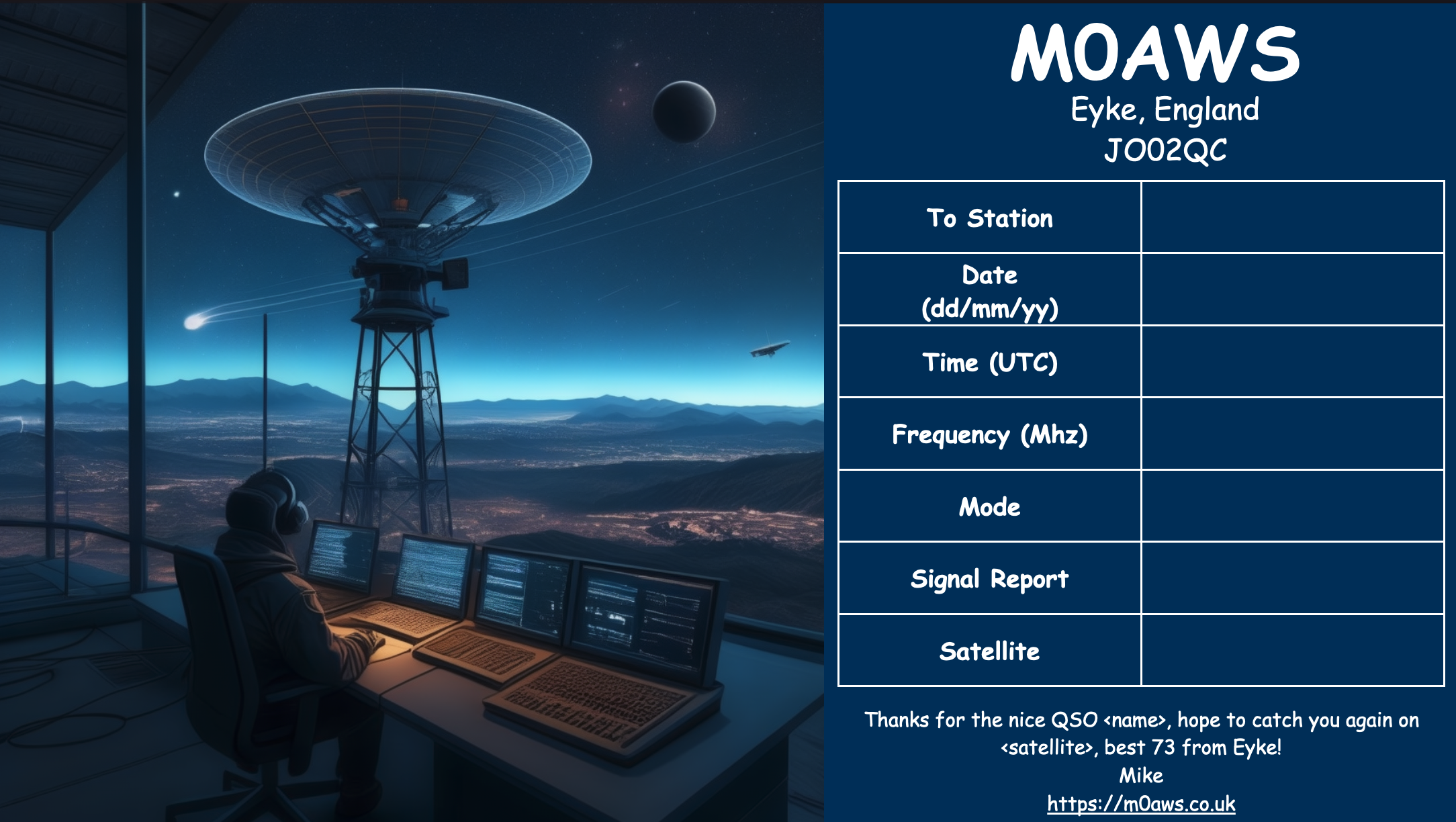
Using AI to generate modern QSL Cards

With the recent explosion of artificial intelligence (AI) art generators that are making the news of late for all the wrong reasons, I decided to see if I could put it to good use and design some futuristic QSL cards.

Having recently been contacted by the Special Callsigns QSL Manager and being advised that there were 18 QSL cards waiting for me, I decided it was time to create some QSL cards of my own for future use.

Having never used any form of online AI and not having any artistic abilities I was amazed how easy it was to create images using nothing more than a paragraph or so of text to describe what it was I wanted to create.

Since all the QSL cards I received were for contacts on the QO-100 satellite, I set out to create a visually futuristic QSL card that was based around a radio HAM operator and satellite communications.

M0AWS - 1st attempt to create a futuristic QSL card using AI Art
M0AWS – 1st attempt at creating a futuristic QSL card image using AI Art

To my surprise the results of my first image generation were surprisingly good. The AI generated an image that resembled the simple text that I entered, although I never requested a one legged HAM operator!

Pleased with my very first attempt I gradually improved the description of what I was looking for, adding more and more detail to the text and including things that I wanted to see in the image. Over a fairly short period of time this approach started to generate some very interesting images.

With each iteration I gradually got closer to what I was trying to achieve but, never quite got exactly what I wanted so, I decided to rewrite the descriptive text adding even more information than before. The text was now a full blown paragraph with quite specific things described including the angle at which the scene was being viewed from.

The other option I wanted to try out was the theme functionality that the AI offered. This allows you to set a theme for the image from things like steampunk, cartoon, manga, real world and many more. The results were quite impressive and added yet another angle to the image generation.

I disappeared down the theme AI Art generation rabbit hole for quite some time and generated some very interesting and fun results. The best by far though was the Thunderbirds themed image, this did put a smile on my face!

M0AWS - AI Art QSL Thunderbirds Themed
M0AWS – AI Art QSL Thunderbirds Themed

At the other end of the spectrum I tried the Salvador Dalli theme, it produced an image that was very like the work of the famous artist but, wasn’t quite what I was looking for.

M0AWS - AI Art QSL Salvador Dalli Themed
M0AWS – AI Art QSL Salvador Dalli Themed

After much fun I eventually settled on the image I was after, a futuristic scene of a radio HAM with a satellite ground station over looking a mountain range and city below.

M0AWS Satellite QSL Card generated using online AI

I’m really pleased with the results from my ventures into AI generated art. The next challenge is to create a QSL card for HF bands Contacts.

More soon …
Update to my NodeRed QO-100 Dashboard

Ever since my QO-100 ground station has been operational I’ve been using my NodeRed QO-100 Dashboard to control my IC-705 and GQRX SDR software to drive my NooElec SmartSDR receiver. This gives me a full duplex ground station with both transmit and receive VFO’s synchronised.

This solution has worked incredibly well from the outset and over time I’ve added extra functionality that I’ve found to be useful to enhance the overall setup.

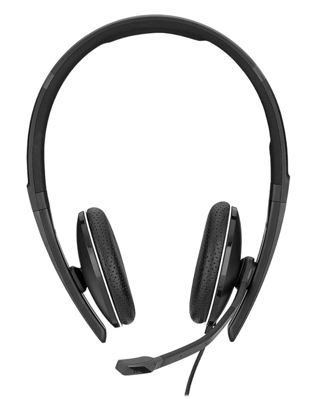
The latest addition to the ground station solution is a Sennheiser Headset that I picked up for just £56 on Amazon (Much cheaper than the Heil equivalents at the HAM stores!) and have found it to be excellent. The audio quality from both the mic and the headphones is extremely good whilst being light and comfortable to wear for extended periods.

M0AWS - Sennheiser SC 165
M0AWS – Sennheiser SC 165 Headset

To incorporate this into the ground station the headset is connected to my Kubuntu PC and the audio chain to the IC-705 is sent wirelessly using the latest version of WFView. This works extremely well. The receive audio comes directly from the GQRX SDR software to the headphones so that I have a full duplex headset combination.

Audio routing is done via pulse audio on the Kubuntu PC and is very easy to setup.

Since I no longer have a mic connected to the IC-705 directly I found that I needed a way to operate the PTT wirelessly and this is where the latest addition to my NodeRed QO-100 Dashboard comes in.

Adding a little functionality to the NodeRed flow I was able to create a button that toggles the IC-705 PTT state on and off giving me the ability to easily switch between receive and transmit using a simple XMLRPC node without the need for a physical PTT button.

M0AWS - Additional NodeRed PTT Flow
M0AWS – Additional NodeRed PTT Flow

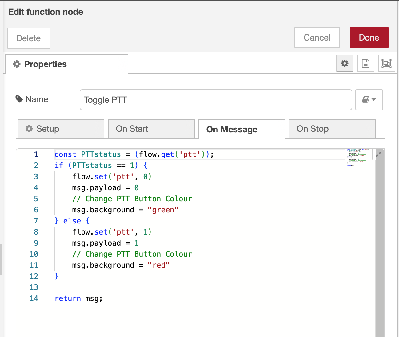
The PTT state and PTT button colour change is handled by the Toggle PTT function node shown in the above flow. The code to do this is relatively simple as shown below.

M0AWS - NodeRed Toggle PTT Function to change button colour
M0AWS – NodeRed Toggle PTT Function to change button colour

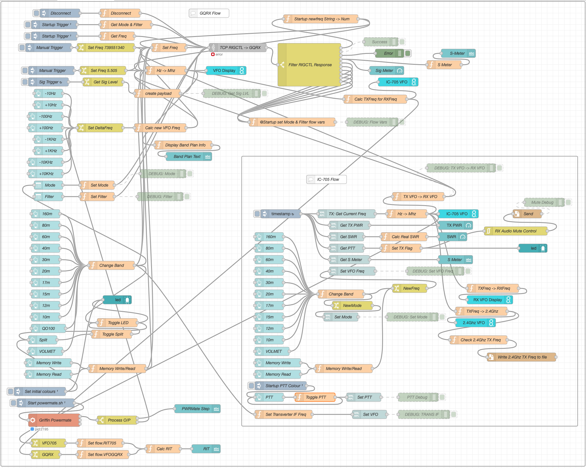
The entire QO-100 Dashboard flow has grown somewhat from it’s initial conception but, it provides all the functionality that I require to operate a full duplex station on the QO-100 satellite.

M0AWS - NodeRed QO-100 Dashboard complete flow
M0AWS – NodeRed QO-100 Dashboard complete flow

This simple but, effective PTT solution works great and leaves me hands free whilst talking on the satellite or the HF bands when using the IC-705. This also means that when using my IC-705 it only requires the coax to be connected, everything else is done via Wifi keeping things nice and tidy in the radio shack.

M0AWS - Updated NodeRed QO-100 Dashboard with PTT button
M0AWS – Updated NodeRed QO-100 Dashboard with PTT button

The image above shows the QO-100 ground station in receive cycle with the RX/TX VFO’s in split mode as the DX station was slightly off frequency to me. The PTT button goes red when in TX mode just like the split button shown above for visual reference.

As you can probably tell, I’m a huge fan of NodeRed and have put together quite a few projects using it, including my HF Bands Live Monitoring web page.

More soon …
The Art of Articulation

Since I’ve been using my Icom IC-705 on the QO-100 satellite I’ve been getting no end of unsolicited great audio reports with one Op even saying I have the best audio he’s ever heard on the satellite.

Most people are surprised when I tell them that I am using the stock fist mic that comes with the radio. It’s nothing special, in fact it’s rather cheap and plastic, not particularly good quality however, it does seem to have a good sounding mic insert.

The other great thing about the IC-705 is that it has a two channel parametric equaliser built into the radio. Many people don’t realise this and miss out on the massive improvement they can make to their transmitted audio with just a few simple adjustments.

The stock fist mic has a very flat response across the audio frequency range out of the box and doesn’t sound particularly inspiring. Many see this as a negative and often just replace the mic with either a headset (probably from Heil), a boom mic (again probably from Heil) or another, better quality fist mic. All of these options cost varying amounts of money when in reality none of them are necessary.

Starting from a flat audio response is actually a good thing as it makes the equaliser adjustments more pronounced, making it easier to adjust the settings to suit your voice.

We all have different voices but, there is one thing that is pretty much the same for everyone and that’s the frequency range in which the articulation of the words and sounds we make can be found. It’s this part of the voice that is often lacking when we struggle to understand what the DX station is saying.

It’s become common place on the HAM bands these days for stations to boost the bass frequencies and reduce the mid and high frequencies with the net result of a horrible bass ringing sound and muddy mid range often making it very difficult to understand what is being said.

Having spent some considerable time watching the great videos on audio from the late Bob Heil, K9EID it’s clear that the most important frequencies to enhance are those around 2.5khz as this is where all the articulation is in the human voice.

To this end I set about setting up the audio on my IC-705 QRP radio so that my voice sounded such that it is easy to comprehend even in the most difficult of situations on air. This doesn’t mean that it has to be very harsh and overly bright, quite the opposite in that to be heard clearly in all conditions on air one’s audio needs to be balanced across the frequency range with an enhancement in the 2.5Khz frequency range.

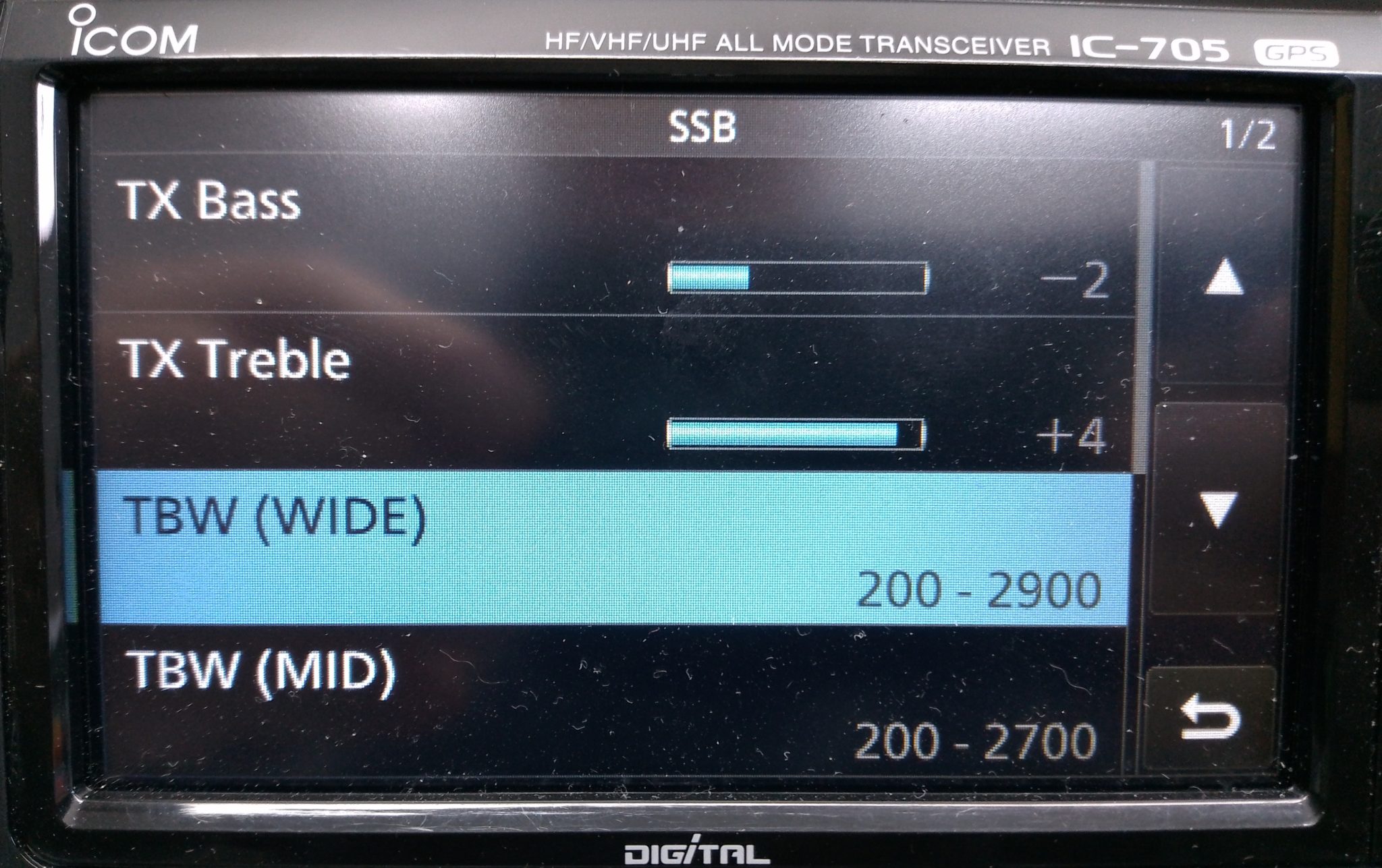
M0AWS IC-705 Transmit audio settings - part 1
M0AWS IC-705 Transmit audio settings – part 1

To reduce the unwanted, muddy bass the first thing to do is change the transmit bandwidth for the “Wide” setting to 200-2900Hz. This will cut off the bottom 100Hz from the voice reducing the overall bass output from the standard fist mic that comes with the radio. This will ensure a 2700Hz wide SSB signal, the recommended max for QO-100 operations and the preferred bandwidth on the HF bands.

On top of this I made a further reduction of 2dB on the TX Bass setting to help balance out the overall audio response of the mic insert.

Next I set about enhancing the higher frequency response of the mic insert and found that it required an increase of 4dB to bring out the articulation of my voice. This enhanced my audio considerably compared to the standard output from the fist mic and improved the intelligibility of my voice considerably, especially in difficult band conditions.

To complete the setup I set the compression to 3 and mic gain to 35 so that the overall drive level is increased slightly giving a greater average output from the radio.

M0AWS IC-705 Audio Settings - part 2
M0AWS IC-705 Audio Settings – part 2

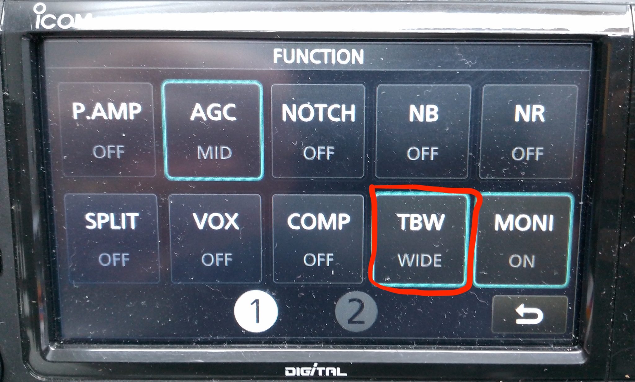
Once I’d got the audio setup correctly I enabled the configuration by setting the Transmit Bandwidth (TBW) to the “Wide” config in the IC-705 Function menu so that the correct settings were made active.

Ever since making these relatively easy changes I have had no end of unsolicited great audio reports from stations asking me what mic I am using and how I’ve managed to get such good audio from the IC-705. Many are surprised that I am using the OEM fist mic that comes with the radio and I’m sure there are those who don’t believe me!

Of course all voices are slightly different and these settings may not be perfect for your voice but, all those that have tried these settings have told me that their audio sounds better than ever and that DX stations often comment on how good their audio is.

I also went through the same exercise with my Yaesu FTDX10 with it’s standard fist mic and again achieved excellent results with it’s 3 channel parametric equaliser. I’ll go through the somewhat more complicated setup for the FTDX10 in another article soon.