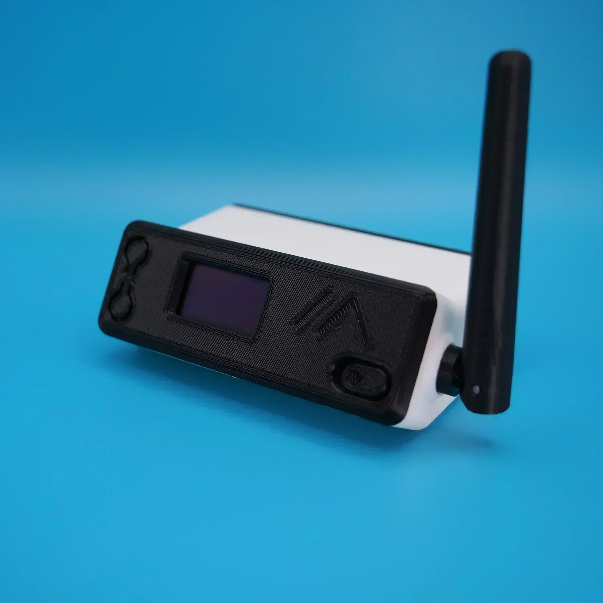
Rescuing a Bricked Pluto+

I’ve not written an article on the blog for a while now mainly because I’ve not had anything interesting to write about.

Today that changed, as I had a fun little project to dive into.

Steve, M0XVT sent me his Pluto+ SDR transceiver after his rather unsuccessful attempt at updating the firmware. Long story short, he somehow managed to brick the Pluto+ rendering it completely useless.

Not having a Pluto+ myself I’ve never actually played with one before and so this was new and exciting. I have, however played with Steve’s LibreSDR which is a later iteration of the Pluto+ and so, I had an idea of what I was getting into.

Firstly, how do you know when you have bricked your Pluto+?

Fortunately the Pluto+ device is actually quite clever and will inform you when it is bricked. The first sign you will notice is that you can no longer connect to the device using a USB connection to the data socket. The second sign is that when you take the top off the case you’ll notice that the blue LED is off and the green LED is on constantly. These are both classic signs that the device is bricked and needs rescuing

So, how do we rescue a bricked Pluto+?

Firstly, disconnect all cables and power to the device, it needs to be in a powered down state. Next remove the top of the case completely.

Unlike the LibreSDR the Pluto+ doesn’t boot from SD card so, we have to tell it that we want to boot it from an SD card. This is done by shorting the 3v3 and SD-H pins together using a jumper as shown in the photo below. (Black Jumper)

Pluto+ 3v3 and SD-H pins shorted together by black jumper

I believe that the v1 version of the Pluto+ has 1.8v instead of 3.3v, if this is the case on your device just short the SD-H pin to the 1v8 pin instead.

Next we need to make sure that the URST pin is connected to the MIO46 pin as shown by the green jumper in the image above. I put the jumper into this position as I am going to be using firmware that has ethernet support built in. If you want to load the official firmware then you will need to connect the URST pin to the MIO52 pin instead.

Next we need to load the new firmware onto an appropriate SD card. I’m using the F5OEO firmware that has ethernet support with DHCP built in. You can get the firmware from this Github link.

Whilst the firmware is downloading, insert your SD card into your PC and format it using a FAT32 filesystem.

Once the firmware has downloaded, unzip the file and save the contents of the zip file to a directory. Using your favourite file manager or in the case of a Linux junkie like me, the command line, copy the contents of the sdimg folder into the root of the SD card.

Note: That’s copy of the contents of the sdimg folder, not the folder itself.

Make sure to eject your SD card safely before removing it from your PC to ensure you don’t corrupt the contents.

Insert the SD card into the Pluto+ (it’s still powered down at this point with the top off).

Plug the USB A end of the USB cable into your PC but, do not plug the micro USB end into the Pluto+ just yet!

Now this is the tricky part, you need to hold down the DFU Button on the Pluto+ PCB (It’s behind the professor image on the PCB) whilst inserting the micro-USB plug into the DATA port of the Pluto+.

Once you see that the green and blue LED lights come on permanently, let go of the DFU Button and let the Pluto+ boot from the SD card. A short while afterwards the green LED should start flashing, this means your Pluto+ is alive again and has booted from the SD card.

At this point it’s important not to unplug the USB cable and not to remove the SD card from the device, we’re only half way there!

After a little more time the Pluto+ will appear in your file manager as a drive called PlutoSDR, navigate to this drive using your favourite file manager.

At the same time, open another window in your file manager and navigate to the folder where you saved the files from the Zip file. In this directory you will see the following two files:

boot.frm
pluto.frm

Copy these two files from the directory where you saved them into the root of the PlutoSDR drive.

Once this is complete, eject the PlutoSDR drive safely.

The green LED will now start blinking, don’t do anything, just leave everything as it is and the device will now create a new boot image on it’s own built in storage.

This process will take about 5mins so, go grab a cold beer, glass of wine or anything else that takes your fancy, sit back and relax.

Eventually the green LED will stop flashing, wait another minute or so for the process to fully complete.

If the PlutoSDR drive has reappeared in your file manager, safely remove the drive from your file manager and unplug the micro USB connector from the Pluto+ powering it down.

It’s now important to remove the 3v3 to SD-H jumper as we no longer need to boot from SD card.

You can now refit the top cover and the 4 screws and put the case back together. Connect an ethernet cable and micro USB cable to the DATA port and wait.

After about 10-15 seconds the green LED should flash and your Pluto+ is now no longer bricked and ready for use once more.

You can SSH to your Pluto+ using the normal Linux SSH command logging in as root with a password of analog.

If you have PiHPSDR installed and compiled with the SOAPYSDR library and modules (See my article on how to do this easily) you can now start it and connect to your Pluto+ device as normal.
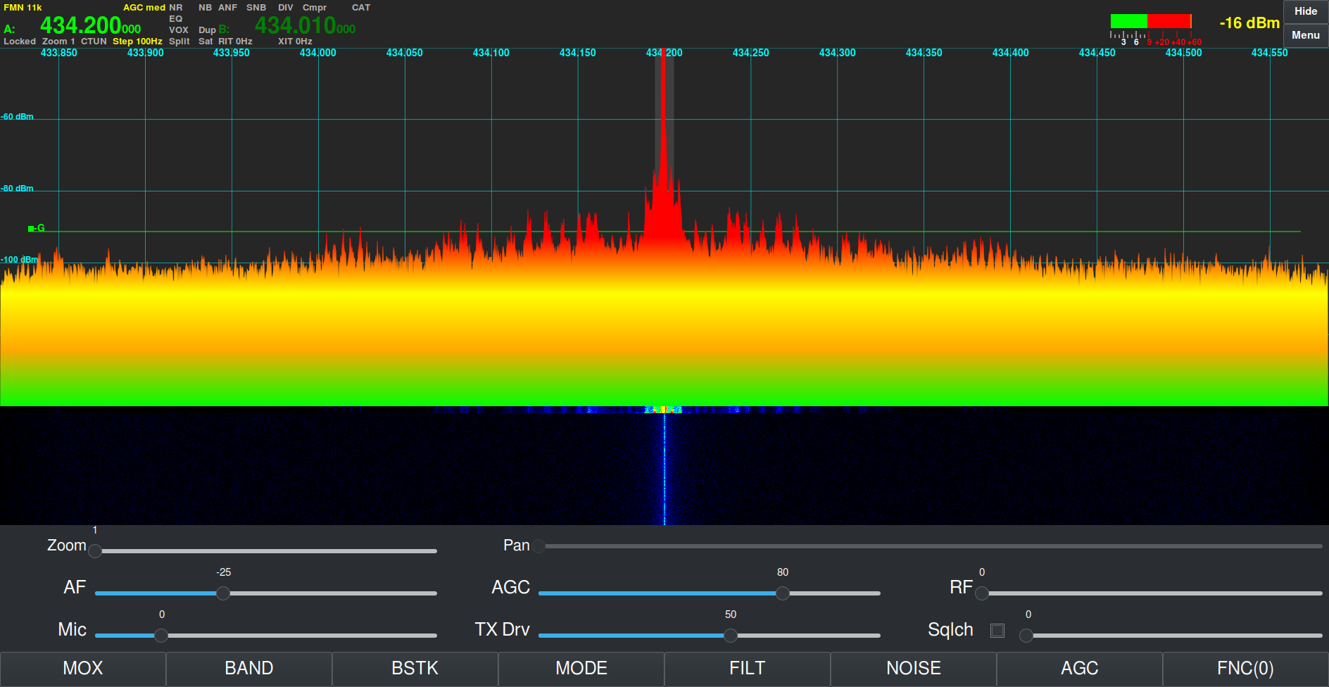
Steve's rescued Pluto+ receiving a signal from my AllStarLink node in PiHPSDR
Steve’s rescued Pluto+ receiving a signal on the 70cm band

This same procedure can be used on Linux, Mac, Windows and RaspberryPi, it is not platform dependent.

If you want your Pluto+ to always boot from the SD card, you can leave the 3v3 pin connected to the SD-H pin permanently.

More soon ….

RadioBerry Software Install

For the last week or so I’ve been playing with a RadioBerry HAT for my RaspberryPi computer. The RadioBerry is a cut down version of the Hermes Lite 2 with just 20mW output power and separate TX and RX antenna ports. It’s a really neat little package that sits on top of a RaspberryPi4/5 and creates a neat little HF transceiver.

RadioBerry HAT
RadioBerry HAT

I initially started with the RadioBerry HAT on my Pi5 but, I soon realised that the software really doesn’t work well at all on the Pi5. I’m not 100% sure as to why but, for some reason it holds one core at 100% continuously. It seems that the RadioBerry software is single threaded. The end result is that on the Pi5 you cannot use a sample rate above 9600 before the IQ stream starts to stutter.

By contrast, installing the RadioBerry software onto a Pi4 it performs perfectly upto the maximum sample rate of 384000 without any stuttering. I’ll need to spend some time going through the source code to try and determine why it doesn’t work correctly on a Pi5.

Whilst going through the source I discovered that the developer has put some code in that collects data from the running computer and sends it to the developer’s website. Some of this data is then made public via his website, http://www.pa3gsb.nl/radioberry/api/read.php

One of the things displayed on the website is the Mac address of the RaspberryPi on which the RadioBerry is running. This is a security risk and should never be done!

The most annoying thing is that this is done without authorisation. The installation doesn’t state that it’s going to collect data every time you start your RaspberryPi computer nor does it offer the ability to opt out. It also doesn’t inform the user that it’s going to pass the data on to a third party. In some cases it even collects HAM Radio Callsign and location data and displays it on a public website, a clear breach of the UK/European Data Protection Law.

Finding spyware in open source software is really poor and something most open source developers would never consider doing.

To this end I have disabled the spyware in the version of the RadioBerry software that I am using and am making it available to everyone else to use via this blog.

So, to install the RadioBerry software you just need to download the installation script and run it in a terminal on your RaspberryPi computer.

The script will download the modified source code, compile it and install it on your RaspberryPi ready for you to use.


I encourage everyone that downloads the script and the source code to take a look at it and ensure you are happy with it. It’s important to know what you are running on your computer and what it does.

You can find the spyware code in the register.c file (It’s all commented out with “//” marks). The function now doesn’t pass any data at all to the public website.

I hope some of my readers who are experimenting with the RadioBerry transceiver find this useful.

I will soon be publishing an article on an enhanced version of PiHPSDR from DL1YCF to use with the the RadioBerry to complete the project.

Important Update:

There is an issue with the RadioBerry code that renders it useless if you use a kernel later than the version shown below:

Linux Radioberry 6.6.51+rpt-rpi-v8 #1 SMP PREEMPT Debian 1:6.6.51-1+rpt3 (2024-10-08) aarch64 GNU/Linux

Updating the O/S Kernel to any version later than the version shown above will stop the RadioBerry software from working. Recompiling of the code also fails due to the Kernel update and at the time of writing this cannot be fixed without a code rewrite by the original developer.

I also recommend that once you have built a working RadioBerry on a RaspberryPi 4 you should disable the automatic updates of the O/S to stop the system from failing in the future.

You can disable the automatic updates by entering the following commands into a terminal:

sudo systemctl disable apt-daily.service
sudo systemctl disable apt-daily.timer

sudo systemctl disable apt-daily-upgrade.timer
sudo systemctl disable apt-daily-upgrade.service

You can check the version of the kernel you have installed using the following command in a terminal:

uname -a

Hopefully this will help anyone that is having issues with their RadioBerry after an O/S update.

More soon …

Loading Meshtastic Firmware onto Heltec ESP32 v3 Devices

The loading of the Meshtastic firmware on the Heltec ESP32 v3 devices is really simple if done via a Linux PC/RaspberryPi. There are of course other ways to load the firmware using a web browser that supports USB/Serial devices and this method is preferred by many however, being a Linux command line junkie I far prefer the simplicity of using the Linux command line to do the job.

So, how much experience with the Linux command line do you need?

In all honesty none at all. If you know how to use copy and paste then all you have to do is follow the simple steps I’ve detailed below. In reality it will only take a few minutes to do so, don’t be put off by the long article, I’ve just tried to cover everything and provide screen shots along the way.

To get started fire up your Linux PC/RaspberryPi and get yourself to the desktop. Next you will need to open a Linux command line terminal. This is often just called “Terminal” on most Linux desktop installations.

The first thing you need to do is check to see if you have python3 installed. This is done using the following command:

python3 --version

Running the above command you should see a result something like what is shown below.

Python3 command showing installed version

Next we need to check if pip3 is installed using the following command:

pip3 --version

If pip3 is installed then you should get a result similar to that shown below.

Pip3 command showing installed version

If your computer doesn’t have Python3 or Pip3 installed they can be easily installed from the command line. To install Python3 enter the following command into your terminal:

sudo apt install python3

You will be asked to enter your login password and then the installation will begin. You should see output in your terminal similar to that shown below.

Installing python3
Installing python3

To install Pip3 enter the following command into your terminal:

sudo apt-get install python3-pip

This will detail a long list of packages that will be installed on your computer, Enter Y to answer Yes and let the packages install.

M0AWS - Installing Pip3
M0AWS – Installing Pip3

You will see many messages scroll up the terminal screen such as getting, selecting, preparing, unpacking and setting up, this is all normal.

Once Pip3 is installed you should be dropped back at the command line with a terminal screen that looks something like the one below.

M0AWS - Pip3 install complete
M0AWS – Pip3 install complete

At this point you will now have Python3 and Pip3 available on your computer.

You are now ready to install the tool we are going to use to check your Meshtastic device is connected to your PC and install the firmware to it. (Do not connect your Meshtastic device to your PC just yet!)

Run the following command in your terminal to install the ESP Tool:

pip3 install --upgrade esptool

You will see an output from the installation process similar to that shown below.

M0AWS - Installing the ESP Tool
M0AWS – Installing the ESP Tool

Now that we have the ESP tool installed plug your Meshtastic device into your USB port on your computer and then run the following command to interrogate the device to find out what kind of device it is.

esptool chip_id

You should see the information about your device that looks similar to that shown below. This information should confirm the device type (ESP32) and which USB port it is connected on (/dev/tty/USB0).

M0AWS - Expected output from the ESPTool command showing device information
M0AWS – Expected output from the ESPTool command showing device information

Once you have this information you will need to download the firmware for your device from Github using the following URL:

https://github.com/meshtastic/firmware/releases

At the time of writing this I downloaded and used the v2.2.22.404d firmware which I have found to be extremely reliable.

In your terminal you now need to change directory (cd) into the Downloads directory where your downloaded firmware should be. (If you downloaded your firmware into another directory then you will need to cd into that directory). Use the following command to change directory into the Downloads directory.

cd ~/Downloads

Now we need to find the filename of the firmware we have just downloaded, we can use the list directory contents command to find the file using the simple command below.

ls -la firm*.zip
M0AWS - List firmware file name from the Linux command line
M0AWS – List firmware file name from the Linux command line

In the screenshot above we can see that the filename is called
firmware-2.2.22.404d0dd.zip.
We now need to unzip the file using the unzip command.

unzip firmware-2.2.22.404d0dd.zip

You’ll see lots of output from the unzip command about inflating files etc, this is normal.

Once the file has been unzipped you are ready to load the firmware onto your Heltec device. First you need to find the .bin file for your Heltec device. Use the following ls command to list the files available.

ls -la firmware-heltec*

This will list out all the firmware file options for the Heltec device as shown below.

M0AWS - List of Heltec firmware files
M0AWS – List of Heltec firmware files

The file you need to use for a new firmware installation on a Heltec v3 device is
firmware-heltec-v3-2.2.22.404d0dd.bin. (If you downloaded a different version then the version number in the file will be different).

Using the filename you found above enter the following command into your terminal.

./device-install.sh -f firmware-heltec-v3-2.2.22.404d0dd.bin

This will now clear down your Heltec device and will load the Meshtastic firmware. This will take a little time especially on slower computers like the RaspberryPi so, just let it run until it finishes. Do not interrupt the process whilst it is running.

Installing the Meshtastic firmware onto my Heltec ESP32 v3 using the Python command line tool

Once the firmware is loaded the Heltec device will reboot and you will see the Meshtastic banner on the OLED screen. Your device is now ready for configuration.

Now that you have Python3 and Pip3 installed you can load the firmware onto other devices just by downloading the firmware and then running the device-install.sh script file, you won’t need to install Python3 or Pip3 again.

If you want to update your device in the future to a newer version of the firmware then just use the update script and update binary file as shown below.

./device-update.sh -f firmware-heltec-v3-2.2.22.404d0dd-update.bin

That’s it, you are now a Linux Command line junkie!

More soon …

A venture into the world of Meshtastic

Meshtastic is a relatively new thing in the internet of things (IOT) world and is gaining traction in the U.K. at the moment.

So what is Meshtastic?

Meshtastic is an open source, off-grid, decentralised mesh network built to run on affordable, low-power devices on the 868Mhz industrial, scientific, and medical (ISM) band. (Some devices can also run on the 433Mhz 70cm HAM band.)

The ISM band is licence free but, has limits on the RF power levels that can be used. The one plus over the HAM bands is that you can legally transfer encrypted messages over the ISM band making it secure.

The best way to think of Meshtastic is a radio version of the online decentralised Matrix chat system but, without the large server requirements and ever growing database!

Heltec ESP32 v3 Wifi, Bluetooth and 868Mhz device for Meshtastic

There are quite a few Meshtastic compatible devices on the market today with many costing around the £20 mark whilst others like the LillyGo T-Echo costing over £100 in the U.K. even though they are less than half the price in the USA.

Since I’m just starting out on my Meshtastic adventure I thought I’d start with a pair of Heltec ESP32 v3 devices that are normally readily available on Amazon but, due to the current push to build a U.K. wide mesh, they are currently out of stock pretty much everywhere.

Loading the Meshtastic firmware onto the devices is fairly straight forward and can be done using the web installer via either the Edge or Chromium web browsers.
(Note: If using Windows O/S you will need to install some drivers from the Meshtastic website to be able to communicate with the devices)

Having neither of the two browsers and being a Linux command line junkie I decided to use the Python programme to load the firmware onto the two devices. It’s worth noting that you don’t need any drivers to be able to communicate with the devices if you’re using either Debian or one of the many Ubuntu flavours of Linux O/S.

Using the Python command line program sounds like a more complicated approach but, in reality it’s super simple, extremely reliable, quick and if like me you use a Linux PC in the radio shack then you most likely already have most of what you need to get the job done. Just follow the simple steps as laid out on the Meshtastic web site and you’ll have the firmware loaded in no time at all.

Installing the Meshtastic firmware onto my Heltec ESP32 v3 using the Python command line tool

The firmware takes less than a minute to copy across to the Heltec device and is automatically rebooted ready for configuration once the transfer has completed.

It is possible to configure the device via the command line tool however, since there is a nice GUI app for both Apple iOS and Android devices I decided to install the Meshtastic app on my iPad and connect to the device via Bluetooth to configure it.

Once you’ve got the Meshtastic app installed on your device and have connected via Bluetooth you’ll be ready to start configuring the device to join the mesh. The first thing you want to do is set the region. This is different in each country but, in the UK we use the EU_868 region settings. This will set the device to use the 868Mhz ISM band which is the band being used to build the U.K. wide mesh.

View of the Meshtastic app on iOS showing the configuration options for the Heltec ESP32 v3

There is a multitude of configuration options within the app which I will go into in greater detail in a series of articles at a later date.

Heltec ESP32 v3 running Meshtastic Firmware

For those of you that, like me aren’t near any other nodes you can connect the devices to the internet and use the Meshtastic MQTT server to communicate with other nodes. This of course isn’t off-grid but, it will get you started until the mesh grows into your local area at which point your device will automatically start communicating with the other nodes over radio.

Meshtastic MQTT connectivity

Once you are connected to either the MQTT server or other nodes via radio you will see the other node details appear in the Meshtastic app. It’s interesting to look at the information and see signal strengths and traffic levels etc for each node.

View of the Meshtastic app on iOS showing Nodes in the Mesh and Device Metrics for the M0AWS-1 Node

There are a multitude of cases available for the Heltec v3 devices, especially if you have access to a 3D printer. One of the nicest cases I have seen is the Bender from IKB3D (I know, it’s a strange name!) but, it really is a super little case for the Heltec series of devices.

You can either buy the 3D print files for £8.99 and print it yourself or just order a pre-printed and assembled case directly from the website although, due to demand there is a long lead time currently.

More soon …