For the last 24hrs I’ve had the RaspberryPi2 transmitting WSPR on 20m and 10m connected to my EFHW Vertical antenna. So far not a single spot on the 10m band, I’m assuming the band hasn’t opened in the UK over the test period.
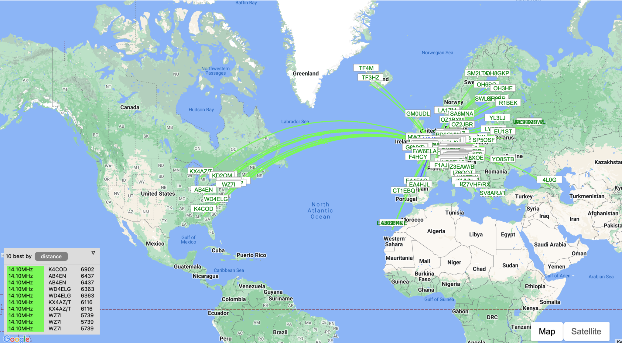
WSPR 20m band reports over the last 24hrs
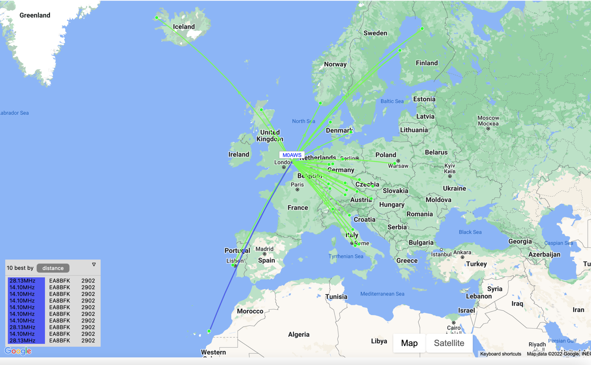
Results on 20m continue to impress with reports from the USA, West Africa coast and as far east as Georgia.
I’ll check the signal on 10m later today using my IC705 to ensure it is transmitting ok and then will leave it running for another 24hrs to see what happens.
UPDATE:
It appears there’s been a reliable opening on both 10m and 20m to the Canary Islands just off the west coast of Africa so far today.
The Weak Signal Propagation Reporting Network (WSPR) known as “Whisper” in the HAM community is a QRP/QRPp beacon mode that is used by many HAMs around the world to see pretty much realtime propagation on the HF bands.
I first started using WSPR when I lived in France some years ago and it proved invaluable for assessing antenna performance and directivity. It’s not a new mode by any means and nowhere near as popular as it used to be as it’s really been superseded by FT4/8 these days that provides the same functionality but, with QSO capability too.
Having an old RaspberryPi hanging around and reading about the WSPR software that’s available for it now I decided to put the Raspi to good use and build a WSPR beacon for the 20m band that I could leave on 24/7.
Having the EFHW Vertical at the end of the garden means that I can connect it directly to the Raspi without the need for an ATU as it’s fully resonant. (It’s actually resonant on 20m and 10m)
I normally run both my RaspberryPi mini computers completely headless and then SSH in to them from my MacBook Pro and decided this was the best way to go with the WSPR beacon too since the WSPR software is command line based and doesn’t require a GUI.
First thing to do was to upgrade the OS from Debian Buster to Bullseye. It’s been a while since I used the Raspi but, it fired up perfectly and connected to the LAN without issue.
After a little time I had the O/S updated to Bullseye and the Raspi was ready for the software build.
The WSPR program comes in source code only so, this means you have to compile it yourself. This isn’t a big job as it comes complete with a makefile.
Using a terminal run the following commands to download and compile the WSPR source code.
So first thing to do is install git.
sudo apt-get install git
Once git is installed I downloaded the software from the git repository.
It only takes a few seconds to download the software which is stored in a new directory called “WsprryPi”.
Before the code can be compiled there’s a small issue with the includes in one of the source code files that needs to be resolved so that the code compiles without error.
cd WsprryPi
vi mailbox.c
Using your favourite command line editor, ‘vi‘ in my case I added the following line into the include statement at the top of the code.
#include <sys/sysmacros.h>
Once added the full include statement looked like this:
Once done, I saved the file ready for compilation.
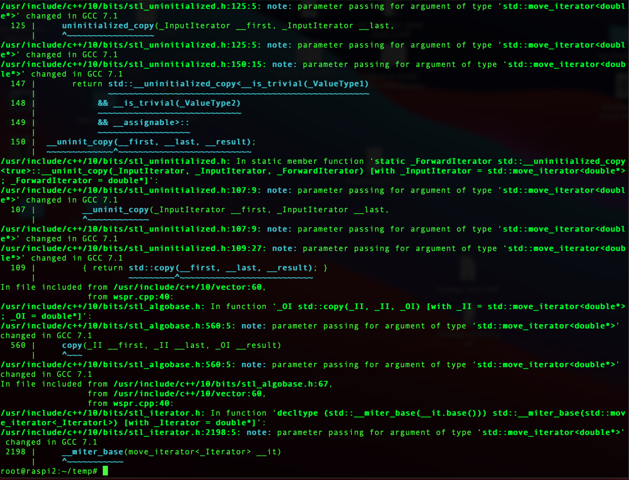
Compiling the code is easy, just run the make command and sit back and watch all the compiler messages scroll across the screen.
make
Compiling the WSPR source code
Once compiled without errors, I just needed to install the binary.
make install
At this point the software is ready to go.
I quickly soldered up a lead to go from the RaspberryPi GPIO pins to the Coax cable that is connected to the EFHW vertical antenna in the garden and connected it all up ready to test.
RaspberryPi 2 WSPR Beacon connected to EFHW vertical for 20m/10m bands
Pins 7 and 9 on the Raspberry Pi’s GPIO pins are where the signal is output. Pin 9 is the Ground pin, and pin 7 is the Signal pin. Pin 7 goes to the inner of the coax and pin 9 to the ground side of the coax.
The purple cable is the ethernet cable connecting the Raspi to my local LAN so that I can access it remotely via SSH. I’ve powered the Raspi off of the USB port on the wifi access point in the radio shack which is always on.
Once it’s all connected it’s just a case of starting the WSPR program from the command line as user root.
wspr -s -r M0AWS JO02 10 20m > ./wspr.log &
I run the WSPR program as root user so that it has the correct privileges to access the devices to communicate with the GPIO headers, if you want too start it as your normal user then you’d need to use sudo to gain the root privileges.
The command line options I’ve used are as follows:
-s
Check NTP before every transmission to obtain the PPM error of the crystal
-r
Repeatedly, and in order, transmit on all the specified command line freqs.
M0AWS
My Callsign
JO02
My Locator Square
10
The power being used in dBm
> ./wspr.log &
Redirects all output to wspr.log in the current directory and then puts the program into the background so that it is left running when I log out.
Once the program is started you can monitor progress by using tail on the log file.
tail -f ./wspr.log
The output you will see will be something like this.
Desired center frequency for WSPR transmission: 14.097100 MHz
  Waiting for next WSPR transmission window...
  TX started at: UTC 2022-07-17 16:06:01.015
  TX ended at:   UTC 2022-07-17 16:07:51.638 (110.623 s)
Desired center frequency for WSPR transmission: 14.097100 MHz
  Waiting for next WSPR transmission window...
  TX started at: UTC 2022-07-17 16:08:01.015
  TX ended at:   UTC 2022-07-17 16:09:51.639 (110.624 s)
Desired center frequency for WSPR transmission: 14.097100 MHz
  Waiting for next WSPR transmission window...
  TX started at: UTC 2022-07-17 16:10:01.015
  TX ended at:   UTC 2022-07-17 16:11:51.642 (110.627 s)
Desired center frequency for WSPR transmission: 14.097100 MHz
  Waiting for next WSPR transmission window...
  TX started at: UTC 2022-07-17 16:12:01.015
  TX ended at:   UTC 2022-07-17 16:13:51.639 (110.624 s)
Desired center frequency for WSPR transmission: 14.097100 MHz
  Waiting for next WSPR transmission window...
  TX started at: UTC 2022-07-17 16:14:01.015
  TX ended at:   UTC 2022-07-17 16:15:51.639 (110.624 s)
Desired center frequency for WSPR transmission: 14.097100 MHz
  Waiting for next WSPR transmission window...
  TX started at: UTC 2022-07-17 16:16:01.014
  TX ended at:   UTC 2022-07-17 16:17:51.639 (110.624 s)
Desired center frequency for WSPR transmission: 14.097100 MHz
  Waiting for next WSPR transmission window...
  Obtained new ppm value: 4.09996
  TX started at: UTC 2022-07-17 16:18:01.015
  TX ended at:   UTC 2022-07-17 16:19:51.640 (110.624 s)
Desired center frequency for WSPR transmission: 14.097100 MHz
  Waiting for next WSPR transmission window...
  TX started at: UTC 2022-07-17 16:20:01.014
  TX ended at:   UTC 2022-07-17 16:21:51.638 (110.624 s)
Desired center frequency for WSPR transmission: 14.097100 MHz
  Waiting for next WSPR transmission window...
  TX started at: UTC 2022-07-17 16:22:01.004
  TX ended at:   UTC 2022-07-17 16:23:51.628 (110.624 s)
You can pass multiple bands on the command line if you want to hop around bands.
It’s also recommended that you add a low pass filter between the Raspi and coax connection to help suppress any harmonics that may be generated. You can make one easily enough using just a capacitor or there are a number of prebuilt low pass filters specifically made for the GPIO hat on the Raspi online.
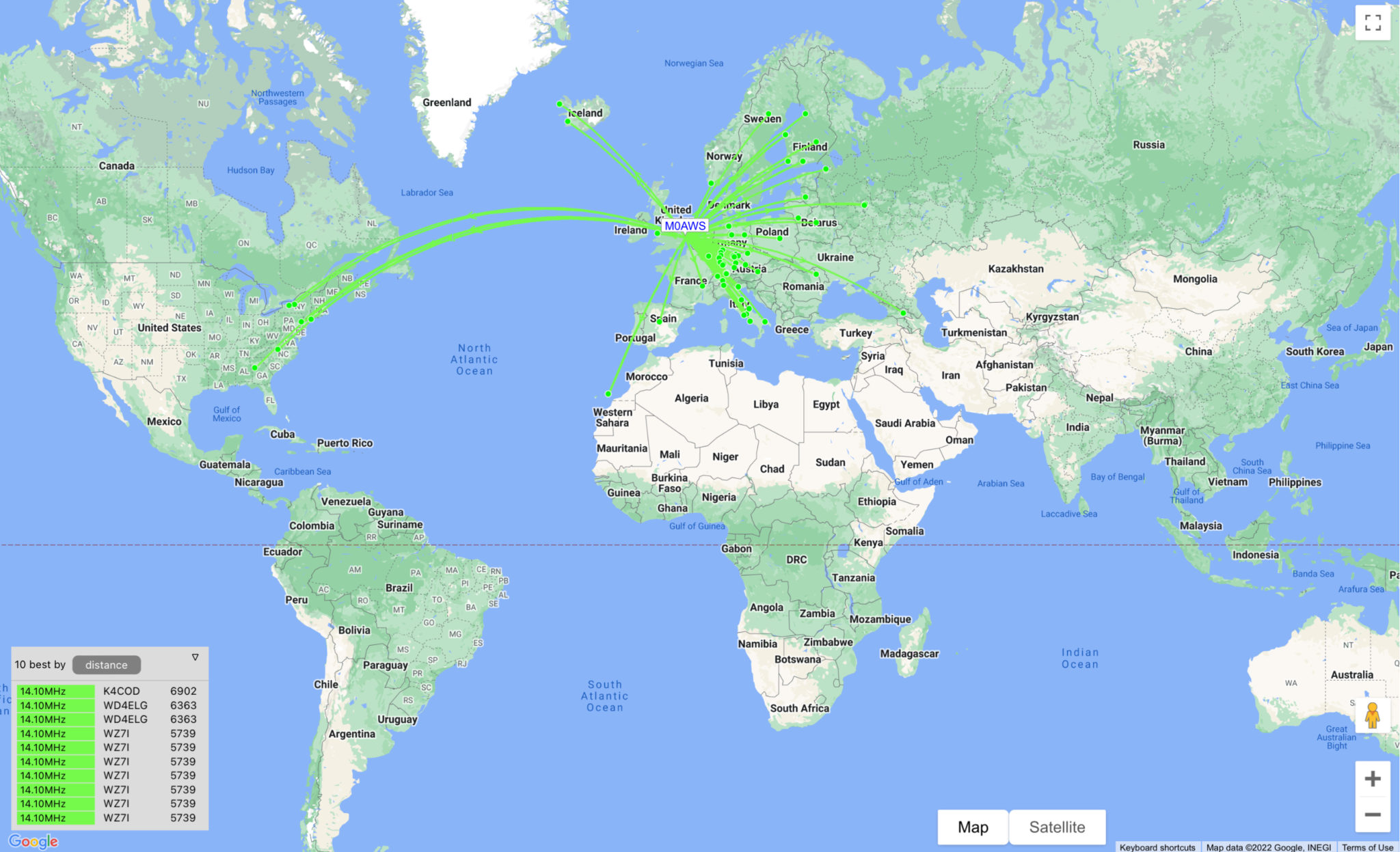
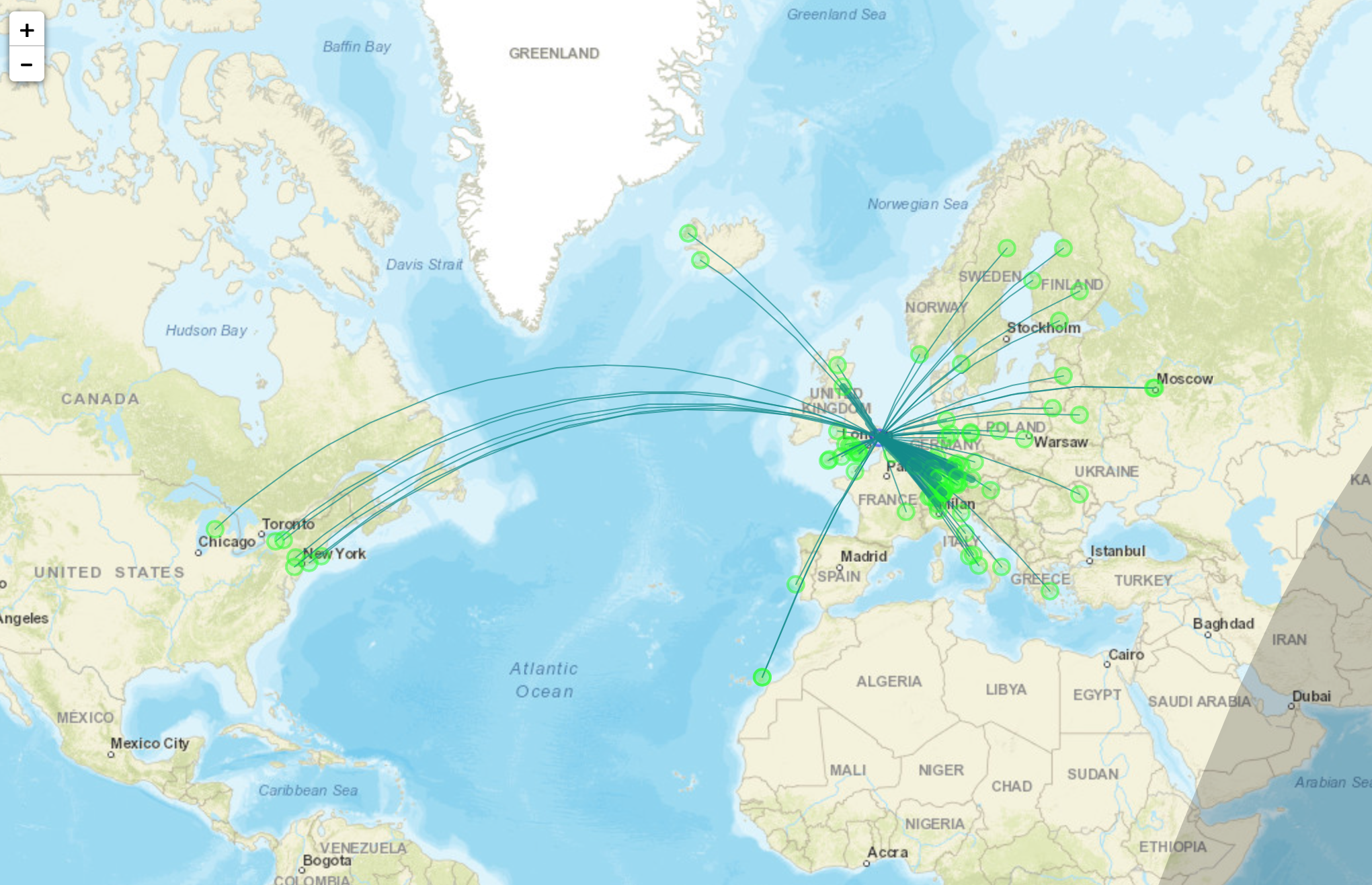
With only 10dBm (10mW) output from the RaspberryPi it’s surprising the distances that the signal travels. In no time at all I had reports from all over Europe and as the day progressed reports started coming in from Iceland, the USA and Russia.
Map showing stations that heard M0AWS on WSPR
I used http://wspr.aprsinfo.com WSPR monitoring website to watch progress as the day went on and after 24hrs had been heard by a number of stations over 3000 miles away.
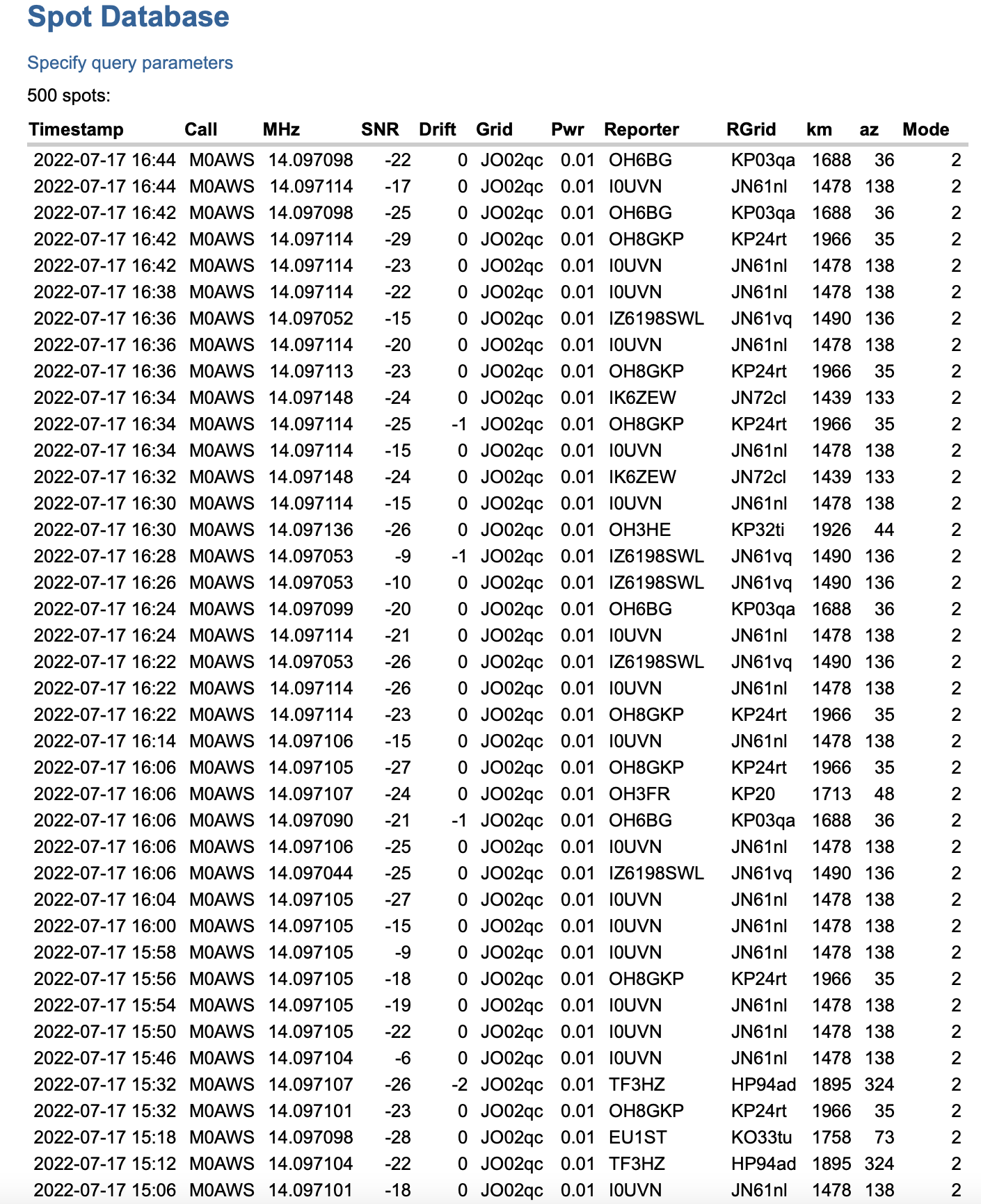
You can also get a more detailed view of reports from the WSPRnet website where you can query the database and create a detailed list of all decodes over a set period of time.
Detailed list of WSPR decodes
Since my EFHW Vertical is resonant on both 20m and 10m I’ll now run it for the next 24hrs on both bands to see what results I get.
Now that I’ve got my new radio shack up and running I decided to give my Icom IC-705 QRP rig an outing and see if I could work a distance of 2000 miles with 1w output.
This is something I’ve been wanting to do for a while but, only being able to sit at the picnic table in the garden or in the summer wasn’t particularly conducive to a long stint on the radio.
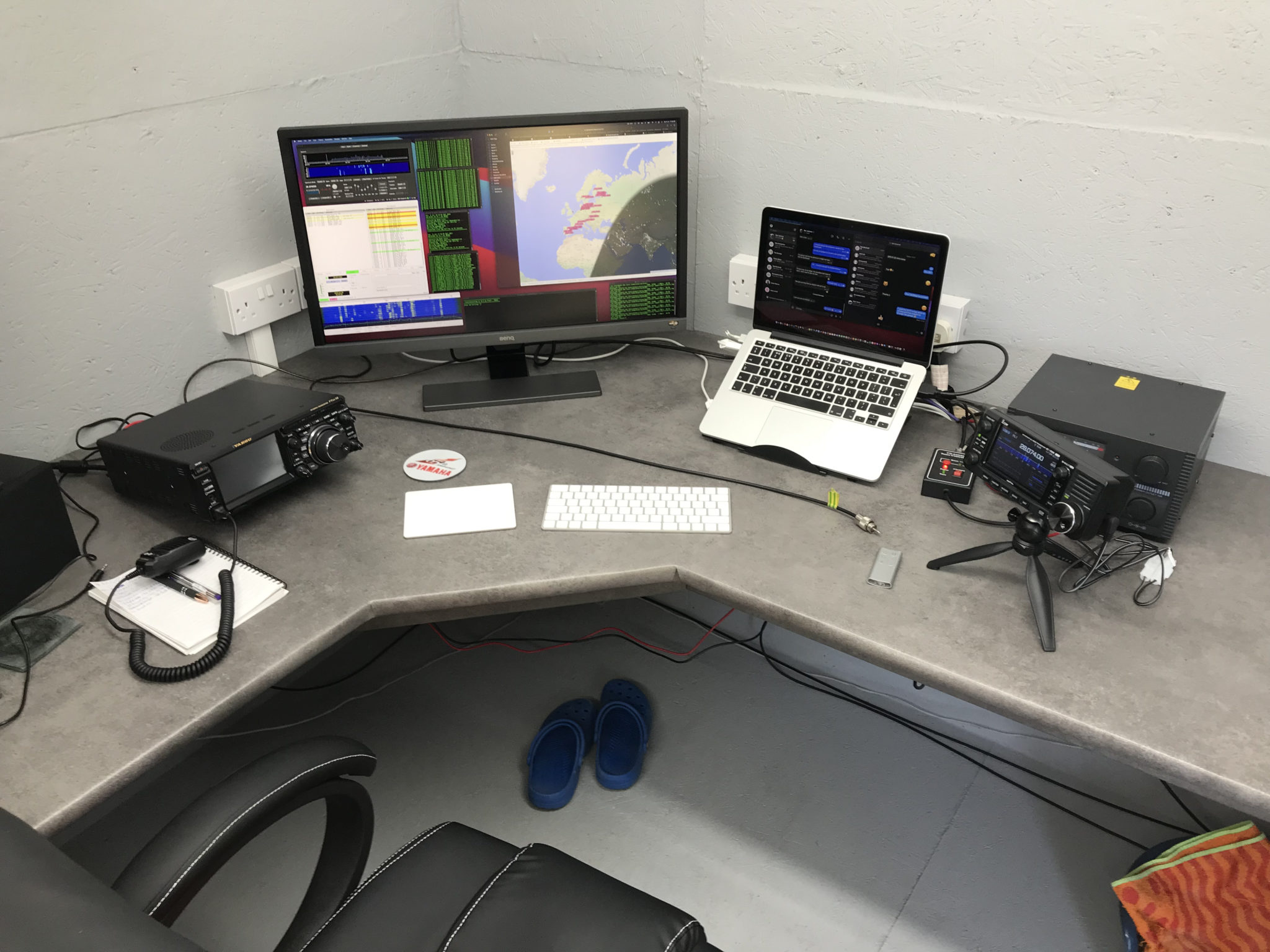
Icom IC-705 wirelessly connected to my MacBook Pro
For this challenge I decided to use FT4 or FT8, whichever was active on the bands. This is a great mode for QRP operations and can get a tiny signal through when other more traditional modes fail.
I used both my EFHW vertical for 20m/10m and my EFHW vertical for 30m that can also be tuned on most of the other HF bands too. This gave me most of the HF bands for the challenge.
Initially I worked a lot of stations in the 600-700 mile range, conditions weren’t brilliant and there was a lot of deep QSB.
My first notable distance QSO was with YO4DG near Mangalia Romania at 1383 miles, this equates to 0.72mW/Mile, my lowest mW/Mile achievement up until this point.
Not long afterwards I saw SV8DCY on the WSJTX waterfall, I wasn’t sure if he’d hear me or not but, I gave a call. To my surprise he came back and became the longest distance QSO for a short time. At 1485 Miles to Kalloni Lesvos Island, Greece this equates to a new low of 0.67mW/Mile.
I then went on to work a bunch of stations in the 1000 miles or less range for a while as conditions on the bands were up and down. It’s amazing how many times I got an answer from a station only for them to disappear completely before the QSO was completed.
The next contact of note was with CU3HN in the Azores, 1713 Miles at 0.58mW/Mile, a new lowest mW/Mile record set. it’s amazing how far you can get a signal with such a tiny amount of power.
RV6F in the Stavropol region of Russia was the next big mile marker, 1932 miles at 0.51mW/Mile. It took a number of attempts to get the QSO to complete as we kept losing each other due to the deep QSB that was between us on the 20m band but, with a little patience and persaverance we eventually got the QSO to complete and it was in the log.
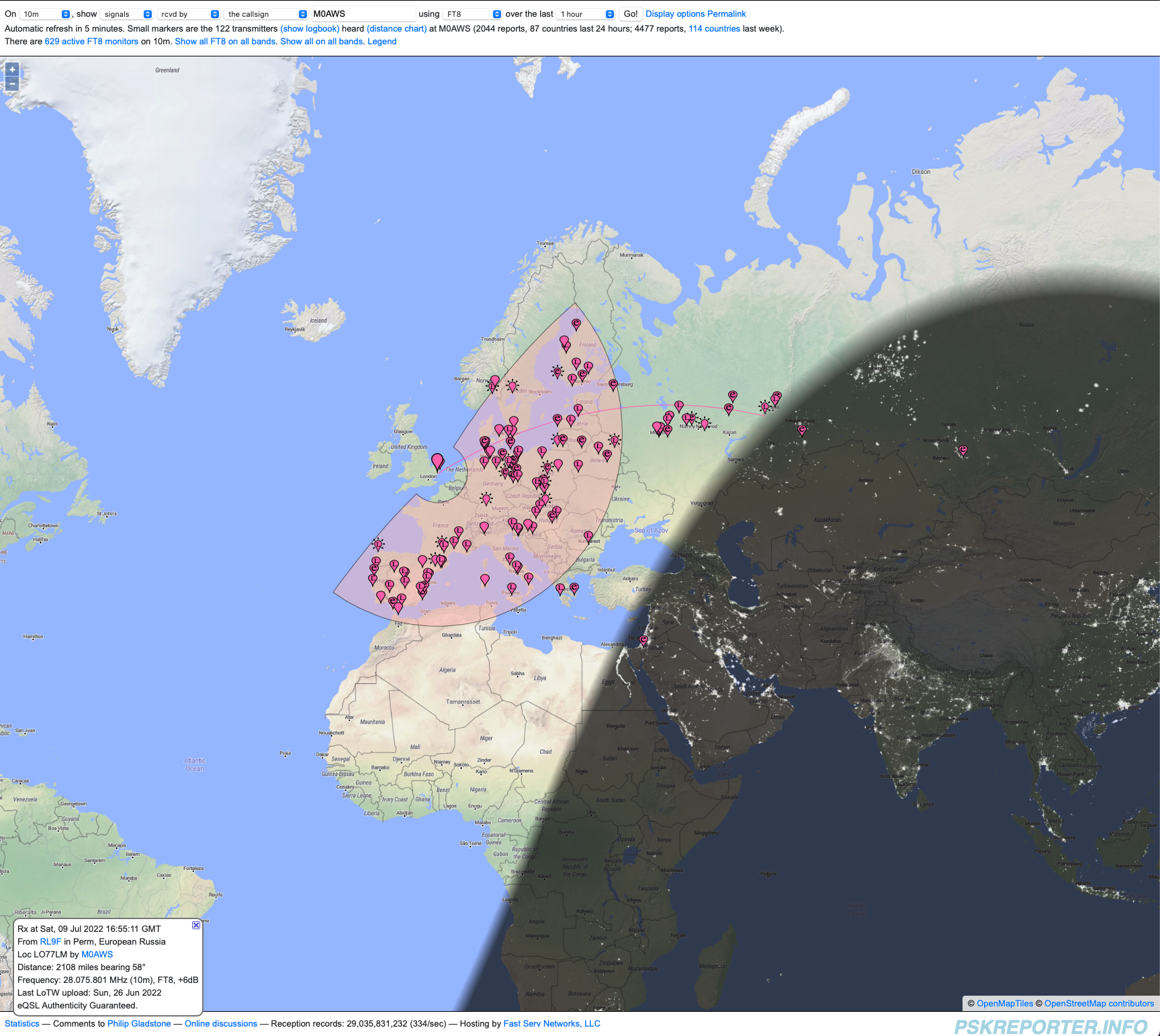
At this point I decided to switch over to the 10m band to see if it had opened up to more than just Europe. When I checked earlier there were only European stations being heard, most being well under 1000 miles. Sure enough the band had indeed opened up and I was hearing stations out to the east that were in excess of 2000 miles.
PSKReporter map showing signals heard on the 10m band
After tuning up and listening for a bit my first call was to RL9F in Perm Russia. This was the one that I’d been looking for, 2084 miles at 0.47mW/Mile this was the one that could complete the challenge.
After a few failed attempts due to deep QSB we eventually got a complete QSO in the log finishing the challenge.
2000 miles using 1w is a lot of fun, frustrating at times when you’re being heard by stations on the east coast USA but, none are answering your reply to their CQ calls.
PSKReporter has proven invaluable, being able to see who can hear you makes a big difference when trying to eek out the last mile when using next to no power.
In total 31 stations were worked over a 9 hour period, not huge numbers but, for many an M0AWS call sign isn’t exotic enough to answer and so many of my calls to stations were ignored. Sad really.
You can view all the log entries for the 2000 Mile 1 Watt challenge on my WSJTX Log.
So, what next? Well I guess it has to be 3000 miles or more using just 1w from my trusty Icom IC-705.
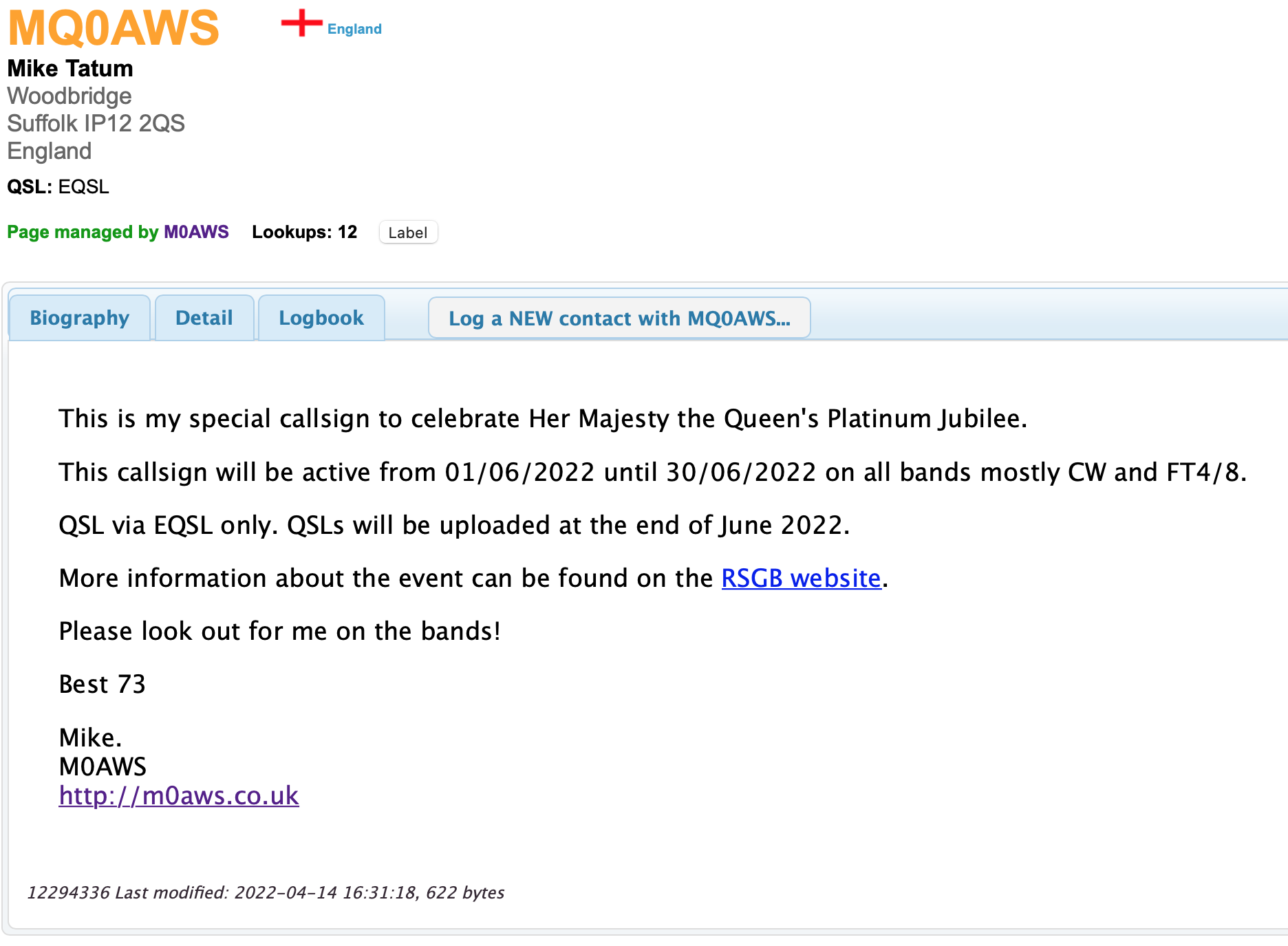
To celebrate Her Majesty the Queen Platinum Jubilee, marking 70 years of service to the people of the United Kingdom, the Realms and the Commonwealth, U.K. Radio Amateur (HAM) operators can apply for a Notice of Variation (NOV) to use the Q Regional Secondary Locator.
The RSGB will also be operating a bunch of GB70 special event stations, full details on the GB70 website.
I have my NOV and will be on air using MQ0AWS for the whole of June 2022.
This callsign will operate for one month only and so will be a rare one for you to get in your log.
I will be operating on all HF bands 160-10m CW & FT4/8 and maybe some SSB depending on conditions.
All MQ0AWS logs will be uploaded to my website almost realtime and will be uploaded to EQSL at the end of June 2022.
Since getting my Icom IC-705 I’ve had a constant issue with interference on the HF bands from the USB connection on the radio when the AH-705 remote auto ATU is connected.
If I use the radio without the AH-705 inline there is no issue at all but, as soon as the AH-705 is connected to the radio there is some 9 S points of computer data noise across all the HF bands rendering them unusable.
Reading online this appears to be a common issue and so I set about trying to find a resolution.
The noise is most likely being induced onto the outer braid of the screen on the cables and so I decided to look into making a common mode choke.
Visiting the HAM Goodies website I ordered a couple of FT240-31 Ferrite Toroids as I’d read this particular mix is ideal for making common mode chokes.
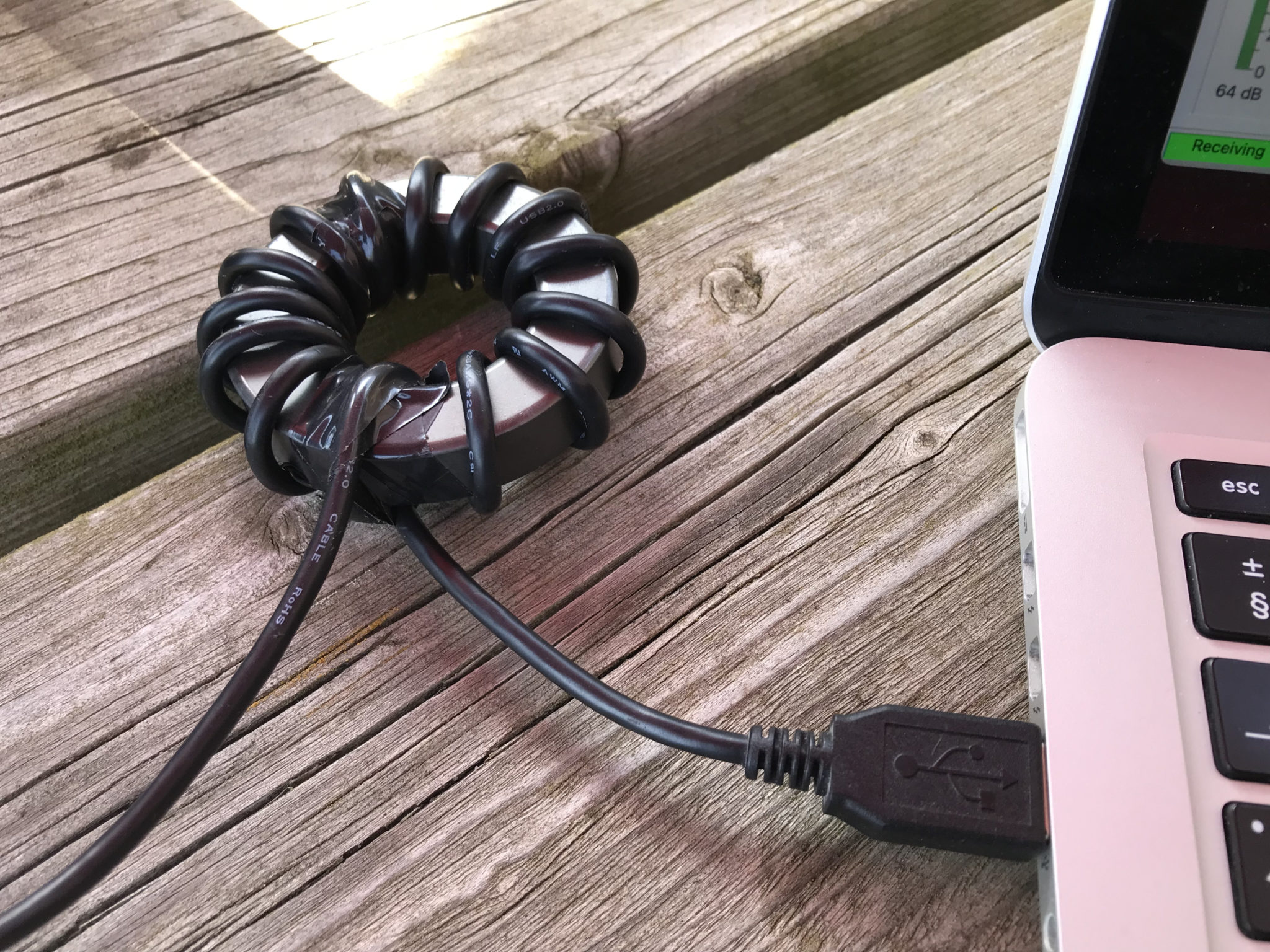
USB Cable wrapped around a FT240-31 Ferrite Toroid to create a choke
I wrapped a long USB cable around the toroid and used some tape to hold the cable in place, it’s surprising how much length is lost by simply wrapping around what looks like a very small toroid.
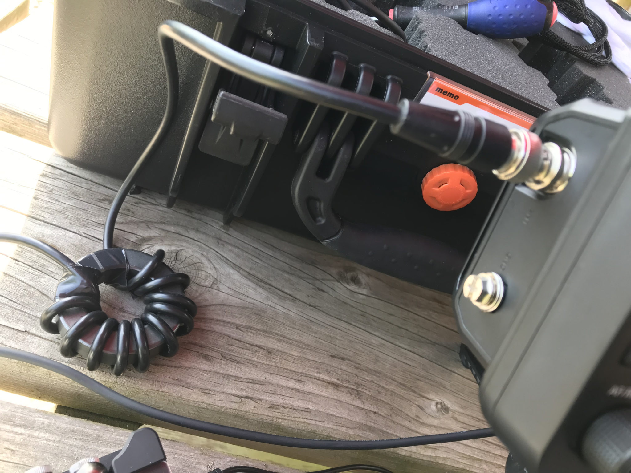
Firing up the radio the noise was reduced considerably but, it was still there and so I decided to do the same to the coaxial cable between the AH-705 and the IC-705.
Coaxial cable between AH-705 and IC-705 wrapped around a FT240-31 Ferrite Toroid
Once I’d wrapped the coax around the toroid and reconnected the coax between the radio and ATU I was pleased to see that the computer data noise was now gone on all bands except for the 10m band. For some reason the 10m band interference is still as strong as it was without the toroids in place.
I’m not too sure why this is. I tried more and less turns on the toroid to no avail and so eventually I decided to just live with it for the time being.
At least now I can use 160m -> 12m without any interference whatsoever, a massive improvement on what I had before.
I need to do some more research on the different mixes of the ferrite toroids and perhaps trying a different mix will resolve the problem on the 10m band too.
I spent some time this morning in the garden with the Icom IC-705/AH-705 combo connected to my End Fed Half Wave (EFHW) vertical for the 30m band. This is a great antenna that works superbly on the 30m band. Being a resonant half wave fed via a 49:1 Unun it doesn’t require any ATU inline normally and so it’s quick and easy to use with any radio.
Today I decided to disconnect and remove the 49:1 Unun and hook up the Icom AH-705 instead. I thought it would be an interesting exercise to see how well it handled the EFHW vertical on both 30m and the other bands.
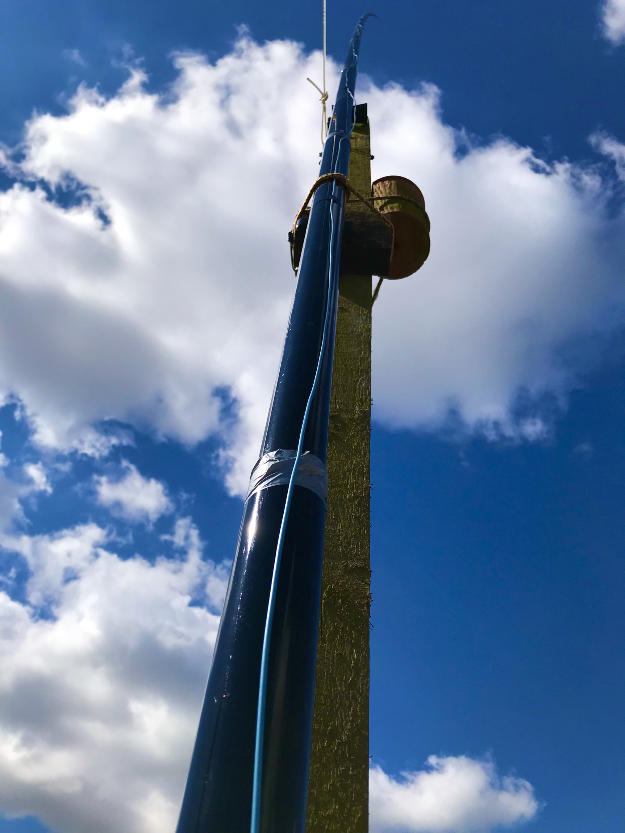
Icom AH-705 connected to the 30m Band EFHW Vertical Antenna
I purchased a couple of 5m leads for the AH-705 so that I could setup the radio on the picnic table in the garden and be a comfortable distance from the antenna. They worked great and allow me to use the radio in the spring/summer sun with ease.
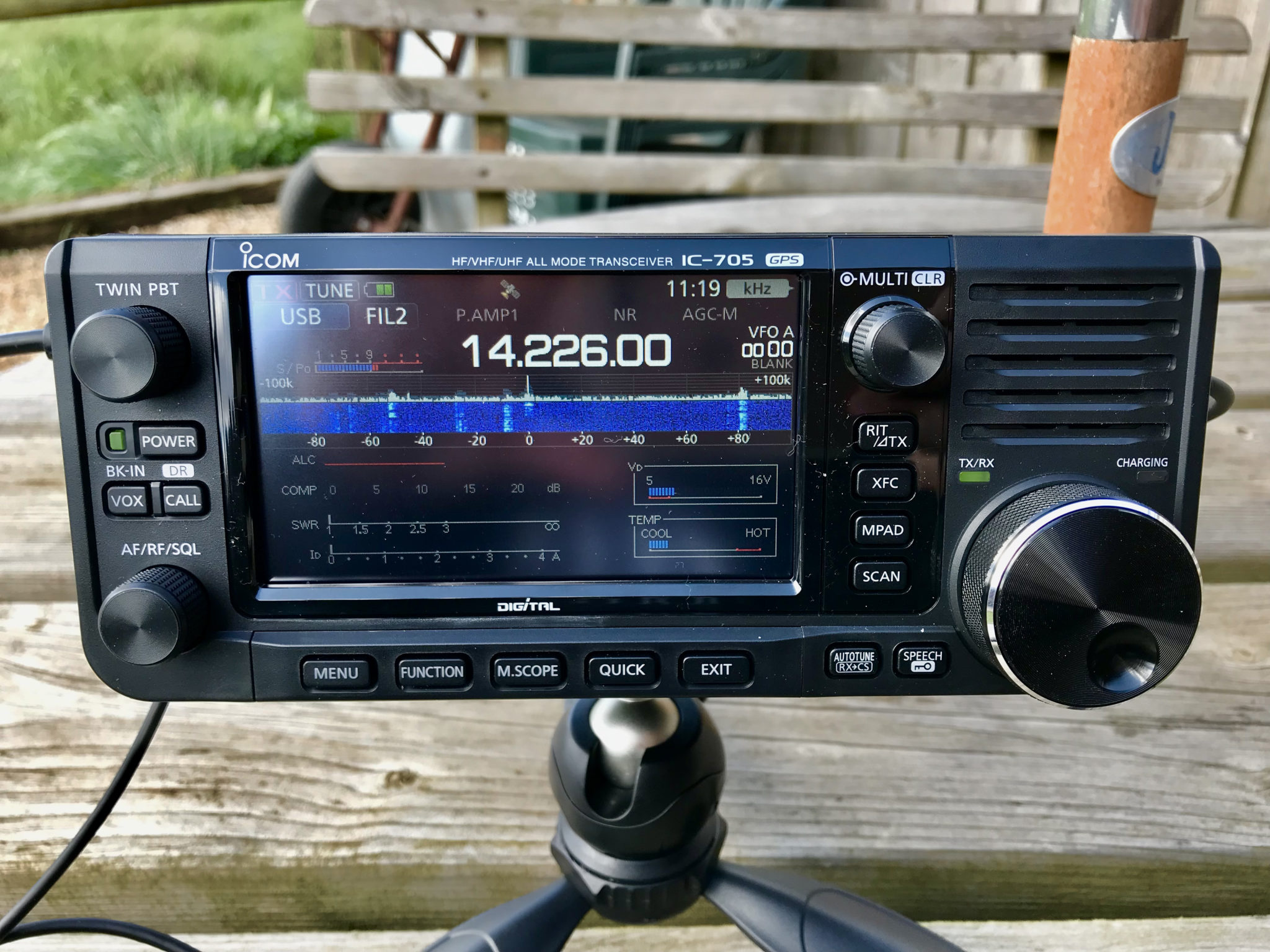
Icom IC-705 setup on the picnic table in the garden
The little AH-705 remote auto ATU really does work well with the IC-705. Each time you change bands all you have to do is give a quick press of the PTT on the mic and it automagically goes into tune mode and matches the antenna to the 50 Ohm radio in seconds.
I was was really pleased to see that the AH-705 ATU matched the EFHW Vertical for 30m on the 80m, 60m, 40m, 30m and 20m bands with a perfect 1:1 SWR. With the antenna consisting of 14.81m of wire this makes it somewhat short of a 1/4 wave on the 80m band and I’m not too sure how well it will work. On the 40m band it is a 3/8 wave antenna so should work well. It’s a 1/4 wave on the 60m band and of course a half wave on 30m band as per it’s original design. On the 20m band it is just under 3/4 wavelength long so hopefully should work reasonably well. Of course it won’t be as good as my 20m band EFHW Vertical that has a much lower angle of radiation but, will make an interesting comparison.
The antenna also tunes up nicely on all the other higher bands including the WARC bands. On 17m it is getting close to a full wave length and on 15m it is just over a full wavelength and so should work fairly well on these two bands albeit with a higher than optimal angle of maximum radiation.
On the 12m band it is 1.25 wavelengths long and of course on the 10m band it is almost 1.5 wavelengths long. I’m not sure how well it is going to work on these two higher bands but, for a 14.81m long piece of wire it certainly gives me a good chance on a wide spectrum of frequencies.
30m Band EFHW Vertical Antenna in the breeze
The bands weren’t in particularly good shape this morning but, I found some SSB signals on the 20m band and so decided to see if I could make some contacts.
First contact was with S51DX in Slovenia. He was using 1kw into a 5 element beam pointed pretty much directly at me. The little IC-705 S meter took a pounding with him peaking +30db over S9 most of the time. I was really pleased to get a 5/9 report from him using just 5w from the IC-705 on the standard 7v battery. Of course his station was doing all the work but, it’s good to take advantage of these big stations when running QRP power levels.
Next I had a QSO with John, EA7JUR in Almeria Spain. But this time the battery on the IC-705 was pretty much exhausted and so I hooked it up to the 12v supply to get it charging whilst I was on air. This of course gave me the ability to increase my O/P power by 100% to a massive 10w!
I wasn’t so strong at John’s end, only getting 5/5 report at best whilst he was 5/5-5/9 with me with some QSB. John was using a mini beam antenna again pointed towards me so once again all the work was being done at his end. We had a good chat for a number of minutes until it was time for lunch.
Listening on the 40m band I did hear a very interesting station, KN6IPA/Aeronautical-Mobile. Justin, KN6IPA is part of the crew on a USAF KC135 air-to-air refuelling tanker that flies out of RAF Lakenheath in the U.K. He was transmitting from the aircraft whilst in flight over Germany. His signal was between 5/9 and 5/9+20dB on my vertical antenna and had a massive pileup of people calling him from all over Europe.
I did try calling him with my punchy 10w of power but, couldn’t compete with the huge pileup of very loud, powerful stations all incessantly calling. It was really interesting to just sit back and listen to Justin’s information. He was using 300w into a wire antenna that runs from the fuselage to the vertical stabiliser. Of course being so high up he had a massive advantage and could be heard for hundreds of miles with ease, hence every one and their dog was calling him.
Photo of the KC135 tanker that KN6IPA was transmitting from courtesy of his QRZ.COM page
If you look closely at the photo above of the KC135 that Justin is a crew member on you can just make out the wire antenna on the vertical stabiliser.
I have to admit that I would love to spend a few hours on the radio aboard the KC135 whilst it was flying around, just imagine the DX you could work!
During the month of June 2022 U.K. radio HAMs will be able to use the “Q” regional secondary locator in their callsigns to celebrate Her Majesty the Queen’s Platinum Jubilee.
I now have my notice of variation (NOV) for my HAM Radio licence that will allow me to use the callsign of MQ0AWS throughout the month of June 2022.
I’ll be active on all HF bands using CW and FT4/8 mostly. I may do some SSB on 40/60m depending on how it goes.
I’m hoping many stations world wide will want to contact the GQ/MQ/2Q stations throughout the celebration period and that you’ll all be able to collect the 70 necessary callsigns and contacts to win an RSGB certificate.
I will be logging all contacts on EQSL.CC at the end of June 2022.
More information is available on the RSGB website.
I look forward to using the MQ callsign and hope to have many pileups on the bands!
I’ve started thinking about antennas for the M0AWS QTH. Unfortunately we only have a typical U.K. sized garden now, which is tiny compared to the acres we had when we lived in France (F5VKM).
So, small gardens means small antennas.
The only direction I can go really is up, although most of my neighbours are very antenna unfriendly!
Like most radio amateurs in the U.K. I’m trying to find a single antenna that will give me the best performance possible on as many bands as possible.
Of course we all know there is no unicorn antenna that does it all but, with some compromise we can do fairly well on a mix of bands with a little consideration.
To this end I’ve been looking at Inverted L antennas. It’s not an antenna I have any real experience of but, it’s interesting to research.
40m End Fed Half Wave Inverted L
I started with a design for the 40m band. A simple end fed half wave inverted L antenna that consists of two parts. The vertical section is 11.95m high and the horizontal section is 8.7m long. Total length of wire is 20.65m. Modelling the antenna with 1.5mm wire it gives some surprising results.
3D Field Plot on 7.1Mhz2D Field Plot on 7.1Mhz
As shown in the two field plots above, the antenna has an extremely low angle of max radiation making it ideal for DXing. Gain at 10 Deg is 3.99dBi, not to be sneezed at. The 3D plot shows the overall radiation pattern to be almost perfectly circular.
On the 20m band the antenna presents a favourable pattern considering it’s a full wave length long.
The angel of radiation is somewhat higher than on 40m but, this is to be expected.
2D Field Plot on 14.1Mhz
On the 20m Band the antenna gives a gain of 7.07dBi at 25 Deg. A higher angle of radiation than on the 40m band but, still very usable. At 5 Deg there is 4.29dBi of gain which makes it ideal for DXing.
3D Field Plot on 14.1Mhz
On the 15m band the pattern isn’t as good as on 40m & 20m however, it would still be usable.
3D Field Plot on 21.1Mhz2D Field Plot on 21.1Mhz
With a gain of 6.04dBi at 25 Deg it should perform very well on the 15m band. At 10 Deg there is a gain of 1.12dBi. The overall pattern is a bit lopsided and it also has more high angle radiation than I really want but, like all multi band antennas there’s always a compromise.
Next I modelled the antenna on the 10m band, the 3D pattern is rather alarming but, it has potential.
3D Field Plot on 28.1Mhz
There’s a lot of high angle on the 10m band and a somewhat out of balance pattern but, there’s also gain to be had at a lower angle too.
2D Field Plot on 28.1Mhz
The main gain is 6.37dBi at 45 Deg, ideal for short hop communications however, there is 3.58dBi of gain to be had at 10 Deg, much better for DXing.
It’s not ideal for 10m by any means but, when you take into account that the antenna is 2 wave lengths long it’s hardly surprising.
I’ve still got a lot more work to do on this modelling but, it has huge potential.
I’ve not even started thinking about impedance matching yet, I know it’s going to be a monster and nowhere near 50 Ohms but, I’m sure a simple LC network will do magic with matching it to the transceiver.
More soon …
We use cookies to ensure that we give you the best experience on our website. If you continue to use this site we will assume that you are happy with it.