Will raising my vertical antenna make it work better?

A question I get asked regularly is:

“Why don’t you mount your 20m EFHW Vertical antenna higher up in the air?
It’ll work much better the higher you get it”.

I have over the years tried raising and lowering my vertical antennas for DXing and found that keeping the base of the antenna and feed point low has advantages over a raised installation. I’ll try and explain this using some 3D and 2D far field plots from the EzNEC antenna modelling software that I use.

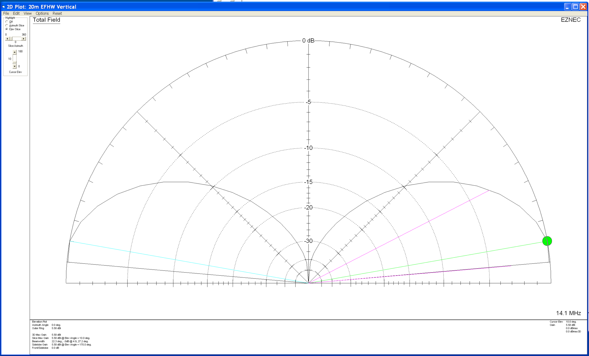
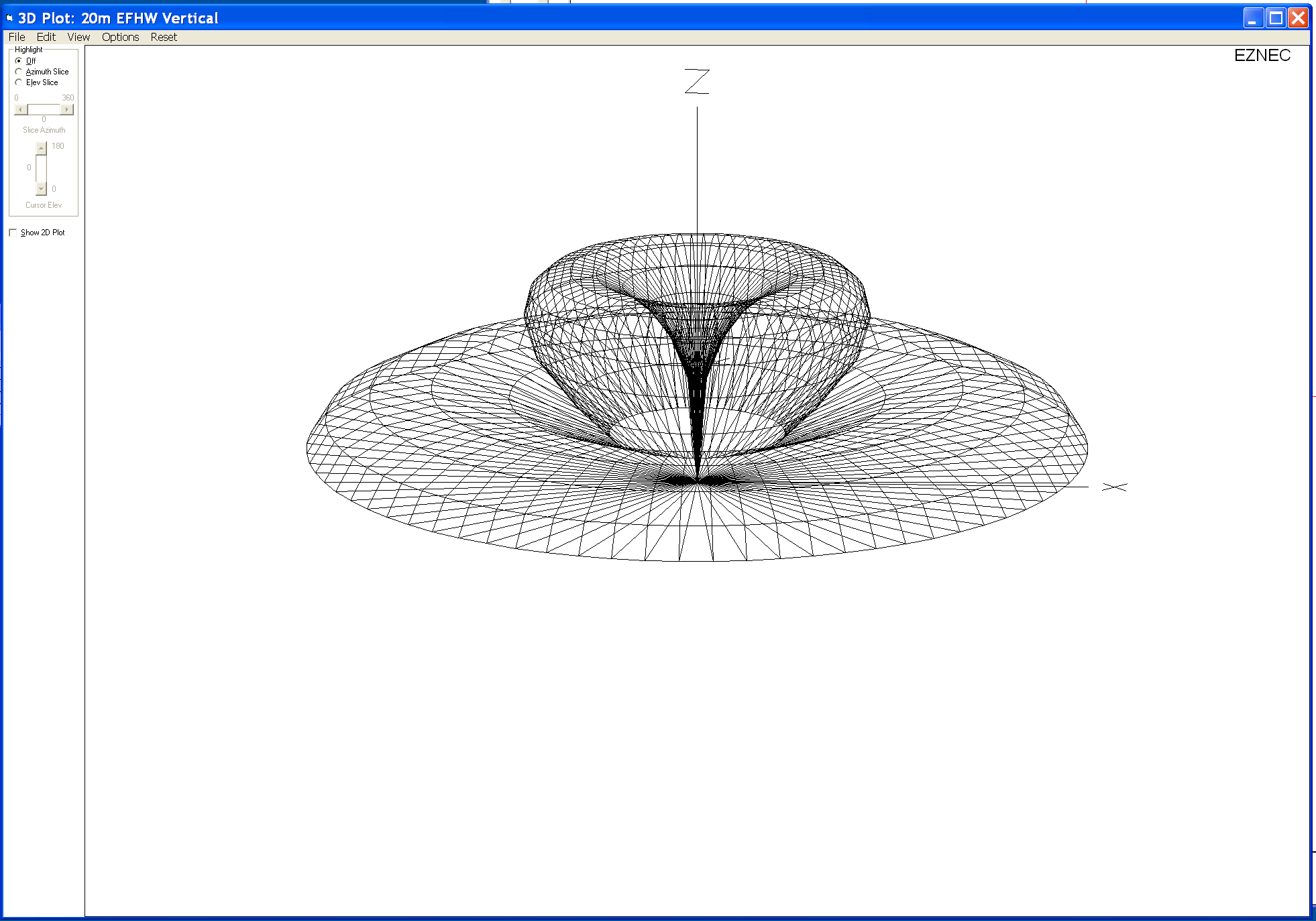
Below are the 3D and 2D far field plots as I have it setup at the moment. The 49:1 Unun is at ground level with the base of the antenna also at ground level.
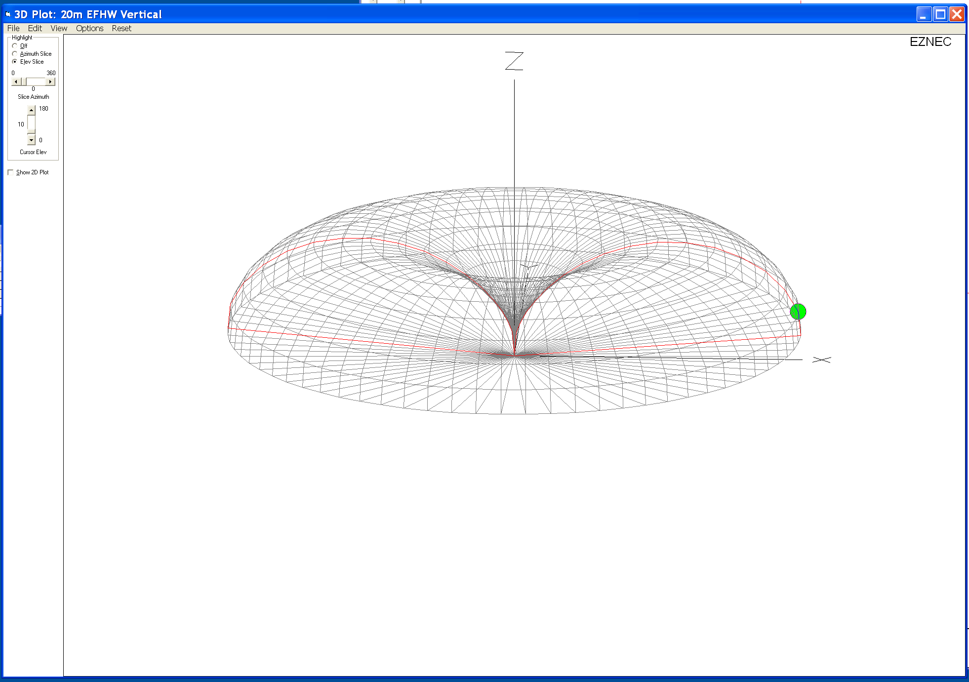
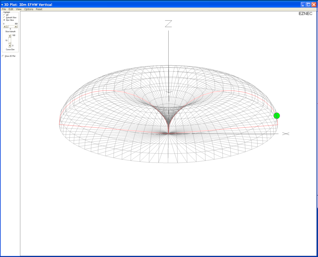
20m EFHW vertical fed at ground level 3D Plot
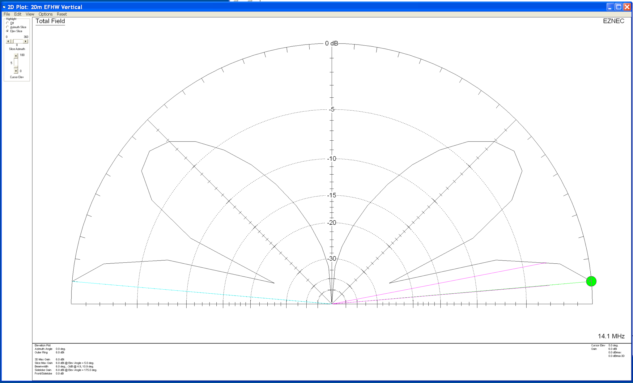
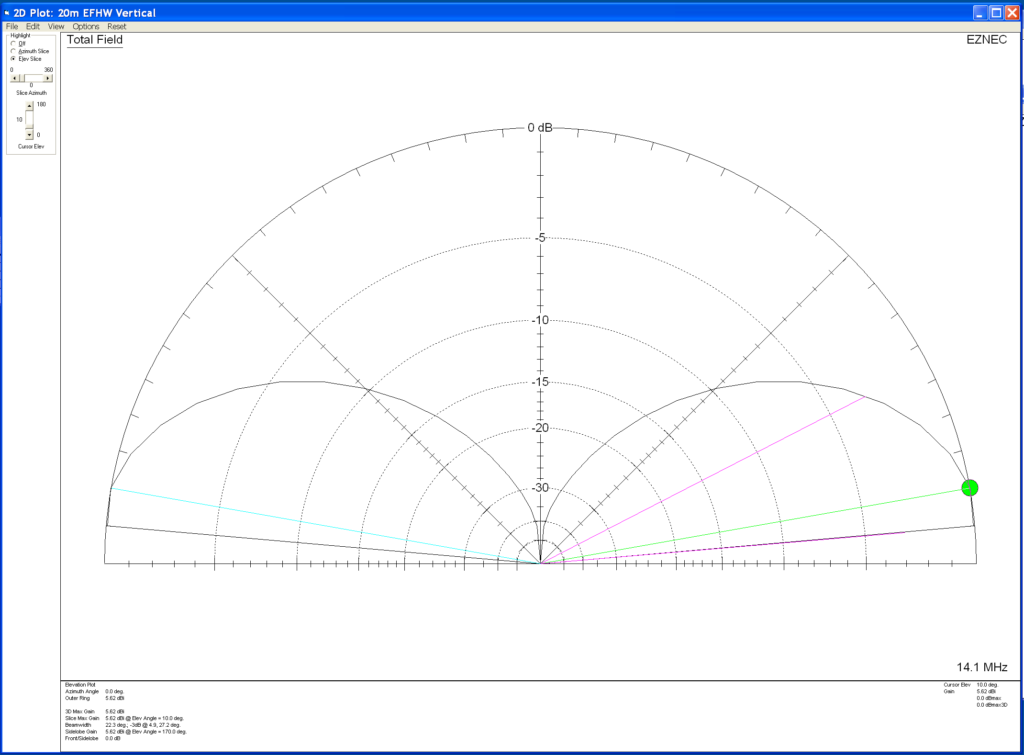
20m EFHW vertical fed at ground level 2D Plot

Forgetting about the dBi gain figures for the time being and just concentrating on the overall radiation pattern you can see that with the antenna fed at ground level it has a typical circular radiation pattern with a deep null in the centre and a very low angle of maximum radiation. This makes the antenna perfect for DXing and is backed up by the success I’ve had on the 20m band working Australia, Thailand, Indonesia, South America, West Coast USA and Canada. This is exactly what I wanted and I’m extremely happy with it’s performance. I must add that I’m not looking to work European stations with this antenna, I’m only looking for DX stations especially those with very weak signals.

So now let’s take a look at what happens to the radiation pattern when we raise the antenna and the feed point above ground level.

First let’s raise the antenna so that the base and feed point are 3m above ground level.

20m EFHW Vertical with base and feed point 3m above ground 3D Far Field Plot
20m EFHW Vertical with base and feed point 3m above ground 2D Far Field Plot

Looking at the two far field plots above you can see that with the antenna and feed point raised by 3m we start to get some high angle lobes appearing in the centre of the radiation pattern. The overall maximum radiation is still at a low angle and so this would still be good for DXing but, does have an element of high angle radiation to it now. This will of course mean we’ll start to be able to work stations much closer to us and also be able to hear them better.

Raising the base of the antenna and feed point to 5m above the ground we see that the high angle lobes get even bigger and start to distort the overall radiation pattern of the antenna.
20m EFHW Vertical with base and feed point 5m above ground 3D Far Field Plot
20m EFHW Vertical with base and feed point 5m above ground 2D Far Field Plot

At 5m above ground the two high angle lobes have increased considerably which will result in more high angle radiation from the antenna. Maximum radiation is still at a low level though and so DXing will still be good with this setup but, from experimentation and experience I know that there are times when closer stations start to affect the ability to pick out the weaker DX stations. This is exactly what I don’t want.

Raising the antenna up even further to 10m above ground we get the following result.

20m EFHW Vertical with base and feed point 10m above ground 3D Far Field Plot
20m EFHW Vertical with base and feed point 10m above ground 2D Far Field Plot

At 10m above the ground the two high angle lobes shown on the 2D elevation far field plot are now almost as big as the main lobe below it. This means there will be considerable high angle radiation from the antenna which will result in the ability to communicate with stations much closer to your QTH rather than focusing just on the DX stations.

If you’re looking for the best of both worlds then getting your antenna up higher is the way to go, you’ll be able to work stations in the 300-1500 miles range with ease and the DX stations thousands of miles away.

From my experience there is one disadvantage with this in that the closer stations tend to drown out the weaker DX stations reducing the overall DX capability of the antenna and this is why I keep the antenna feed point at ground level. From experimentation and experience gained over the years I’ve found that keeping the antenna base and feed point at ground level gives me a better chance at working the DX than I have if I raise the antenna up higher.

As with everything in life there’s always a compromise!

So it really does depend what you want to use your antenna for. If like me you only want to chase those rare DX stations that are always difficult to get then keep the base of the antenna and feed point low. This will maximise the null in the centre of the radiation pattern and keep interference from “local” stations to a minimum. The draw back to this of course is that you won’t be able to work the closer stations when there is no DX around.

However, if you want the ability to work more “local” stations and the stronger DX stations raise your antenna and feed point up to a more suitable level above ground so that you obtain more high angle radiation from your vertical antenna. Then when there’s no DX around you’ll still be able to chat with the more local stations.

I hope this helps all the people that read my blog understand the choice I have made and why I keep the base of the antenna and feed point at ground level.

More soon …
Falklands Calling …

When I lived in France (F5VKM) I was totally focused on the low bands. I spent years trying to get the Falkland Islands on 160m. Now living in the UK with a typical small garden I no longer have the luxury of big antennas. Currently I’ve just got my EFHW Vertical for 20m at the end of the garden.

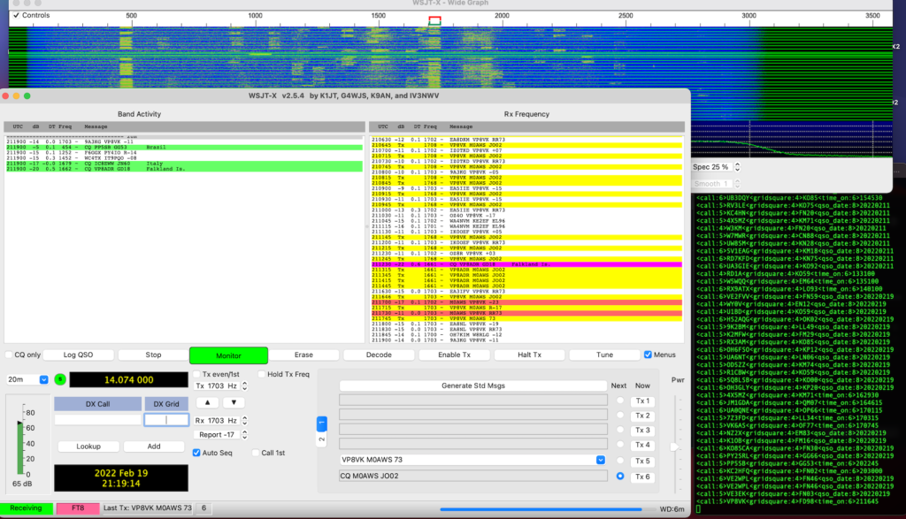
Today I heard the Falkland Islands on 20m for the first time since setting up the new station, I was amazed to say the least.

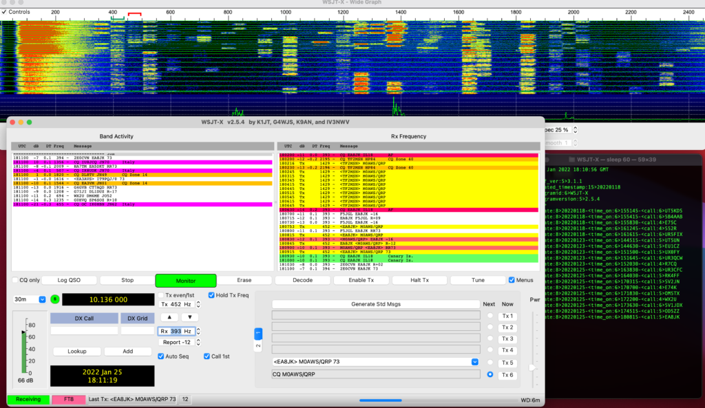
WSJT-X FT8 working VP8VK with just 25w

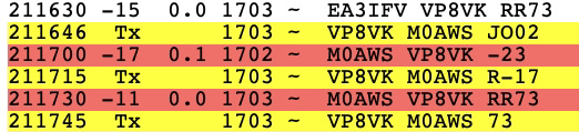
I decided to give the two stations a call, didn’t get an answer from VP8ADR but, VP8VK then popped up and I snuck in and got a quick QSO with just 25w.

FT8 QSO with VP8VK

Working DX is so much easier on 20m than it is on 160m, I’m amazed!

-23dB is very close to the limit for FT8 but, it was enough to get a complete QSO and the Falklands in the log.

I also got VK6AS on 20m FT8 today, again with just 25w. This EFHW Vertical for 20m really is an excellent DX antenna, it’s perfect for the small garden too!

All stations heard FT8 20m

More soon …

Simple EFHW vertical on 20m works great!

I completed the fine tuning of the 20m EFHW Vertical today, I got the SWR down to 1:1 at 14.10 Mhz. This gives me a perfect match for the CW and digital section of the band with the SSB part of the band not exceeding 1.4:1 at 14.350.

I ended up removing 34.5cm of wire from the original antenna length to get the resonance where I wanted it. This was caused mainly by the extra inductance added into the circuit by the 49:1 Unun. This is to be expected and perfectly normal when feeding an antenna via an impedance matching transformer.

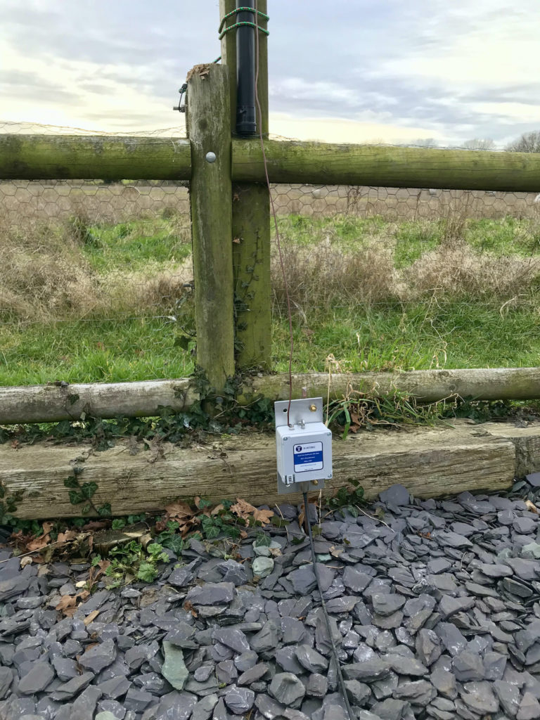
I bolted the 49:1 Unun directly to the earth rod, this way it’s got a solid earth connected directly to it to keep the resistance to a minimum. (The metal mounting plate is also the earth termination point).

49:1 Unun mounted on earth rod directly

I spent some time today chasing the DX on the 20m band using the FT8 digital mode.

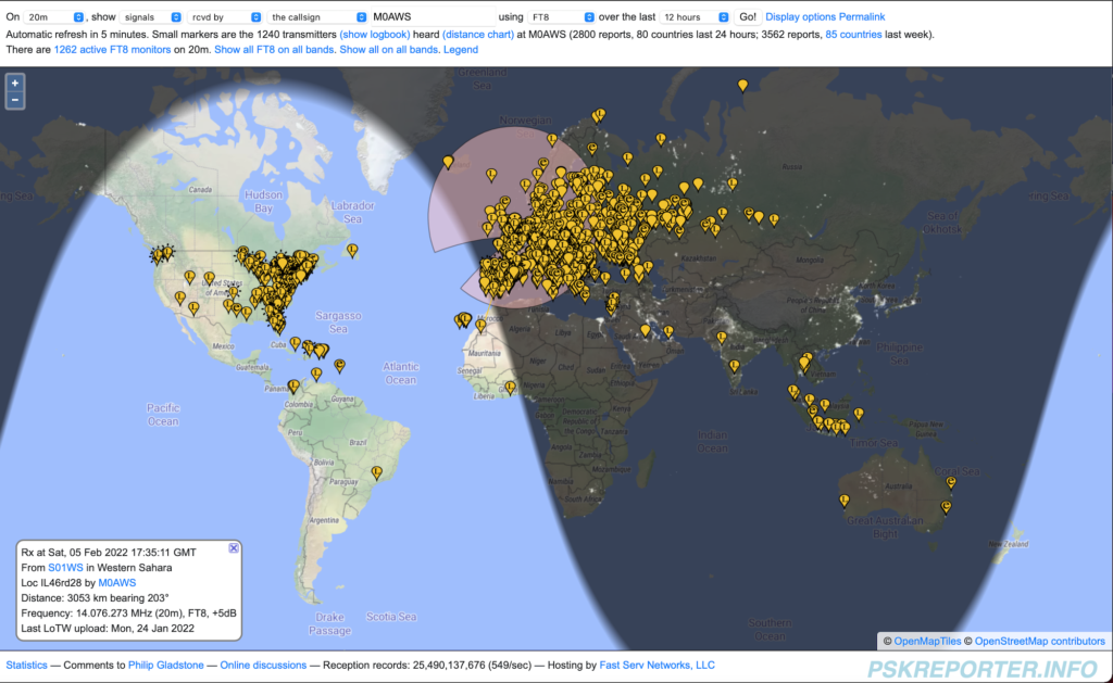
The fun started with VK2LAW in Sydney Australia, followed by E25ETT in Thailand, KP4CAR in Puerto Rico, 9G5AR in Accra Ghana and The Sahrawi Amateur Radio Club station S01WS in Western Sahara. A nice mix of stations dotted around the world.

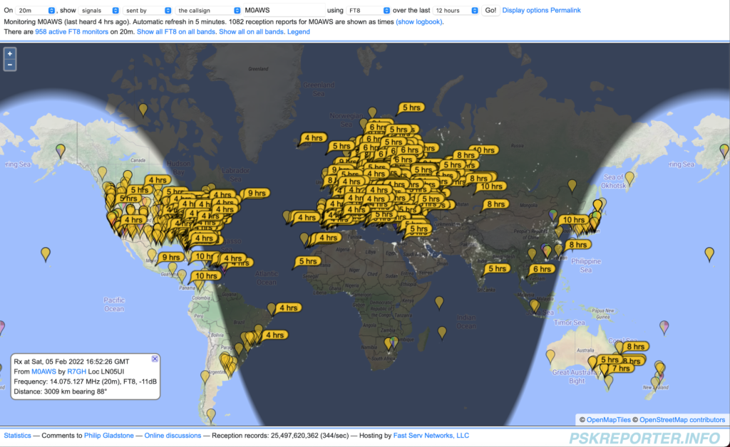
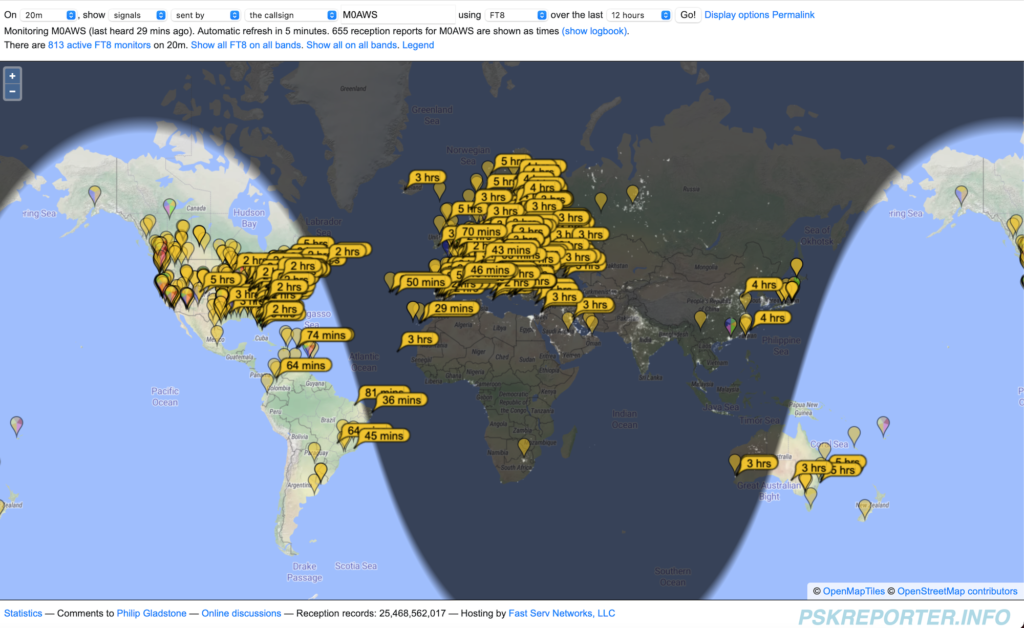
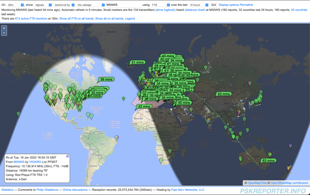
PSKReporter map showing all the stations that I heard on 20m today

I like to keep an eye on the PSKReporter site whilst on air to see what I’m hearing. As you can see I heard stations from the West Coast USA right across to New South Wales in Australia and down south as far as Brazil. The 20m EFHW Vertical antenna and Yaesu FTDX10 radio combination really does have good ears

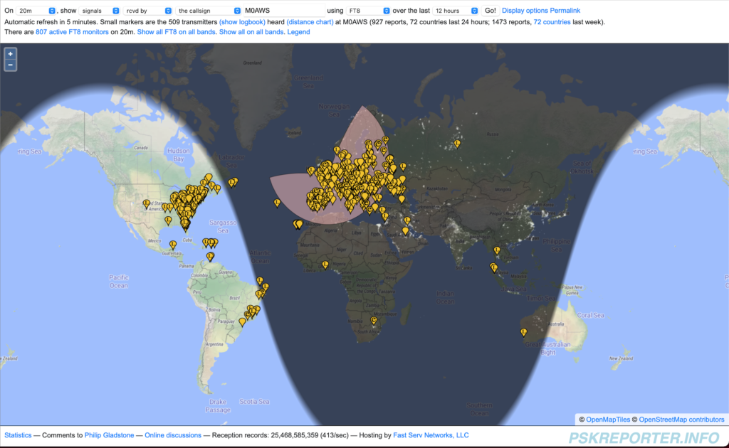
As for being heard, well it’s a similar story, below is a map showing all the stations that heard me as reported on the PSKReporter website.

Stations that heard M0AWS on 20m FT8

One again, great global coverage from the antenna and transceiver combo with only 20w being used for most contacts. (25w used to break some of the pileups!)

Overall I’m really pleased with the performance of the antenna, for such a simple design it works exceedingly well. One huge advantage of a half wave over a quarter wave antenna is that the point of max current is 50% along the antenna’s length, on the 20m band EFHW Vertical this puts it some 5m above the ground lowering the angle of take off and making it a great DX antenna.

If you’ve not got a lot of space but, want to work the DX on 20m then I highly recommend you give one a try, I’m sure you’ll be amazed at how well it performs.

Can’t wait to get a 40m EFHW Inverted L up next!

Information as to why it’s best to keep the feed point at ground level for this antenna is here.

More soon …

20m EFHW Vertical + 49:1 Unun = DX

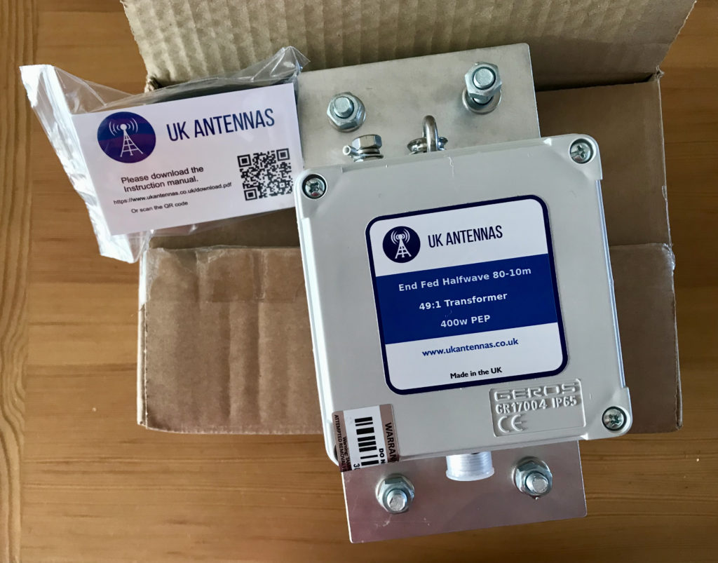
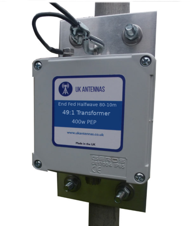
My 49:1 Unun arrived from UK Antennas today, lost no time getting it into the garden and connected to the 20m EFHW Vertical antenna.

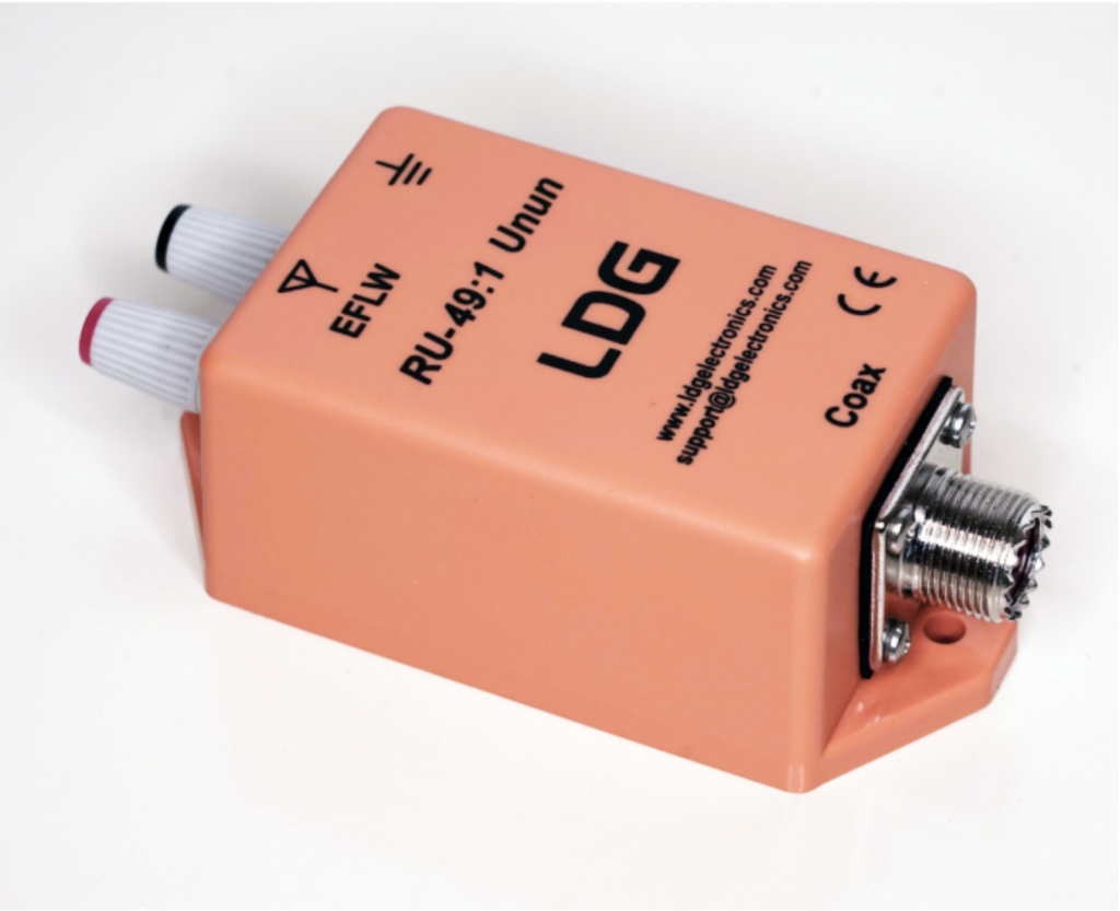
49:1 Unun from UK Antennas

I’m really pleased with the 49:1 Unun, really nicely put together and packaged professionally, great to get such a nice British made product!

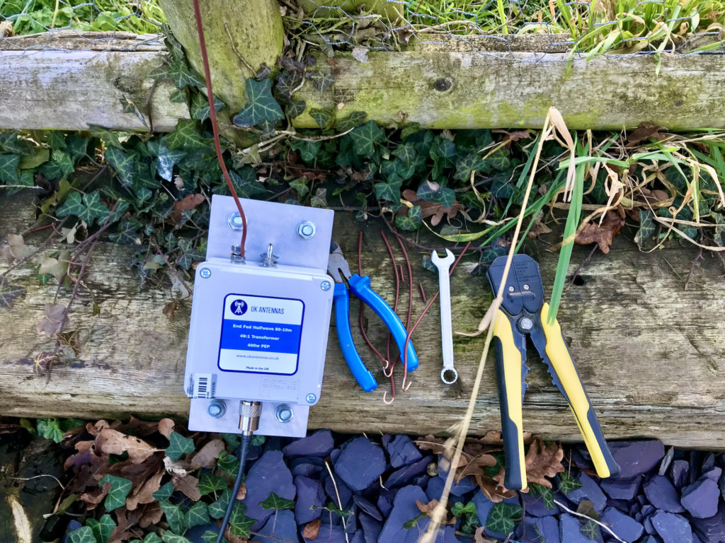
Connecting the Unun up to the antenna I found that it added a little extra inductance I hadn’t planned for and so I needed to shorten the vertical wire a little to compensate.

Tuning the 20m EFHW Vertical

It took 3 snips of wire to get the antenna resonant in the 20m band again, with an SWR of 1.3:1 and the sun starting to set I decided that was fine for now and I’ll fine tune it tomorrow in the daylight. (See end of article for update)

Heading into the shack the 20m band was buzzing, lots of big signals and DX. I switched on to the 10m band and checked the SWR there, 1:1 across most of the band, perfect!

I then went on to check the 15m band, now I wasn’t expecting a match as it shouldn’t resonate there but, I found a 2:1 SWR across the band, weird!

So back on 20m, I plugged in the MacBook Pro and started WSJT-X in FT8 mode to see what was around.

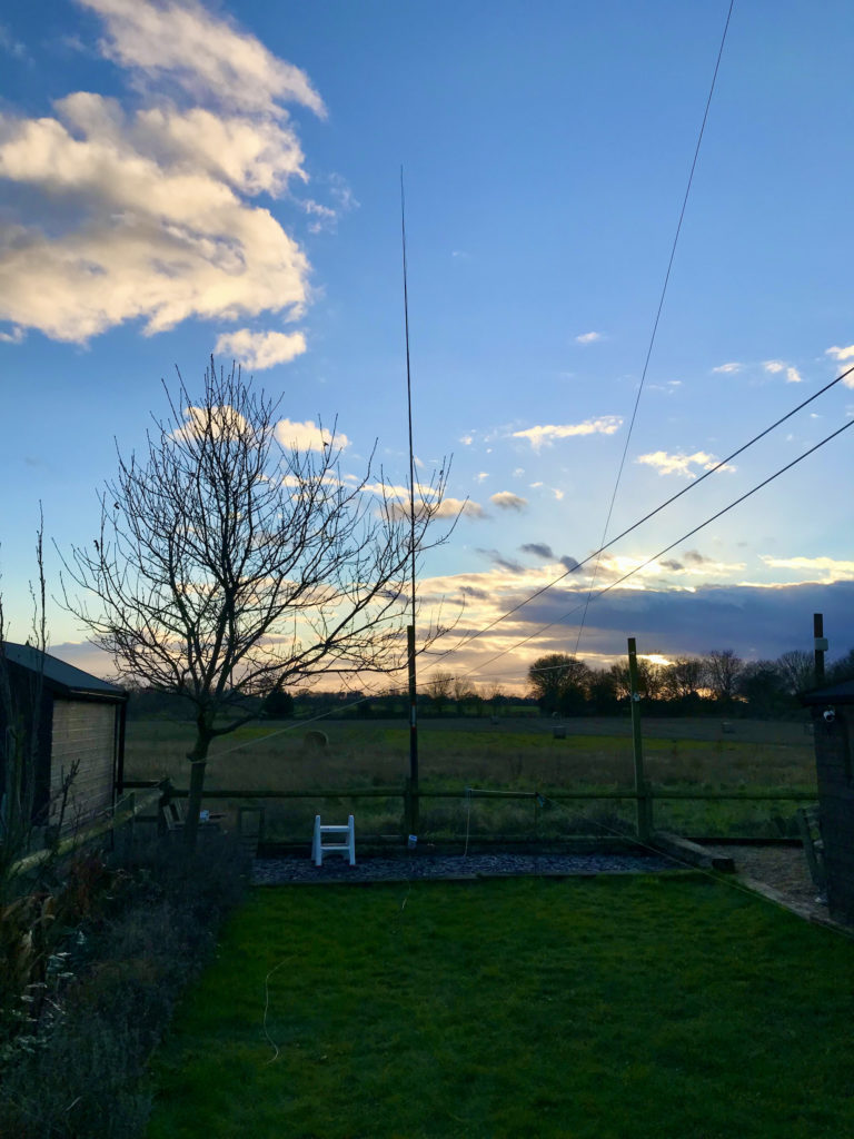
20m EFHW Vertical at the end of the garden

First contact was into Canada, VE2FVV with a -10 report both ways and 2962 miles, not bad for 20w.

I then worked a flurry of stations from the USA but, the one I was really pleased with was PP1WW in Brazil. 5610 Miles using just 20w, this EFHW vertical really does has a lovely low angle of radiation.

PP1WW was the last station worked as it was dark by this time and the band closed. It was interesting to watch the PSKReporter site to see where I was being heard.

Stations that heard M0AWs on 20m

As you can see from the PSKReporter screenshot above, I was heard pretty much all over the world. I saw a number of VK stations in Australia pop up on FT8 but, never managed to get an answer back from any of them even though they reported hearing me on the PSKReporter site.

I was also pleased with the number of stations that I heard, once again good global coverage.

Stations heard by M0AWS on 20m

Band conditions are generally poor at the moment and we’re in a bad part of the 11 year sunspot cycle. Hopefully in the coming years propagation will improve and we’ll be able to work the world on just a couple of milliwatts!

I also tuned up onto the 10m band and heard quite a few FT8 stations on there, I was surprised as I wasn’t expecting the band to be open.

So tomorrow, I need to fine tune the antenna for the 20m band and get the SWR down to 1:1, hopefully this won’t affect the 10m band tuning too much.

Once the 12m Spiderpoles are back in stock I’ll get one ordered and build the 40m EFHW Inverted L that I’ve designed, I’m hoping it will open up the 40m/20/15/10m bands for some DXing over the summer months.

UPDATE: I ended up snipping off a total of 34.5cm of wire to get the SWR 1:1 at 14.100Mhz. This makes the entire 20m band useable with the SWR less than 1.5:1 at each end of the band. 2nd contact after trimming the wire was VK2LAW at 10454 Miles using just 25w of power.

Information as to why it’s best to keep the feed point at ground level for this antenna is here.

More soon …

Free Great Circle Azimuthal Map

I don’t know about you but, when I’m in the garden erecting antennas I find it hard to work out which way I need to orient the antennas to get the DX I want to work. This is especially true with Delta Loop directional antennas.

I remembered that when I lived in France I had a lovely Great Circle Azimuthal Map on the wall in the radio shack showing the world as viewed from space directly above my QTH in Brittany, this would be ideal for my U.K. QTH too.

Hunting on the internet I soon found the site where I got it from, N6NT has a wonderful little website full of handy little widgets, one of which is the Great Circle Azimuthal Map Generator.

M0AWS Great Circle Map

The map is generated in PDF format and can be downloaded and printed locally.

I hope this snippet of info will be of use to some of my readers, it’s certainly very handy for me!

More soon …

Going up in Frequency!

Ever since I got my Class A HAM Radio licence I’ve always been fascinated by the low bands.

160m, 80m and 40m have been my favourite go to bands for chasing DX for many years and I’ve really enjoyed overcoming the challenges that come with such low frequency radio operations. Working DX on 160m I learnt a lot, having a good receiver and a quiet antenna are far more important than having a lot of power. The QRM/QRN on top band often masks the weak DX signals and so designing and building antennas that have a relatively low angle of radiation but, are super quiet on receive is a skill that all top band DXers should embrace.

It’s particularly hard to work DX on 160m in the summer months however, all those DX signals are still there, they’re just masked by the static crashes that plague top band throughout the warmer months.

Discovering the grey line was a real eye opener too. Getting up early in the morning to catch that magic moment that starts just before the sun rises to about an hour afterwards, with DX signals pouring in from VK/ZL before the D layer gets established again. Discovering that on the grey line signals from afar often arrive from a very high angle and can be heard much better on a large horizontal loop near the ground than a large vertical.

As you can tell, I’m passionate about the low bands but, now I’m back in the U.K. and have a U.K. sized garden again those days of large full wave antennas on the low bands are gone and so I must look to pastures new.

To this end I’m going to get onto the higher frequency bands, 20m and upwards. I must admit that I’ve hardly used these bands as I’ve always been so focused on the lower bands.

Currently I have delta loop for 30m up in the garden, this is a great band for us CW and digital guys, it’s a band I really enjoy and so will continue to use it whilst discovering the higher bands.

So I thought I’d start with the 20m band, it’s a band that I’ve heard is really easy to work DX on. Being much quieter than the low bands I’ll give the delta loop antennas a rest and venture into the land of vertical antennas again.

Doing some antenna modelling on EzNEC the End Fed Half Wave (EFHW) antenna has a great radiation pattern with a nice low angle of radiation and even some gain compared to a dipole.

Construction will be easy as the antenna is so small compared to the low band antennas I’ve built in the past.

20m Band EFHW Vertical Antenna

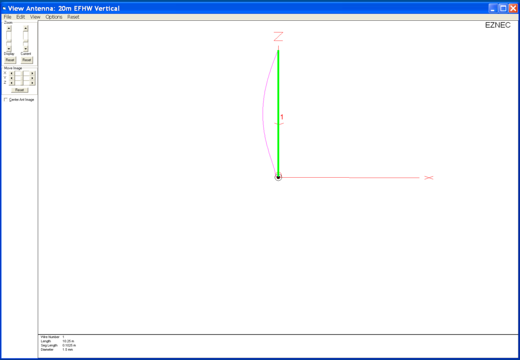
An EFHW antenna is a relatively simple affair and for 20m it’ll be somewhere around 10.25m tall depending on where on the band I resonate it.

The difficult thing about half wave or any multiple of half wave antenna is that they present a very high impedance at the feed point. Unlike a half wave dipole that is made up of two quarter wave legs that present an almost perfect match to 50 Ohm coax cable (or a 1:1 balun), the EFHW will have a much higher impedance, normally in the range of 2000 Ohms or more. Having such a high impedance also means high voltages at the ends, something to be very aware of especially if you have children or pets in the garden!

Matching to this type of antenna can be done two ways, a simple LC circuit for high impedance feed points or via a 49:1 Unun.

Since I’ve built 1:1 baluns in the past for my delta loop antennas I’ve decided to go the way of the 49:1 Unun.

Looking online for parts to build a 49:1 Unun I stumbled across UK Antennas, they seem to have a wide selection of pre-built EFHW solutions and some very nice looking 49:1 Ununs capable of handling 400w, much more than I will ever throw at it. Contacting Ian the owner of the company via Ebay I found he has a 49:1 Unun in stock that he can ship to me next day so I decided to go ahead and order one rather than source the parts and build it myself.

UK Antennas 49:1 Unun

With the Unun sorted, let’s take a look at the radiation pattern for an EFHW Vertical on the 20m band.

Since I’m looking to do mainly CW and digital modes I’ll be tuning it for the lower end of the band.

Modelling this on EzNEC I’m pleasantly surprised at the radiation pattern of such a simple vertical.

20m EFHW Vertical 3D Field Plot

To get a radiation pattern like this on the low bands requires a very large vertical, on 160m we’re talking 80m in height!

On 20m an EFHW is only around 10.25m long, very easy to put up in most U.K. sized gardens using nothing more than an extendable fibre glass pole. The 3D Field Plot shows the lovely deep null in the centre as you’d expect and a great low angle circular radiation pattern.

20m EFHW 2D Field Plot

The elevation 2D field plot really shows the beauty of this antenna.

5.62dBi at 10 Deg and 5.56dBi at 5 Deg, perfect for the long haul DX chaser. The wide deep null in the centre will help attenuate the signals arriving at high angles from the EU that plague us on the East Coast of the UK.

So, it’s time to go find some wire, get cutting and get a fibre glass extendable pole mounted in the garden ready for the arrival of the 49:1 Unun.

More soon ….

UPDATES:

More info on antenna performance here.

Going QRP with the 20m EFHW Vertical and IC-705

Keeping it simple but effective – 20m EFHW Vertical

Fun evening on 30m FT8

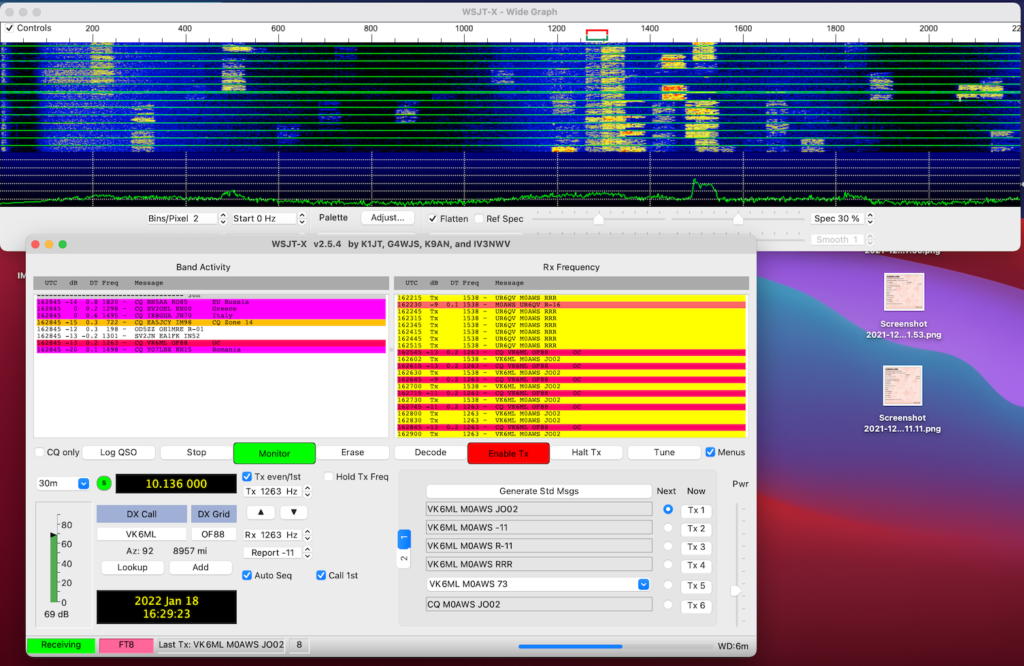
I spent yesterday evening on the 30m band running WSJT-X in FT8 mode whilst getting to know the new radio. I must say I am impressed with the Yaesu FTDX10, the receiver really is extremely good at pulling out the weakest of stations.

WSJT-X in FT8 mode running on my MacBook Pro

I have a very simple setup at the moment, just the one antenna for 30m currently so I don’t have a lot of bands available. Hopefully this will change in the coming months as I work on building a new multi band antenna for the station.

I’m still getting to know WSJT-X and FT8, it’s a new mode for me and quite different to how things were 15 years ago when I was last active.

With a little perseverance I soon got the hang of it and was working stations with ease. I’m very much a wait and pounce type DXer, so my QSO turn over is low but, I get the stations I want to work rather than just a multitude of European stations who are all on my doorstep.

It was interesting to watch the band conditions change as the grey line moved across the Atlantic. One by one countries further west started popping up on the band.

30m FT8 Early Evening view

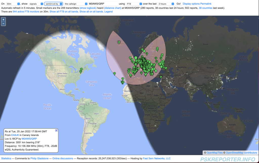
At 18:00GMT PSKReporter was showing mainly the multitude of European stations running FT8 on 30m with the Azore and Canary Islands starting to appear along with a couple of stations from the East Coast USA.

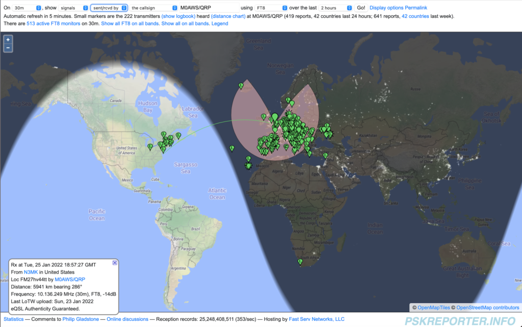
30m FT8 19:00GMT

As the grey line continued west more and more DX stations started to appear including a station in South Africa. I worked a bunch of stations in the Ukraine and Russia and then started picking off the stations in the USA one by one.

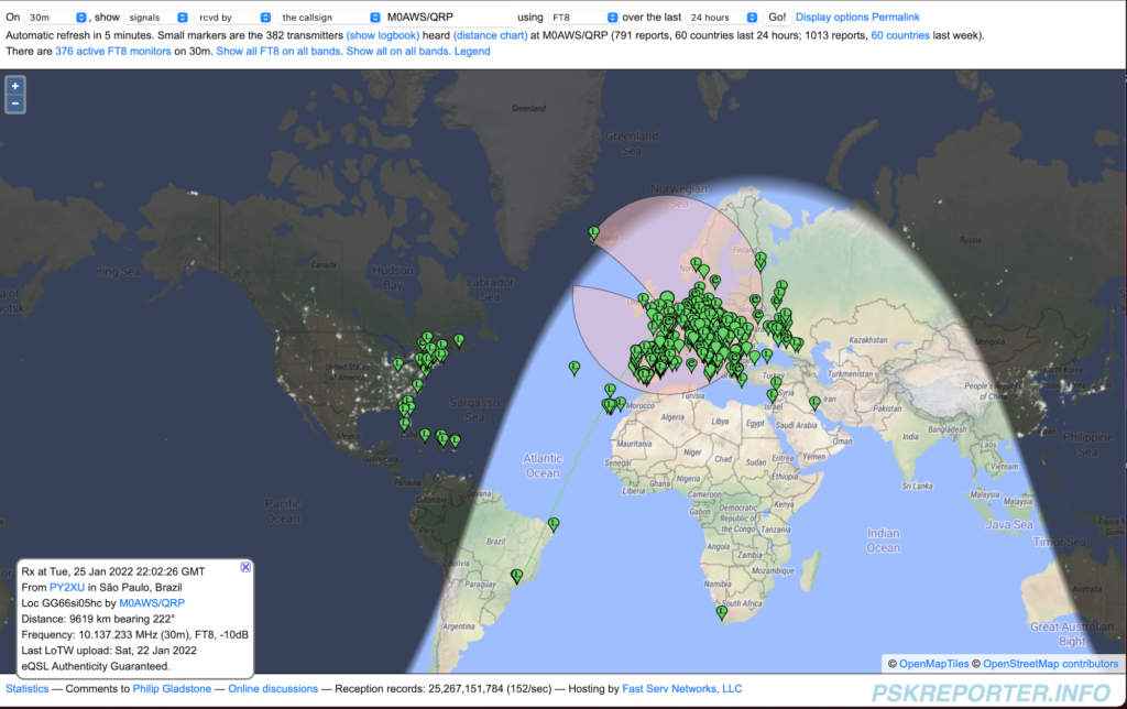
30m FT8 all stations heard (Screenshot taken next day)

By the end of the evening there were stations from South America and the Caribbean coming through. I spent over an hour trying to work CO8LY in Cuba, he was coming in at -10dB at my end but, sadly he never heard my 15w signal. I did try splitting the RX and TX frequency in WSJT-X so that my signal was to the side of the pileup but alas I never got through. Later in the evening I found CO8LY calling CQ over and over but, once again he never heard my replies. A real shame as it’s rare to hear Cuba over here on the East Coast of the U.K.

At 22:30GMT I closed the station down and headed to bed, I didn’t work a huge number of stations but, I had a lot of fun chasing the ones I wanted to get.

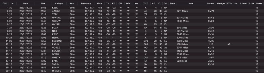
It’s interesting to note that the closest stations worked was 800 miles away, I think that is the first hop for my 30m Delta Loop Antenna. With the antenna being so quiet on receive and the FTDX10 having such a good receiver, it was very easy to pick out the stations 2000 miles or more away from my QTH. Most of the time I was able to exchange signal reports with stations that I called. It’s impressive to be able to exchange reports with stations that are -18dB or more below the noise level.

RUMlogNG List of stations worked on 30m FT8 mode

It was nice to get into Lebanon and Israel, two countries that have always been difficult to get into from my U.K. QTH.

A total of 20 stations worked, not a huge count but, it gave me some time to get used to the radio and it’s settings.

I also had a tune around 40m, the FT8 section was packed with stations from all over the world. I can’t wait to get onto 40m, it’s one of my favourite bands and I’m hoping to be able to work some good DX with QRP power levels.

I also listened on 80m and 160m, both were very active with mainly European stations on FT8 and SSB.

With my roll of coax arriving today I’l spend some time putting together a new coaxial run to the antenna and start working on an LC tuning unit for the new vertical I’m designing.

More soon …

Thoughts on a new antenna …

I’ve started thinking about antennas for the M0AWS QTH. Unfortunately we only have a typical U.K. sized garden now, which is tiny compared to the acres we had when we lived in France (F5VKM).

So, small gardens means small antennas.

The only direction I can go really is up, although most of my neighbours are very antenna unfriendly!

Like most radio amateurs in the U.K. I’m trying to find a single antenna that will give me the best performance possible on as many bands as possible.

Of course we all know there is no unicorn antenna that does it all but, with some compromise we can do fairly well on a mix of bands with a little consideration.

To this end I’ve been looking at Inverted L antennas. It’s not an antenna I have any real experience of but, it’s interesting to research.

40m End Fed Half Wave Inverted L

I started with a design for the 40m band. A simple end fed half wave inverted L antenna that consists of two parts. The vertical section is 11.95m high and the horizontal section is 8.7m long. Total length of wire is 20.65m. Modelling the antenna with 1.5mm wire it gives some surprising results.

3D Field Plot on 7.1Mhz
2D Field Plot on 7.1Mhz

As shown in the two field plots above, the antenna has an extremely low angle of max radiation making it ideal for DXing. Gain at 10 Deg is 3.99dBi, not to be sneezed at. The 3D plot shows the overall radiation pattern to be almost perfectly circular.

On the 20m band the antenna presents a favourable pattern considering it’s a full wave length long.

The angel of radiation is somewhat higher than on 40m but, this is to be expected.

2D Field Plot on 14.1Mhz

On the 20m Band the antenna gives a gain of 7.07dBi at 25 Deg. A higher angle of radiation than on the 40m band but, still very usable. At 5 Deg there is 4.29dBi of gain which makes it ideal for DXing.

3D Field Plot on 14.1Mhz

On the 15m band the pattern isn’t as good as on 40m & 20m however, it would still be usable.

3D Field Plot on 21.1Mhz
2D Field Plot on 21.1Mhz

With a gain of 6.04dBi at 25 Deg it should perform very well on the 15m band. At 10 Deg there is a gain of 1.12dBi. The overall pattern is a bit lopsided and it also has more high angle radiation than I really want but, like all multi band antennas there’s always a compromise.

Next I modelled the antenna on the 10m band, the 3D pattern is rather alarming but, it has potential.

3D Field Plot on 28.1Mhz

There’s a lot of high angle on the 10m band and a somewhat out of balance pattern but, there’s also gain to be had at a lower angle too.

2D Field Plot on 28.1Mhz

The main gain is 6.37dBi at 45 Deg, ideal for short hop communications however, there is 3.58dBi of gain to be had at 10 Deg, much better for DXing.

It’s not ideal for 10m by any means but, when you take into account that the antenna is 2 wave lengths long it’s hardly surprising.

I’ve still got a lot more work to do on this modelling but, it has huge potential.

I’ve not even started thinking about impedance matching yet, I know it’s going to be a monster and nowhere near 50 Ohms but, I’m sure a simple LC network will do magic with matching it to the transceiver.

More soon …

First time on air in 15 years!

I had a fun couple of hours this afternoon. I found my 30m band Delta Loop antenna packed away in the loft, got it out and put it up in the garden, 1.2:1 SWR across the band and I was soon listening to Morse conversations on the band.

WSJT-X FT8 mode on the 30m Band

Connecting my MacBook Pro to the Yaesu FTDX10 I soon had WSJT-X FT8 mode running and started working a few stations. I found I needed to reduce the output from the Apple MacBook so that the ALC on the radio barely moved, this tidied up the transmitted signal and ensured I wasn’t splattering. Setting the radio O/P to 10w my first contact was into Cyprus, followed by a couple of contacts into Ukraine.

One thing I did notice was how strong many of the signals were. I’m sure some operators are using huge power levels on the FT8 part of the band with some of the signals +10db or more over S9. FT8 is supposed to be a weak signal mode, there really is no need for huge power levels. The funny thing is, many of these high powered stations are heard by DX stations but, they don’t hear the them coming back to them, classic case of shouting louder than they can hear. There really is no point being heard if your station isn’t capable of hearing the replies coming back.

I’d forgotten how good my Delta Loop antennas are, super quiet on receive and great for finding weak signals on the band.

I checked the PSK Reporter site to see where I’d been heard and was pleasantly surprised to see I was heard in Australia! I did call an Australian station but, never got a reply from him, so it was great to get confirmation that my signal was making the trip.

PSK Reporter showing where my signal was heard

Due to the direction of my garden the antenna is beaming north west / south east, long path to Australia. It’s amazing how 10w of RF can cover almost 9000 miles!

So what next?

Well, I need to purchase some coaxial cable as the bits I have from France have gone stiff/brittle and really are past their shelf life.

I also need to buy some wire to start making some antennas. I’m going to put together a top loaded vertical for the 160/80/40m bands and some delta loops for the higher bands.

I’m also going to make some end fed half wave verticals for 20m and upwards.

Lots to do, if only the weather would improve!

More soon …

New radio ordered!

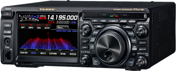
Yaesu FTDX10

After much research and decision making I finally decided to purchase a Yaesu FTDX10 HF/6m transceiver. Out of all the radios on the market and there are many, this is the one that I’ve decided has the functionality I need and gives the best performance for the money.

I really liked the little Icom IC705 but, it’s a lot of money for a QRP radio and performance wise isn’t as good as the FTDX10.

I also liked the Icom IC7300 but, this is now a 7 year old radio (at the time of writing this) and the tech has moved on substantially since then.

The FTDX10 is a hybrid SDR radio that combines the best of both worlds to give a performance level that exceeds many of the other transceivers on the market today. Ranking 3rd on the Sherwood Engineering Receiver Test Data it’s a great radio for the money.

The other thing that really impressed me with the FTDX10 was the DNR and Contour noise reduction functionality. Watching videos online it is amazing how when these two tools are used correctly together extremely weak CW signals can be recovered on a noisy band.

So, with the radio ordered from Martin Lynch and Sons I now need to start building some antennas and impedance matching circuits so that I can get on air once the transceiver arrives.

More soon …