I’ve had this antenna model for ages now but, never got round to putting it onto the website until Alex, GM5ALX was talking about making one the other day whilst chatting on the QO-100 satellite.
The 20m band delta loop follows exactly the same design principles as all the other delta loop designs I’ve already put on the website. They are designed such that they present a 50 ohm impedance at the feed point and thus have no requirement for complex impedance matching circuits/transformers.
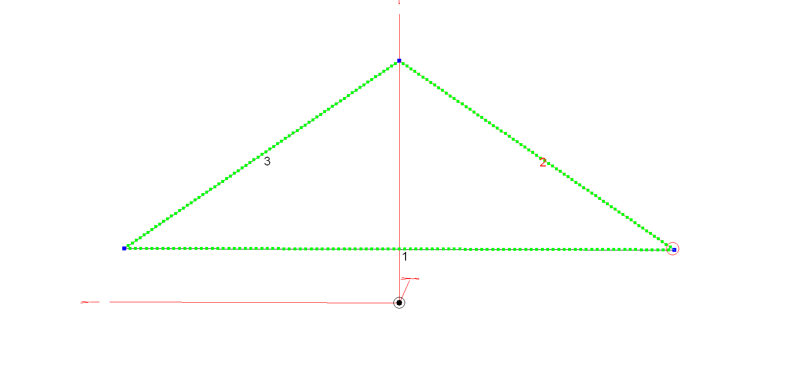
M0AWS 20m Band Delta Loop Antenna – Antenna View
The dimensions for the antenna are as follows:
Wire 1 – Horizontal exactly 1m above the ground for its entire 10.2m length. Wires 2 & 3 are exactly 6.18m long each with the top being 4.5m above the ground.
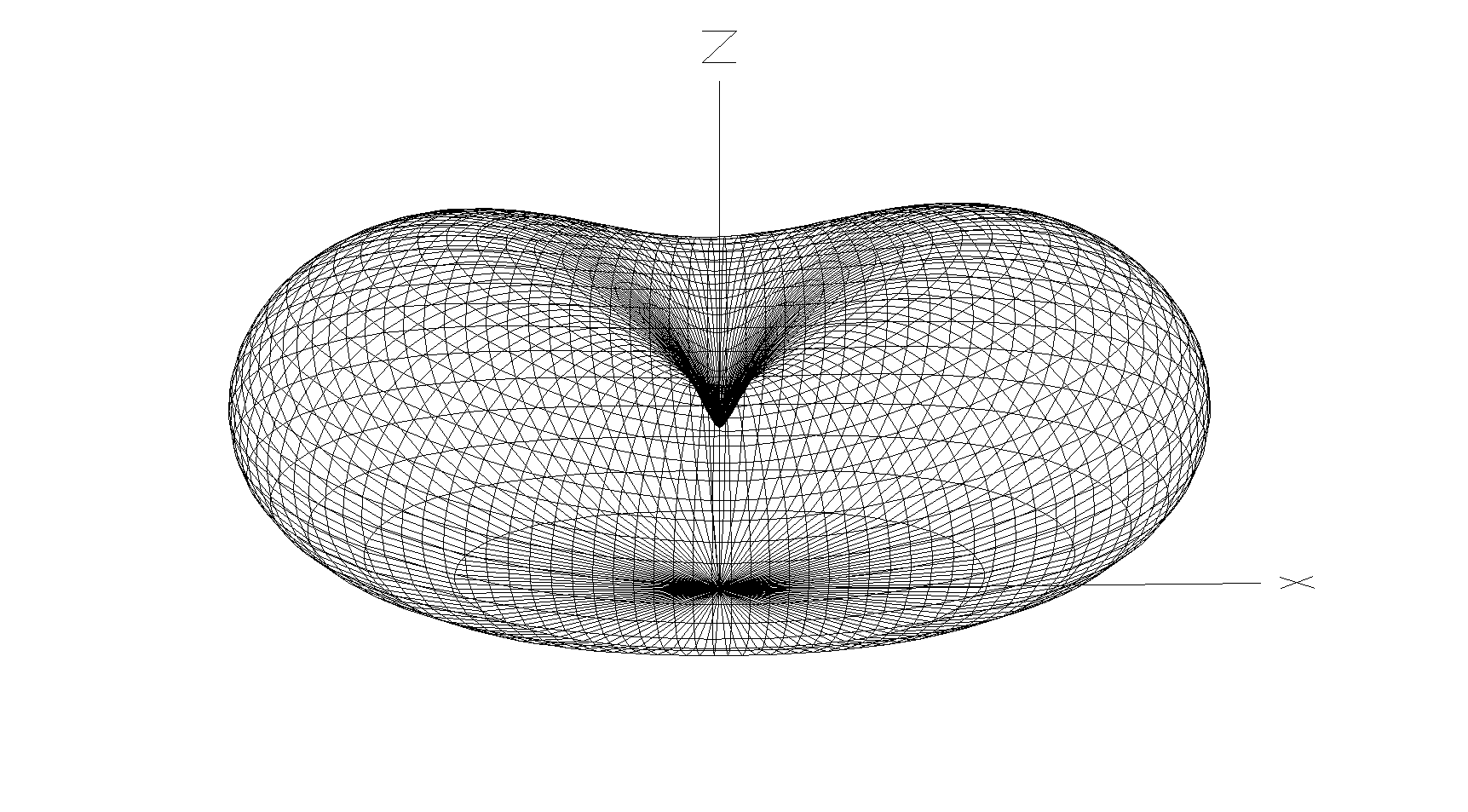
M0AWS 20m Band Delta Loop Antenna – 3D Far Field Plot
The 3D far field plot shows a typical delta loop radiation pattern with the maximum radiation through the loop and a deep null in the centre.
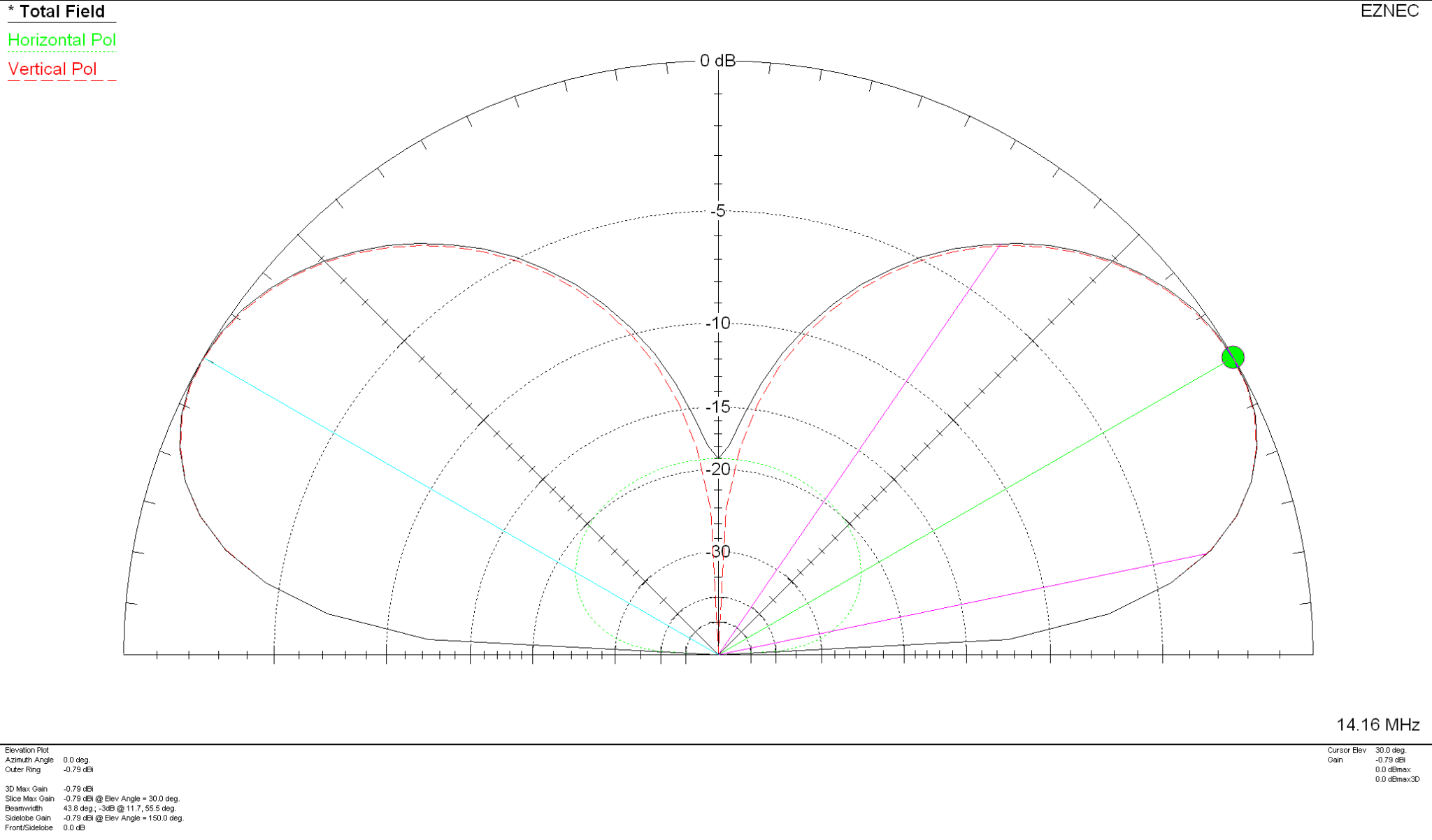
M0AWS 20m Band Delta Loop Antenna – 2D Far Field Plot
The 2D elevation plot shows that the antenna will give a maximum gain of -0.79dBi at 30 degrees when used over average/poor soil types. If like me you use your Delta Loop antennas on the beach then the antenna will present considerably more gain as it will benefit from the salt water reflection.
If you want to lower the angle of maximum radiation and increase the gain over average ground just raise the antenna up so that the top is around 7m above ground. This will give a much lower angle of radiation and improve the gain figure by 2-3dBi. Don’t forget that if you raise the antenna the point of resonance will also rise in frequency and so you may need to shorten the wires a little to get the point of resonance back to where you want it.
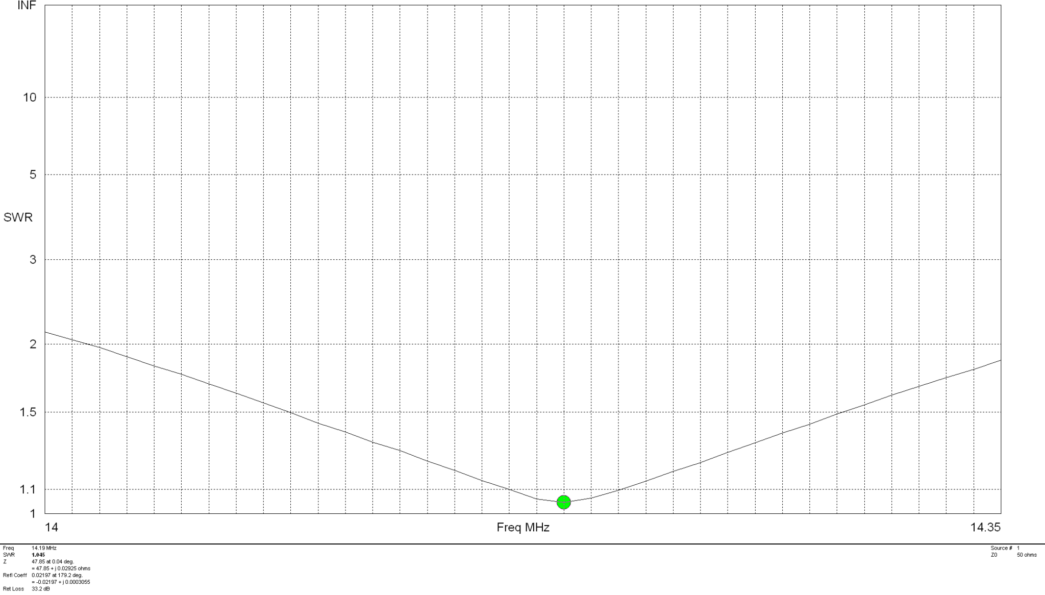
The SWR plot shows that the antenna will have a fairly wide bandwidth and match to 50 ohm coax extremely well. The antenna is designed to be fed in one of the lower corners via a 1:1 balun for best results.
M0AWS 20m Band Delta Loop Antenna – SWR Curve
Summary:
Total Wire Length: 22.56m Horizontal Wire Length: 10.2m @ 1m above ground Diagonal Wire Lengths: 6.18m Wire Dia: 2.5mm Height at Centre: 4.5m Feed Type: 1:1 Balun in bottom corner (Can use coax if necessary) Impedance: 50 Ohm SWR: <1.5:1 at resonance
Since setting up the new HAM station here in the UK the one band I’ve not yet got back onto is 160m, one of my most favourite bands in the HF spectrum and one that I was addicted to when I live in France (F5VKM).
Having such a small garden here in the UK there is no way I can get any type of guyed vertical for 160m erected and so I needed to come up with some sort of compromise antenna for the band.
Only being interested in the FT4/8 and CW sections of the 160m band I calculated that I could get an inverted-L antenna up that would be reasonably close to resonant. It would require some additional inductance to get the electrical length required and some impedance matching to provide a 50 Ohm impedance to the transceiver.
Measuring the garden I found I could get a 28m horizontal section in place and a 10m vertical section using one of my 10m spiderpoles. This would give me a total of 38m of wire that would get me fairly close to the quarter wave length.
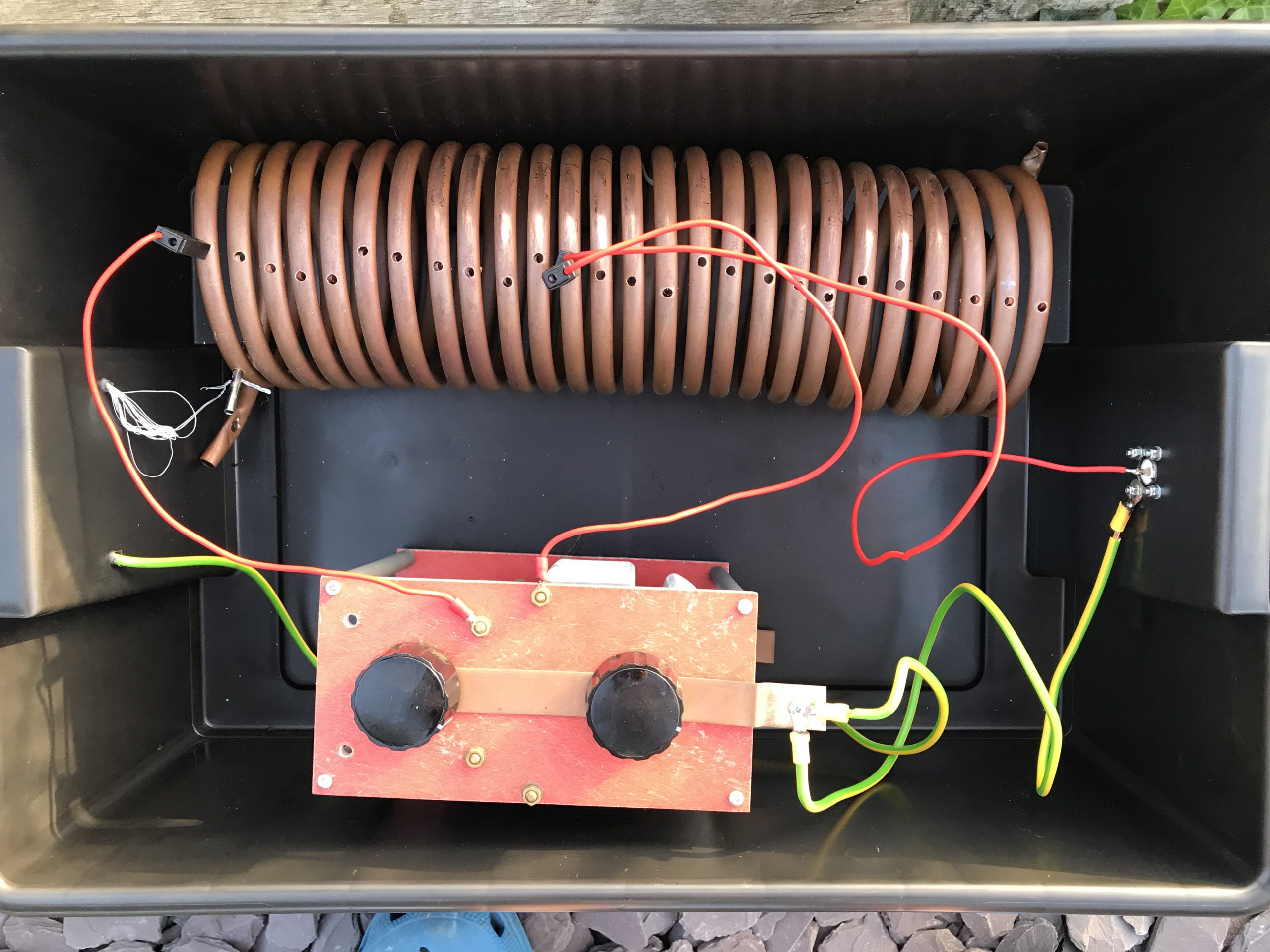
For impedance matching I decided to make a Pi-Network ATU. I’ve made these in the past and found them to be excellent at matching a very wide range of impedances to 50 Ohm.
M0AWS Homebrew Pi-Network ATU
Since I still had the components of the Pi-Network ATU that I built when I lived in France I decided to reuse them as it saved a lot of work. The inductor was made from some copper tubing I had left over after doing all the plumbing in the house in France and so it got repurposed and formed into a very large inductor. The 2 x capacitors I also built many years ago and fortunately I’d kept locked away as they are very expensive to purchase today and a lot of work to make.
Getting the Inverted-L antenna up was easy enough and I soon had it connected to the Pi-Network ATU. I ran a few radials out around the garden to give it something to tune against and wound a 1:1 choke balun at the end of the coax run to stop any common mode currents that may have appeared on the coax braid.
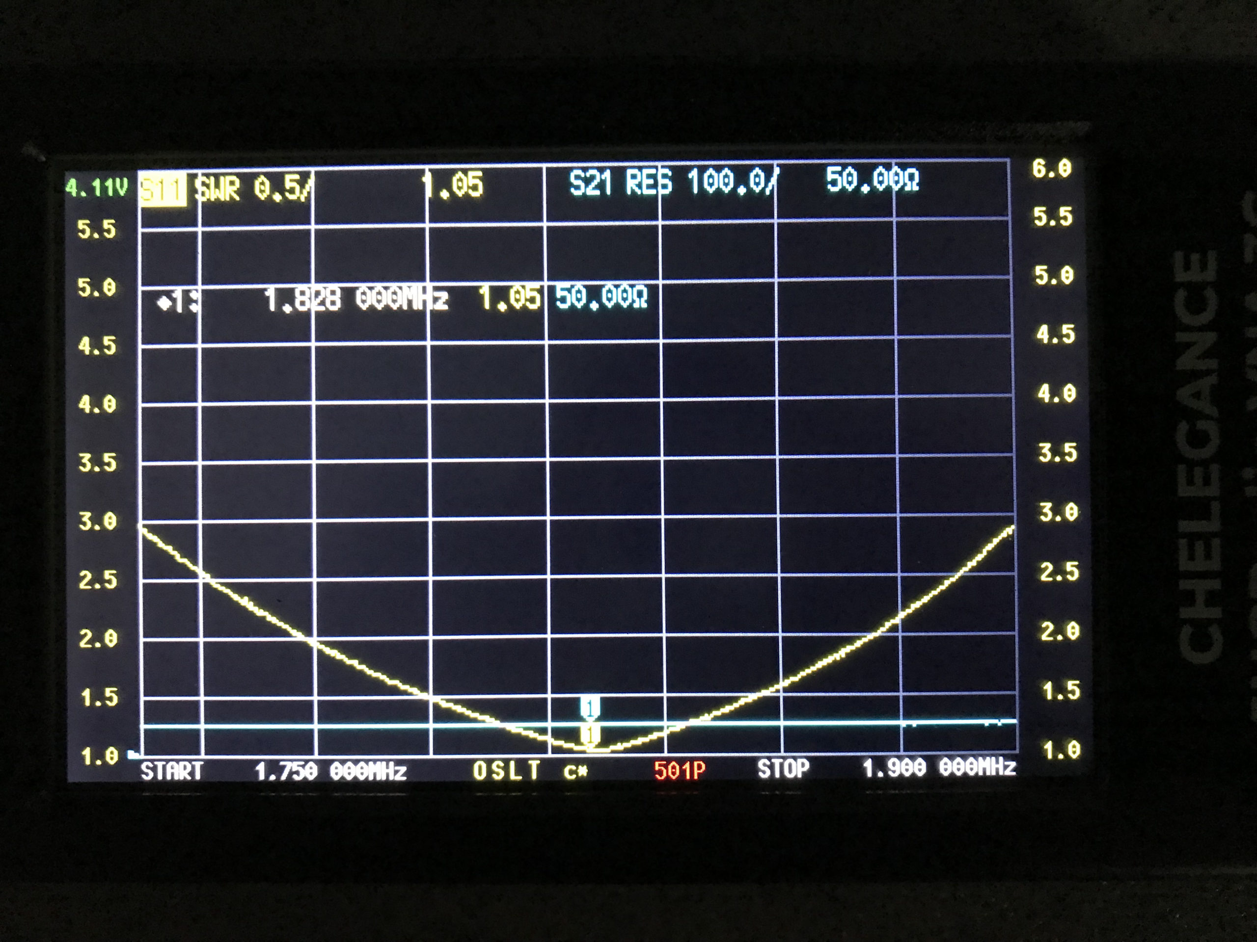
Connecting my JNCRadio VNA I found that the Inverted-L was naturally resonant at 2.53Mhz, not too far off the 1.84Mhz that I needed. Adding a little extra inductance and capacitance via the ATU I soon had the antenna resonant where I wanted it at the bottom of the 160m band.
M0AWS 160m Inverted L Antenna SWR Curve
With the SWR being <1.5:1 across the CW and FT8 section of the band I was ready to get on 160m for the first time in a long.
Since it’s still summer in the UK I wasn’t expecting to find the band in very good shape but, was pleasantly surprised. Switching the radio on before full sunset I was hearing stations all around Europe with ease. In no time at all I was working stations and getting good reports using just 22w of FT8. FT8 is such a good mode for testing new antennas.
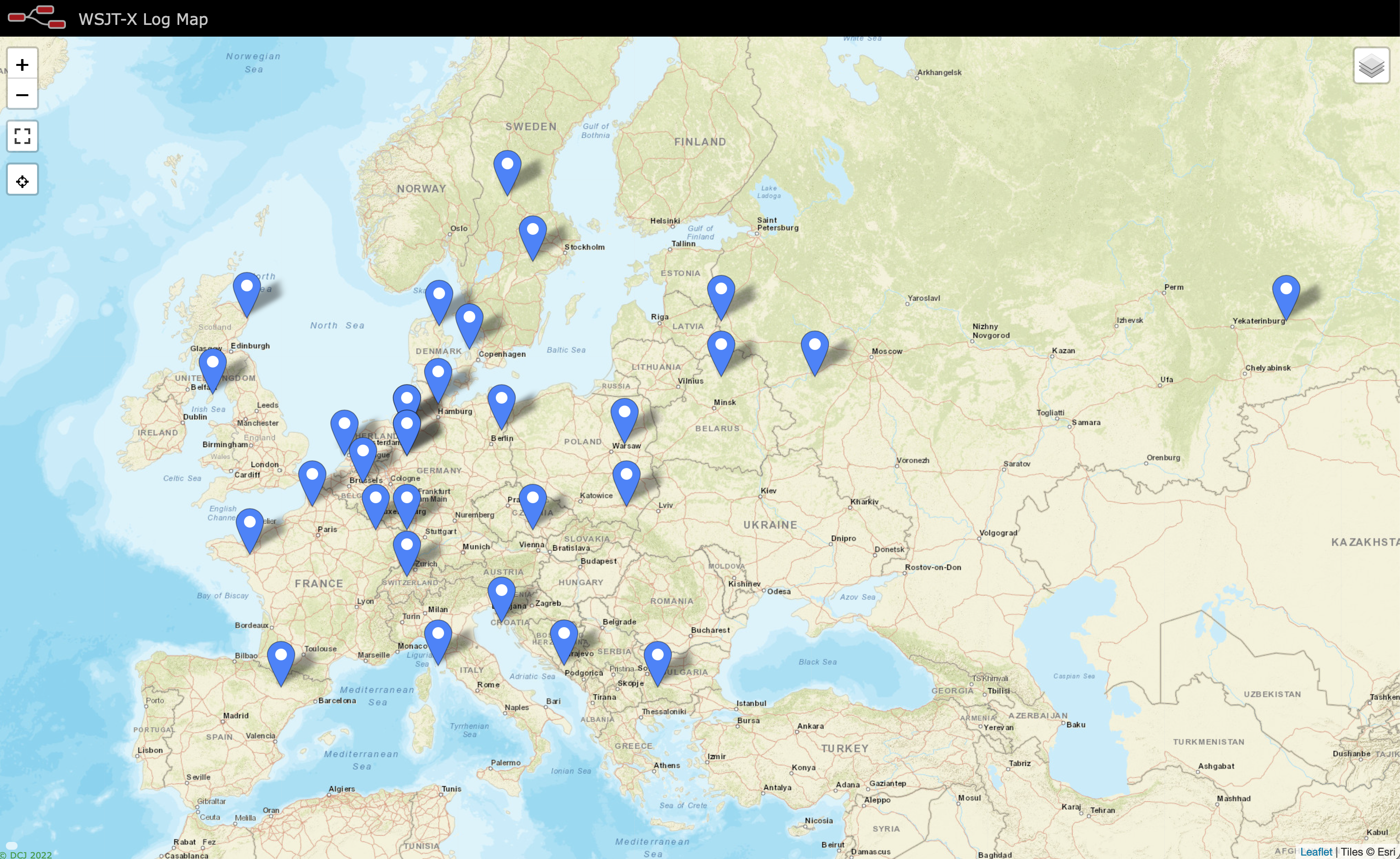
As the sky got darker the distance achieved got greater and over time I was able to work into Russia with the longest distance recorded being 2445 Miles, R9LE in Tyumen Asiatic Russia.
In no time at all I’d worked 32 stations taking my total 160m QSOs from 16 to 48. I can’t wait for the long, dark winter nights to see how well this antenna really performs.
M0AWS Map showing stations worked on 160m using Inverted L Antenna
The map above shows the locations of the stations worked on the first evening using the 160m Inverted-L antenna. As the year moves on and we slowly progress into winter it will be fun to start chasing the DX again on the 160m band..
UPDATE 6th October 2023. Been using the antenna for some time now with over 100 contacts on 160m. Best 160m DX so far is RV0AR in Sosnovoborsk Asiatic Russia, 3453 Miles using just 22w. Pretty impressive for such a low antenna on Top Band.
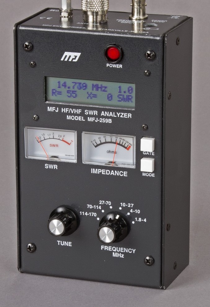
Many years ago I had an MFJ-259B antenna analyser that I used for all my HF antenna projects. It was a simple device with a couple of knobs, an LCD display and a meter but, it provided a great insight into the resonance of an antenna.
MFJ-259B Antenna Analyser
Today things have progressed somewhat and we now live in a world of Vector Network Analysers that not only display SWR but, can display a whole host of other information too.
Being an avid antenna builder I’ve wanted to buy an antenna analyser for some time but, now that I’m into the world of QO-100 satellite operations using frequencies at the dizzy heights of 2.4GHz I needed something more modern.
If you search online there are a multitude of Vector Network Analysers (VNAs) available from around the £50.00 mark right up to £1500 or more. Many of the VNAs you see on the likes of Amazon and Ebay come out of China and reading the reviews they aren’t particularly reliable or accurate.
After much research I settled on the JNCRadio VNA 3G, it gets really good reviews and is very sensibly priced. Putting a call into Gary at Martin Lynch and Sons (MLANDS) we had a long chat about various VNAs, the pros and cons of each model and the pricing structure. It was tempting to spend much more on a far more capable device however, my sensible head kicked in and decided many of the additional features on the more expensive models would never get used and so I went back to my original choice.
Gary and I also had a long chat about building a QO-100 ground station, using NodeRed to control it and how to align the dish antenna. The guys at MLANDS will soon have a satellite ground station on air and I look forward to talking to them on the QO-100 transponder.
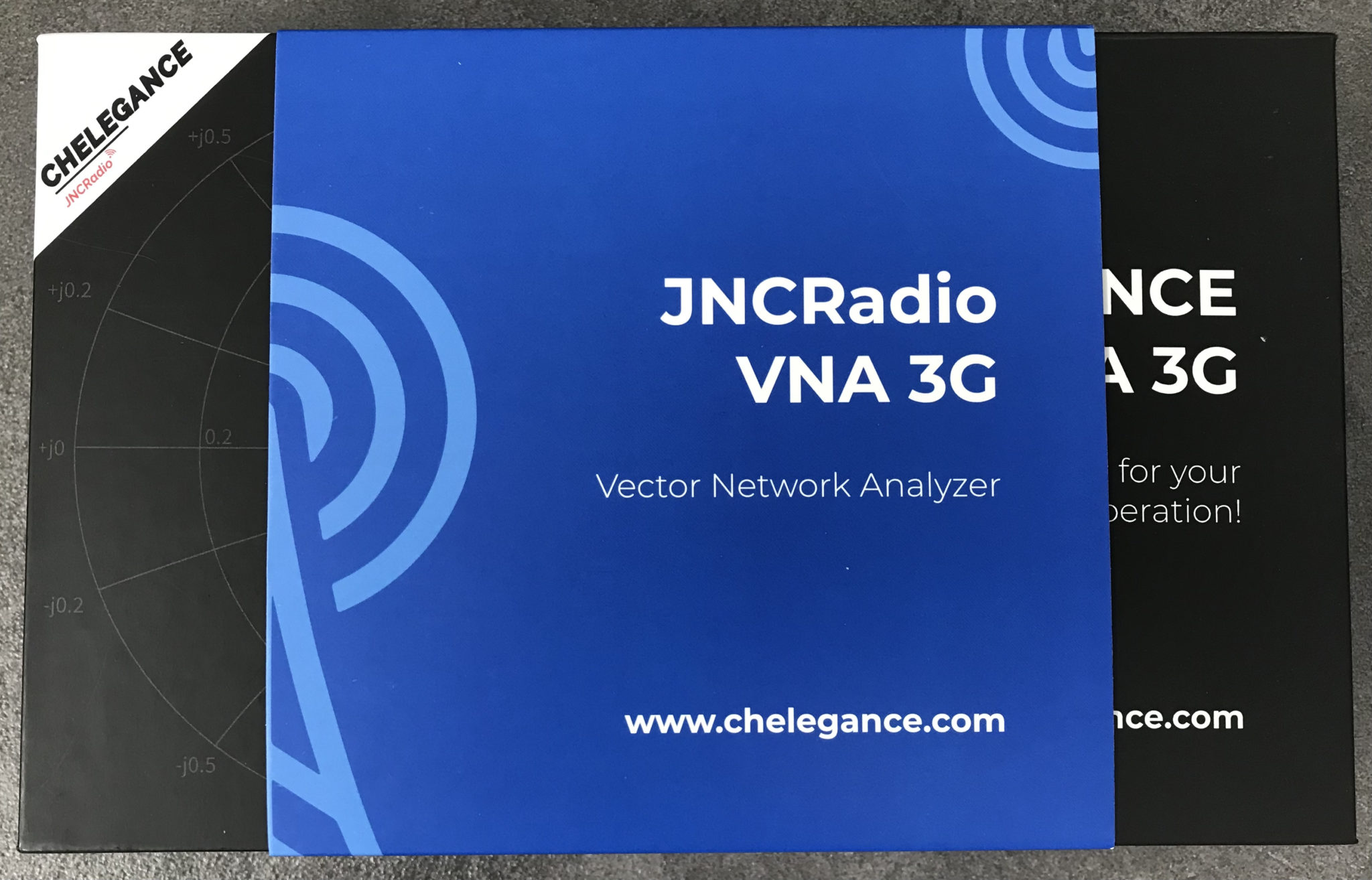
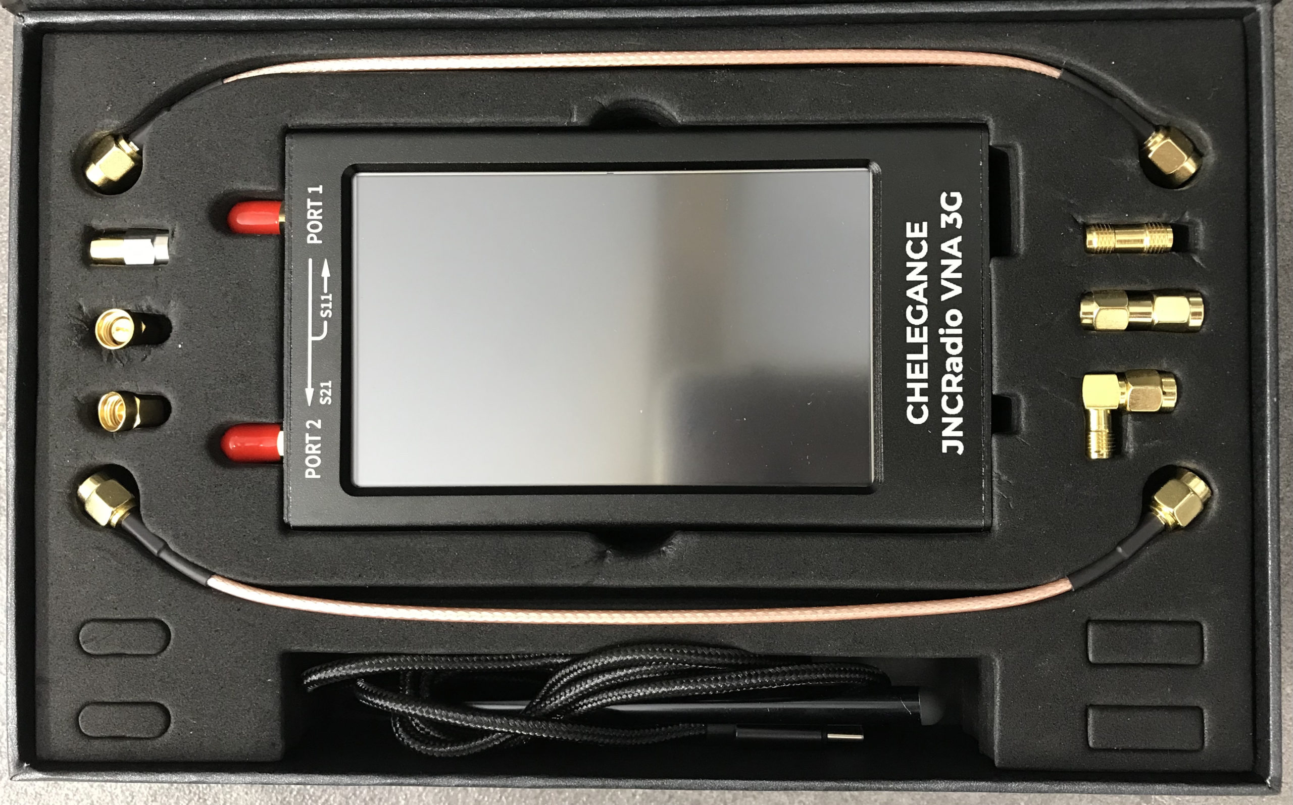
M0AWS – JNCRadio VNA 3G PackagingM0AWS – JNCRadio VNA 3G in box with connectors and cables
Initially I wanted to check the SWR of my QO-100 2.4GHz IceCone Helix antenna on my satellite ground station to ensure it was resonant at the right frequency. Hooking the VNA up to the antenna feed was simple enough using one of the cables provided with the unit and I set about configuring the start and stop stimulus frequencies (2.4GHz to 2.450GHz) for the sweep to plot the curve.
The resulting SWR curve showed that the antenna was indeed resonant at 2.4GHz with an SWR of 1.16:1. The only issue I had was that in the bright sunshine it was hard to see the display and impossible to get a photo. Setting the screen on the brightest setting didn’t improve things much either so this is something to keep in mind if you plan on using the device outside in sunny climates.
(My understanding is that the Rig Expert AA-3000 Zoom is much easier to see outside on a sunny day however, it will cost you almost £1200 for the privilege.)
A couple of days later I decided to check the SWR of my 20m band EFHW vertical antenna. I’ve known for some time that this antenna has a point of resonance below 14MHz but, the SWR was still low enough at the bottom of the 20m band to make it useable.
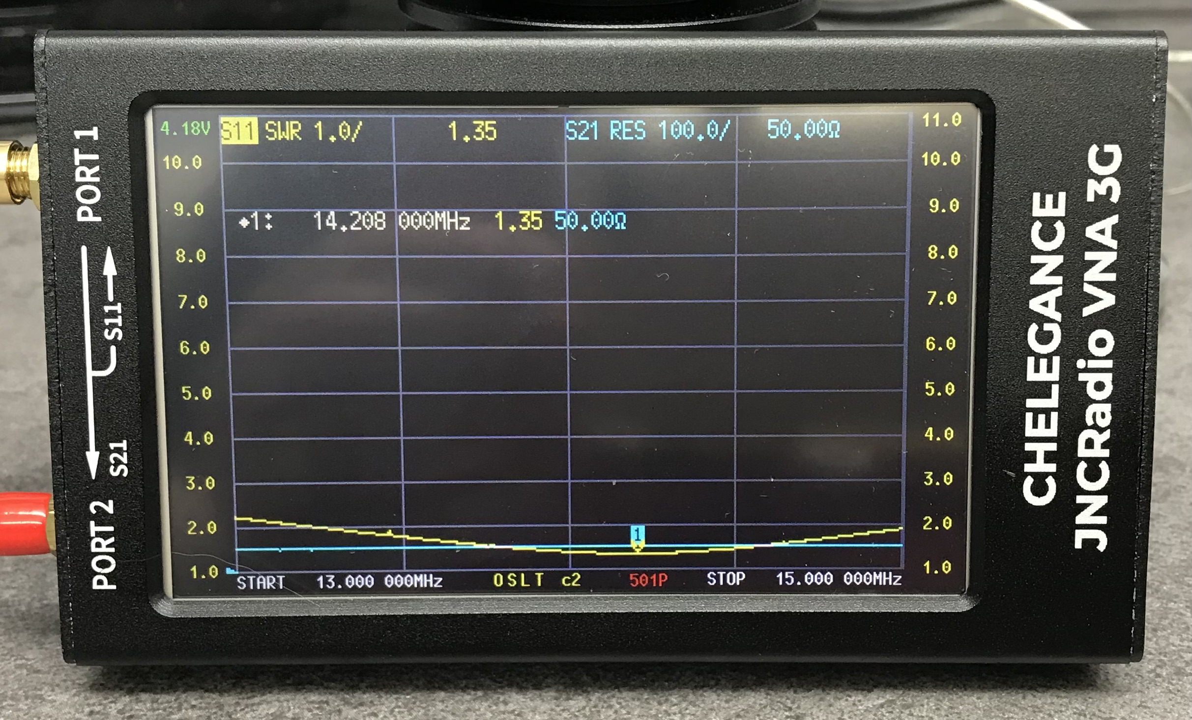
Hooking up the VNA I could see immediately that the point of resonance was at 13.650Mhz, well low of the 20m band and so I set about shortening the wire until the point of resonance moved up into the band.
JNCRadio VNA3G showing 20m Band EFHW Resonance
With a little folding back of wire I soon had the point of resonance nicely into the 20m band with a 1.35:1 SWR at 14.208Mhz. This provides a very useable SWR across the whole band but, I decided I’d prefer the point of resonance to be slightly lower as I tend to use the antenna mainly on the CW & FT4/8 part of the band with my Icom IC-705 QRP rig.
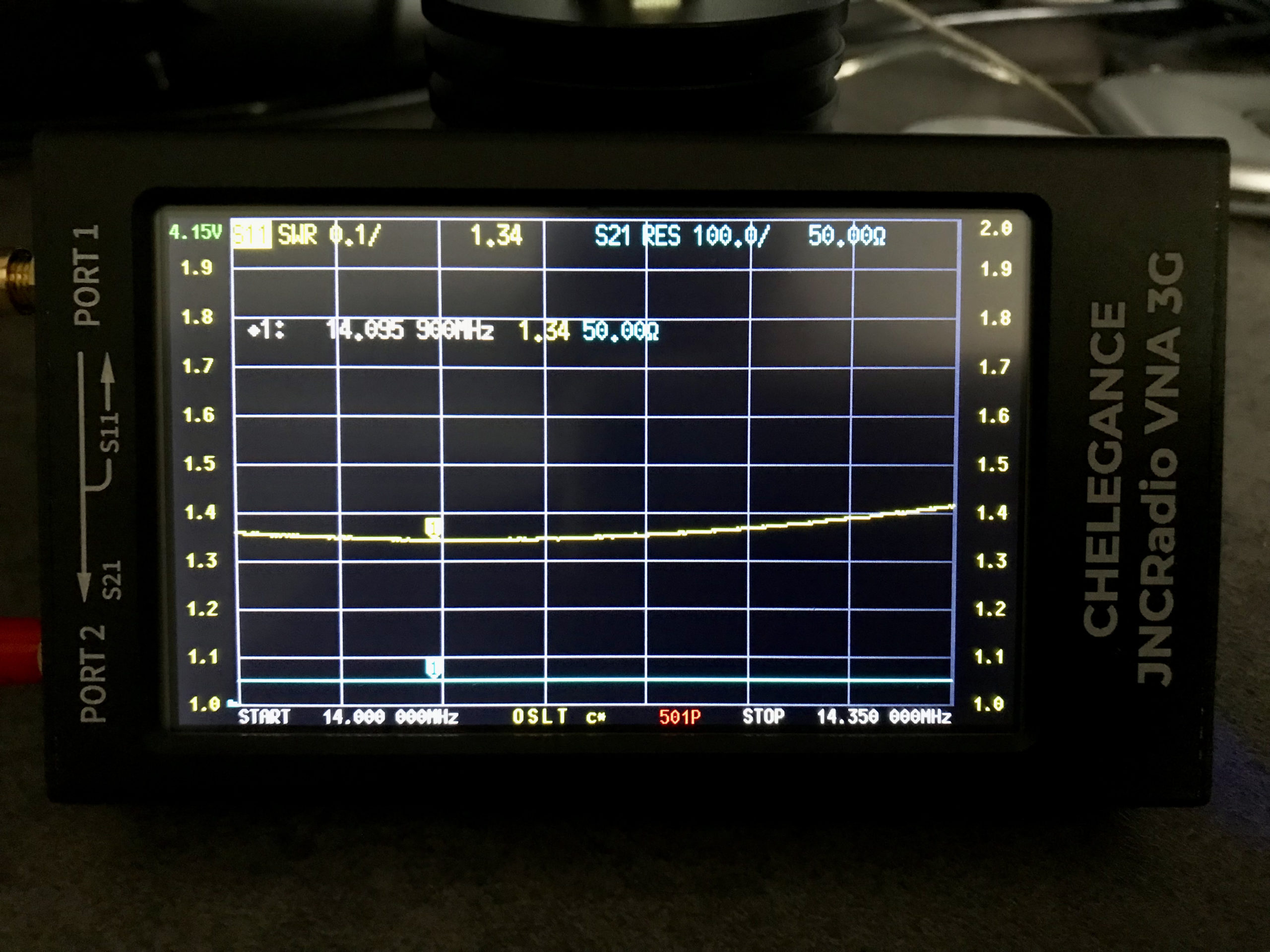
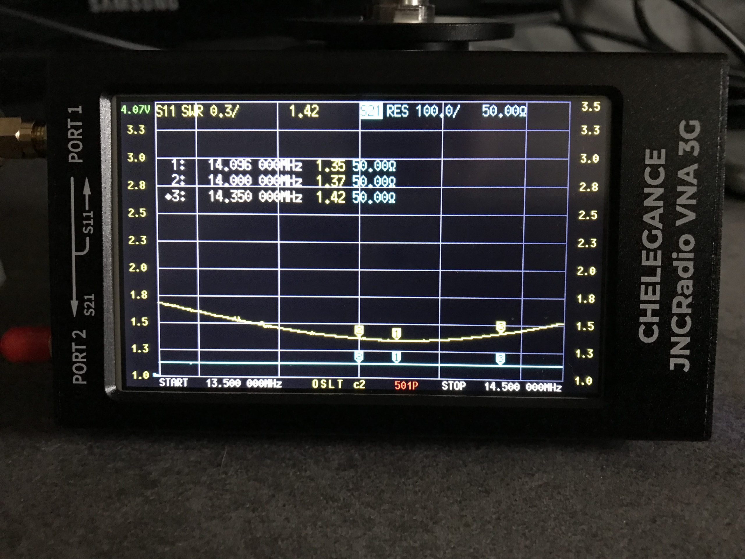
Popping out into the garden once more I lengthened the wire easily enough by reducing the fold back and brought the point of resonance down to 14.095Mhz.
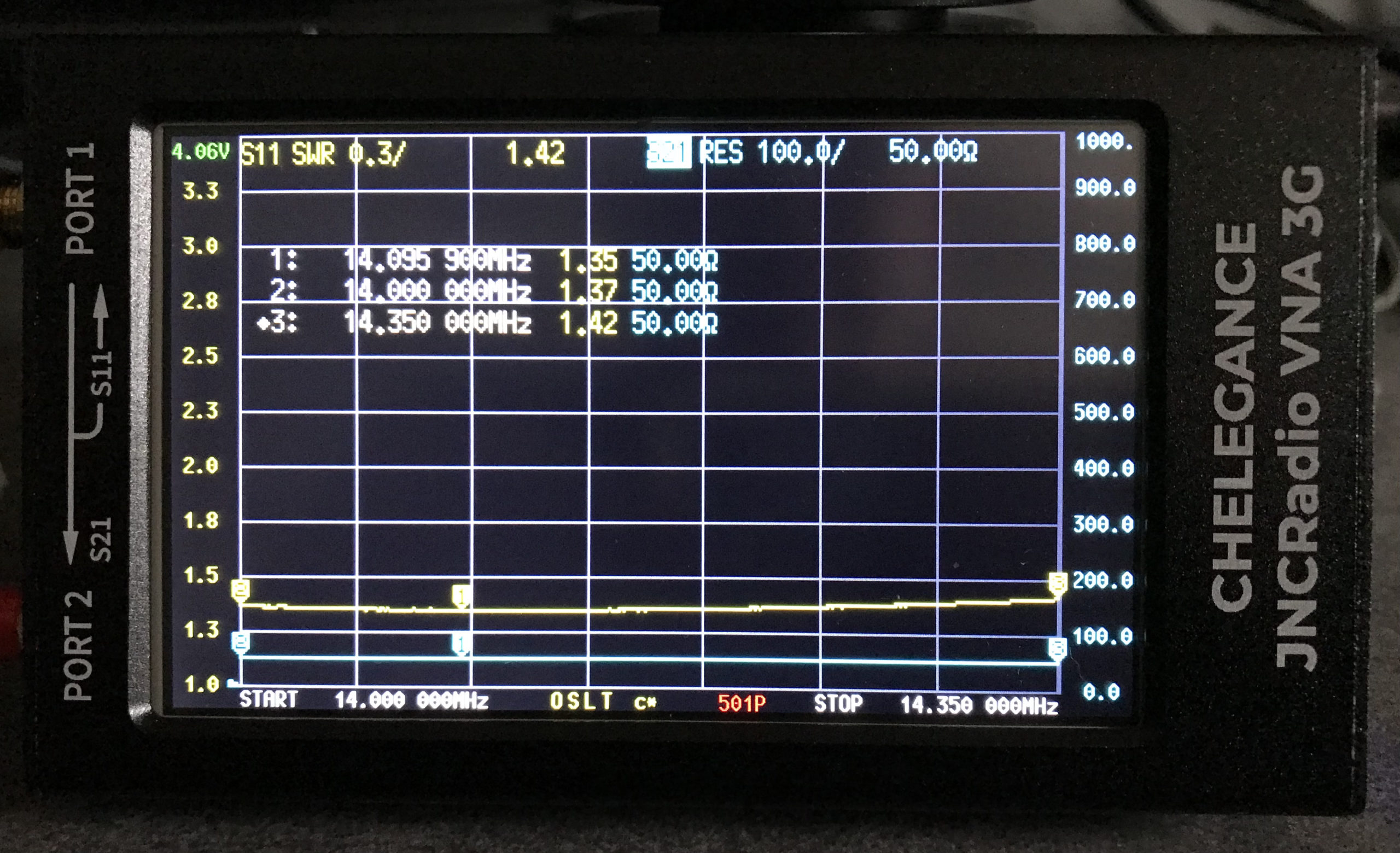
JNCRadio VNA3G showing 20m Band EFHW Resonance 14Mhz to 14.35Mhz Sweep
The VNA automatically updated the display realtime to show the new point of resonance on the 4.3in colour screen. I also altered the granularity of the SWR reading on the Y axis to show a more detailed view of the curve and reduced the frequency range on the X axis so that it showed a 14Mhz to 14.35Mhz sweep. With an SWR of 1.34:1 at 14.095Mhz and a 50 Ohm impedance, the antenna is perfectly resonant where I want it.
It’s interesting to note that the antenna is actually useable between 13.5Mhz and 14.5Mhz with a reasonable SWR across the entire frequency spread. Setting 3 markers on the SWR curve I could see at a glance the SWR reading at 14Mhz (Marker 2) , 14.350Mhz (Marker 3) and the minimum SWR reading at 14.095Mhz (Marker 1).
I’ve been gradually building my QO-100 ground station over the last few months and have had the receive path working for some time now. One of the things I really miss with the Funcube Dongle Pro+ (FCD) SDR is a real VFO knob for changing frequency.
My QO-100 Node Red dashboard is configured so that I can have the FCD track the uplink frequency from the IC-705 but, sometimes I use the FCD without the IC-705 in the shack and so a physical VFO would be handy.
Many years ago when I lived in France (F5VKM) I had a Flexradio Flex-3000 SDR, a great radio in it’s time and one that gave me many hours of enjoyment. One addition I bought for that station was a Griffin Technology Powermate VFO knob. It worked extremely well with the PowerSDR software for the Flex-3000 and I used it for many years.
Many years later I’m back in the UK and much of my equipment is packed away in the attic, including the Griffin Technology Powermate VFO.
I decided to dig it out and see if I could get it working with GQRX SDR software. Sadly I couldn’t get it working with GQRX however, I did find a way of getting it working with Node Red and thus could add it to my QO-100 Node Red Dashboard and then control GQRX with it via a simple Node Red flow.
Griffin Technology Powermate VFO
Plugging the Powermate VFO into my Kubuntu PC it wasn’t immediately recognised by the Linux O/S. After a little searching I found the driver on Github. I added the PPA to my aptitude sources and installed the driver using apt.
Once installed the default config for the Powermate device is to control the default audio device volume. To make the device available for use as a VFO knob you need to change the configuration so that the default setting is disabled. To do this is relatively easy, just edit the config file using your favourite command line editor (Vi/Vim in my case) and add the following entry.
vi /etc/powermate.toml

# Entry to control HDMI volume with Powermate
#sink_name = "alsa_output.pci-0000_01_00.1.hdmi-stereo"

# Set powermate not to work with volume control
sink_name = ""
As shown above, comment out the default “sink_name” entry (Yours may be different depending on audio device in your PC) and add in the Powermate “sink_name” entry that effectively assigns it to nothing.
Once this is done, save the file and exit your editor and then reboot the PC.
Next you’ll need to install a small program called evtest.
sudo apt install evtest
To check the evtest program has installed correctly, plugin your Powermate VFO to any available USB port and run the following command in a terminal.
evtest /dev/input/powermate
Turning the Powermate knob you should see output on the screen showing the input from the device. You should also see BTN events for each press of the Powermate device.
Input driver version is 1.0.1
Input device ID: bus 0x3 vendor 0x77d product 0x410 version 0x400
Input device name: "Griffin PowerMate"
Supported events:
  Event type 0 (EV_SYN)
  Event type 1 (EV_KEY)
    Event code 256 (BTN_0)
  Event type 2 (EV_REL)
    Event code 7 (REL_DIAL)
  Event type 4 (EV_MSC)
    Event code 1 (MSC_PULSELED)
Properties:
Testing ... (interrupt to exit)
Event: time 1685816662.086666, type 2 (EV_REL), code 7 (REL_DIAL), value -1
Event: time 1685816662.086666, -------------- SYN_REPORT ------------
Event: time 1685816662.318638, type 2 (EV_REL), code 7 (REL_DIAL), value -1
Event: time 1685816662.318638, -------------- SYN_REPORT ------------
Event: time 1685816662.574615, type 2 (EV_REL), code 7 (REL_DIAL), value -1
Event: time 1685816662.574615, -------------- SYN_REPORT ------------
Event: time 1685816663.670461, type 2 (EV_REL), code 7 (REL_DIAL), value 1
Event: time 1685816663.670461, -------------- SYN_REPORT ------------
Event: time 1685816664.030421, type 2 (EV_REL), code 7 (REL_DIAL), value 1
Event: time 1685816664.030421, -------------- SYN_REPORT ------------
Event: time 1685816664.334389, type 2 (EV_REL), code 7 (REL_DIAL), value 1
Event: time 1685816664.334389, -------------- SYN_REPORT ------------
Event: time 1685816665.334255, type 1 (EV_KEY), code 256 (BTN_0), value 1
Event: time 1685816665.334255, -------------- SYN_REPORT ------------
Event: time 1685816665.558230, type 1 (EV_KEY), code 256 (BTN_0), value 0
Event: time 1685816665.558230, -------------- SYN_REPORT ------------
Event: time 1685816666.030161, type 1 (EV_KEY), code 256 (BTN_0), value 1
Event: time 1685816666.030161, -------------- SYN_REPORT ------------
Event: time 1685816666.182151, type 1 (EV_KEY), code 256 (BTN_0), value 0
Event: time 1685816666.182151, -------------- SYN_REPORT ------------
At this point you’re ready to stop evtest (CTRL-C) and then create the following little BASH shell script that Node Red will run to collect the O/P from the Powermate USB device.
#!/bin/bash

###############################################
# Griffin Technology Powermate control script #
# for Node Red.                               #
#                                             #
# 04/06/23 - M0AWS - v0.1                     #
#                                             #
###############################################

VAL="1"
echo "STEP-1Hz"

/usr/bin/evtest /dev/input/powermate | while read LINE
do
   case $LINE in

      *"(REL_DIAL), value 1") echo "$VAL"
           ;;

      *"(REL_DIAL), value -1") echo "-$VAL"
           ;;

      *"(BTN_0), value 1") case $VAL in

                              "1") VAL="10"
                                   echo "STEP-10Hz"
                                      ;;

                             "10") VAL="100"
                                   echo "STEP-100Hz"
                                      ;;

                             "100") VAL="1000"
                                    echo "STEP-1Khz"
                                       ;;

                             "1000") VAL="10000"
                                     echo "STEP-10Khz"
                                         ;;

                             "10000") VAL="1"
                                       echo "STEP-1Hz"
                                          ;;
                              esac
                                 ;;
        esac
done
Once the BASH script is copied and pasted into a file called powermate.sh you need to make it executable by using the following command.
chmod 700 ./powermate.sh
If you now run the shell script in a terminal you’ll see a similar output to that shown below from the device when used.
As you can see above the shell script outputs a positive or negative number for VFO tuning and changes the VFO step size each time the Powermate is depressed.
Getting this output from the BASH shell script into Node Red is really simple to achieve using just 3 or 4 nodes.
In the Node Red development UI create the following nodes.
Griffin Powermate Node Red Nodes
The first node in the flow is a simple inject node, here I called it trigger. This sends a timestamp into the next node in the flow at startup to set the flow running.
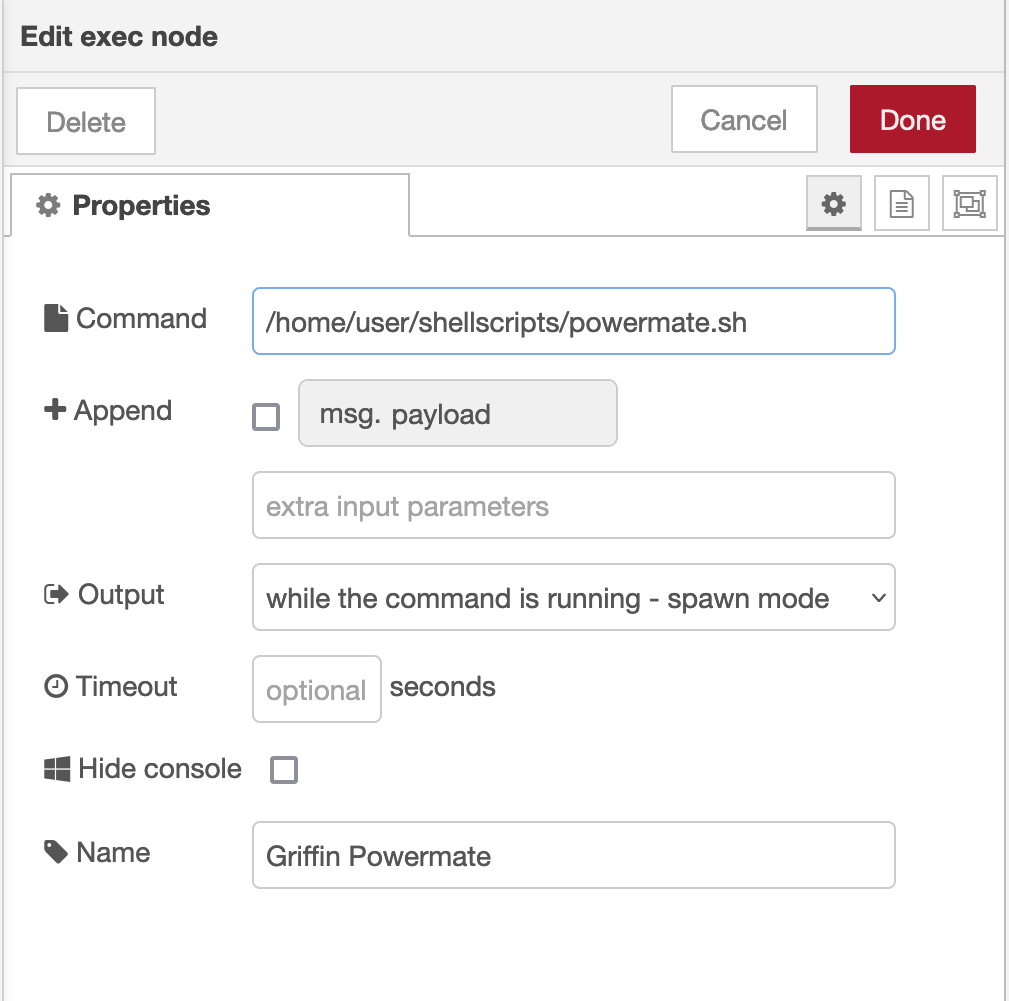
The Griffin Powermate node is a simple exec node that runs the script we created above.
M0AWS Powermate exec node
Configure the node as shown above and connect it to the inject node that’s used as a trigger. Note: Change “user” in the Command field shown above to that of your username on your Linux PC)
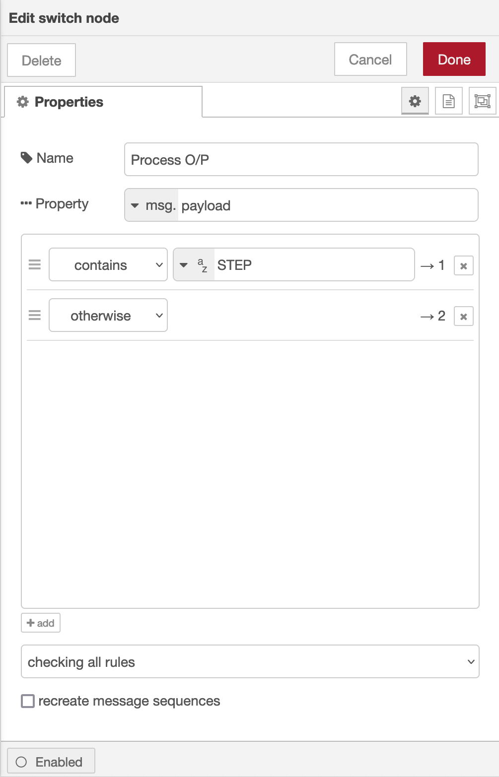
Once done create the third node in the flow, a simple switch node and configure as shown below.
Switch Node for Powermate
The switch node has two outputs, the top one is a text output that is fed into a text field to show the current step size of the Powermate device and the lower output is the numeric output that must be fed into your VFO control flow so that the VFO value is incremented/decremented by the amount output by the Powermate device.
I’ve found the Griffin Technology Powermate USB device works extremely well with Node Red and GQRX that I use for controlling the FCD SDR radio and it’s now part of my QO-100 ground station build.
M0AWS QO-100 Dashboard with Powermate Step Display at bottom
As shown above you can see the Powermate Step size at the bottom of the dashboard, this text changes each time the Powermate device is depressed and will set a step size of 1Hz, 10Hz, 100Hz, 1Khz, 10Khz in a round-robin fashion.
The next stage of the build is the 2.4Ghz transmit path. I now have all the necessary hardware and so this part of the build can finally commence.
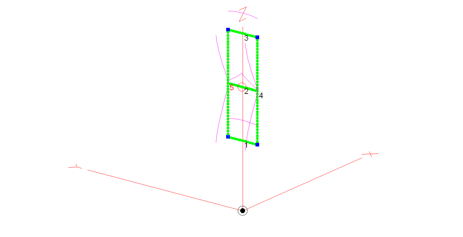
The bi-directional slot fed HF antenna isn’t mentioned very often these days for some strange reason. It’s a real shame as it is an excellent antenna that gives high gain through the loop between the frequencies of 14Mhz and 29Mhz.
M0AWS 20m – 10m Slot Fed HF Antenna
Construction of the antenna is relatively simple, 3 x 3m long horizontal wires and 2 x 9.2m long vertical wires. I’ve modelled the antenna using 20mm diameter copper tubing for the horizontal conductors and 2.5mm wire for the two vertical conductors. Using the 20mm copper tubing provides a rigid platform for the mounting of the antenna on a non-conductive mast whilst reducing weight by using 2.5mm wire for the vertical conductors. You could of course use 20mm copper tubing for all the conductors if you have a non-conductive mast that can handle the weight.
An alternative option is to hang the antenna from a high tree and secure it in position with non-conductive nylon cord. This works very well and makes it extremely easy to manually rotate.
The antenna is fed at the centre of the middle horizontal tube (conductor 2 in the image above) using one of the following methods:
Method 1 – Use a 4:1 Balun and ATU either in the radio/Radio Shack or connected directly to the Balun. Connecting a remote auto ATU to the balun directly at the feed point is the best option as you will then have a perfect 50 Ohm impedance match to the coax cable going back to the radio. (I’ve used my AH-705 and a 4:1 Balun at the feed point in the past with excellent results).
Method 2 – Connect a remote auto ATU directly to the feed point of the antenna and then 50 Ohm coax back to the radio shack. This will provide a perfect SWR match on all bands and works extremely well. (I’ve used my AH-705 remote auto ATU in this configuration as well in the past, again with excellent results and no discernible difference to method 1).
Method 3 – Feed the antenna with 450 Ohm open ladder line and use a 4:1 Balun and ATU in the radio shack to match the antenna to 50 Ohm radios. It’s important to bring the 450 Ohm ladder line away from the feed point horizontally and not vertically downwards. This will then help to protect the radiation pattern.
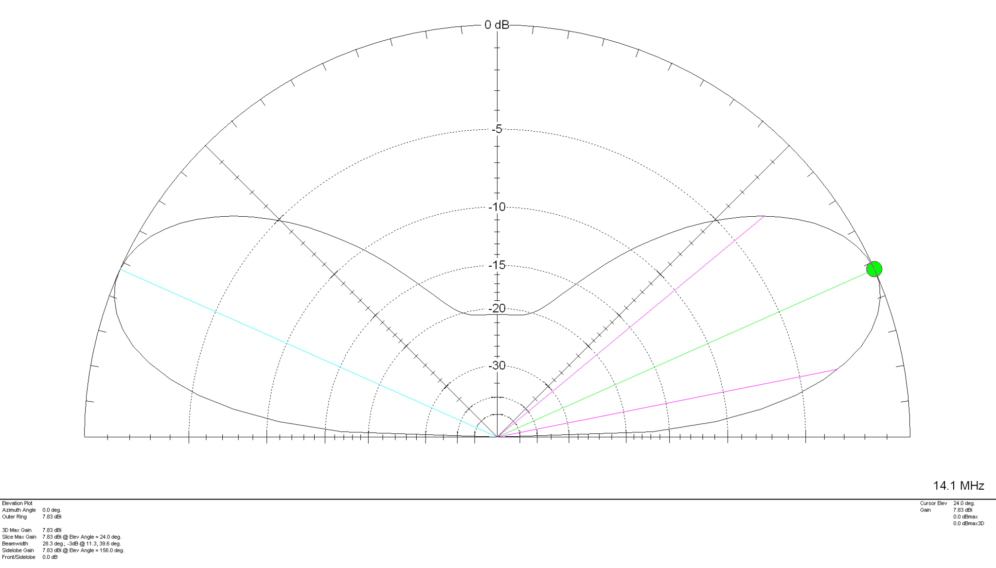
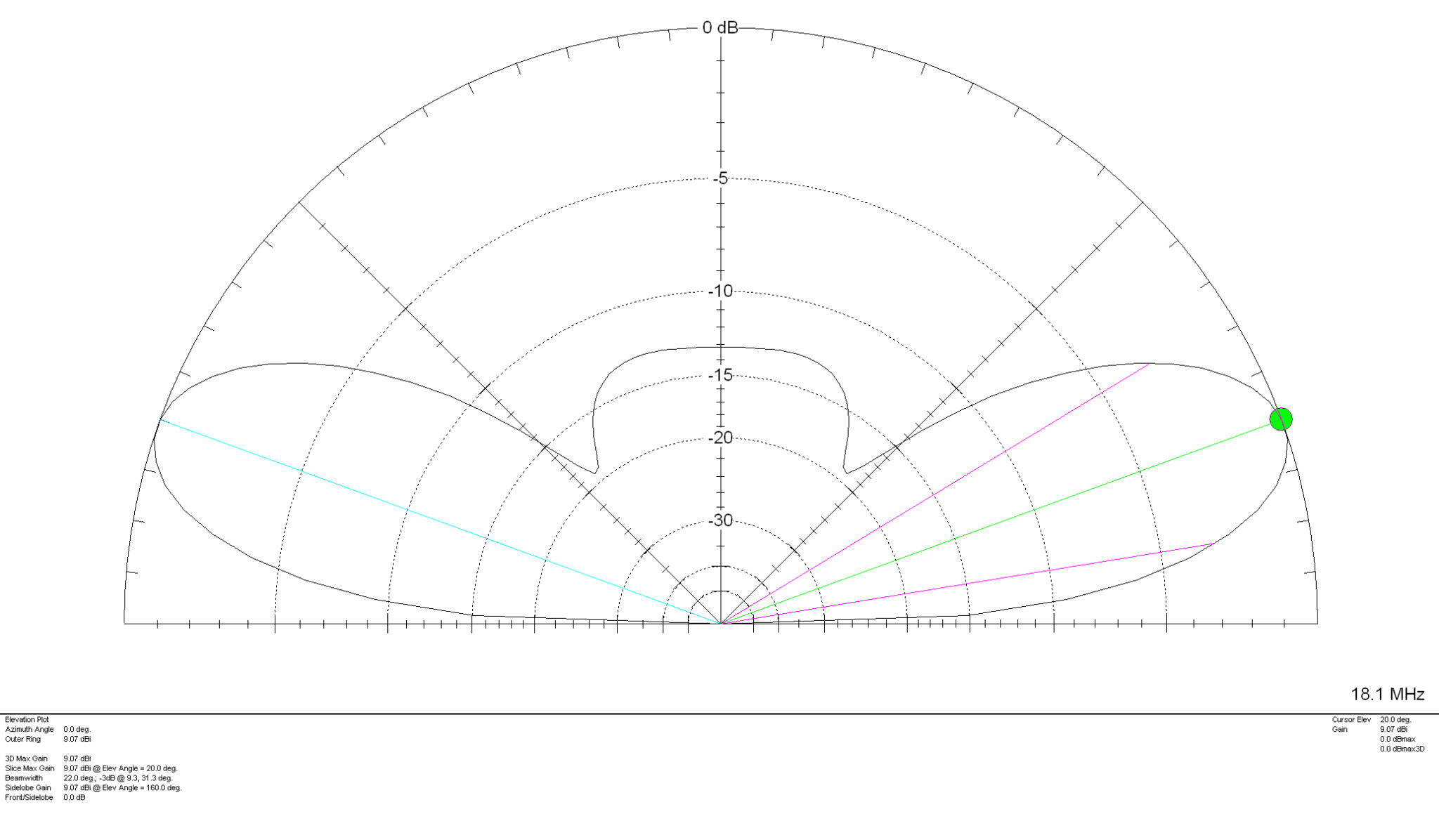
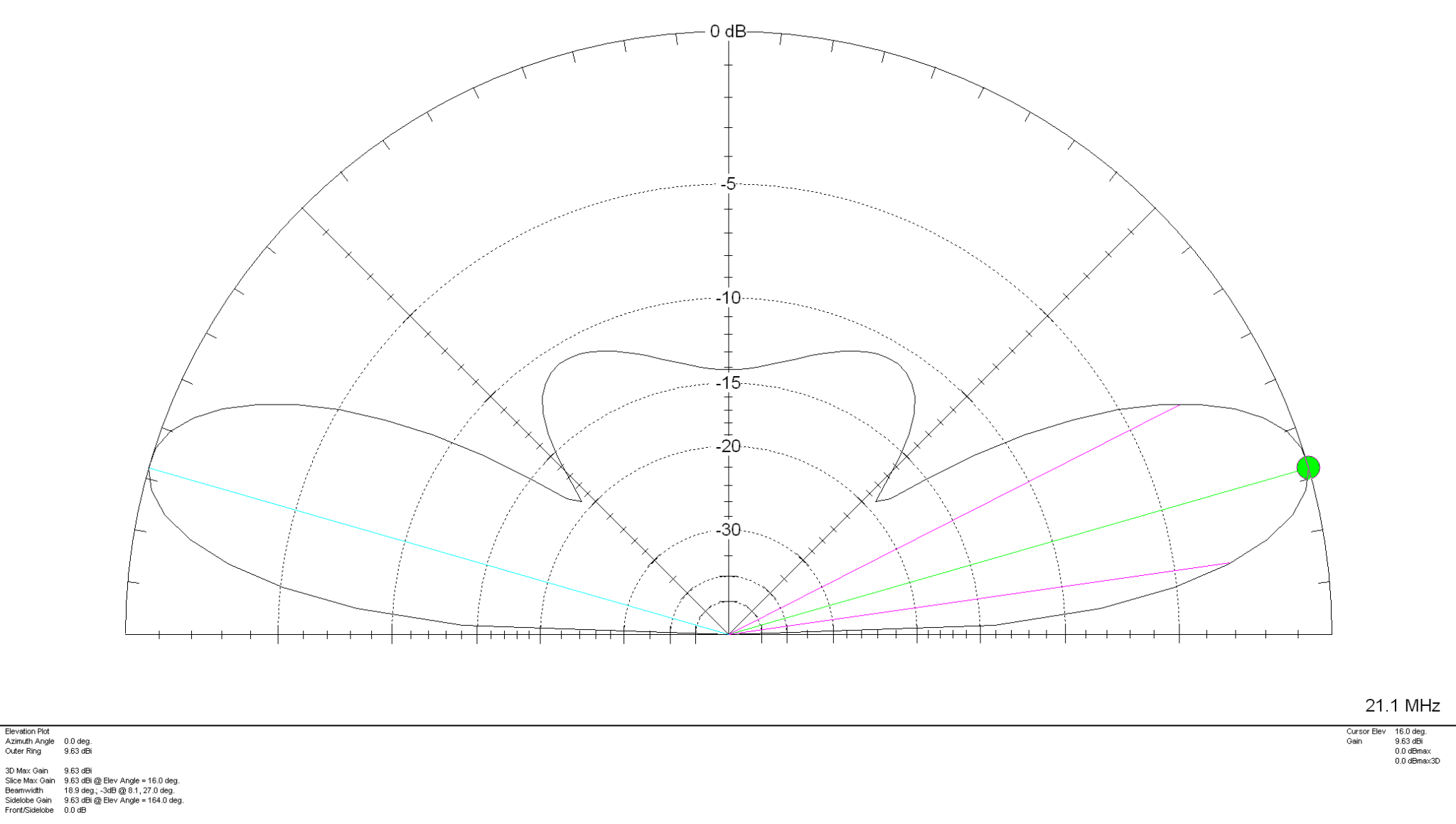
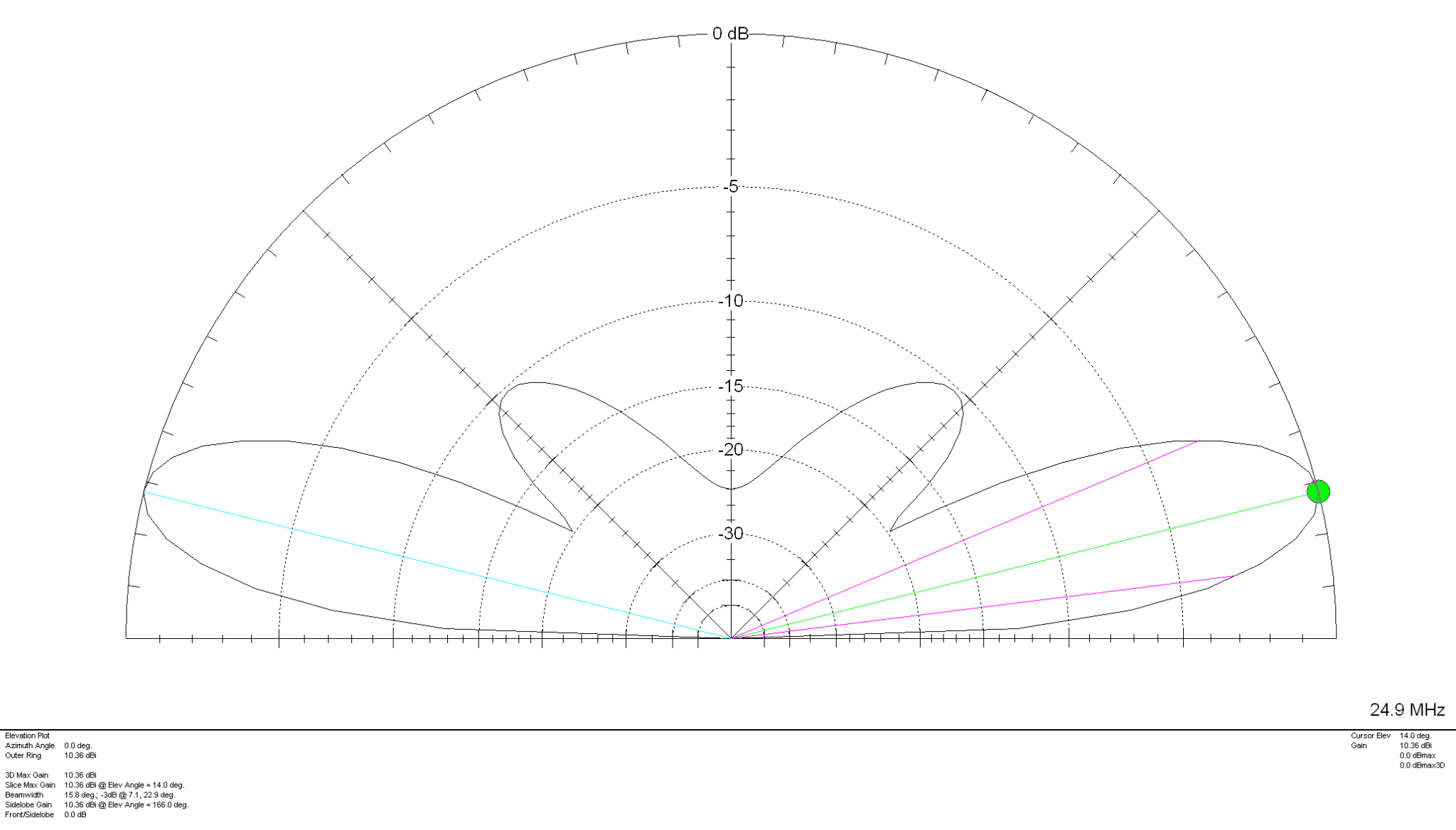
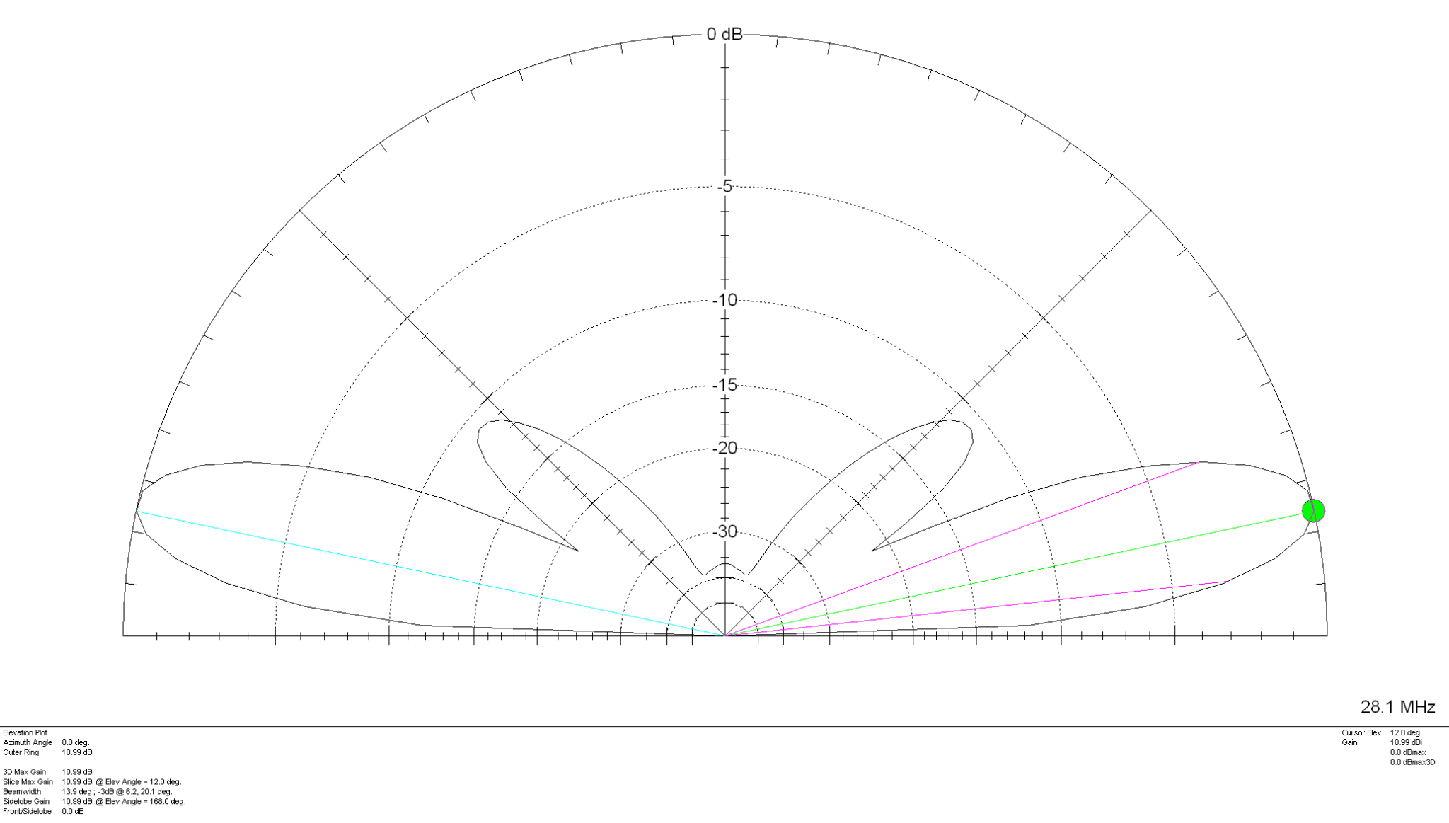
Looking at the 2D Far Field Plots this antenna provides excellent gain at relatively low radiation angles on all bands 20m – 10m making it an ideal antenna for chasing DX.
20m Band 2D Far Field Plot 17m Band 2D Far Field Plot 15m Band 2D Far Field Plot 12m Band 2D Far Field Plot 10m Band 2D Far Field Plot
The gain on each band is as follows:
20m Band – 7.83dBi at 24 Degrees 17m Band – 9.07dBi at 20 Degrees 15m Band – 9.63dBi at 16 Degrees 12m Band – 10.36dBi at 14 Degrees 10m Band – 10.99dBi at 12 Degrees
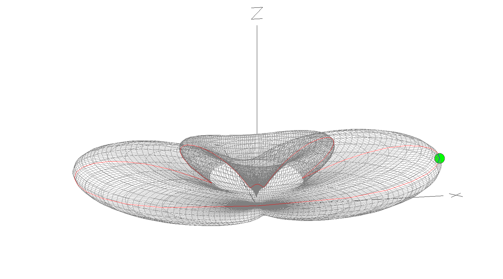
10m Band 3D Far Field Plot
The 10m Band 3D Far Field Plot above shows the typical radiation pattern for the antenna. Maximum radiation is through the loop with very little high angle radiation making it ideal for chasing DX stations. Gain increases as frequency increases however, angle of maximum radiation decreases as frequency increases improving DX capability of the antenna on the higher bands. It’s worth ensuring that the antenna is rotatable as this will then enable you to point the antenna at the DX station to maximise signal strength at the DX end. Pointing this antenna North/South makes it great for working VK/ZL over the North Pole whilst at the same time being able to work South Africa from the UK.
Summary:
Horizontal Wire Lengths: 3m @ 20mm Diameter Vertical Wire Lengths: 9.2m @ 2.5mm Diameter Modelled Height above ground at Centre (Conductor 2): 10.6m Feed Type: 4:1 Balun + ATU / Remote Auto ATU / 450 Ohm Ladder line with 4:1 Balun & ATU
Over the long bank holiday weekend I started putting together my QO-100 ground station. To start with I’ve concentrated solely on the receive path. I’ll start the transmit path once I have the receive path operational at a satisfactory level.
A few weeks ago I purchased a 1.1m off-set dish antenna and a Bullseye LNB. These have been sat in my garage waiting for the weather to improve so that I could start the build in the dry.
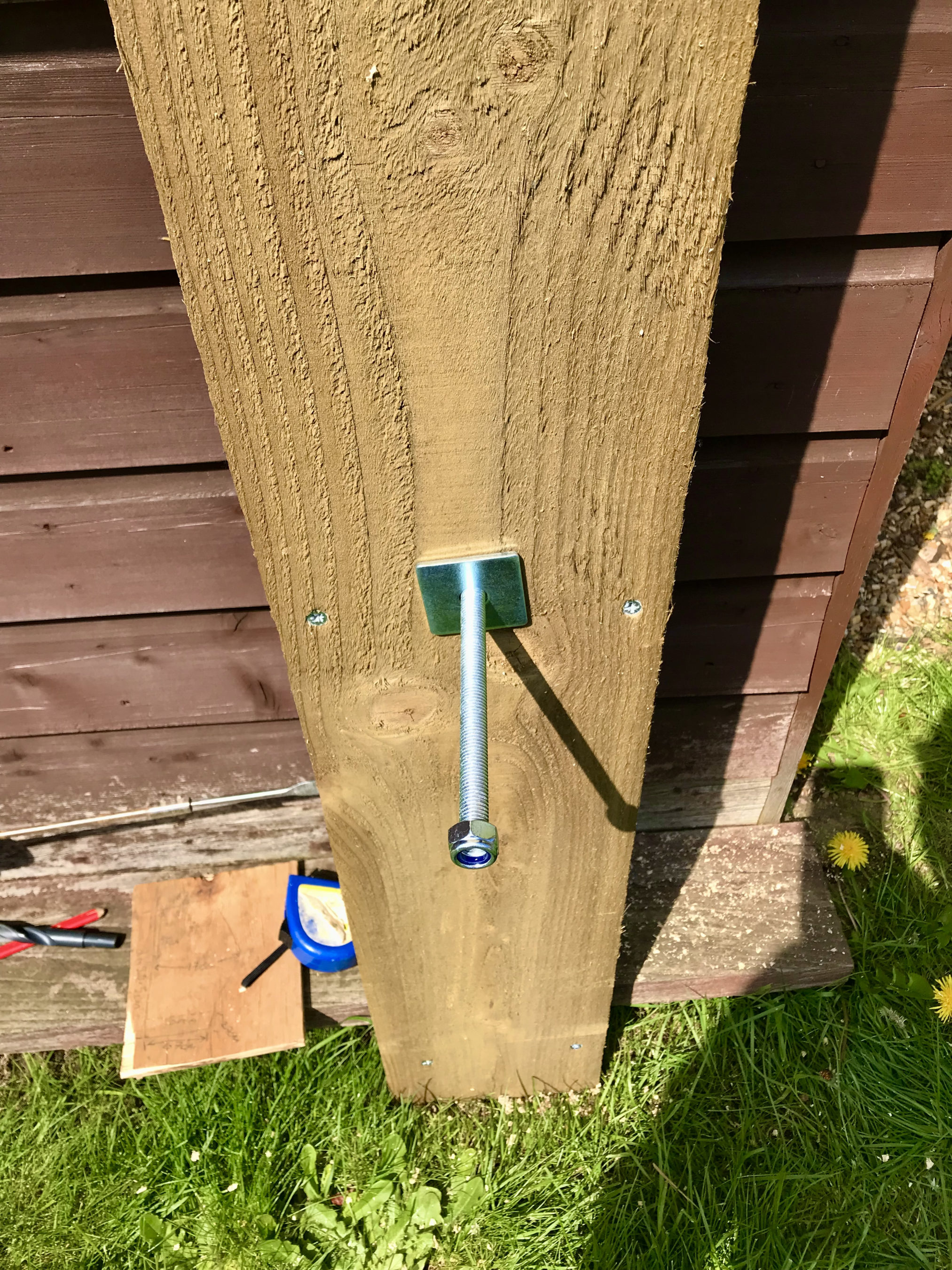
QO-100 Dish MountThrough wall bolt
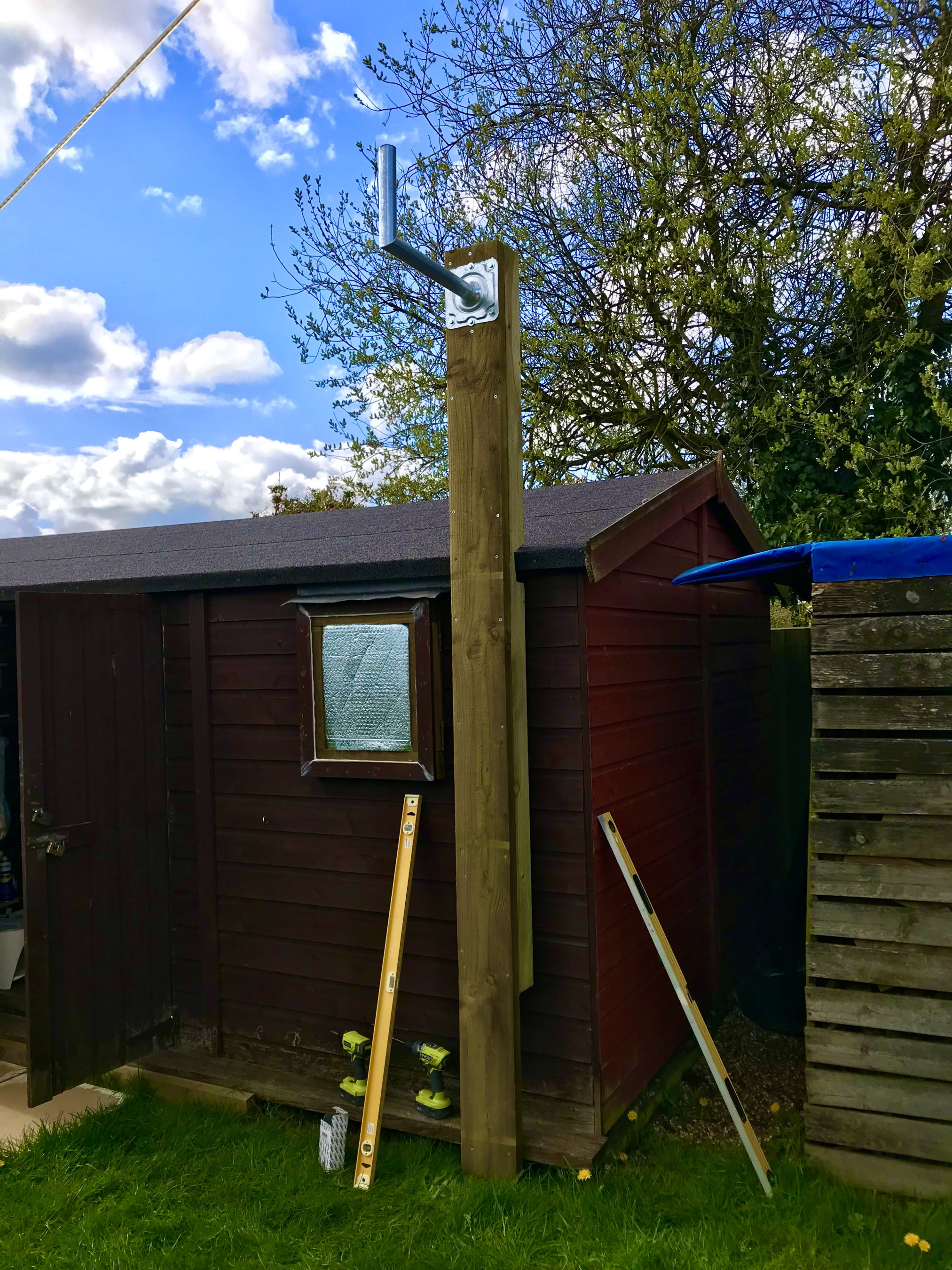
Fortunately we’ve had a mini-summer for the last 2 days and so I started work on getting the dish mount built. Using some timber from the local saw mill I made a braced 3m tall post which I screwed to the side of the cabin to provide a stable fixing platform. I used a couple of threaded bars to bolt through the walls of the cabin to ensure a solid fixing.
Next I mount the metal dish bracket to the top of the wooden post taking the total height up to around 3.2m above ground. This gives plenty of head clearance down below.
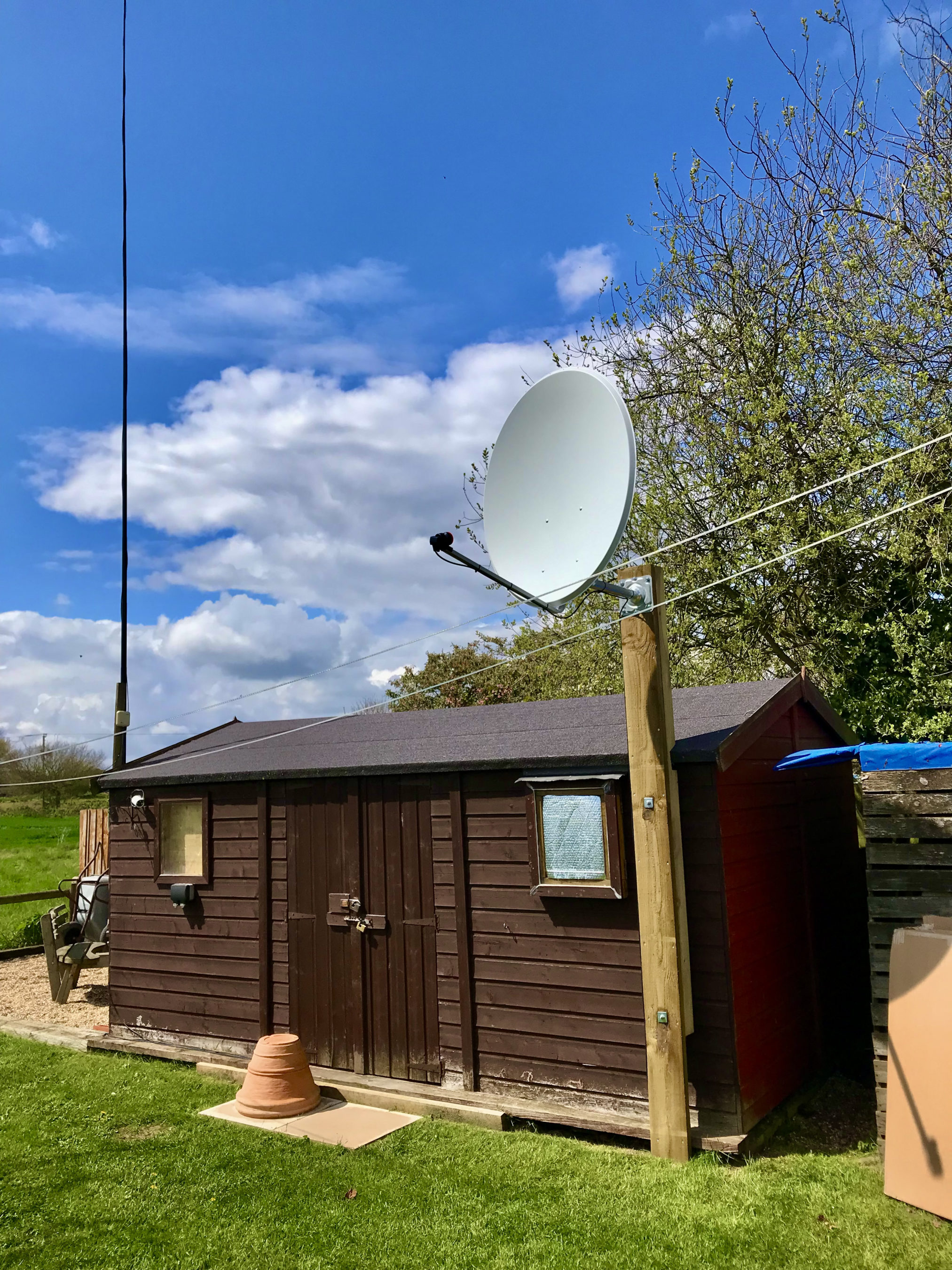
Next I assembled the dish and and attached it to the metal dish bracket at the top of the wooden post.
QO-100 1.1m dish mounted on the 3.2m AGL fixing
Attaching and cabling the Bullseye LNB was an easy job. I used some high quality coax cable that I purchase from the Satellite Superstore when I purchase the dish. I also had to set the LNB skew to -17.8 degrees. The marking on the LNB are tiny and go up in fives and so it’s pretty much impossible to get exactly -17.8 degrees so I turned it to 15 and then a tiny bit. It was as close I could get it!
Next I needed the information on where to point the dish. Fortunately there is a great web app on the BATC website where you can move a pin on a map to your location and all the information you need to align the dish is automagically calculated for you.
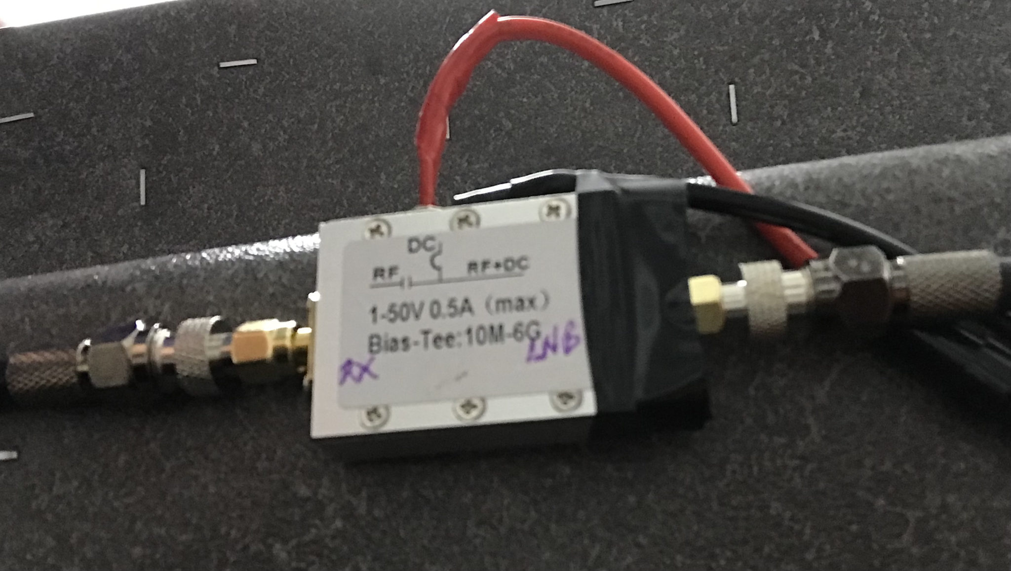
Armed with this info I set about aligning the dish. Getting it as close as possible I lightly locked off the dish and continued getting the coax in to the radio room so that I could connect it to my Funcube Dongle Pro+ (FCD) SDR receiver. Since the LNB needs a 12v DC feed I had to put inline a “Bias Tee” unit. This unit allows you to inject 12v onto the coax going up to the LNB but, stops it from coming back into the receiver. I used a Bias Tee that I purchased from Amazon with the Bullseye LNB.
Bias Tee mounted under the station desk
Connecting the coax to my Funcube Dongle Pro+ I was really pleased to see that I was receiving signals from the satellite perfectly well. I decided to take my laptop up onto the roof of the cabin and see if I could improve the reception further. To my amazement with very tiny changes in elevation and azimuth I was able to improve the QO-100 beacon signal by a further 10dB.
Being pleased with the dish alignment I started to tighten it so that it couldn’t move in the wind. Unfortunately this caused the dish to move a tiny amount which reduced the signal strength. I loosened the bolts off again and realigned the dish once more. This time when I tightened the clamps I did it a bit at a time on each bolt working my way round them so that the dish didn’t move. Doing it this way I still lost 1dB off the QO-100 beacon signal due to tiny amounts of movement but, decided I could live with the 1dB reduction.
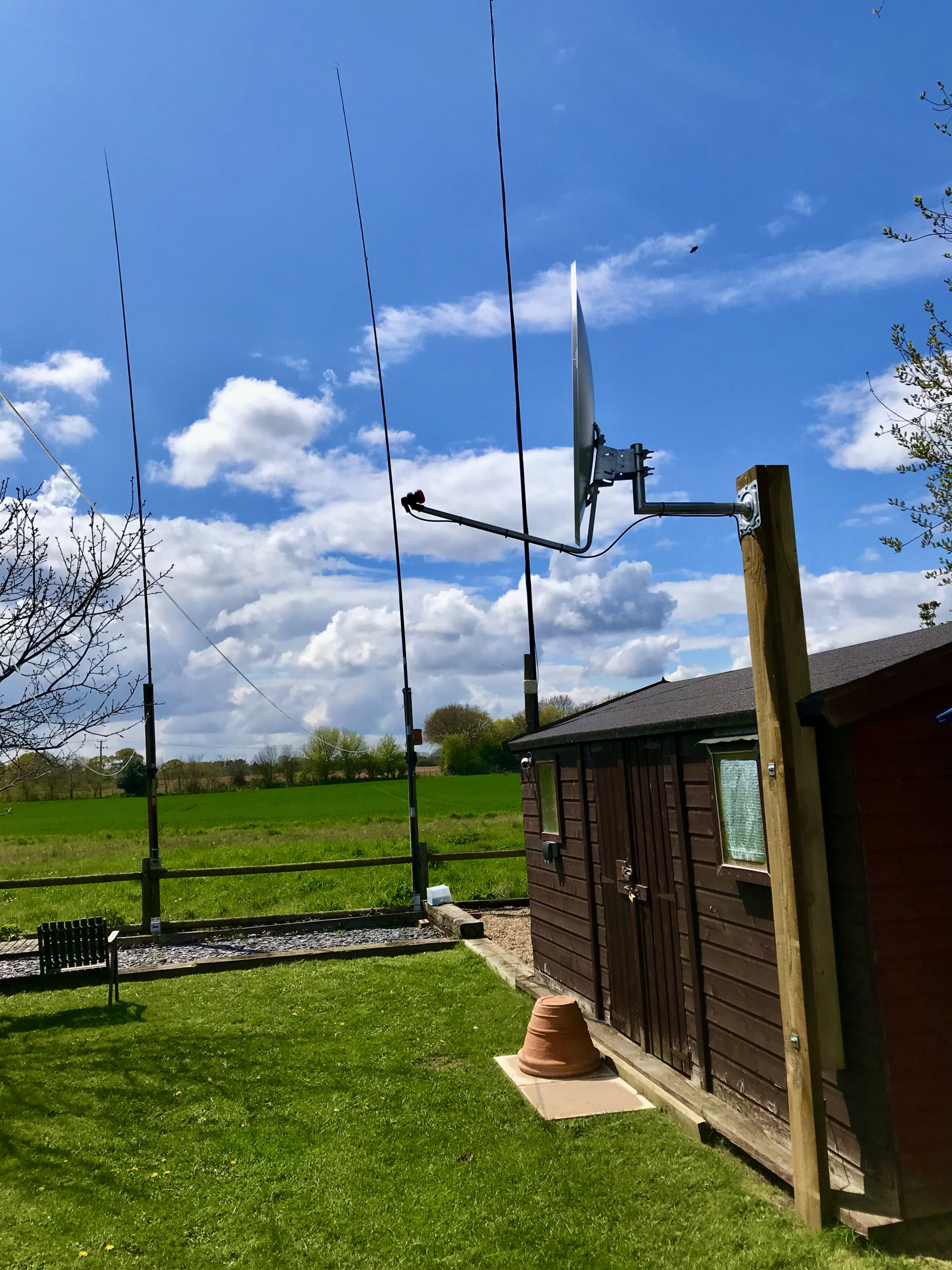
QO-100 dish successfully mounted & aligned with HF antennas in the background
Below is a very short video clip showing a German station talking on the QO-100 satellite. As you can see the signal is nice and strong and extremely clear. I did find that the output from the LNB was actually too much for the FCD SDR and so I reduced the LNA setting in GQRX to 0dB. This reduced the background noise level considerably as the receiver was no longer being overloaded and made the signals much more prevalent above the noise floor.
Short video clip showing signal clarity from the QO-100 Satellite
I’m really pleased at the performance of the receive path and have now ordered the 2.4Ghz hardware from DXPatrol and Nolle Engineering so that I can build the transmit path.
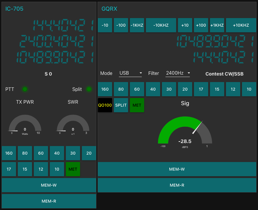
I have also made some improvements to my QO-100 Node Red Dashboard so that I can work split on the satellite using my IC-705 and FCD SDR.
QO-100 Node Red Dashboard with ‘Split’ capability
Once the 2.4Ghz hardware arrives I’ll update the blog with progress.
I’ve been chatting a lot recently on Matrix about antennas for the amateur satellites.
Since I’m currently working on building a ground station for the QO-100 satellite a group of satellite enthusiasts having been talking about the other satellites that are in orbit around this little planet of ours.
The ISS FM voice repeater on 145.990Mhz is very popular and is one of the easiest satellite stations to get into apparently. Many are using Eggbeater antennas to get an all round radiation pattern.
I’ve never looked into building or modelling such antennas and so I decided to have a go at modelling one and use it as an opportunity to see how it works.
All the modelling has been done with the antenna at 5m above ground level.
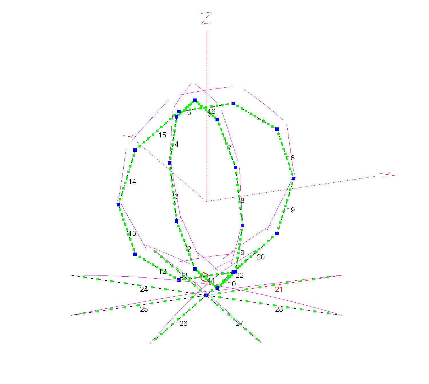
2m Band Eggbeater satellite Antenna with 8 Radials
Each loop has a circumference of 2.17m and each of the 8 radials is 0.5425m long and 5cm below the eggbeater elements. I’ve modelled the antenna using 5mm diameter conductors as this should make them resistant to wind etc. I am planning on using 5mm copper tubing for the build.
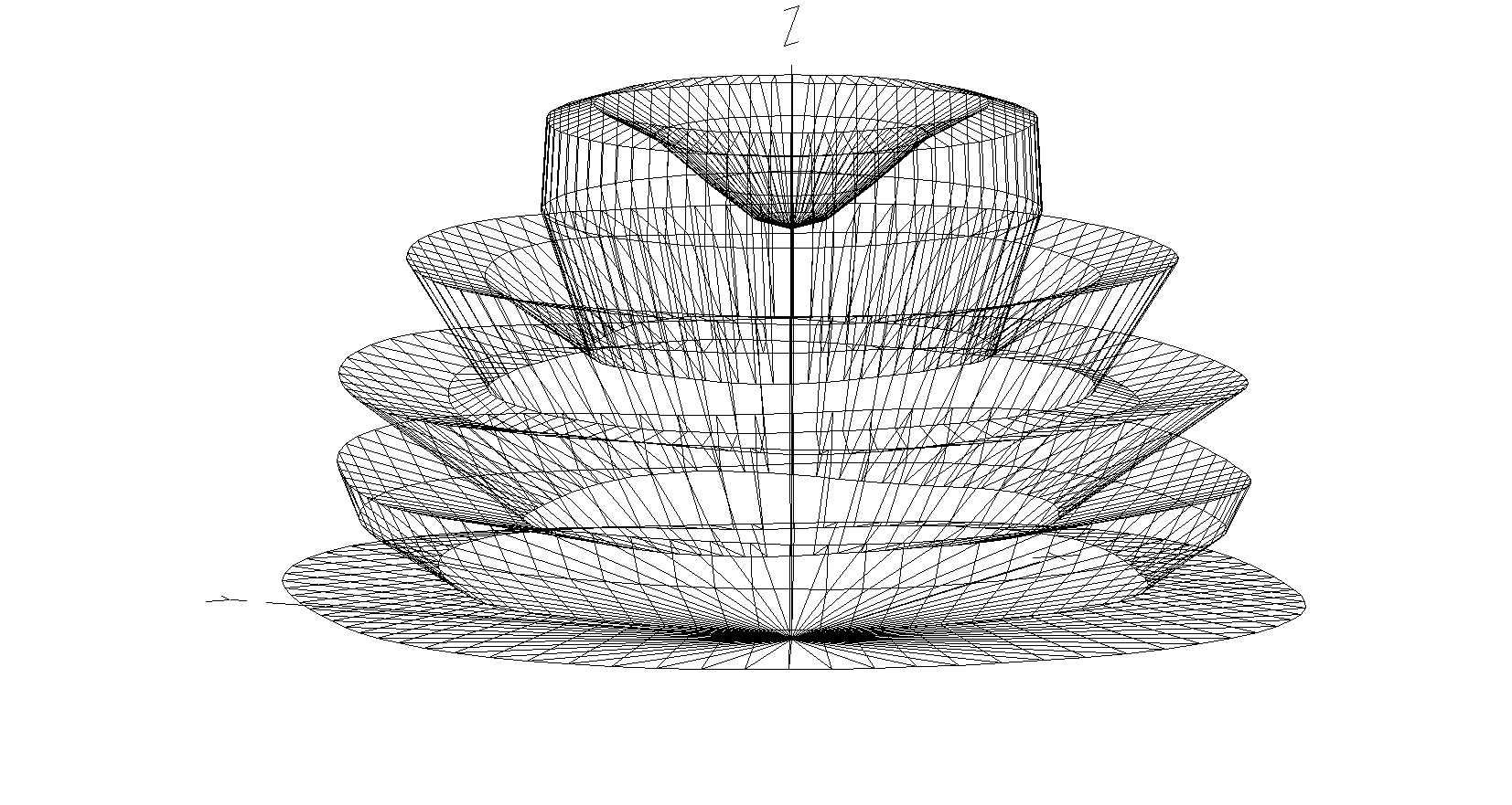
2m Band Eggbeater Satellite Antenna 3D Far Field Plot
The 3D far field plot shows a typical radiation pattern for such an antenna with a very good low angle gain for working satellites on the horizon and multiple high gain lobes as the radiation angle increases. At 5 degrees the RF is horizontally polarised, ideal for shooting directly out at the horizon. This is mainly due to the phasing of the two elements. At the higher angles the RF is vertically polarised thus giving the ability to receive both horizontal, vertical and some circular radiation at a good range of angles. There is however, a very slight null directly above the antenna and so signals to satellites directly above will be attenuated slightly compared to the other two high angle high gain lobes. This will also be the case on receive.
2m Band Eggbeater Satellite Antenna 2D Far Field Elevation Plot
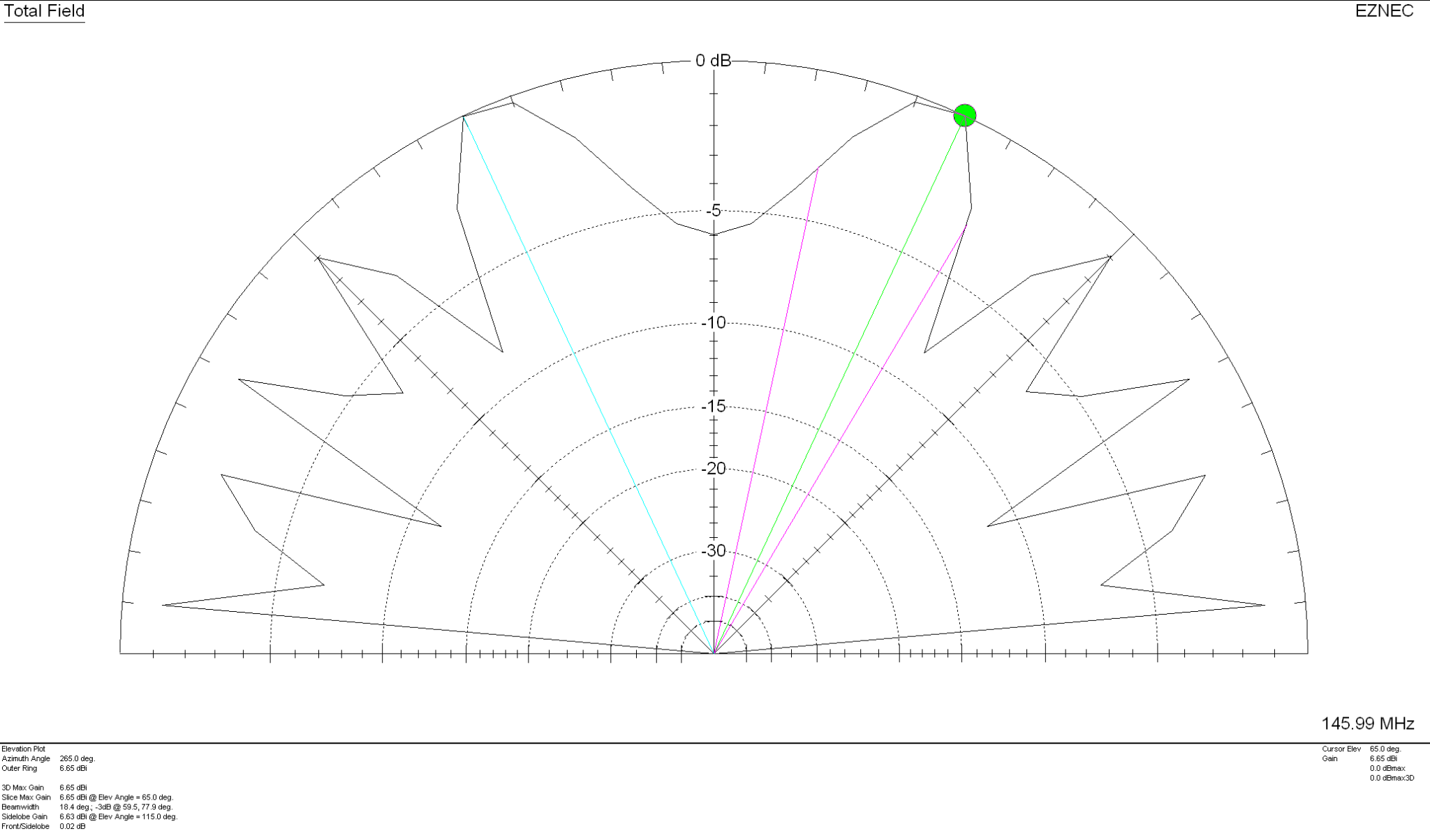
With 5.42dBi gain at 5 Deg this antenna has a real good shot at the horizon with the maximum gain of 6.65dBi being at the much higher angle of 65 Deg. Overall this antenna should work well for all satellites from the horizon up to almost directly above the antenna.
2m Band Eggbeater satellite Antenna SWR Curve
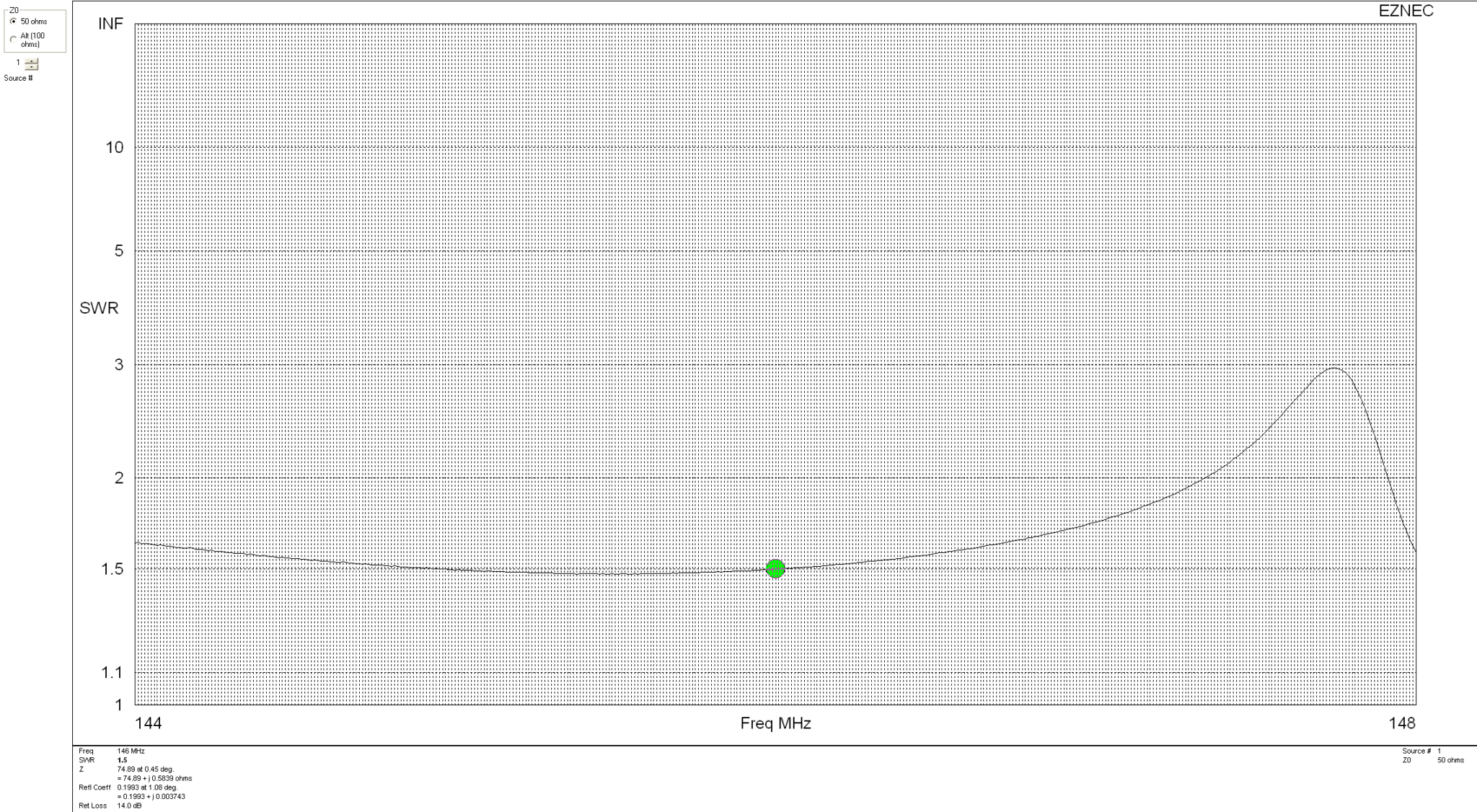
With an SWR of 1.5:1 across most of the 2m band this antenna will match perfectly to 50 Ohm coax feed. It’s really important to remember that when building this antenna the loops must be fed with a phase angle difference of exactly 90 degrees. If this isn’t accurate then the radiation pattern is affected quite drastically and spoils the overall performance of the antenna.
Details on how to create the 90 Degree phase shift between the two elements using 2 pieces of 50 Ohm coax can be found in the excellent article by ON6WG.
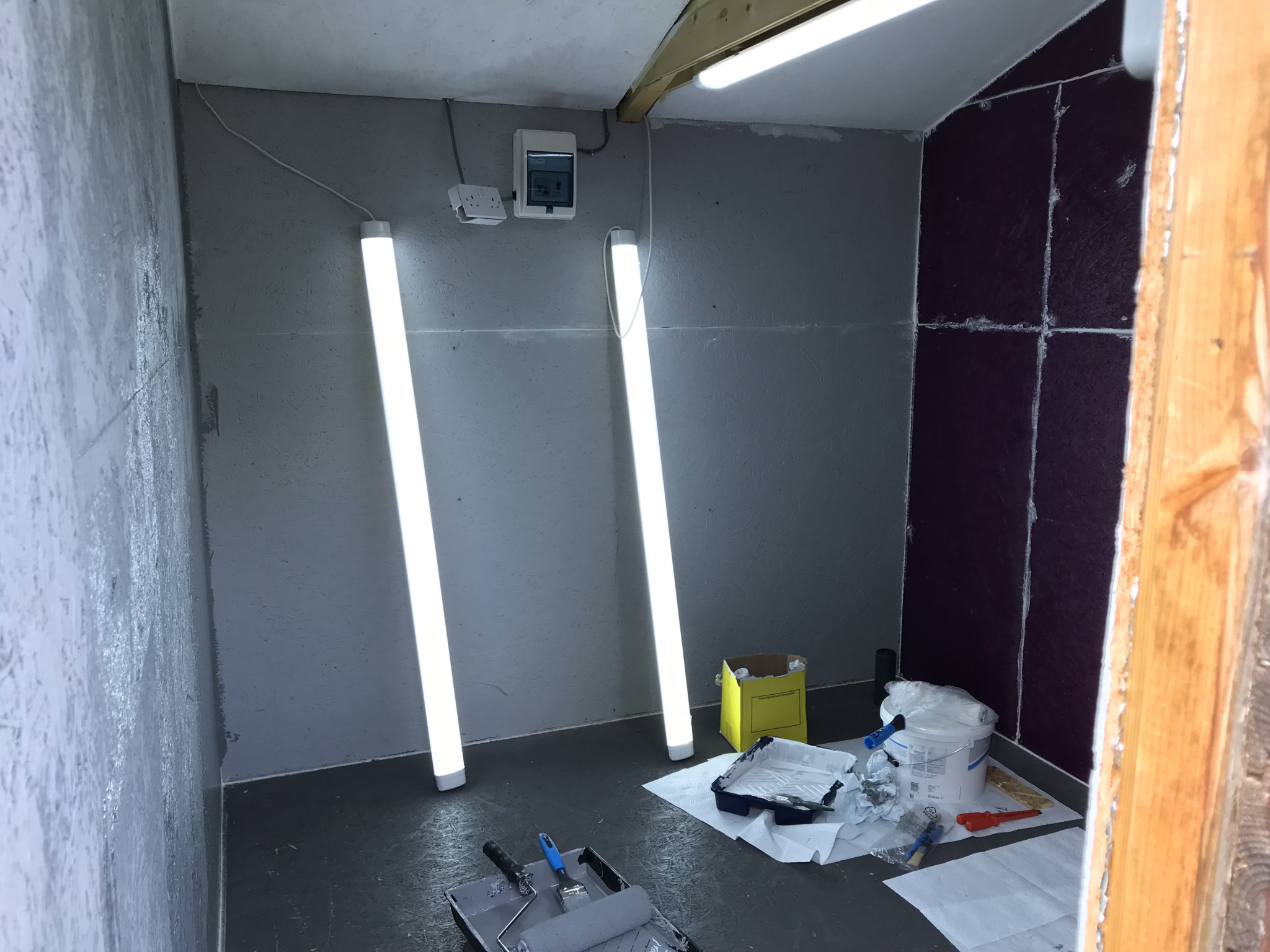
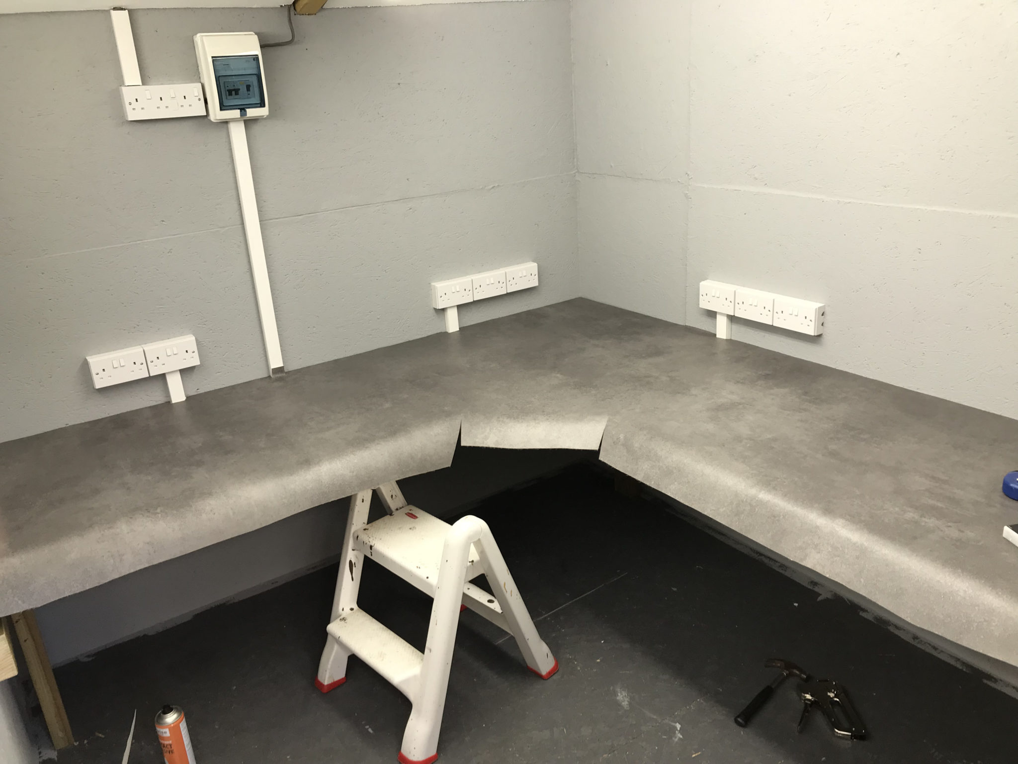
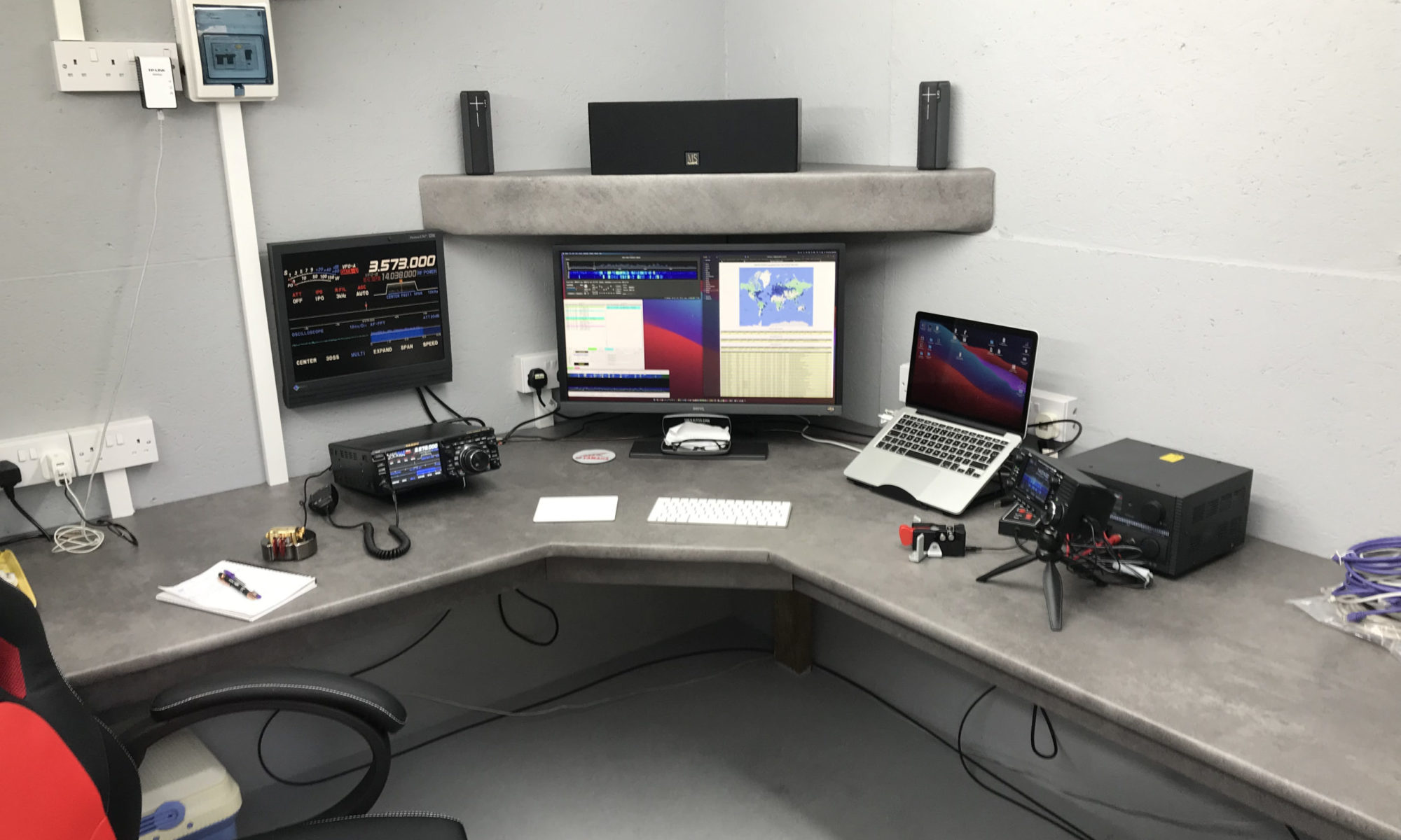
Over the last couple of weeks my wife and I have been busy converting part of my old motorcycle workshop into my new radio shack.
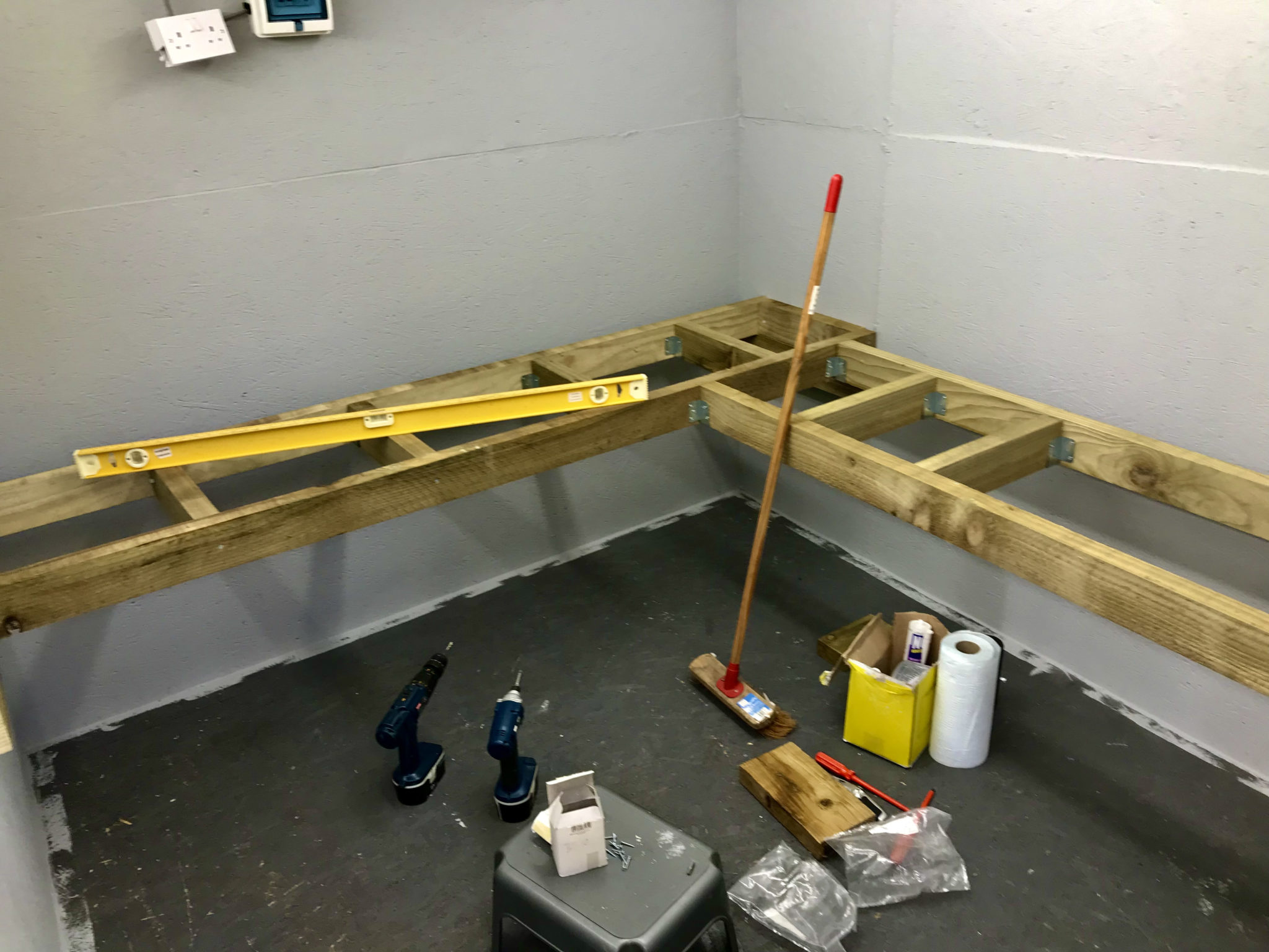
To save money we’ve custom built the desk ourselves using timber from a local supplier. I’ve done all the 240v power and lighting installation with a dedicated feed from the main distribution panel in the house.
Converting my old motorcycle workshop into my new radio shack
Custom building the desk gives us a huge advantage in that it allows us to maximise usage of the available space. Using 10mm sterling board covered with 10mm plywood makes the desk solid enough to sit on whilst fitting all the power sockets.
Bennie overseeing the project
We used a good quality padded vinyl flooring for the desk covering as it allowed us to cover the desk area in one continuous piece. It was challenging to get all the cuts in the right place and get it glued down without it moving but, with a little care and patience we got it done. We’re both really pleased with the results!
Covering the desk with good quality vinyl flooring
I’ve just got to install some cable management and shelving to complete the project but, overall I’m really pleased with the new radio shack. I’m looking forward to the winter low band DXing season!
The new M0AWS Radio Shack
More soon …
We use cookies to ensure that we give you the best experience on our website. If you continue to use this site we will assume that you are happy with it.