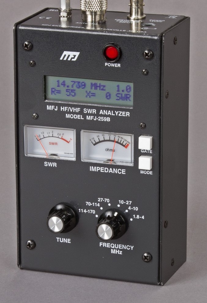
Many years ago I had an MFJ-259B antenna analyser that I used for all my HF antenna projects. It was a simple device with a couple of knobs, an LCD display and a meter but, it provided a great insight into the resonance of an antenna.
MFJ-259B Antenna Analyser
Today things have progressed somewhat and we now live in a world of Vector Network Analysers that not only display SWR but, can display a whole host of other information too.
Being an avid antenna builder I’ve wanted to buy an antenna analyser for some time but, now that I’m into the world of QO-100 satellite operations using frequencies at the dizzy heights of 2.4GHz I needed something more modern.
If you search online there are a multitude of Vector Network Analysers (VNAs) available from around the £50.00 mark right up to £1500 or more. Many of the VNAs you see on the likes of Amazon and Ebay come out of China and reading the reviews they aren’t particularly reliable or accurate.
After much research I settled on the JNCRadio VNA 3G, it gets really good reviews and is very sensibly priced. Putting a call into Gary at Martin Lynch and Sons (MLANDS) we had a long chat about various VNAs, the pros and cons of each model and the pricing structure. It was tempting to spend much more on a far more capable device however, my sensible head kicked in and decided many of the additional features on the more expensive models would never get used and so I went back to my original choice.
Gary and I also had a long chat about building a QO-100 ground station, using NodeRed to control it and how to align the dish antenna. The guys at MLANDS will soon have a satellite ground station on air and I look forward to talking to them on the QO-100 transponder.
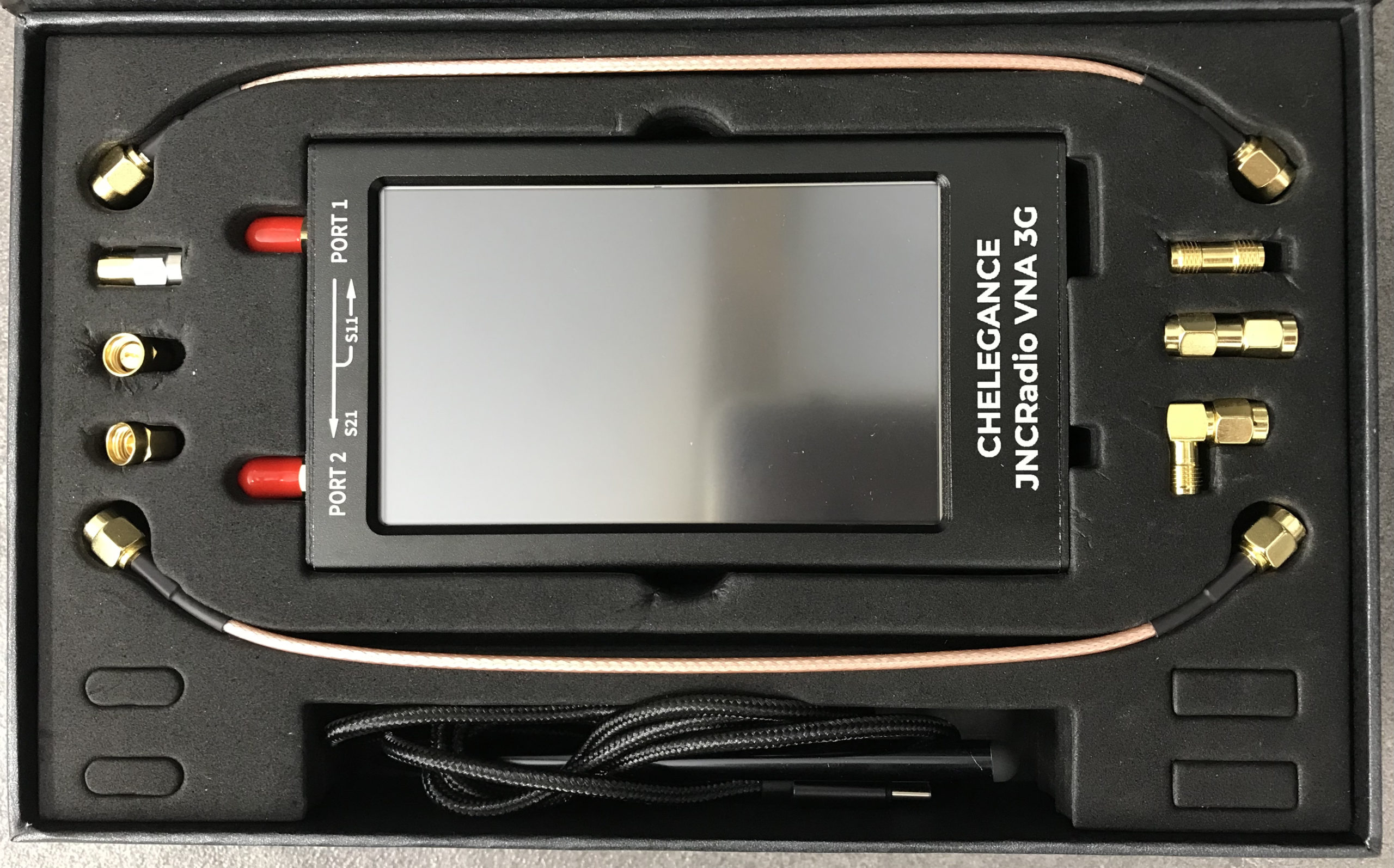
M0AWS – JNCRadio VNA 3G PackagingM0AWS – JNCRadio VNA 3G in box with connectors and cables
Initially I wanted to check the SWR of my QO-100 2.4GHz IceCone Helix antenna on my satellite ground station to ensure it was resonant at the right frequency. Hooking the VNA up to the antenna feed was simple enough using one of the cables provided with the unit and I set about configuring the start and stop stimulus frequencies (2.4GHz to 2.450GHz) for the sweep to plot the curve.
The resulting SWR curve showed that the antenna was indeed resonant at 2.4GHz with an SWR of 1.16:1. The only issue I had was that in the bright sunshine it was hard to see the display and impossible to get a photo. Setting the screen on the brightest setting didn’t improve things much either so this is something to keep in mind if you plan on using the device outside in sunny climates.
(My understanding is that the Rig Expert AA-3000 Zoom is much easier to see outside on a sunny day however, it will cost you almost £1200 for the privilege.)
A couple of days later I decided to check the SWR of my 20m band EFHW vertical antenna. I’ve known for some time that this antenna has a point of resonance below 14MHz but, the SWR was still low enough at the bottom of the 20m band to make it useable.
Hooking up the VNA I could see immediately that the point of resonance was at 13.650Mhz, well low of the 20m band and so I set about shortening the wire until the point of resonance moved up into the band.
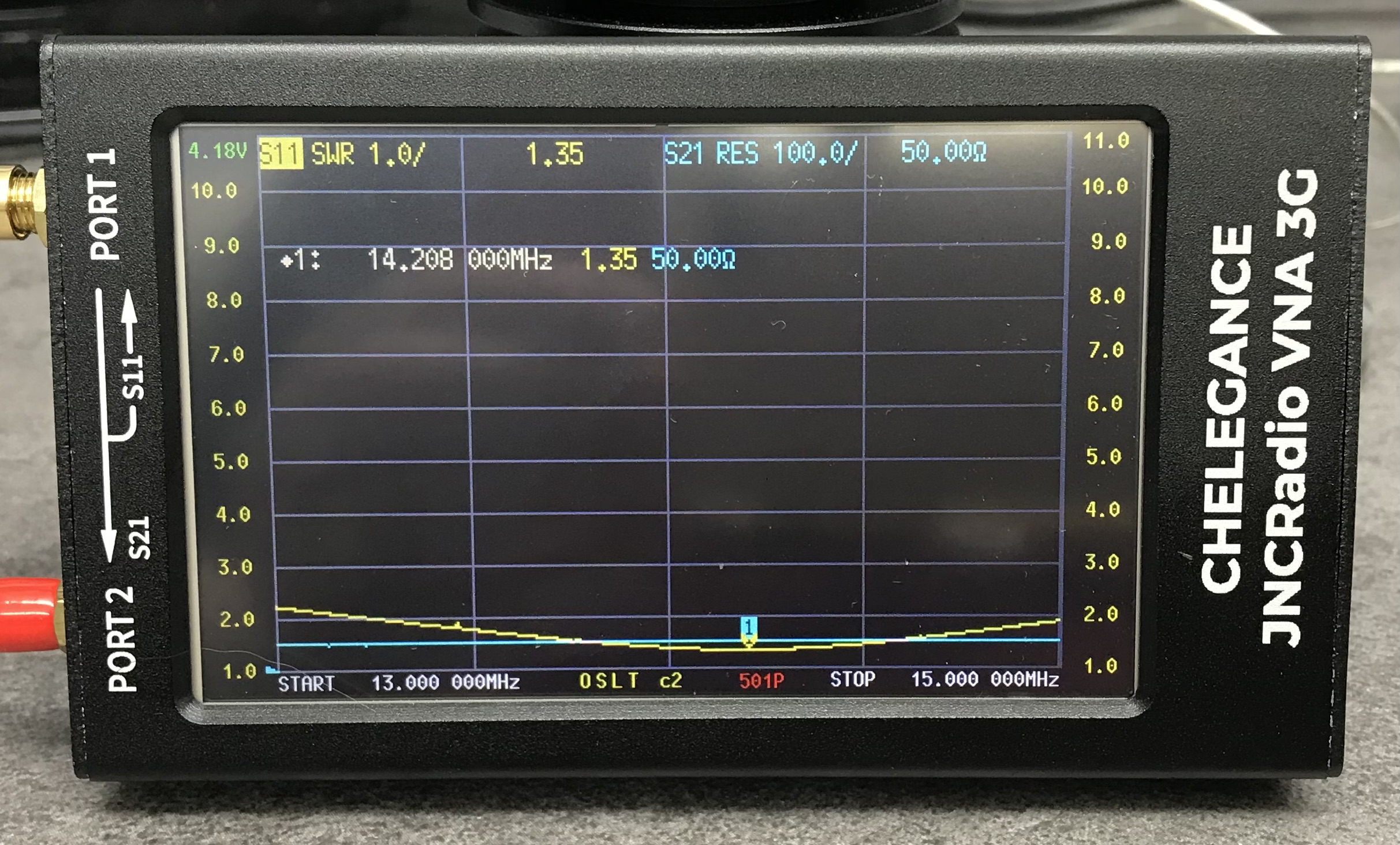
JNCRadio VNA3G showing 20m Band EFHW Resonance
With a little folding back of wire I soon had the point of resonance nicely into the 20m band with a 1.35:1 SWR at 14.208Mhz. This provides a very useable SWR across the whole band but, I decided I’d prefer the point of resonance to be slightly lower as I tend to use the antenna mainly on the CW & FT4/8 part of the band with my Icom IC-705 QRP rig.
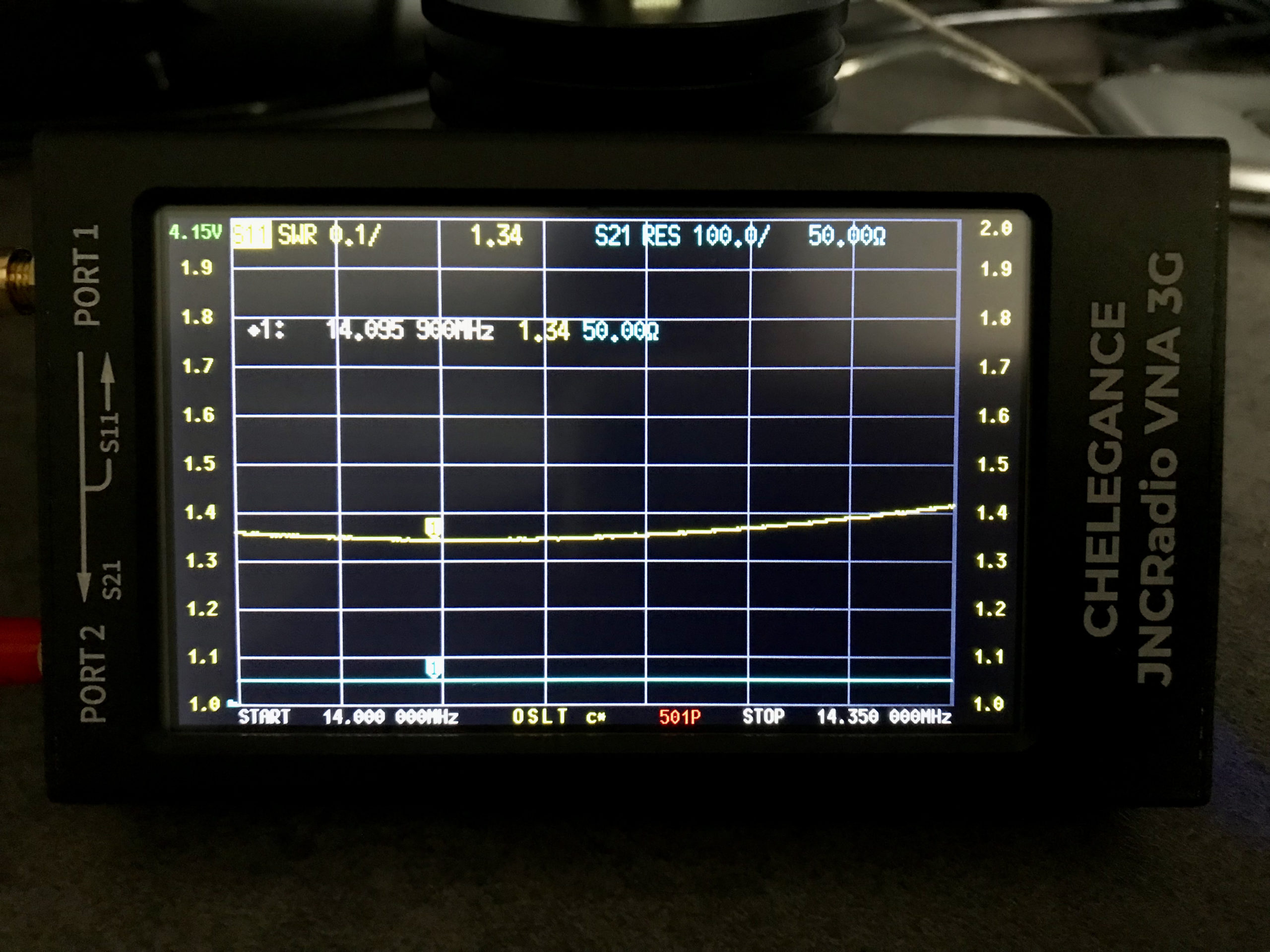
Popping out into the garden once more I lengthened the wire easily enough by reducing the fold back and brought the point of resonance down to 14.095Mhz.
JNCRadio VNA3G showing 20m Band EFHW Resonance 14Mhz to 14.35Mhz Sweep
The VNA automatically updated the display realtime to show the new point of resonance on the 4.3in colour screen. I also altered the granularity of the SWR reading on the Y axis to show a more detailed view of the curve and reduced the frequency range on the X axis so that it showed a 14Mhz to 14.35Mhz sweep. With an SWR of 1.34:1 at 14.095Mhz and a 50 Ohm impedance, the antenna is perfectly resonant where I want it.
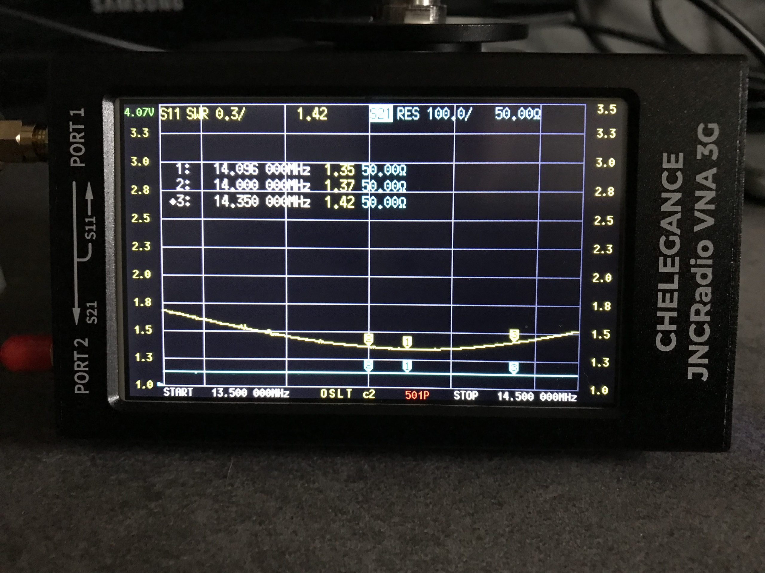
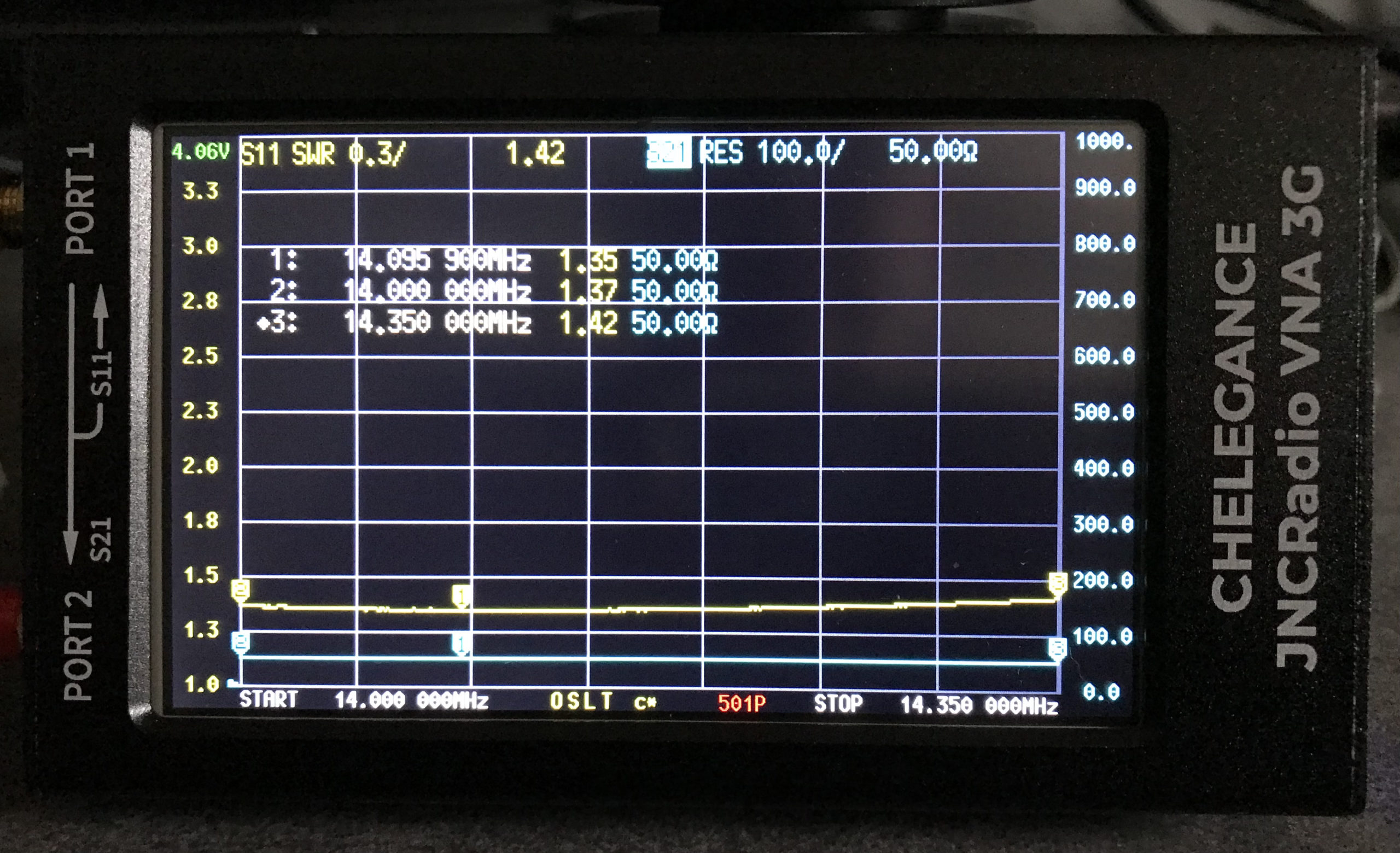
It’s interesting to note that the antenna is actually useable between 13.5Mhz and 14.5Mhz with a reasonable SWR across the entire frequency spread. Setting 3 markers on the SWR curve I could see at a glance the SWR reading at 14Mhz (Marker 2) , 14.350Mhz (Marker 3) and the minimum SWR reading at 14.095Mhz (Marker 1).
The bi-directional slot fed HF antenna isn’t mentioned very often these days for some strange reason. It’s a real shame as it is an excellent antenna that gives high gain through the loop between the frequencies of 14Mhz and 29Mhz.
M0AWS 20m – 10m Slot Fed HF Antenna
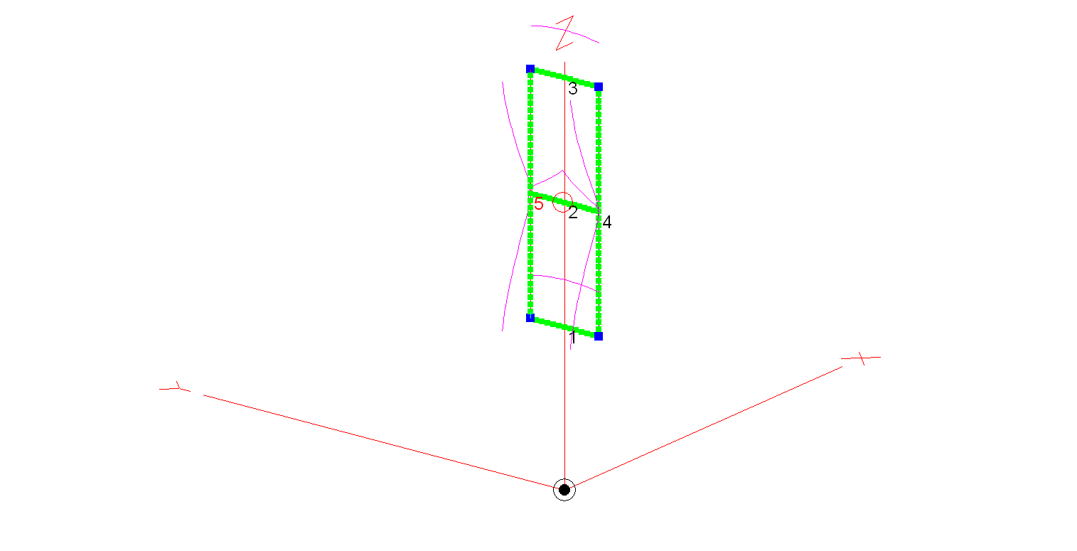
Construction of the antenna is relatively simple, 3 x 3m long horizontal wires and 2 x 9.2m long vertical wires. I’ve modelled the antenna using 20mm diameter copper tubing for the horizontal conductors and 2.5mm wire for the two vertical conductors. Using the 20mm copper tubing provides a rigid platform for the mounting of the antenna on a non-conductive mast whilst reducing weight by using 2.5mm wire for the vertical conductors. You could of course use 20mm copper tubing for all the conductors if you have a non-conductive mast that can handle the weight.
An alternative option is to hang the antenna from a high tree and secure it in position with non-conductive nylon cord. This works very well and makes it extremely easy to manually rotate.
The antenna is fed at the centre of the middle horizontal tube (conductor 2 in the image above) using one of the following methods:
Method 1 – Use a 4:1 Balun and ATU either in the radio/Radio Shack or connected directly to the Balun. Connecting a remote auto ATU to the balun directly at the feed point is the best option as you will then have a perfect 50 Ohm impedance match to the coax cable going back to the radio. (I’ve used my AH-705 and a 4:1 Balun at the feed point in the past with excellent results).
Method 2 – Connect a remote auto ATU directly to the feed point of the antenna and then 50 Ohm coax back to the radio shack. This will provide a perfect SWR match on all bands and works extremely well. (I’ve used my AH-705 remote auto ATU in this configuration as well in the past, again with excellent results and no discernible difference to method 1).
Method 3 – Feed the antenna with 450 Ohm open ladder line and use a 4:1 Balun and ATU in the radio shack to match the antenna to 50 Ohm radios. It’s important to bring the 450 Ohm ladder line away from the feed point horizontally and not vertically downwards. This will then help to protect the radiation pattern.
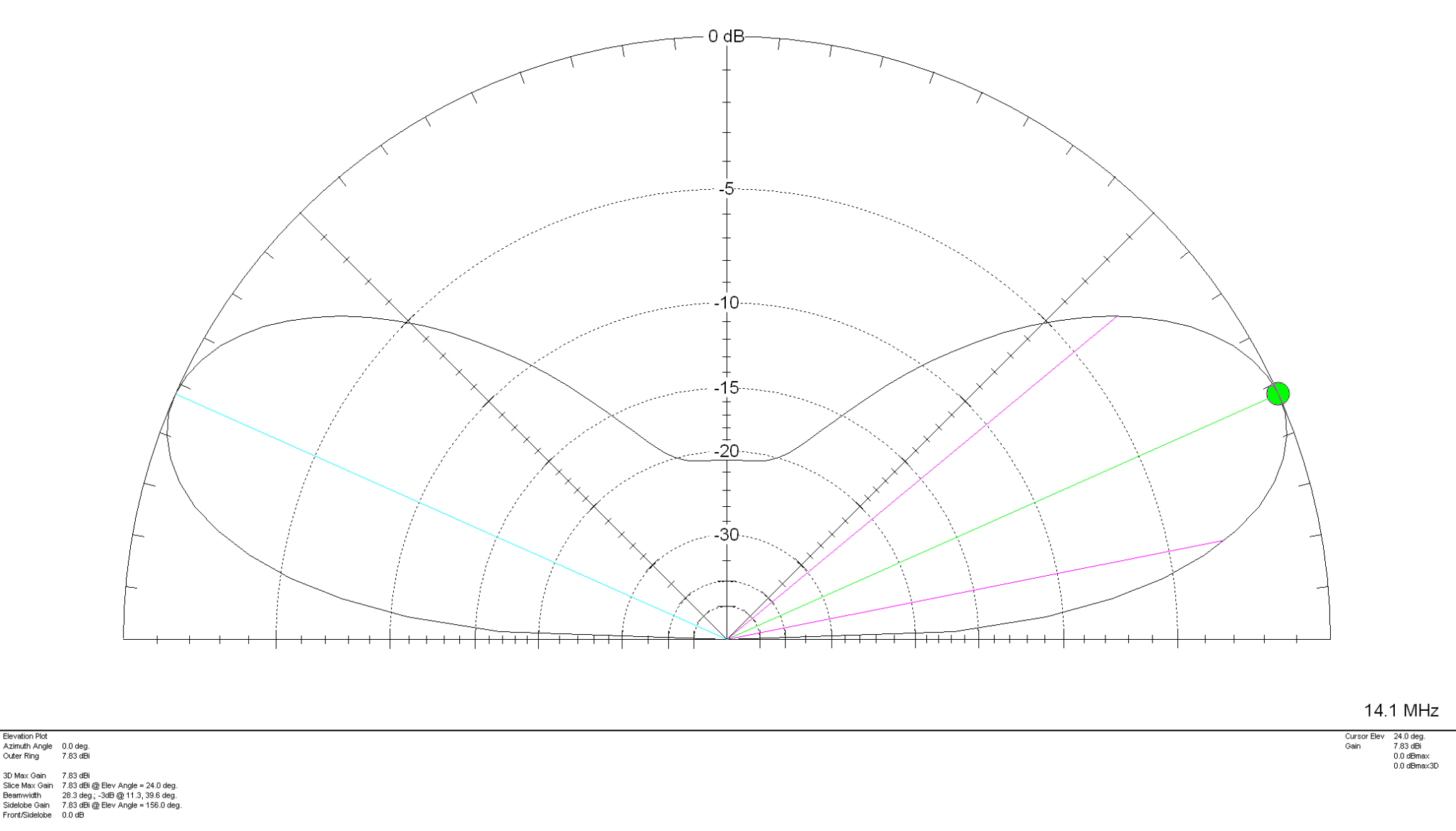
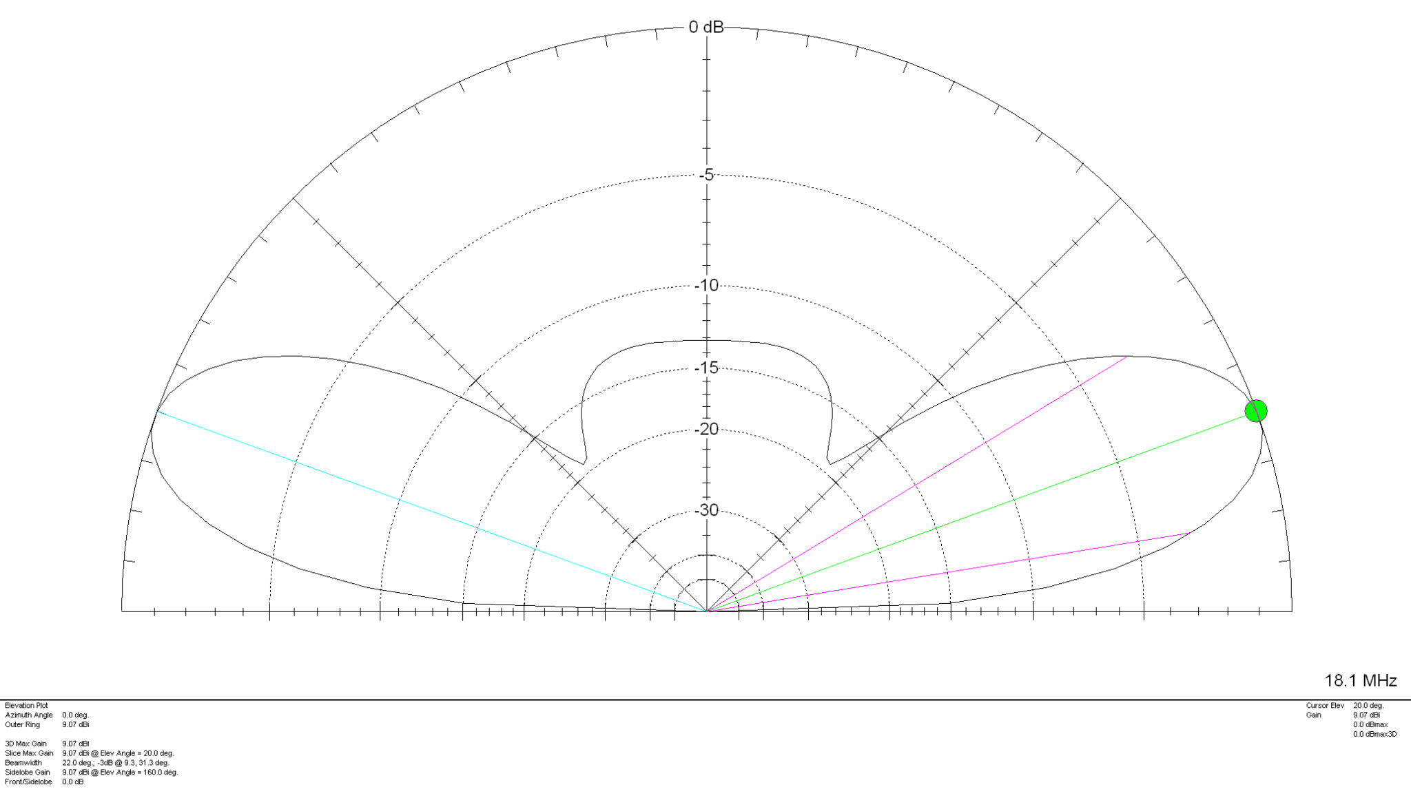
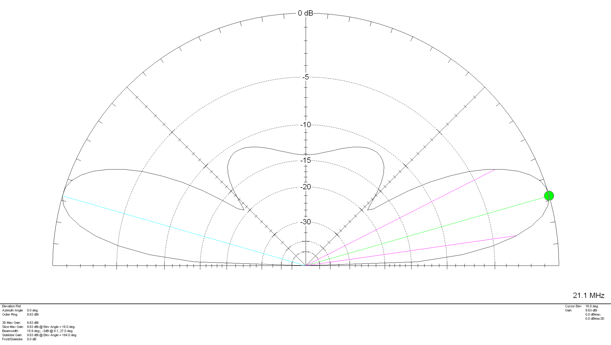
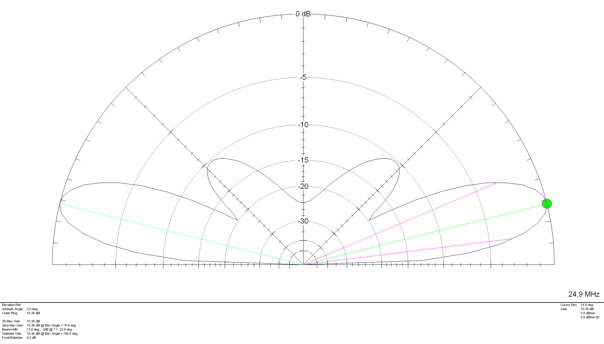
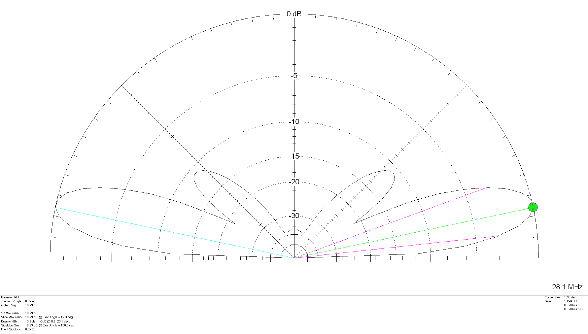
Looking at the 2D Far Field Plots this antenna provides excellent gain at relatively low radiation angles on all bands 20m – 10m making it an ideal antenna for chasing DX.
20m Band 2D Far Field Plot 17m Band 2D Far Field Plot 15m Band 2D Far Field Plot 12m Band 2D Far Field Plot 10m Band 2D Far Field Plot
The gain on each band is as follows:
20m Band – 7.83dBi at 24 Degrees 17m Band – 9.07dBi at 20 Degrees 15m Band – 9.63dBi at 16 Degrees 12m Band – 10.36dBi at 14 Degrees 10m Band – 10.99dBi at 12 Degrees
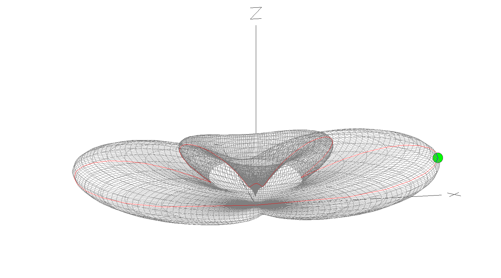
10m Band 3D Far Field Plot
The 10m Band 3D Far Field Plot above shows the typical radiation pattern for the antenna. Maximum radiation is through the loop with very little high angle radiation making it ideal for chasing DX stations. Gain increases as frequency increases however, angle of maximum radiation decreases as frequency increases improving DX capability of the antenna on the higher bands. It’s worth ensuring that the antenna is rotatable as this will then enable you to point the antenna at the DX station to maximise signal strength at the DX end. Pointing this antenna North/South makes it great for working VK/ZL over the North Pole whilst at the same time being able to work South Africa from the UK.
Summary:
Horizontal Wire Lengths: 3m @ 20mm Diameter Vertical Wire Lengths: 9.2m @ 2.5mm Diameter Modelled Height above ground at Centre (Conductor 2): 10.6m Feed Type: 4:1 Balun + ATU / Remote Auto ATU / 450 Ohm Ladder line with 4:1 Balun & ATU
Over the years I’ve built many multi band vertical HF antennas including multi-element quarter wave verticals like the DXCommander configuration, multiple end fed vertical dipoles all on the same pole and a host of other configurations. As with all multi band antennas there’s always a compromise, on some bands it performs well and on others it doesn’t, it’s the nature of the beast.
For some time now I’ve been using a multi band vertical antenna that has over the last year performed incredibly well on all bands from 80m to 10m. Don’t get me wrong, it’s not perfect however, it has out performed every other multi band HF vertical I’ve tried to date even though it’s by far the simplest antenna design and according to the antenna modelling software I have it shouldn’t be as good as it is.
So what is this magical multi band HF vertical I speak of? Well it’s nothing more than a piece of wire 13.4m long taped up a 12.4m vertical Spiderpole with 1m of wire tucked down into the top of the Spiderpole.
Obviously this is not going to be resonant on any band without some sort of impedance matching circuit at the bottom of the wire. Originally this antenna was my end fed half wave vertical antenna for the 30m band that was fed via a 49:1 Unun. This antenna worked incredibly well on the 30m band allowing me to work DX globally with ease but, it was a single band antenna and I wanted a multi band solution.
I decided to remove the 49:1 Unun and replace it with a home brew LC circuit made up of a coil made from 5mm copper tubing and a large air spaced variable capacitor I had laying around from an old ATU project I built many moons ago.
This simple LC arrangement at the bottom of the wire worked incredibly well and tuned the wire from 80m to 10m with a perfect SWR on each band using nothing more than a ground rod and 4 x 12m radials. Performance was surprisingly good on all bands 80-10m giving me the ability to get some DX stations that I’ve never been able to hit before. The only drawback to this solution was the fact that I had to go out and manually tune the antenna every time I wanted to change band. Not so much of a problem in the summer but, in the winter in the pouring rain and howling wind it’s no fun at all. (I resolve this issue further down in the article!)
Multi Band Vertical HF Antenna using a 12.4m Heavy duty Spiderpole at the end of the garden
Performance on the HF bands is incredibly impressive with this antenna. Modelling it on EzNEC software it shouldn’t be that great on bands above 20m however, it seems to defy the modelling software as it performs amazingly well on 17m, 15m and 12m, better than any other vertical antenna I’ve made for those bands. How this can be I do not know, normally my antenna builds match closely what the modelling software shows but, in this instance it doesn’t and I’ve really no idea why.
Multi Band Vertical HF Antenna showing loop at top and wire tucked down into pole
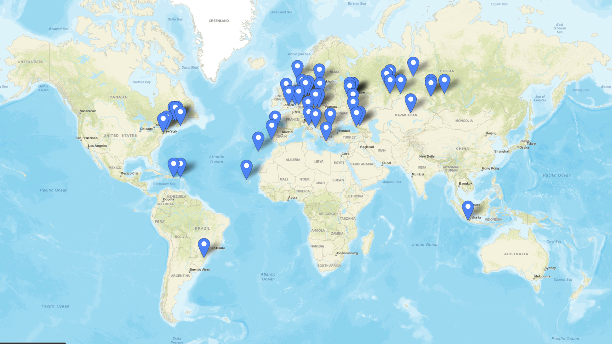
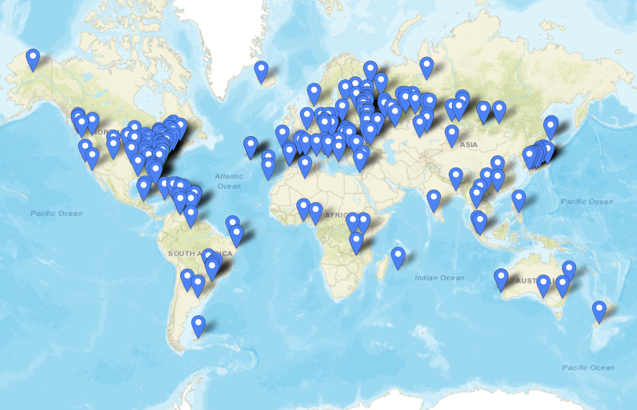
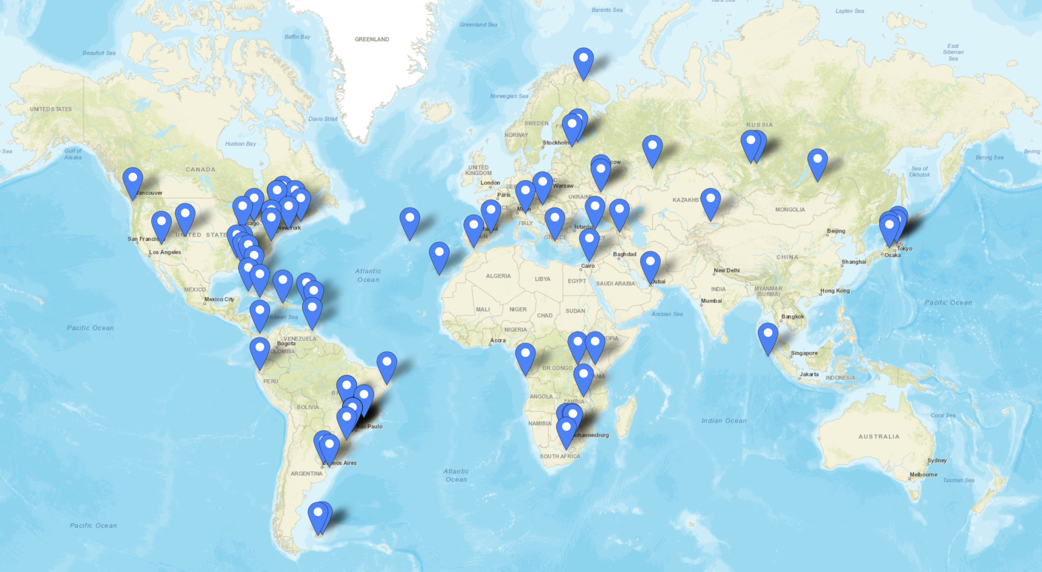
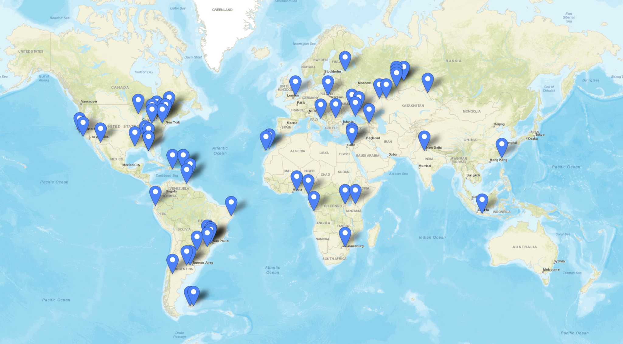
Always wanting to put things into perspective here’s some details of the contacts I’ve made on each band showing how well this antenna has performed over the last year or so.
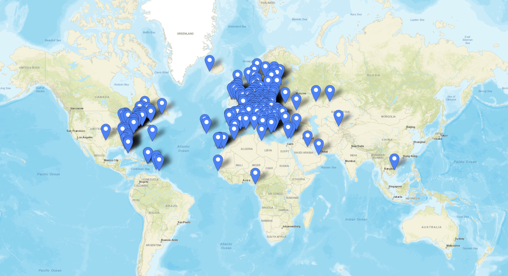
Firstly the 80m band, I’ve not used this band much over the winter months as I’ve got into the higher bands however, the map below shows all the stations worked on 80m using this antenna.
Stations worked on the 80m band from the M0AWS QTH
There are 51 contacts in total, not a big number by any means however, there are some good distances made with contacts into North America, South America and Indonesia. I’m sure I could had done better if I’d spent more time on this band, something to aim for next winter perhaps.
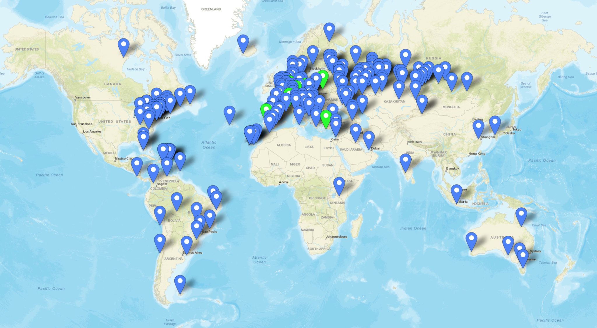
Next is the 60m band, a band I really like and have enjoyed over the winter months. The antenna performs incredibly well on this band even though we have very limited access to 60m here in the UK. With 288 contacts in the log with a good spread of distances I’m really pleased with how this antenna performs on this band.
Stations worked on the 60m band from the M0AWS QTH
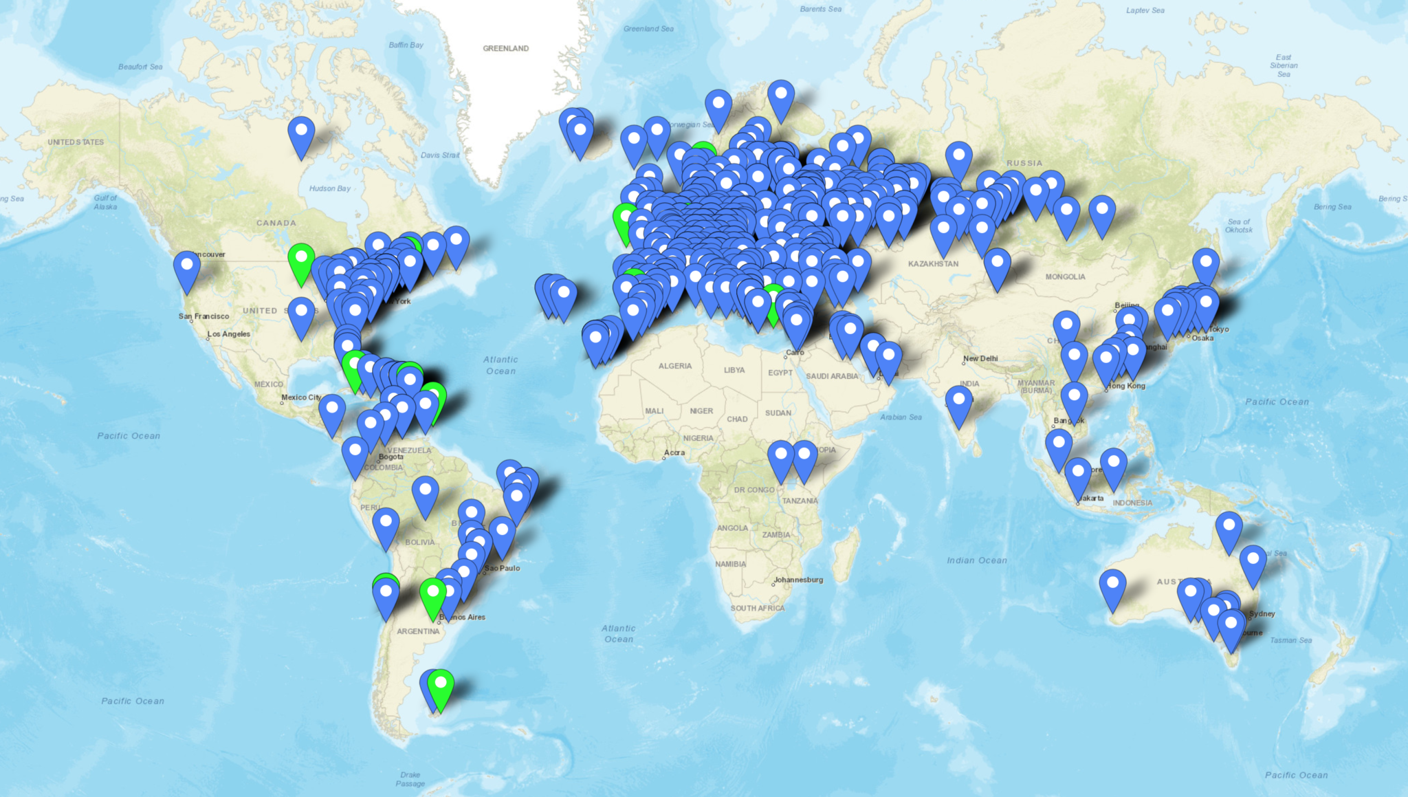
Moving up in frequency the 40m band is the next one on the list, this is a great band and one that I’ve loved for many years. I’ve spent countless hours on CW on this band in the past and worked some great DX. The performance of this antenna on the 40m band is excellent, if I can hear the DX normally I can work them regardless of where in the world they are located. With 226 contacts in the log spread globally over the winter here in the northern hemisphere I have no complaints about performance of this antenna on the 40m band.
Stations worked on the 40m band from the M0AWS QTH
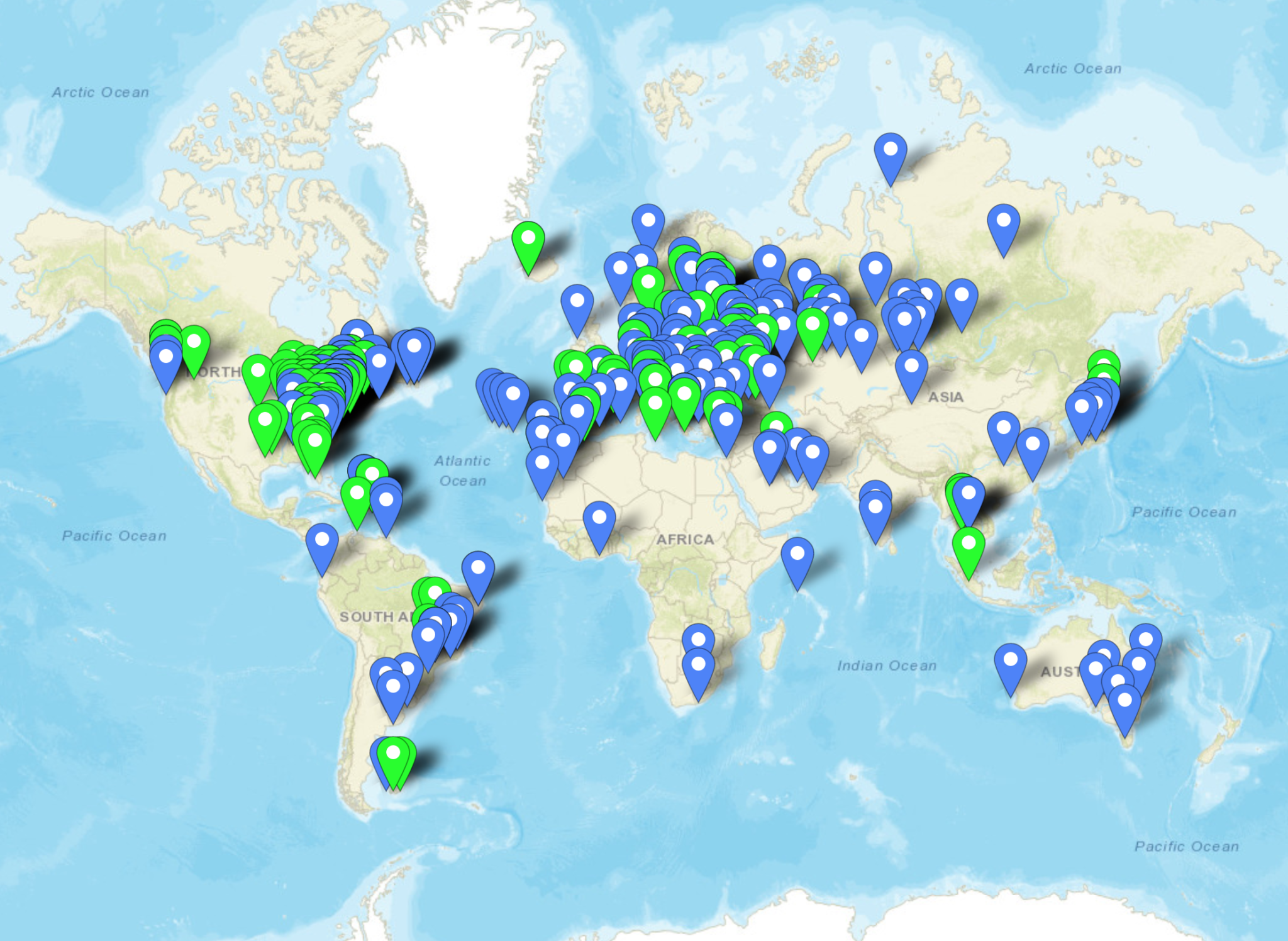
Moving up onto the 30m band I have to admit this is probably my favourite band of all. I’ve spent so many hours on CW working some of the best fists I have ever heard on the air I’ve grown to love this band not just for the DX available but, for the quality of operator found on this narrow piece of the RF spectrum. Needless to say since the antenna is a half wave on the 30m band performance is stunning, out performing any other 30m band antenna I have ever made. It’s even better than the 30m Delta Loop antenna that I built and used when I lived in France.
With 467 contacts in the log on the 30m band you can tell this is my goto band and one that offers access to some of the best DX in the world.
Stations worked on the 30m band from the M0AWS QTH
The 20m band is a band that I never really used until I moved back to the UK from France. Living in France I had acres of land and so I was very much into the low bands, 160m to 30m and never ventured above this part of the spectrum. Now living back in the U.K. with a typical U.K. sized garden the low bands are much more difficult to get onto and so my interests have moved up in frequency somewhat.
Getting onto the 20m band I was amazed at how easy it is to work DX stations compared to the low bands, it’s simply a case of if you can hear them you can work them, there’s no real challenge to be honest. Because of this the band is always super busy with people shouting over the top of each other to get the DX. Not to be put off, I’ve made a surprising 412 contacts on 20m covering the globe. This antenna works incredibly well on this band and you really don’t need anything else to work DX on 20m.
Stations worked on the 20m band from the M0AWS QTH
Next is the 17m band, one of the WARC bands that I’ve never really ventured onto until now. I have to admit I really like this band, when it’s open it’s normally open to the world all at the same time. With an almost undetectable background noise level you can hear the faintest of signal on this band. This is one of the bands that according to the EzNEC modelling software this antenna shouldn’t be any good on but, I have to say that it’s performance is beyond anything I ever imagined. I’ve worked my longest distance yet on this band and with this antenna, ZL4AS at 11776 miles, a distance I haven’t achieved yet on any other band. The 17m band really is a great band, I’d actually say it’s better than the 20m band even though there is considerably less spectrum available. With 220 contacts in the log it’s been a fun band to use.
Stations worked on the 17m band from the M0AWS QTH
Continuing the theme of the WARC bands, the 15m band is another one that I’ve only discovered in the last 12 months. It’s only now that I realise what I’ve missed out on due to my addiction to the low bands for so many years.
I’ve only made 76 contacts on the 15m band, not a lot at all really. This is mainly due to the fact that I get easily side tracked by the 17m and 30m bands most of the time and the radio VFO never gets as far as 21Mhz. Performance of the antenna is good on 15m, I would say not as good as on the 17m band but, it’s no slouch by any means.
As you can see on the map below, I may of only made 76 contacts on the 15m band but, they are spread right across the world proving that this antenna’s DX-ability on 21Mhz really is rather good.
Stations worked on the 15m band from the M0AWS QTH
Finally we arrive at the top of the WARC bands, the little 12m band. Once again this band is very much like the 17m band, super low background noise level, when it’s open you can work huge distances with very little power but, often there is quite deep QSB that can make getting that elusive DX a bit more challenging.
With only 66 contacts in the log once again I’ve not spent a huge amount of time on this band but, it hasn’t disappointed. With global coverage from this antenna on 12m once again I am astounded at how well it works. With software modelling saying it should be terrible on 24.9Mhz with nothing but super high angle radiation, it really shouldn’t be a good antenna for DXing on this upper WARC band but, it is and I have no idea as to why!
Stations worked on the 12m band from the M0AWS QTH
Finally we arrive at the 10m band, another band that I have never got into even though many refer to it as the magic band. This is the band that I’ve made the fewest contacts on, not because the antenna doesn’t work at the dizzy heights of 28Mhz but, because I hardly ever get the VFO dial past the lower bands due to the level of DX available. I really should make more effort to get the best out of the 10m band, especially now the summer is coming.
With a measly 19 contacts in the log I should be ashamed of myself for not doing more on this band as it is very often open and busy with traffic. Since I’ve not really used the antenna that much on the 10m band it’s hard to say how well it performs however, I have had contacts into North and South America and so it shows potential.
Stations worked on the 10m band from the M0AWS QTH
As you can see, the performance of this antenna is self evident from the log entries, it works superbly even though the modelling software says it shouldn’t above 14Mhz. This is now my main antenna here in the U.K. and I’ve only made one change to the initial setup and that is to add a CG3000 remote auto ATU to replace the home-brew LC tuning circuit.
CG3000 Remote Auto ATU housed in a plastic box
With the CG3000 auto ATU in place I no longer have to venture out into the cold, wet garden in the winter months to change band, it’s just a case of sending a continuous 10w signal into it and leaving it to tune in less than 2 seconds. The CG3000 is a Pi Network ATU so it handles both high and low impedance loads with ease. A Pi Network ATU is one of the best you can have, I’ve made my own in the past and had excellent results.
So in summary, 13.4m of wire vertically up a 12.4m pole with 4 x 12m radials, a ground rod and a CG3000 Auto ATU will give any HAM station the ability to work DX on all bands from 80m to 10m without ever having to leave the shack to tune it.
Since I got the CG3000 off of Ebay for a bargain £170 and the 12m heavy duty Spiderpole for under £100 the total cost of the antenna is considerably less than many commercial offerings available and yet performs as well if not better.
If you want to get this antenna onto the 160m band then you just need to add a small coil into the mix at the bottom of the wire to increase the inductance in circuit. The CG3000 will then happily tune the entire 160m band. It’s best to remove this coil though for all the other bands otherwise performance is reduced.
Please be aware that the performance of this antenna will not be anywhere near as good if you use the ATU in your radio at the end of a coax run. This is because the coax becomes part of the antenna and the radiation pattern is all but destroyed. You will be extremely disappointed if you use the antenna in this fashion. The ATU must be at the end of the wire and connected directly to ground and the radials to get the performance that I have experienced.
Finally, if you have an Icom IC-705 and AH-705 remote auto ATU you can use the AH-705 ATU in place of the CG3000, you will get the same results as I have with the CG3000.
I have used my AH-705/IC-705 combo quite a few times with this antenna with excellent results although, the big antenna can sometimes result in the receiver of the IC-705 getting overloaded especially on the lower bands. This is easily resolved by reducing the RF Gain on the radio.
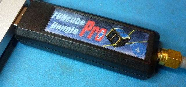
Many years ago I purchased a Funcube Dongle Pro+ (FCD) SDR. Since it’s arrival it has just been stored in my “Get round too it” drawer.
It’s been many years but, today is the day it comes out into the light and finally gets powered up.
Funcube Dongle Pro+ USB SDR
I’m hoping to be able to use the FCD as the receiver in my QO-100 satellite ground station setup.
The output from the 10Ghz dish mounted LNB is around 739Mhz, well within the FCD receiver range of 150khz to 2Ghz. This will save me from having to transvert from 739Mhz to 430Mhz (70cm band) on the receive path.
This will also give me full duplex operation as I will use my Icom IC-705 on the 2m band (144-146Mhz) to drive the 2.4Ghz transverter for the satellite uplink whilst listening to my own signal via the 10Ghz downlink fed into the FCD.
Before I can even start to build the QO-100 satellite ground station I need to get to grips with the FCD, get the software installed, configured, resolve audio routing via virtual audio cables and get it decoding FT8/JS8/WSPR etc.
Checking the Ubuntu repo’s I found that GQRX v2.12 is available for installation.
sudo apt install gqrx-sdr
Once installed I fired up GQRX and set about configuring it. Initially it appeared to have automatically detected and configured the FCD however, when I started the FCD the software ran for 5 seconds and then just hung.
Diving into the configuration settings I found that the FCD actually appears twice in the list of available devices and all I had to do was select the other one in the list and start the software again and all was well.
I connected my 20m Band EFHW Vertical antenna and trawled up and down the band. The receiver performed well even with fairly strong signals so, I spent some time listening to a few of the stations coming in from the USA.
Next I wanted to sort out the configuration for digital modes. I already have a couple of virtual audio cables in the form of loopback audio devices configured on my Kubuntu PC as this is how I connect the audio between WFView for the IC-705 and WSJT-X/JS8CALL.
Sadly, GQRX doesn’t recognise the loopback audio devices that already exist and so I had to do a little further research to get to the bottom of the issue.
Digging deeper I discovered that GQRX requires loopback audio devices created using Pulse Audio and not the kind I had already created at the O/S level. A quick read of the pactl man page and some further searching online I found all the info I needed to create the correct kind of loopback audio devices.
Two commands are required to create the pulse audio server audio loopback devices:
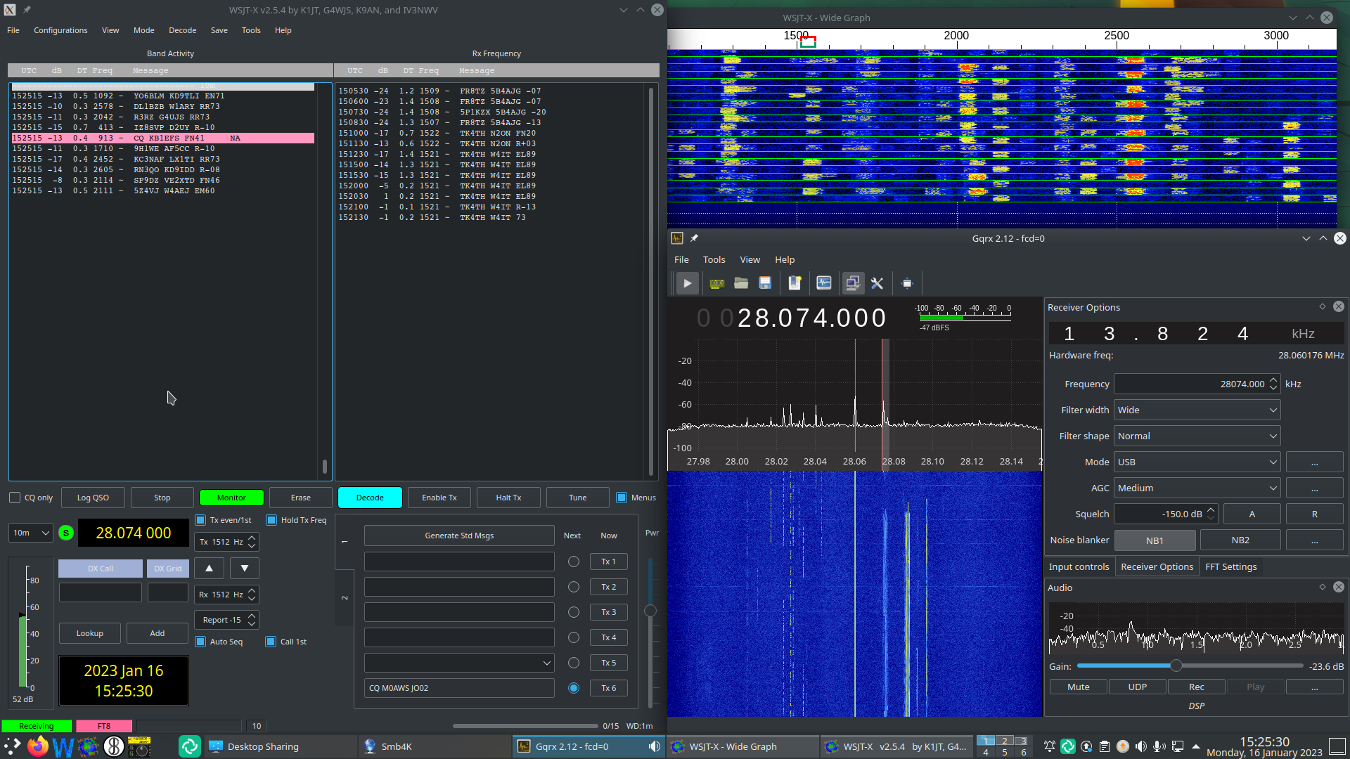
Once I’d created the loopback audio devices I was able to select the gq2jt devices in both GQRX and WSJT-X/JS8CALL so that the audio was routed correctly.
GQRX SDR and WSJT-X working with the Funcube Dongle Pro+
The overall solution works well and doesn’t put much load on the CPU of my Kubuntu PC, leaving plenty of horse power for me to do other things at the same time.
So I now have the Funcube Dongle Pro+ working perfectly on my Kubuntu PC, all I need now is a 1.2m dish, a 10Ghz LNB and some high quality coax cable.
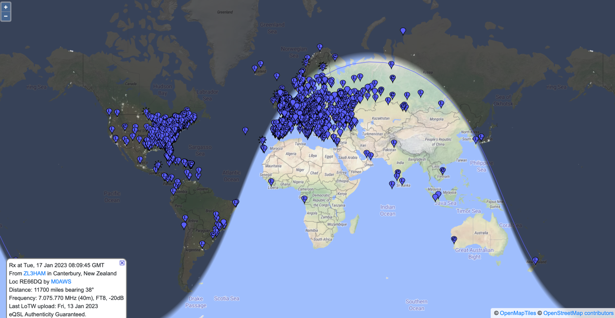
UPDATE: I decided to leave the FCD connected to the 20m Band EFHW Vertical overnight and monitor FT8 on the 40m band. The EFHW antenna isn’t anywhere near resonant on the 40m band and so I thought it would be interesting to see how well the FCD performed on a completely non-resonant antenna.
To my surprise it did exceptionally well, stations from all over the world were heard with ease, the FCD really is an excellent little SDR receiver.
Map showing stations heard on 40m Band FT8 over night 16/17 Jan 2023
If you’re looking for a relatively cheap but, effective receiver for FT8/WSPR monitoring then I can highly recommend the FCD. If paired with a RaspberryPi then it would be a really cheap to purchase/operate solution for any HAM operator or short wave listener (SWL).
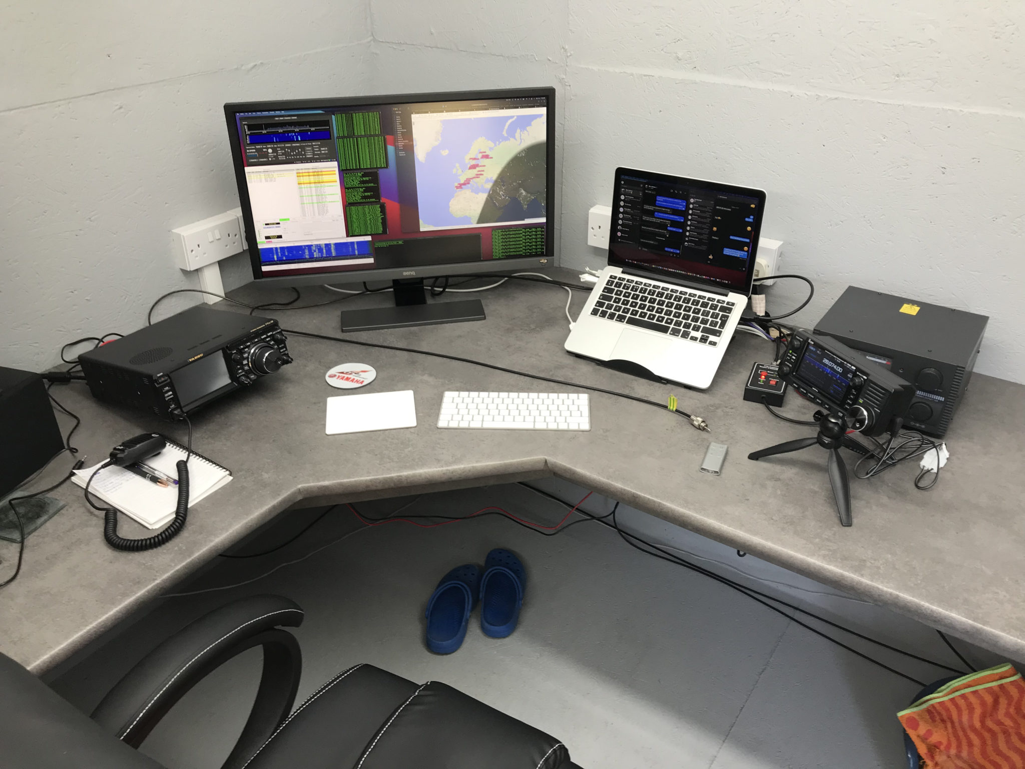
I’ve been chasing the DX on the HF bands using FT8 for a while now and I have to say it’s been very successful however, it does get rather boring after a while just exchanging SNR reports and nothing else. I noticed that my time spent in the shack was getting less and less, not a good sign after all the work I’d put into building the new radio shack.
Since there’s not a lot of CW on the bands these days (everyone is on FT8) I thought I’d give JS8CALL a go.
Initially I started with trying to get JS8CALL working on my Kubuntu PC to my Icom IC-705 wirelessly. This turned out not to be as straight forward as I’d hoped but, I persevered.
I found that to communicate with the IC-705 via WFview wirelessly I needed to use FLRig as a go between. I installed FLRig from the Ubuntu repo’s only to find it’s an old version that doesn’t have support for the IC-705. Downloading the IC-705.xml file didn’t help either so I uninstalled it and headed to the source forge website to grab the source code for the latest version of FLRig.
Once I had the right development libraries installed compiling the code was easy enough and I soon had FLRig talking to the IC-705 via WFview wirelessly from my Kubuntu PC.
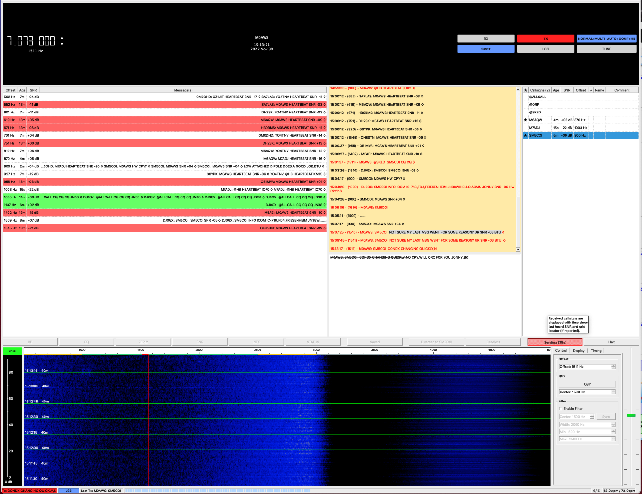
My first JS8 QSO was with Jonny, SM5COI in Sweden on the 20m band, using just 2.5w I had a very reliable link from my 20m band EFHW vertical antenna to his 20m band yagi antenna.
I also worked GM0DHD/P via OH8XAT using the relay capability built into JS8CALL, it works incredibly well and allows you to work the stations that you cannot hear directly, very useful!
Later in the morning Jonny, SM5COI emailed me asking for a sked on the 40m band later in the afternoon, of course I agreed and decided that I’d also get my MacBook Pro setup with JS8CALL so I could give my Yaesu FTDX10 a spin on JS8 mode.
Installing and configuring JS8CALL on my MacBook Pro was much easier and I had it fully operational in minutes.
The sked went well on 40m and it was good to get Jonny on another band.
With 3 JS8 QSOs in the log it’s great to be using a digital mode again that allows you to have a good chat with other radio HAMs around the world. I think this may become my preferred digital mode going forward.
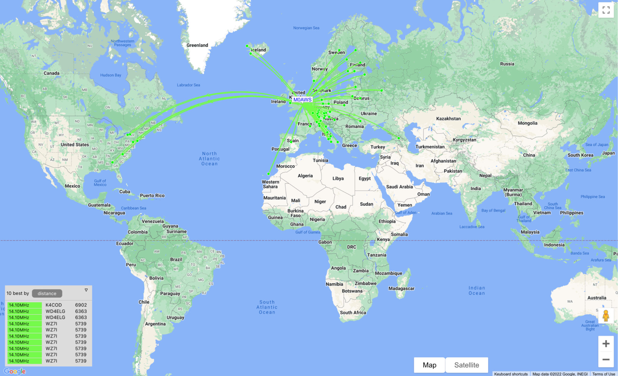
For the last 24hrs I’ve had the RaspberryPi2 transmitting WSPR on 20m and 10m connected to my EFHW Vertical antenna. So far not a single spot on the 10m band, I’m assuming the band hasn’t opened in the UK over the test period.
WSPR 20m band reports over the last 24hrs
Results on 20m continue to impress with reports from the USA, West Africa coast and as far east as Georgia.
I’ll check the signal on 10m later today using my IC705 to ensure it is transmitting ok and then will leave it running for another 24hrs to see what happens.
UPDATE:
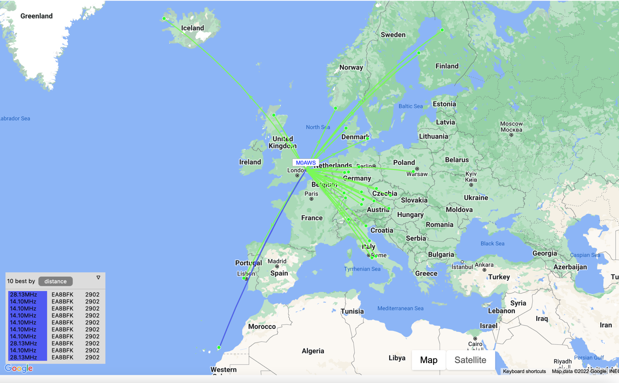
It appears there’s been a reliable opening on both 10m and 20m to the Canary Islands just off the west coast of Africa so far today.
The Weak Signal Propagation Reporting Network (WSPR) known as “Whisper” in the HAM community is a QRP/QRPp beacon mode that is used by many HAMs around the world to see pretty much realtime propagation on the HF bands.
I first started using WSPR when I lived in France some years ago and it proved invaluable for assessing antenna performance and directivity. It’s not a new mode by any means and nowhere near as popular as it used to be as it’s really been superseded by FT4/8 these days that provides the same functionality but, with QSO capability too.
Having an old RaspberryPi hanging around and reading about the WSPR software that’s available for it now I decided to put the Raspi to good use and build a WSPR beacon for the 20m band that I could leave on 24/7.
Having the EFHW Vertical at the end of the garden means that I can connect it directly to the Raspi without the need for an ATU as it’s fully resonant. (It’s actually resonant on 20m and 10m)
I normally run both my RaspberryPi mini computers completely headless and then SSH in to them from my MacBook Pro and decided this was the best way to go with the WSPR beacon too since the WSPR software is command line based and doesn’t require a GUI.
First thing to do was to upgrade the OS from Debian Buster to Bullseye. It’s been a while since I used the Raspi but, it fired up perfectly and connected to the LAN without issue.
After a little time I had the O/S updated to Bullseye and the Raspi was ready for the software build.
The WSPR program comes in source code only so, this means you have to compile it yourself. This isn’t a big job as it comes complete with a makefile.
Using a terminal run the following commands to download and compile the WSPR source code.
So first thing to do is install git.
sudo apt-get install git
Once git is installed I downloaded the software from the git repository.
It only takes a few seconds to download the software which is stored in a new directory called “WsprryPi”.
Before the code can be compiled there’s a small issue with the includes in one of the source code files that needs to be resolved so that the code compiles without error.
cd WsprryPi
vi mailbox.c
Using your favourite command line editor, ‘vi‘ in my case I added the following line into the include statement at the top of the code.
#include <sys/sysmacros.h>
Once added the full include statement looked like this:
Once done, I saved the file ready for compilation.
Compiling the code is easy, just run the make command and sit back and watch all the compiler messages scroll across the screen.
make
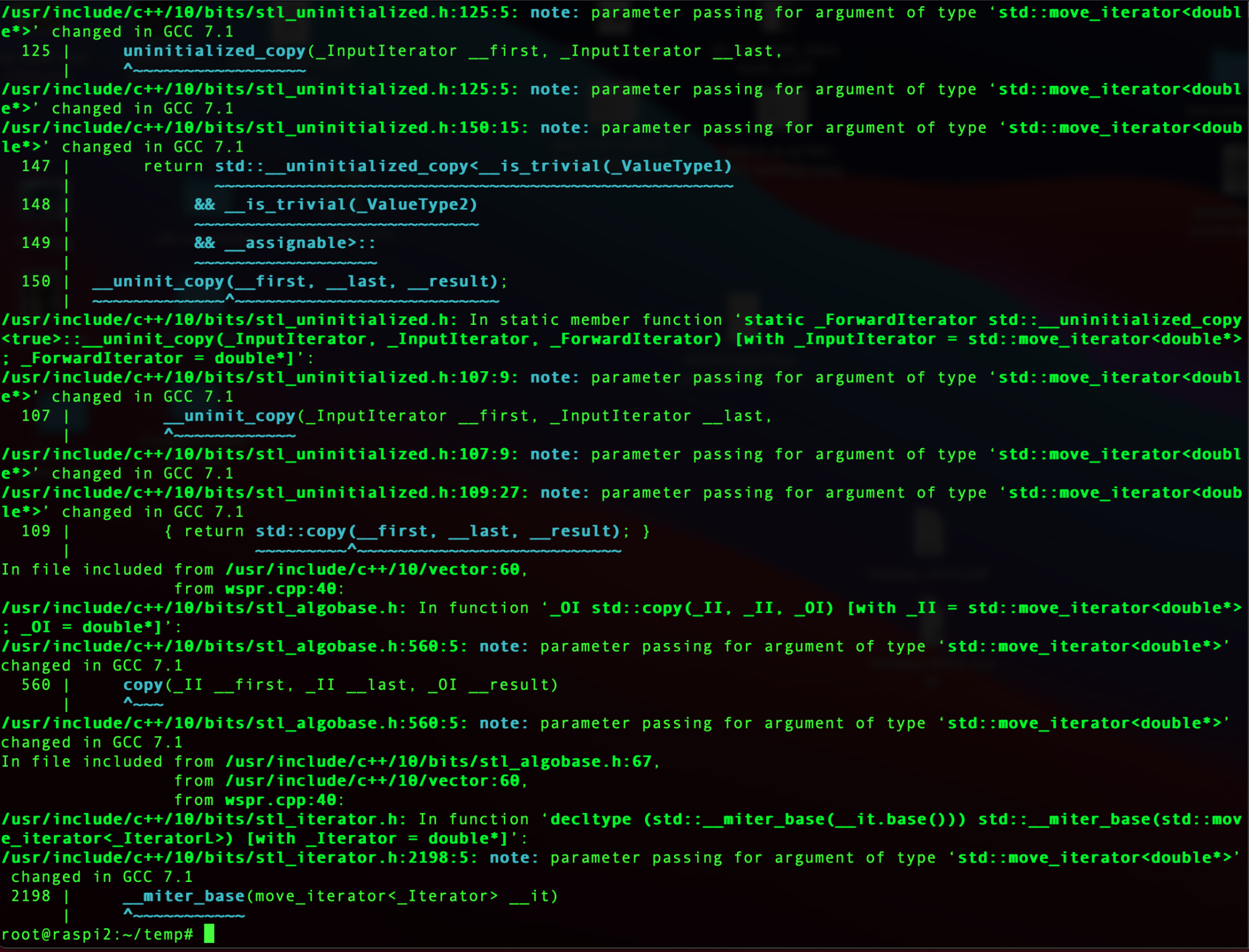
Compiling the WSPR source code
Once compiled without errors, I just needed to install the binary.
make install
At this point the software is ready to go.
I quickly soldered up a lead to go from the RaspberryPi GPIO pins to the Coax cable that is connected to the EFHW vertical antenna in the garden and connected it all up ready to test.
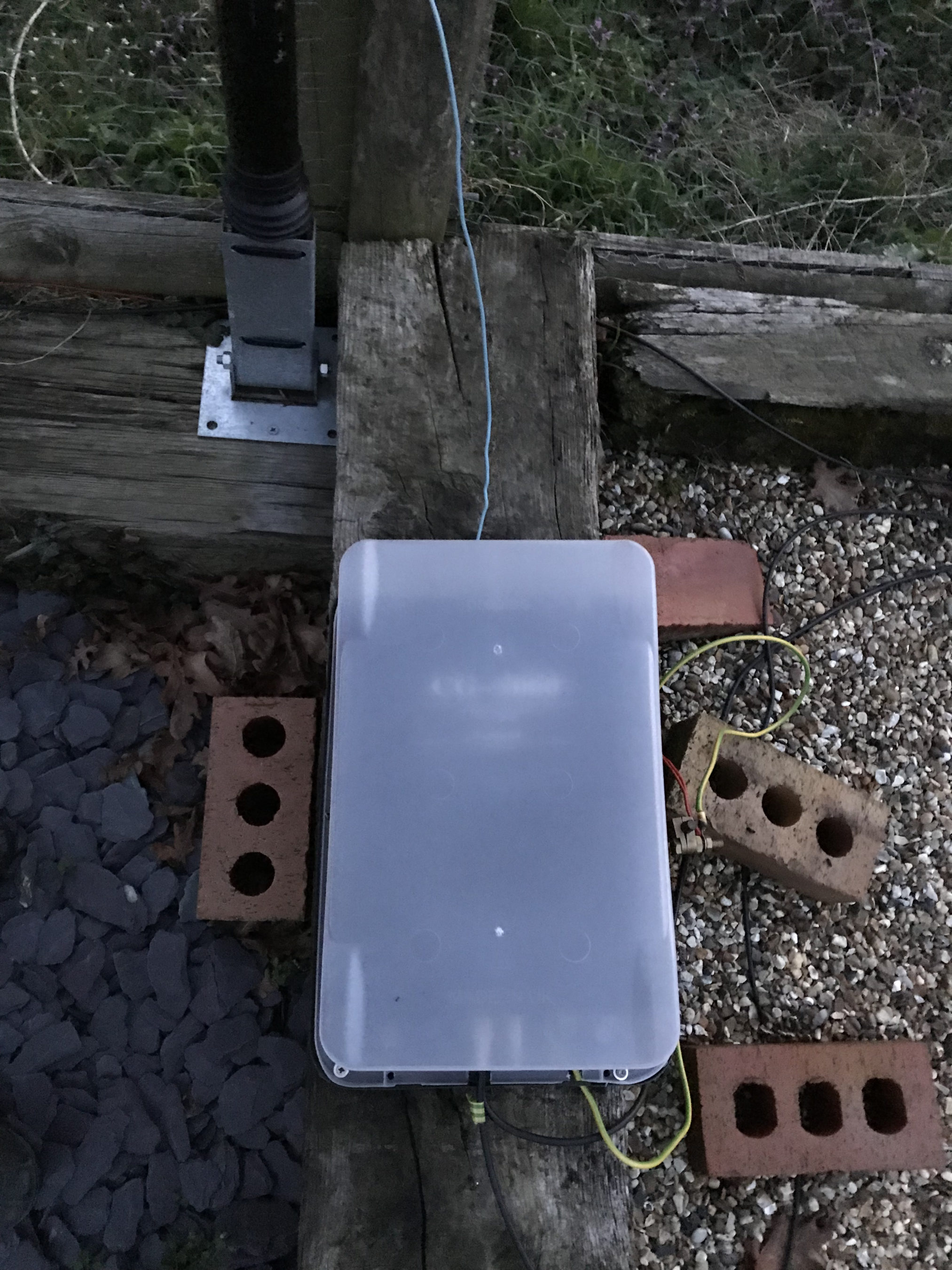
RaspberryPi 2 WSPR Beacon connected to EFHW vertical for 20m/10m bands
Pins 7 and 9 on the Raspberry Pi’s GPIO pins are where the signal is output. Pin 9 is the Ground pin, and pin 7 is the Signal pin. Pin 7 goes to the inner of the coax and pin 9 to the ground side of the coax.
The purple cable is the ethernet cable connecting the Raspi to my local LAN so that I can access it remotely via SSH. I’ve powered the Raspi off of the USB port on the wifi access point in the radio shack which is always on.
Once it’s all connected it’s just a case of starting the WSPR program from the command line as user root.
wspr -s -r M0AWS JO02 10 20m > ./wspr.log &
I run the WSPR program as root user so that it has the correct privileges to access the devices to communicate with the GPIO headers, if you want too start it as your normal user then you’d need to use sudo to gain the root privileges.
The command line options I’ve used are as follows:
-s
Check NTP before every transmission to obtain the PPM error of the crystal
-r
Repeatedly, and in order, transmit on all the specified command line freqs.
M0AWS
My Callsign
JO02
My Locator Square
10
The power being used in dBm
> ./wspr.log &
Redirects all output to wspr.log in the current directory and then puts the program into the background so that it is left running when I log out.
Once the program is started you can monitor progress by using tail on the log file.
tail -f ./wspr.log
The output you will see will be something like this.
Desired center frequency for WSPR transmission: 14.097100 MHz
  Waiting for next WSPR transmission window...
  TX started at: UTC 2022-07-17 16:06:01.015
  TX ended at:   UTC 2022-07-17 16:07:51.638 (110.623 s)
Desired center frequency for WSPR transmission: 14.097100 MHz
  Waiting for next WSPR transmission window...
  TX started at: UTC 2022-07-17 16:08:01.015
  TX ended at:   UTC 2022-07-17 16:09:51.639 (110.624 s)
Desired center frequency for WSPR transmission: 14.097100 MHz
  Waiting for next WSPR transmission window...
  TX started at: UTC 2022-07-17 16:10:01.015
  TX ended at:   UTC 2022-07-17 16:11:51.642 (110.627 s)
Desired center frequency for WSPR transmission: 14.097100 MHz
  Waiting for next WSPR transmission window...
  TX started at: UTC 2022-07-17 16:12:01.015
  TX ended at:   UTC 2022-07-17 16:13:51.639 (110.624 s)
Desired center frequency for WSPR transmission: 14.097100 MHz
  Waiting for next WSPR transmission window...
  TX started at: UTC 2022-07-17 16:14:01.015
  TX ended at:   UTC 2022-07-17 16:15:51.639 (110.624 s)
Desired center frequency for WSPR transmission: 14.097100 MHz
  Waiting for next WSPR transmission window...
  TX started at: UTC 2022-07-17 16:16:01.014
  TX ended at:   UTC 2022-07-17 16:17:51.639 (110.624 s)
Desired center frequency for WSPR transmission: 14.097100 MHz
  Waiting for next WSPR transmission window...
  Obtained new ppm value: 4.09996
  TX started at: UTC 2022-07-17 16:18:01.015
  TX ended at:   UTC 2022-07-17 16:19:51.640 (110.624 s)
Desired center frequency for WSPR transmission: 14.097100 MHz
  Waiting for next WSPR transmission window...
  TX started at: UTC 2022-07-17 16:20:01.014
  TX ended at:   UTC 2022-07-17 16:21:51.638 (110.624 s)
Desired center frequency for WSPR transmission: 14.097100 MHz
  Waiting for next WSPR transmission window...
  TX started at: UTC 2022-07-17 16:22:01.004
  TX ended at:   UTC 2022-07-17 16:23:51.628 (110.624 s)
You can pass multiple bands on the command line if you want to hop around bands.
It’s also recommended that you add a low pass filter between the Raspi and coax connection to help suppress any harmonics that may be generated. You can make one easily enough using just a capacitor or there are a number of prebuilt low pass filters specifically made for the GPIO hat on the Raspi online.
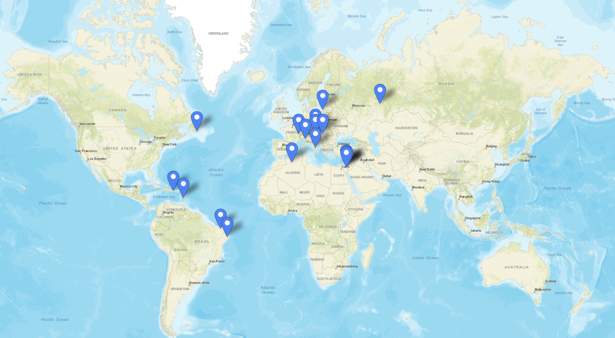
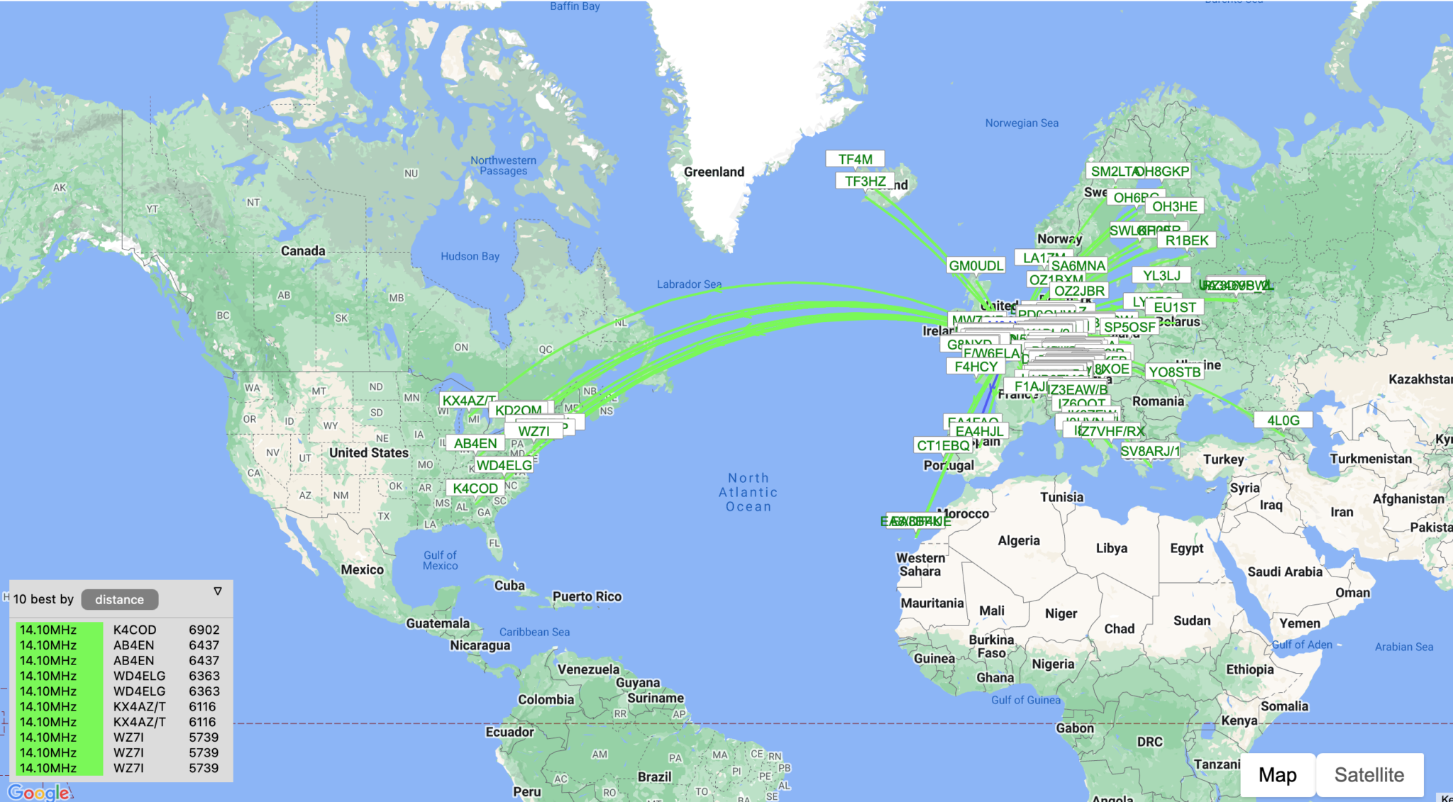
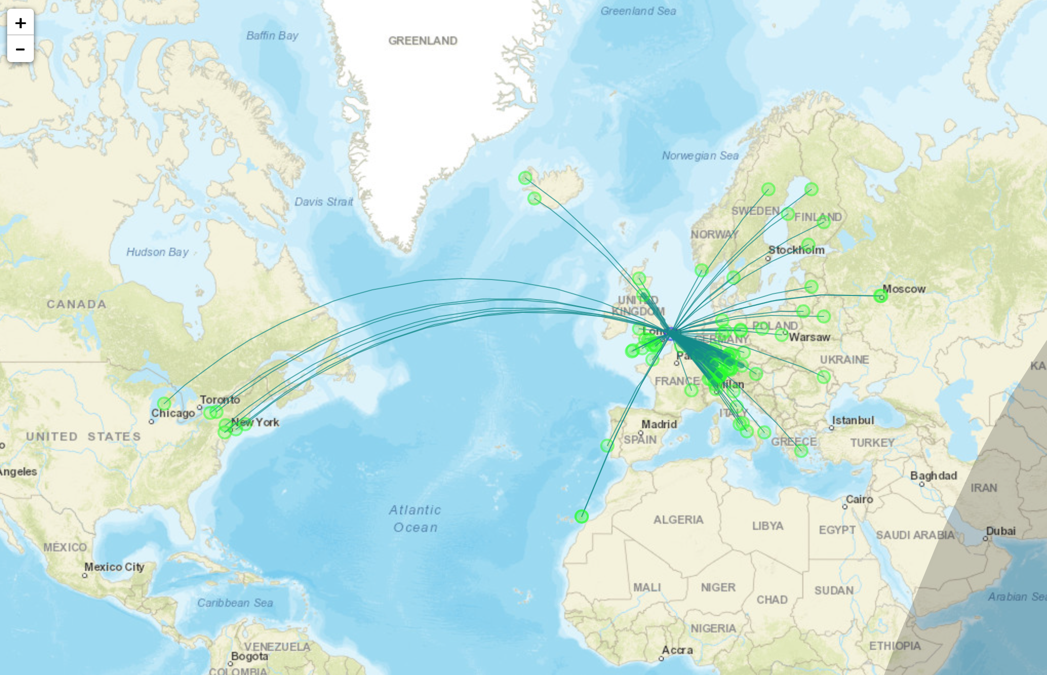
With only 10dBm (10mW) output from the RaspberryPi it’s surprising the distances that the signal travels. In no time at all I had reports from all over Europe and as the day progressed reports started coming in from Iceland, the USA and Russia.
Map showing stations that heard M0AWS on WSPR
I used http://wspr.aprsinfo.com WSPR monitoring website to watch progress as the day went on and after 24hrs had been heard by a number of stations over 3000 miles away.
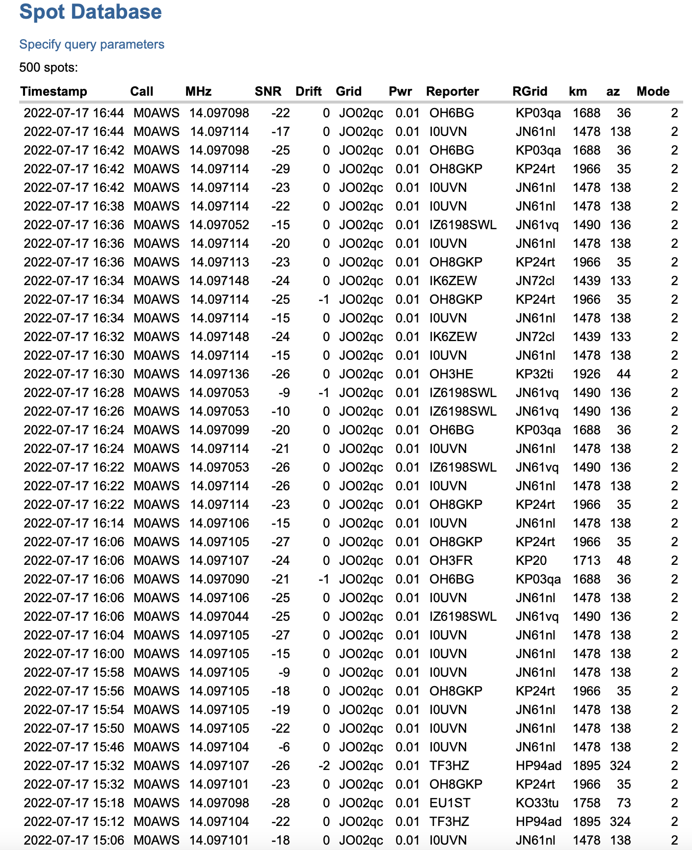
You can also get a more detailed view of reports from the WSPRnet website where you can query the database and create a detailed list of all decodes over a set period of time.
Detailed list of WSPR decodes
Since my EFHW Vertical is resonant on both 20m and 10m I’ll now run it for the next 24hrs on both bands to see what results I get.
Now that I’ve got my new radio shack up and running I decided to give my Icom IC-705 QRP rig an outing and see if I could work a distance of 2000 miles with 1w output.
This is something I’ve been wanting to do for a while but, only being able to sit at the picnic table in the garden or in the summer wasn’t particularly conducive to a long stint on the radio.
Icom IC-705 wirelessly connected to my MacBook Pro
For this challenge I decided to use FT4 or FT8, whichever was active on the bands. This is a great mode for QRP operations and can get a tiny signal through when other more traditional modes fail.
I used both my EFHW vertical for 20m/10m and my EFHW vertical for 30m that can also be tuned on most of the other HF bands too. This gave me most of the HF bands for the challenge.
Initially I worked a lot of stations in the 600-700 mile range, conditions weren’t brilliant and there was a lot of deep QSB.
My first notable distance QSO was with YO4DG near Mangalia Romania at 1383 miles, this equates to 0.72mW/Mile, my lowest mW/Mile achievement up until this point.
Not long afterwards I saw SV8DCY on the WSJTX waterfall, I wasn’t sure if he’d hear me or not but, I gave a call. To my surprise he came back and became the longest distance QSO for a short time. At 1485 Miles to Kalloni Lesvos Island, Greece this equates to a new low of 0.67mW/Mile.
I then went on to work a bunch of stations in the 1000 miles or less range for a while as conditions on the bands were up and down. It’s amazing how many times I got an answer from a station only for them to disappear completely before the QSO was completed.
The next contact of note was with CU3HN in the Azores, 1713 Miles at 0.58mW/Mile, a new lowest mW/Mile record set. it’s amazing how far you can get a signal with such a tiny amount of power.
RV6F in the Stavropol region of Russia was the next big mile marker, 1932 miles at 0.51mW/Mile. It took a number of attempts to get the QSO to complete as we kept losing each other due to the deep QSB that was between us on the 20m band but, with a little patience and persaverance we eventually got the QSO to complete and it was in the log.
At this point I decided to switch over to the 10m band to see if it had opened up to more than just Europe. When I checked earlier there were only European stations being heard, most being well under 1000 miles. Sure enough the band had indeed opened up and I was hearing stations out to the east that were in excess of 2000 miles.
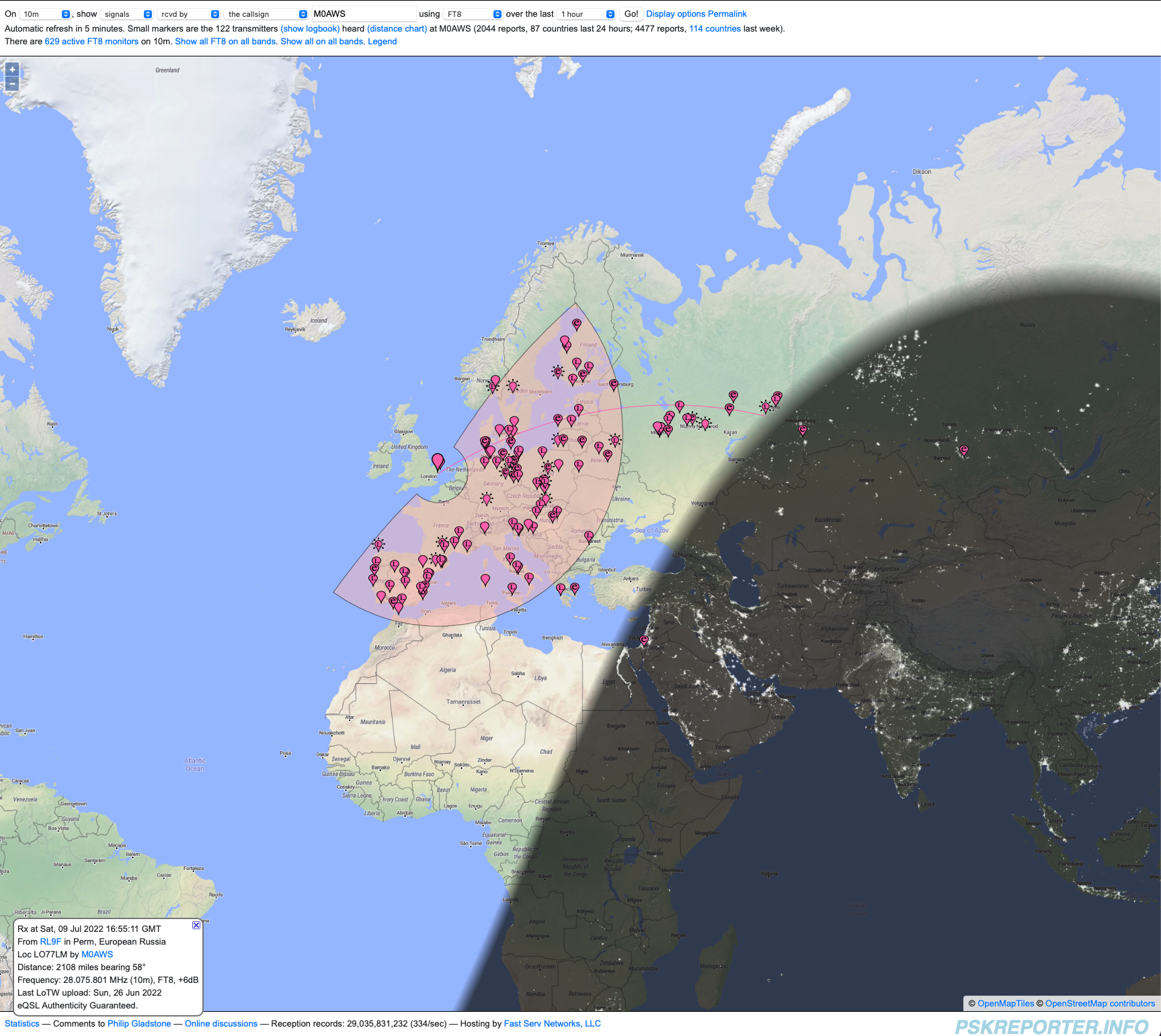
PSKReporter map showing signals heard on the 10m band
After tuning up and listening for a bit my first call was to RL9F in Perm Russia. This was the one that I’d been looking for, 2084 miles at 0.47mW/Mile this was the one that could complete the challenge.
After a few failed attempts due to deep QSB we eventually got a complete QSO in the log finishing the challenge.
2000 miles using 1w is a lot of fun, frustrating at times when you’re being heard by stations on the east coast USA but, none are answering your reply to their CQ calls.
PSKReporter has proven invaluable, being able to see who can hear you makes a big difference when trying to eek out the last mile when using next to no power.
In total 31 stations were worked over a 9 hour period, not huge numbers but, for many an M0AWS call sign isn’t exotic enough to answer and so many of my calls to stations were ignored. Sad really.
You can view all the log entries for the 2000 Mile 1 Watt challenge on my WSJTX Log.
So, what next? Well I guess it has to be 3000 miles or more using just 1w from my trusty Icom IC-705.
To celebrate Her Majesty the Queen Platinum Jubilee, marking 70 years of service to the people of the United Kingdom, the Realms and the Commonwealth, U.K. Radio Amateur (HAM) operators can apply for a Notice of Variation (NOV) to use the Q Regional Secondary Locator.
The RSGB will also be operating a bunch of GB70 special event stations, full details on the GB70 website.
I have my NOV and will be on air using MQ0AWS for the whole of June 2022.
This callsign will operate for one month only and so will be a rare one for you to get in your log.
I will be operating on all HF bands 160-10m CW & FT4/8 and maybe some SSB depending on conditions.
All MQ0AWS logs will be uploaded to my website almost realtime and will be uploaded to EQSL at the end of June 2022.
Operating a QRP station can often make you feel like you’re not getting out when no one responds to your multiple CQ calls. This was the case the other day when I was trying out my new to me Begali Traveler Light morse key.
I was on the 20m band calling and calling to no avail, the band was open as I could hear other stations just fine so I knew there was traffic on the band. The SWR on my EFHW Vertical was perfect as it always is and so I knew there wasn’t a problem with the coax/antenna combination.
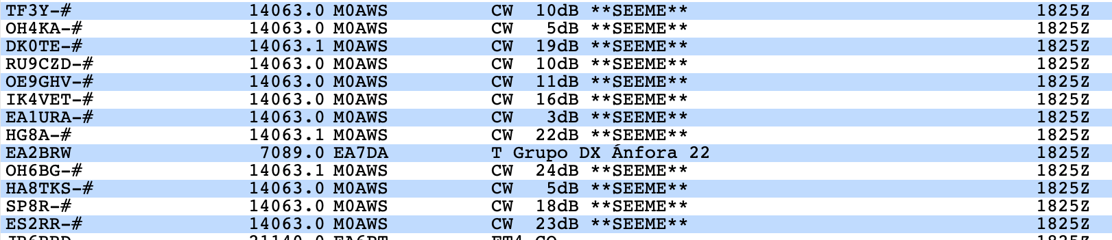
Wanting to know if my signal was indeed going anywhere I decided to make use of the SeeMe facility on the DXCluster that I use. The SeeMe facility effectively allows you to enable spots for your own callsign from the Reverse Beacon Network (RBN).
The SeeMe facility is easily switched on by issuing the set/seeme command on the DXCluster of your choice. Once enabled you will start to see spots for your own callsign from the RBN every time you call CQ using CW.
RBN Spots for M0AWS calling CQ on the 20m Band
As you can see above, I was clearly getting out very well with some great signal reports from a good spread of stations even though I was only using 5w of CW.
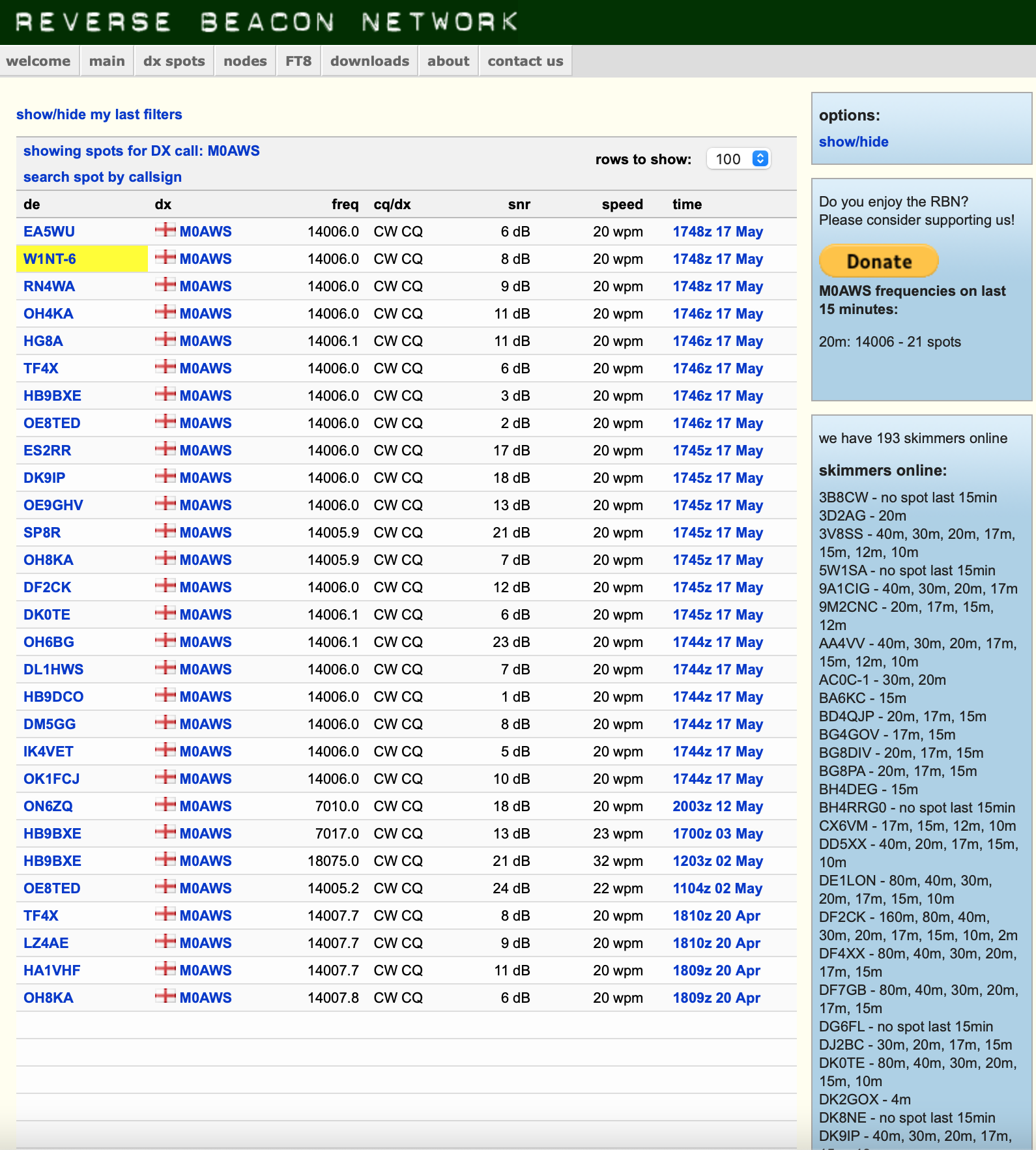
You can of course use the RBN website to view the spots if you prefer, it’s not quite as realtime as the DXCluster but, it provides the same information eventually.
M0AWS spots on the RBN Website
The view on the RBN Website is almost the same as that from the DXCluster however, it also shows your CW speed in WPM. I was also surprised to get a spot from the USA at 8dB, that’s a good signal (Just over S2) considering I was only using 5w of power.
I came to the conclusion that no one needed an exotic M0 call for their log and so I went on to my normal search and pounce approach and worked a bunch of stations spread around Europe and Asiatic Russia. My little 5w signal did well and I was able to get through the pileups by using my slide off to the side technique so that my little signal stood out on it’s own. This technique works well when trying to get a QRP signal into a pileup and is used often.
Needless to say, my Begali Traveler Light twin paddle morse key once setup how I like it was superb to use, light to the touch, quick and responsive. Begali make such beautiful morse keys!
More soon …
We use cookies to ensure that we give you the best experience on our website. If you continue to use this site we will assume that you are happy with it.